1
User's Guide
Black-and-White Raster Plotter
LP-1020
LP-1020L
Read this User's Guide to use the plotter safely and
properly. Keep this manual in a place where you
can quickly access it at any time.
Seiko I Infotech Inc.
Downloaded From ManualsPrinter.com Manuals
Downloaded From ManualsPrinter.com Manuals
U00107742300
U00107742301
November 2007
December 2007
©Seiko I Infotech 2007
Reprinting of this manual without permission is prohibited.
The content of this manual may be changed without notice.
D-SCAN is a registered trademark of Seiko Instruments, Inc.
Ethernet is a registered trademark of Xerox, Inc.
HP is a registered trademark of Hewlett-Packard (U.S.A.)
MICRO CADAM is a trademark of CADAM, Inc. (U.S.A.)
Athlon is a trademark of Advanced Micro Device, Inc.
Intel, Pentium and Core are registered trademarks or a trademark of Intel Corporation.
This equipment has been tested and found to comply with the limits for a Class A digital device,
pursuant to Part 15 of the FCC Rules. These limits are designed to provide reasonable protection
against harmful interference when the equipment is operated in a commercial environment.
This equipment generates, uses, and can radiate radio frequency energy and, if not installed and
used in accordance with the instruction manual, may cause harmful interference to radio
communications. Operation of this equipment in a residential area is likely to cause harmful
interference in which case the user will be required to correct the interference at his own expense.
Durch die Kennzeichnung dieses Produktes mit dem CE-Zeichen erklärt Seiko den folgenden
Direktiven der Europäischen Union zu entsprechen (mit Wirkung vom siehe Datum):
Januar 1996:- EG-Direktive 73/23/EEC ergänzt durch EG-Direktive 93/68/EEC, Angleichung der
Gesetze der einzelnen Mitgliedsstaaten bezüglich Geräten mit niedriger Betriebsspannung.
Januar 1996:- EG-Direktive 89/336/EEC, Angleichung der Gesetze der einzelnen Mitgliedsstaaten
bezüglich elektromagnetischer Kompatibilität.
Den vollständigen Text dieser Erklärung einschließlich der Definition der entsprechenden
Direktiven sowie der jeweiligen Standards erhalten Sie von Ihrem Seiko Colorgrafx Systems
Kundendienst oder Ihrem Seiko Engineering Systems Kundendienst.
This Perchlorate warnig applies ONLY in California USA
“Perchlorate Material - special handling may apply,
See www.dtsc.ca.gov/hazardouswaste/perchlorate”
Downloaded From ManualsPrinter.com Manuals
CE Marking
It is legally mandatory for products distributed or sold in the EU to bear a CE Mark that
indicates compliance with requirements set forth in EC directives for the particular
product. These directives set the scope of machinery subjected to the specific directive.
Our LP-1020 complies with the EMC Directive (2004/108/EC) and Low Voltage Directive
(2006/95/EC).
For inquiries concerning CE Marks:
Seiko Instruments Europe S.A
European Head Office
Avenue de Messidor 198, 1180, Brussels, Belgium
TEL: +32 (0) 2 346 62 74
FAX: +32 (0) 2 347 52 68
Downloaded From ManualsPrinter.com Manuals
Introduction
Thank you for purchasing our LP-1020/1020L Black-and-White Raster
Plotter (hereafter referred to as “this device”).
This manual explains the overall device operations, functions and
operation method under the premise that installation of the device has
been completed.
Before using this device, please read the “Safety Precautions” so that you
may operate this device safely and correctly. Keep this manual in a place
where you can quickly access it at any time.
This device employs either one of the following feeders: 1-roll paper
feeder for standard sheet drawings with output up to 2.5 m, or 2-rolls
paper feeder for long sheet drawings with output up to 10 m.
This manual explains how to use the 2-rolls paper feeder devices, but also
accomodates the 1-roll paper feeder devices.
i
Downloaded From ManualsPrinter.com Manuals
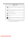
Safety Precautions
The following symbols are used in this manual to ensure the proper use of
the plotter and to prevent the plotter from being damaged.
Please follow these guidelines:
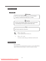
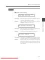
WARNING
Warnings must be followed carefully to avoid serious
bodily injury or death.
CAUTION
Cautions must be observed to avoid damage to your
equipment and bodily injury.
Example of symbols:
This symbol (
) denotes items that require special care while
executing a certain procedure or operation.
This symbol (
) denotes items that are forbidden.
This symbol (
) denotes items you should follow to prevent
accidents or injury.
ii
Downloaded From ManualsPrinter.com Manuals
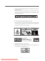
Warning
DO NOT touch any of the parts inside the plotter with a "HIGH
VOLTAGE" label attached as it may result in electric shock.
DO NOT touch any of the parts inside the plotter with a "HIGH
TEMPERATURE" label attached as it may result in severe burns.
DO NOT disassemble or modify the plotter. DO NOT repair the plotter
by yourself. Doing so may cause fire, electric shock or other accidents.
DO NOT throw the toner cartridge or waste toner bottle into fire or
place them near heat as they could explode or catch fire leading to
serious accidents and/or bodily injury.
NEVER use the plotter in a place of extreme humidity or any place
where it can possibly be splashed by any liquids. If any liquids get into
the plotter, it could lead to fire, electric shock, or other serious
accidents.
DO NOT allow metal to touch the internal parts of the plotter. Doing so
may cause fire, electric shock, or other accidents.
DO NOT disconnect or connect the power cable with wet hands. Doing
so may lead to electric shock.
Power OFF the plotter and unplug the power cable from the power
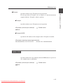
outlet in any of the following cases:
◆ When putting your hands inside the plotter.
◆ Smoke, strange noise or smells erupt from the plotter.
◆ A piece of metal or any liquid touches the internal parts or slots of
the plotter.
◆ An error requiring service from a service center occurs.
Using the plotter in any manner other than for which it was designed may
cause accidents or fire.
iii
Downloaded From ManualsPrinter.com Manuals
Caution
DO NOT disassemble, modify the toner cartridge. If toner gets on your
skin or clothes, wash off the affected area immediately with soap and
water.
Handle the toner cartridge with extreme care. Should any toner get into
your eyes, do not rub them, flush them immediately with water, and see
a physician immediately.
Handle the paper rolls with care because they are very heavy. Dropping
them may lead to personal injury.
Use care when cutting the paper rolls with a scissors or knife during
installation.
DO NOT unplug the electric cable by pulling on the cable. Doing so
may cause the cable to fray or break which could lead to electric shock
and/or fire.
In order to ensure the safe operation of the plotter heed all of the cautions
and warnings contained throughout this manual.
iv
Downloaded From ManualsPrinter.com Manuals
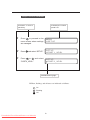
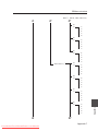
Warning labels
Warning labels are affixed to this device at the locations indicated in the
diagram below. You should understand the meanings of these warning
labels and handling instructions.
3 “WARNING: HIGH VOLTAGE” label
2a “Caution when dealing with
paper jam” label
1 “Caution: high temperature” label
2b “Caution when dealing with
paper jam” label
v
Downloaded From ManualsPrinter.com Manuals
1 “Caution: high temperature” label (It is affixed to the inside of
the fixation door.)
This label cautions you not touch this area due to high temperature.
The fixation device will become hot. Take care to avoid contact when
dealing with paper jams.
2 “Caution when dealing with paper jams” label
This label indicates the direction that jammed paper should be pulled
out when paper is jammed in the fixation device. Follow the
directions on the label to remove the paper.
a
b
3 “WARNING: HIGH VOLTAGE” label
This label cautions against contact due to high voltage application. As
it is dangerous, never contact this area.
vi
Downloaded From ManualsPrinter.com Manuals
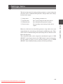
How to read this manual
Manual make-up
This manual is composed of 13 chapters and an appendix.
Chapter 1 provides information that you should know before using this
device, such as device features and part names. First read chapter 1 for an
understanding of basic matters pertaining to this device.
Chapter 2 provides information on matters you will need to know to
operate this device, such as turning the power on and off, and how to put
paper in the device. Refer to this chapter for basic information on
operating this device.
Chapters 3 to 13 provide information on device functions, operation and
how to manage the settings. First read chapters 3 and 4 for an overview
of functions and operations. Then proceed to the chapter you want to
refer to.
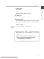
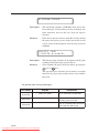
Chapter 5:
Refer to this chapter when setting the data format you
will use.
Chapter 6:
Refer to this chapter when setting the operating
conditions for the engine of this device.
Chapter 7:
Refer to this chapter when you have loaded a different
type of paper in the device and you must change the
settings accordingly.
Chapter 8:
Refer to this chapter to confirm Setup contents or to set
the date and time.
Chapter 9:
Refer to this chapter when setting the communication
protocol.
Chapter 10:
Refer to this chapter when conducting initialization.
Chapter 11, 12: Refer to these chapters when setting the communication
conditions for Ethernet and parallel connection or when
returning to the default settings.
Chapter 13:
Refer to this chapter when using "Teioplot".
Chapter 14 provides information on troubleshooting if a problem occurs
with this device. Appropriate countermeasures should be conducted in
accordance with the explanations in this chapter.
The basic specifications and command list for this device can be found in
the appendix. The menu structure is explained in great detail here. Refer
to this menu to perform settings for menus which are not fully explained
by the setting operations for chapters 5 to 13.
vii
Downloaded From ManualsPrinter.com Manuals
Notation method
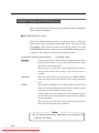
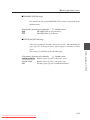
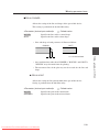
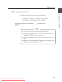
Markings
Warning
◆ This mark indicates warnings that must be followed
carefully to avoid serious bodily injury or death.
Caution
◆ This mark indicates cautions that must be observed to
avoid damage to the equipment and bodily injury.
Note
◆ Contain important information.
This is a “Tip” mark.
Contain additional hints for better use.
⇒
This is a “See” mark.
A reference section and page is indicated after this mark.
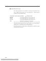
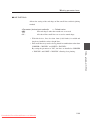
DSCAN format
Please remember:
The DSCAN format described in this manual as well as DSCAN that
appears on the operation display are for only customers in Japan.
viii
Downloaded From ManualsPrinter.com Manuals
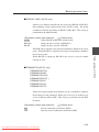
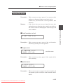
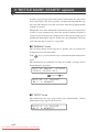
Key/LCD/LED notations
Indicates a control
panel key.
1
2
3
Indicates the control
panel LCD.
Press
to proceed to the
menu screen where settings
are managed.
Press
MENU
# SETUP
SETUP
# POR T 1 _ H PG L
and select “SETUP.”
Press
or
and select
“PORT2_HPGL.”
SETUP
# POR T 2 _ HPG L
Indicates flashing light
LED on, flashing, and off states are indicated as follows:
On
Flashing
Off
ix
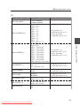
Downloaded From ManualsPrinter.com Manuals
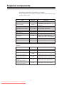
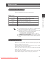
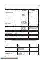
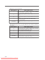
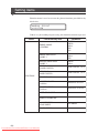
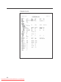
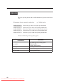
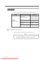
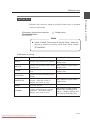
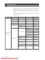
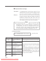
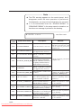
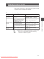
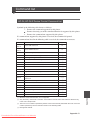
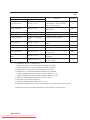
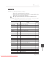
Supplied components
Components and options listed below are included.
If any components are missing or broken, contact your retailer or your
nearest service center.
Item
Quantity
Remarks
Plotter unit
1 unit
Toner cartridge
3 units
For checking at the time of
installation
Waste bottle
1 unit
Pre-installed
Quick Reference Guide
1 or 2 copies 200V: English and Chinese
CD-ROM
1 set
Paper flange
2 units/drawer
Process cartridge
1 unit
With 2 ozone filters
Roll paper
1 box
A0, A1, A3 x 1 unit each, for
checking at the time of installation
Scanner exit guide
3 pieces
MF model only
Panel sheet
2 sheets
200V only: English and Chinese
Power cable
2 units
200V only: 2 types
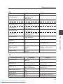
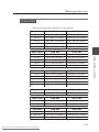
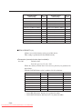
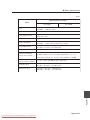
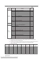
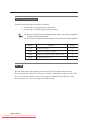
Options
Item
Quantity
Remarks
LP-817 (bucket)
1 unit
LP-819 (carrier sheet set)
1 unit
MF model only
LP-840
(color upgrade kit-S)
1 unit
MF-S model
(North/South America and Europe)
LP-841
(color upgrade kit-L)
1 unit
MF-L model
(North/South America and Europe)
LP-842
(color upgrade kit-S)
1 unit
MF-S model (Asia and Oceania)
LP-843
(color upgrade kit-L)
1 unit
MF-L model (Asia and Oceania)
x
Downloaded From ManualsPrinter.com Manuals
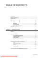
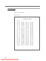
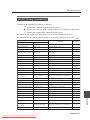
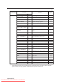
TABLE OF CONTENTS
Introduction .......................................................................................... i
Safety Precautions .............................................................................. ii
Warning labels .................................................................................... v
How to read this manual ................................................................... vii
Manual make-up ................................................................... vii
Notation method ................................................................... viii
Markings ............................................................................... viii
DSCAN format ...................................................................... viii
Key/LCD/LED notations ........................................................ ix
Supplied components ......................................................................... x
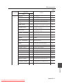
Chapter 1 Getting started
1-1
Features ........................................................................................... 1-2
Operating conditions ........................................................................ 1-4
Environmental conditions .................................................... 1-4
Installation space ................................................................. 1-6
Usable paper ....................................................................... 1-7
Spool memory configuration .............................................. 1-10
The names and functions of each part .......................................... 1-11
Front .................................................................................. 1-11
Right side/rear side ........................................................... 1-12
Interior ............................................................................... 1-13
Control panel ..................................................................... 1-14
How to read the status displays for this device .............................. 1-17
CONTENTS-1
Downloaded From ManualsPrinter.com Manuals
Chapter 2 Basic operations
2-1
Plotting procedures overview ........................................................... 2-3
Turning the power on and off ........................................................... 2-3
Power on ............................................................................. 2-4
Power off ............................................................................. 2-6
Installation operations ...................................................................... 2-7
Online and offline ........................................................................... 2-10
Online ................................................................................ 2-10
Offline ................................................................................ 2-10
Replacing paper rolls ..................................................................... 2-11
Precautions during replacement ........................................ 2-13
How to detach the paper rolls ............................................ 2-14
How to attach the paper roll .............................................. 2-16
Replacing the toner ........................................................................ 2-19
Precautions on handling .................................................... 2-20
Toner replacement procedures .......................................... 2-21
Replacing the waste toner bottle ................................................... 2-24
Precautions during replacement ........................................ 2-24
Waste toner bottle replacement procedures ...................... 2-25
Replacing the process cartridge .................................................... 2-28
Precautions during replacement ........................................ 2-28
Process cartridge replacement procedures ....................... 2-29
CONTENTS-2
Downloaded From ManualsPrinter.com Manuals
Manual paper feeding (cut paper) .................................................. 2-34
Manual feeding procedures ............................................... 2-34
Manual paper feeding procedure ...................................... 2-35
Pause, continue, cancel (and additional printing) .......................... 2-39
Print stop ........................................................................... 2-39
Continue printing ............................................................... 2-39
Cancel printing ................................................................... 2-40
Additional printing .............................................................. 2-40
Web function .................................................................................. 2-41
Functions ........................................................................... 2-41
Web function startup method ............................................. 2-42
Cleaning the exterior ...................................................................... 2-43
Using paper of new standard series .............................................. 2-44
Using paper of Chinese standard series ........................................ 2-46
Limiting rolls to be used ................................................................. 2-48
Chapter 3 Menu overview
3-1
Channels and ports .......................................................................... 3-3
Data formats .................................................................................... 3-3
Data formats which can be used ......................................... 3-3
Data format auto-judging ..................................................... 3-3
CONTENTS-3
Downloaded From ManualsPrinter.com Manuals
Jobs ................................................................................................. 3-4
Reprinting ............................................................................ 3-4
Settings menu .................................................................................. 3-5
PDL menu ........................................................................................ 3-8
When using our company’s printer driver ............................ 3-8
Items which you can set .................................................................. 3-9
Idle status ............................................................................ 3-9
Printing status .................................................................... 3-11
Menu screen .................................................................................. 3-11
Setup menu “SETUP” ........................................................ 3-11
Device menu “DEVICE” ..................................................... 3-12
Paper menu “PAPER” ........................................................ 3-13
Function menu “FUNCTION” ............................................. 3-14
Protocol menu “PROTOCOL” ............................................ 3-15
Reset menu “RESET” ........................................................ 3-16
System menu “SYSTEM” .................................................. 3-17
Chapter 4 Basic Menu Operation
4-1
Summary of basic menu operation .................................................. 4-2
Offline menu operation .................................................................... 4-3
Switching the menu on the same hierarchy ........................ 4-3
Moving the menu hierarchy ................................................. 4-4
Setting or changing the parameters .................................... 4-5
Exiting the setting .............................................................. 4-10
CONTENTS-4
Downloaded From ManualsPrinter.com Manuals
Chapter 5 "SETUP" Menu
5-1
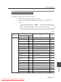
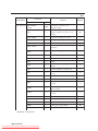
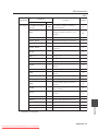
Setting parameter items ................................................................... 5-2
Setup menu setting parameter table ................................... 5-3
Setup parameter priority mode .......................................... 5-10
PARAMETER MODE (DSCAN only) ................................. 5-11
MEDIA SERIES (HP-GL, TIFF, CALS only) ...................... 5-11
AUTO SUPPLY ................................................................. 5-12
FIXING MODE ................................................................... 5-13
COPY COUNT ................................................................... 5-14
SUPPLY PARAM. .............................................................. 5-15
DRAWING PARAM. .......................................................... 5-17
SCALING PARAM. ............................................................ 5-21
FORMAT PARAM. (HP-GL DSCAN only) ......................... 5-24
PEN PARAMETER (HP-GL DSCAN only) ........................ 5-29
RASTER PARAM .............................................................. 5-34
Chapter 6 "DEVICE" menu
6-1
Setting items .................................................................................... 6-2
POWER SAVE .................................................................... 6-3
EDGE CUT TIMER .............................................................. 6-4
DOOR OPEN CUT .............................................................. 6-5
DENSITY ............................................................................. 6-5
TRACING PAP. MODE ....................................................... 6-5
BOTTLE MODE ................................................................... 6-6
CONTENTS-5
Downloaded From ManualsPrinter.com Manuals
Chapter 7 "PAPER" menu
7-1
Setting items .................................................................................... 7-2
MEDIA TYPE ....................................................................... 7-2
MEDIA SERIES ................................................................... 7-3
Chapter 8 "FUNCTION" menu
8-1
Setting items .................................................................................... 8-2
MENU PRINT ...................................................................... 8-3
HPGL SELF PLOT .............................................................. 8-5
DSCAN SELF PLOT ........................................................... 8-6
ERROR LOG ....................................................................... 8-7
JOB LOG ............................................................................. 8-8
ENGINE LOG .................................................................... 8-10
SYSTEM DATE ................................................................. 8-11
SYSTEM TIME .................................................................. 8-11
INIT CHARG. INF .............................................................. 8-11
PRINT CHARG. INF .......................................................... 8-11
MAINTE INFO ................................................................... 8-12
DATA DUMP ..................................................................... 8-12
Chapter 9 "PROTOCOL" menu
9-1
Setting items .................................................................................... 9-2
PDL SELECT....................................................................... 9-3
XPT PORT .......................................................................... 9-4
PRINTER NAME ................................................................. 9-4
USER NAME ....................................................................... 9-5
CONTENTS-6
Downloaded From ManualsPrinter.com Manuals
Chapter 10 "RESET" menu
10-1
Reset functions .............................................................................. 10-2
SYSTEM RESET ............................................................... 10-2
PORT RESET ................................................................... 10-3
Chapter 11 "SYSTEM" menu
11-1
Setting items .................................................................................. 11-2
Communication parameter "COMM. PARAM" .................. 11-3
WEB LOCK ....................................................................... 11-5
ENABLE SERIES .............................................................. 11-6
APPLY ROLL .................................................................... 11-8
CHINA SIZE .................................................................... 11-10
INITIAL SET .................................................................... 11-11
LANGUAGE ..................................................................... 11-12
LENGTH UNITS .............................................................. 11-12
ADMIN PASSWORD ....................................................... 11-12
Chapter 12 Ethernet parameter "ETHERNET"
12-1
Setting items .................................................................................. 12-2
PORT SELECT ................................................................. 12-4
DHCP ................................................................................ 12-4
IP ADDRESS ..................................................................... 12-5
SUBNET MASK ................................................................. 12-5
ROUTING TABLE .............................................................. 12-6
SETUP DETAILS .............................................................. 12-7
CONTENTS-7
Downloaded From ManualsPrinter.com Manuals
Chapter 13 Terioplot
13-1
About Terioplot .............................................................................. 13-2
Terioplot Hardware Requirements ................................................. 13-3
Settings .......................................................................................... 13-4
Restrictions .................................................................................... 13-5
Chapter 14 Troubleshooting
14-1
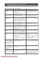
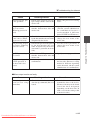
Troubleshooting ............................................................................. 14-2
When an error message appears .................................................. 14-3
Paper Jam ......................................................................... 14-3
Door Open ....................................................................... 14-14
Operator Call ................................................................... 14-16
Warning ........................................................................... 14-17
Service Call Errors .......................................................... 14-25
Error log ....................................................................................... 14-29
Classification of Error/Warning ........................................ 14-29
Format of Message ......................................................... 14-29
Log Registration Format .................................................. 14-30
Type of Error Log ............................................................ 14-31
Error Log Classification Table ......................................... 14-33
Troubleshooting for ethernet ........................................................ 14-34
If "BOTTLE MAINT. STARTS" appears ....................................... 14-36
CONTENTS-8
Downloaded From ManualsPrinter.com Manuals
When a print error occurs ............................................................ 14-37
When there is an abnormal sound ............................................... 14-38
Appendix
Appendix-1
Basic specifications ............................................................ Appendix-2
Plotter Specification ................................................ Appendix-2
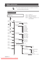
Menu structure .................................................................... Appendix-4
[SETUP] MENU ...................................................... Appendix-4
[DEVICE] MENU .................................................. Appendix-10
[PAPER] MENU .................................................... Appendix-11
[FUNCTION] MENU ............................................. Appendix-12
[PROTOCOL] MENU ............................................ Appendix-13
[RESET] MENU .................................................... Appendix-14
[SYSTEM] MENU ................................................. Appendix-15
Command list .................................................................... Appendix-21
HP-GL,HP-GL/2 Device Control Command List ... Appendix-21
HP-GL,HP-GL/2 Device Plotting Command List .. Appendix-22
HP RTL Plotting Command List ........................... Appendix-25
D-SCAN Format Command List ........................... Appendix-27
TIFF Tag ............................................................... Appendix-33
CALS Format Records ......................................... Appendix-34
ftp Tag .................................................................. Appendix-34
lpd Support Commands ........................................ Appendix-36
xpt(socket I/F) ....................................................... Appendix-36
CONTENTS-9
Downloaded From ManualsPrinter.com Manuals
Downloaded From ManualsPrinter.com Manuals
Getting started
Chapter 1 provides necessary information to operate this device. Read
this chapter to understand the basics of this device before proceeding to
the following chapters.
Contents of this chapter
Features
Operating conditions
The names and functions of each part
How to read the status displays for this device
1-1
Downloaded From ManualsPrinter.com Manuals
Chapter 1 Before using this device
Chapter 1
Features
This device is an electrophotographic black-and-white raster plotter
which produces plots by receiving graphic data created by a work station
or PC (hereafter referred to as a computer.)
This device is equipped with the following features:
High speed plotting
output, high resolution
This device has 80 mm (3.15 inches)/sec recording speed and
can output A0 size drawings at 3.4 sheets per minute. It can also
output high accuracy drawings at 600 dpi resolution.
2-roll paper feeding
mechanism, long drawing
compatible
This device employs a 2-roll paper feeding mechanism that sets
2 sizes from a choice of 4 sizes: A0 size (or 36 inch size), A1 (or
24 inch size), A2 (or 18 inch size), and A3 (or 12 inch size). By
employing paper rolls compatible with drawing sizes ranging
from A0 to A4, a low running cost is achieved by reducing paper
consumption.
This device can also output 2.5 m / 98.4 inch size (10 m / 393.7
inch for the LP-1020L) long sheet drawings. The maximum
plotting range of this device is as follows:
(Note)
Picture quality and printing accuracy can only be assured for plain paper
and recycled paper. (Only up to twice the length of the standard-size
paper can be assured for tracing paper and film.)
LP-1020
• A0 size paper roll : 841 × 2500 mm (33.1 × 98.4 inches)
• A1 size paper roll : 594 × 1830 mm (23.4 × 72 inches)
• A2 size paper roll : 420 × 1200 mm (16.5 × 47.2 inches)
• A3 size paper roll : 297 × 920 mm (11.7 × 36.2 inches)
LP-1020L
• A0 size paper roll : 841 × 10,000 mm (33.1 × 393.7 inches)
• A1 size paper roll : 594 × 10,000 mm (23.4 × 393.7 inches)
• A2 size paper roll : 420 × 1220 mm (16.5 × 47.2 inches)
• A3 size paper roll : 297 × 920 mm (11.7 × 36.2 inches)
1-2
Downloaded From ManualsPrinter.com Manuals
▼Features
This device is equipped with a manual feeding print function.
(Note)
The picture quality and printing accuracy for manually fed printing cannot
be assured.
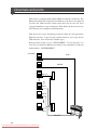
Multiport interface
The device is equipped with an Ethernet interface and allows for
network connection to network. It can also be equipped with
both parallel interface and USB interface. In addition, 10 logical
ports can be used for the Ethernet interface, which then allows
up to 12 computers, including parallel interface and USB
interface, to be simultaneously connected.
Supports a variety of
paper types
4 types of rolls—paper, recycled paper, tracing paper, and
film—are supported.
Front paper feeding/
finished drawing outlet
The device has a front paper feeding and finished drawing outlet
structure. This allows for paper to be loaded and output drawings
to be processed only at the front of the device. This means that
the device requires only a small installation space.
The device was designed for simple, front operation, allowing
paper to be loaded and toner cartridges to be replaced with ease.
1-3
Downloaded From ManualsPrinter.com Manuals
Chapter 1 Before using this device
Manual feeding
mechanism
Operating conditions
This section covers operating conditions of this device including
environmental conditions, installation space, supported papers and spool
memory configuration.
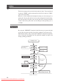
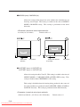
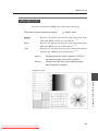
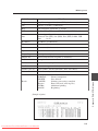
Environmental conditions
This device should be used within the temperature and humidity ranges
indicated in the graph below.
◆ To obtain the best picture quality, use the device within a
temperature and humidity range of 20 to 30°C, 45 to 60%RH.
(relative humidity)
■Operating temperature and humidity range
80%RH
(×103Pa)
5
4
(50%RH)
28°C, 80%RH
Vapor
pressure
3
35°C, 48%RH
Operating temperature and
humidity range
2
35°C
20%RH
1
15°C
0
10
20
Temperature
1-4
Downloaded From ManualsPrinter.com Manuals
30
40 (°C)
▼Operating conditions
Chapter 1 Before using this device
Do not install the plotter in the following places:
◆ Places exposed to direct sunlight
◆ Places subject to vibration
◆ Places with excessive dust
◆ Places subject to extreme changes in temperature or humidity
◆ Places near an air conditioner or a heater
◆ Places where the plotter may get wet
◆ Places subject to direct air flow from a vent
◆ Places near a diazo copier that may generate ammonia gas
◆ Places with poor ventilation
1-5
Downloaded From ManualsPrinter.com Manuals
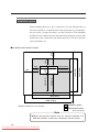
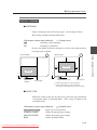
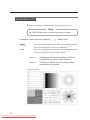
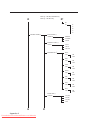
Installation space
When installing this device, space to the front, rear, left and right sides of
the device should be accommodated for the replacement of consumables,
the processing of output drawings, and the ventilation. The minimum
installation space indicated in the diagram below should be ensured. The
maintenance space indicated in the diagram below is needed to perform
parts replacement, etc.
700 (27.6)
1652 (65)
600 (23.6)
2052 (80.8)
1154
(45.4)
900 (35.5)
800 (31.5)
700
(27.6)
300
(11.8)
552
(21.7)
300
(11.8)
600
(23.6)
■Installation/maintenance space
2054 (80.9)
2554 (100.6)
Installation space
(Height is 2000 mm / 78.7 inches)
Maintenance space
Note
units: mm (inch)
◆When moving this device from its current location to a
different location, contact our company’s service center.
1-6
Downloaded From ManualsPrinter.com Manuals
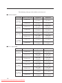
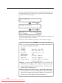
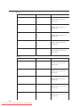
Supported
Use roll paper specified by our company as indicated below:
Note
◆If paper not specified by our company is used, picture quality
cannot be assured. Moreover, the device may malfunction.
■Roll paper specified by our company
Part No.
Paper type & size
LP-733
LP-780
LP-788
A0 size width (841 mm / 33.1 inches)
Plain paper
(67g / m2)
A1 size width (594 mm / 23.4 inches)
A2 size width (420 mm / 16.5 inches)
LP-781
A3 size width (297 mm / 11.7 inches)
LP-735
A0 size width (841 mm / 33.1 inches)
LP-782
LP-740
Tracing paper
(75g / m2)
A1 size width (594 mm / 23.4 inches)
A2 size width (420 mm / 16.5 inches)
LP-783
A3 size width (297 mm / 11.7 inches)
LP-744
A0 size width (841 mm / 33.1 inches)
LP-786
LP-743
Mat film
(#300)
A1 size width (594 mm / 23.4 inches)
A2 size width (420 mm / 16.5 inches)
LP-787
A3 size width (297 mm / 11.7 inches)
LP-734
A0 size width (841 mm / 33.1 inches)
LP-947
LP-948
Recycled paper
(66g / m2)
LP-949
A1 size width (594 mm / 23.4 inches)
A2 size width (420 mm / 16.5 inches)
A3 size width (297 mm / 11.7 inches)
1-7
Downloaded From ManualsPrinter.com Manuals
Chapter 1 Before using this device
▼Operating conditions
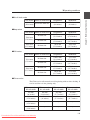
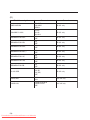
The following roll paper of the widths can be also used.
■9×12 inch series
Roll width Name of fixed form
36 inches
(914.4 mm)
24 inches
(609.6 mm)
18 inches
(457.2 mm)
12 inches
(304.8 mm)
Lengthwise
Widthwise
E-form size
1219.2 mm
(48 inches)
914.4 mm
(36 inches)
D-form size
914.4 mm
(36 inches)
609.6 mm
(24 inches)
D-form size
914.4 mm
(36 inches)
609.6 mm
(24 inches)
C-form size
609.6 mm
(24 inches)
457.2 mm
(18 inches)
C-form size
609.6 mm
(24 inches)
457.2 mm
(18 inches)
B-form size
457.2 mm
(18 inches)
304.8 mm
(12 inches)
B-form size
457.2 mm
(18 inches)
304.8 mm
(12 inches)
A-form size
304.8 mm
(12 inches)
228.6 mm
(9 inches)
Lengthwise
Widthwise
E-form size
1117.6 mm
(44 inches)
863.6 mm
(34 inches)
D-form size
863.6 mm
(34 inches)
558.8 mm
(22 inches)
D-form size
863.6 mm
(34 inches)
558.8 mm
(22 inches)
C-form size
558.8 mm
(22 inches)
431.8 mm
(17 inches)
C-form size
558.8 mm
(22 inches)
431.8 mm
(17 inches)
B-form size
431.8 mm
(17 inches)
279.4 mm
(11 inches)
B-form size
431.8 mm
(17 inches)
279.4 mm
(11 inches)
A-form size
279.4 mm
(11 inches)
215.9 mm
(8.5 inches)
■8.5×11 inch series
Roll width Name of fixed form
34 inches
(863.6 mm)
22 inches
(558.8 mm)
17 inches
(431.8 mm)
11 inches
(279.4 mm)
1-8
Downloaded From ManualsPrinter.com Manuals
▼Operating conditions
Roll width Name of fixed form
Lengthwise
Widthwise
30 inches
30× 42 size form size
(762.0 mm)
1066.8 mm
(42 inches)
762.0 mm
(30 inches)
Roll width Name of fixed form
Lengthwise
Widthwise
B1 form size
1000.0 mm
(39.4 inches)
700.0 mm
(27.6 inches)
B2 form size
700.0 mm
(27.6 inches)
500.0 mm
(19.7 inches)
B2 form size
700.0 mm
(27.6 inches)
500.0 mm
(19.7 inches)
Lengthwise
Widthwise
B1 form size
1000.0 mm
(39.4 inches)
707.0 mm
(27.8 inches)
B2 form size
707.0 mm
(27.8 inches)
500.0 mm
(19.7 inches)
B2 form size
707.0 mm
(27.8 inches)
500.0 mm
(19.7 inches)
B3 form size
500.0 mm
(19.7 inches)
353.0 mm
(13.9 inches)
Chapter 1 Before using this device
■30×42 inch series
■Map series
700.0 mm
(27.6 inches)
500.0 mm
(19.7 inches)
■DIN series
Roll width Name of fixed form
707.0 mm
(27.8 inches)
500.0 mm
(19.7 inches)
■China series
The China series roll cannot be used for plotting with cut sheet feeding. It
can be used for real size plotting only.
Chinese series
A0 roll width
Chinese series
A1 roll width
Chinese series
A2 roll width
Chinese series
A3 roll width
914 mm
(36 inches)
620 mm
(24.4 inches)
450 mm
(17.7 inches)
310 mm
(12.2 inches)
910 mm
(35.8 inches)
610 mm
(24 inches)
440 mm
(17.3 inches)
297 mm
(11.7 inches)
900 mm
(35.4 inches)
-
-
-
880 mm
(34.6 inches)
-
-
-
1-9
Downloaded From ManualsPrinter.com Manuals
Paper storing precautions are as follows:
Notes
◆Store the paper in a cool dark place with in the specified
humidity ranges.
◆Store the paper in it’s packaging material so that dust will not
accumulate on the paper.
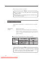
Spool memory configuration
Spool memory configurations are available for this device as specified
below.
Expansion kit
LP-815
Extends spool memory.
Spool memory is the memory needed to receive plotting data.
If plots cannot be produced normally due to spool memory
shortage, installing the following options allows plots to be
produced normally.
■Spool memory configuration when LP-815 is installed
Note
◆The maximum capacity to be actually spooled is slightly
different from the values indicated in the above table.
Confirm the capacity by executing “MENU PRINT.”
1-10
Downloaded From ManualsPrinter.com Manuals
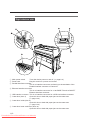
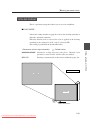
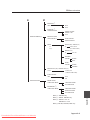
This section explains the names, usage information, and functions of each
part of this device.
Front
1 Roll 1 drawer (door 1)
Install paper roll. (⇒ page 2-11)
2 Roll 2 drawer (door 2)
Install paper roll. (⇒ page 2-11)
3 Manual feed drawer (door 4)
Open this drawer when a paper jam occurs during
manual feeding. (⇒ page 14-3)
4 Finished drawing outlet Drawings exit from here.
5 Top cover (door 6)
Open this cover when a paper jam occurs near the top door.
(⇒ page 14-3)
6 Fixation door (door 7)
Open this door when a paper jam occurs in the vicinity of the finished
drawing outlet. (⇒ page 14-3)
7 Manual paper feeding guide (door 8)
Open this door when feeding the paper manually. (⇒ page 2-34)
8 Manual feed inlet
Insert paper from this inlet during manual feeding. (⇒ page 2-34)
9 Toner cover
Open this cover when replacing toner. (⇒ page 2-19)
0 Control panel
The LEDs and LCD which indicate device status and the keys to set
various functions are laid out here. (⇒ page 1-14)
A Waste toner door
Open this door to replace a waste toner bottle. (⇒ page 2-24)
1-11
Downloaded From ManualsPrinter.com Manuals
Chapter 1 Before using this device
The names and functions of each part
Right side/rear side
1 Main power switch
Turns the device power on and off. (⇒ page 2-3)
2 Power cord
Plug this cord into a power cord socket.
3 Parallel interface connector
This is an interface connector conforming to the standards of the
Parallel interface connector of Centronix.
4 Ethernet interface connector
This is an interface connector for a 100 BASE-TX and 10 BASE-T
Ethernet interface connector.
5 USB interface connector This is an interface connector for a USB 2.0 interface connector.
6 Cutter door (door 5)
Open this door to deal with paper jams at the cutter area.
(⇒ page 14-3)
7 Cutter door inside (door 9)
Open this door to deal with paper jams at the cutter area.
(⇒ page 14-3)
8 Cutter door lower small door (door 10)
Open this door to deal with paper jams at the cutter area.
1-12
Downloaded From ManualsPrinter.com Manuals
▼The names and functions of each part
1 Paper feed knob
2 Paper flange
Chapter 1 Before using this device
Interior
Feeds the end of the roll to the paper feed inlet. (⇒ page 2-11)
This flange is attached to the roll paper. (⇒ page 2-11)
1-13
Downloaded From ManualsPrinter.com Manuals
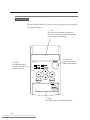
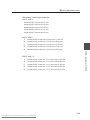
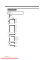
Control panel
The keys, LEDs and LCD are laid out on the control panel as illustrated in
the following diagram.
2 LCD
The status of this device, as well as a
menu to set the device functions appears
on a 20-digit, 2-line display.
1 LEDs
The device status is
indicated by LED’s on,
flashing, and off.
4 Power key
Use this key to turn
ON/OFF this device.
3 Keys
Use these keys to set device functions.
1-14
Downloaded From ManualsPrinter.com Manuals
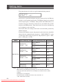
▼The names and functions of each part
Number
Name
Error lamp (red)
Function
Indicates the presence or absence of errors.
On: Error present
Off: No error present
Indicates the amount of remaining toner.
On: There is sufficient toner.
Toner lamp (green) Flashing: Toner is running low.
Off: There is no toner (plots cannot be produced
without replenishment.)
LED’s
Display
Keys
Power
Waste toner lamp
(green)
Indicates the toner waste bottle replacement time.
On: Normal
Flashing: Replacement timing is approaching
Off: Plots cannot be produced without replacement
Process lamp
(green)
Indicates the process cartridge replacement time.
On: Normal
Flashing: Replacement time is approaching
Off: Process cartridge is not installed.
Menu lamp
(green)
Indicates that this device is ready for setting,
receiving data, or printing.
On: Setting operations can be performed
Off: Ready to receive data and print.
LCD
Displays a variety of messages in a 20-figure and 2line display to inform you of the device status.
MENU key
Switches the status of the device from setting ready
status to data receive and print ready status.
ENTER key
Inputs the parameters.
CANCEL key
Cancels parameter input.
Key
Switches menu items and changes parameters.
Key
Switches menu items and changes parameters.
Key
Switches menu items/hierarchy and changes.
Key
Switches menu items/hierarchy and changes.
Power key
Turns the device power on and off.
1-15
Downloaded From ManualsPrinter.com Manuals
Chapter 1 Before using this device
LCD, LEDs, and key functions
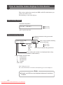
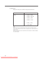
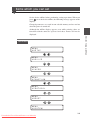
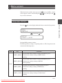
How to read the status displays for this device
This section explains the control panel LEDs and LCD which inform you
of the status of the device.
The following are the main displays.
Data standby display
Standard configuration
PR I NT
READY
Error lamp
Menu lamp
This is a print ready status.
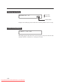
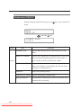
Data processing display
Indicates that data is being processed.
(flashing)
✽S0 0 1
J009
PROC E S S I NG
F 0 1 HPGL
PDL name
HPGL
DSCAN
TIFF
CALS
Sxxx: The job number standing
by for processing
Error lamp
Menu lamp
Jxxx: The job number being processed
Port number (this number is not displayed when using
parallel or USB interface.)
Communication channel name
F
: FTP protocol
L
: LPD protocol
X
: XPT protocol
PR : Parallel
USB : USB
Data is being processed.
The various information for the data currently being processed is displayed.
Note
◆Parallel and USB are only displayed when each interface is
installed.
1-16
Downloaded From ManualsPrinter.com Manuals
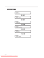
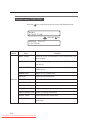
▼How to read the status displays for this device
PR I NT
F 0 1 HPGL
0 2 / 9 9✽S0 0 1
J009
Chapter 1 Before using this device
Printing in progress display
Error lamp
Menu lamp
Scheduled number of prints
Number of prints executed
Data is being printed.
The various information for the data currently being printed is displayed.
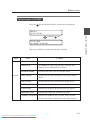
Print information display
TOTA L
TOTA L
COUN T
RUN ( m )
mmmmmm
mmmmmm
Error lamp
Menu lamp
is pressed in data standby or print ready status.
This display appears when
The total number of prints and the length of media printed appear.
◆ Many of our customers who have signed a maintenance
agreement regularly telephone our service center for
assistance. When contacting our service center, please make
a note of this information for your reference.
◆ This display appears for approximately three seconds, after
which the display will automatically return to the original data
standby display condition.
Setting ready display
Error lamp
MENU
# SETUP
Menu lamp
The functions for this device can be set. ⇒ chapter 3
Error display
C LOSE
DOOR 1
Error lamp
Menu lamp
An error has occurred.
Errors are classified according to those which can be dealt with by the operator, or
errors which can only be dealt with by your dealer or our service center, etc. ⇒
Chapter 14
1-17
Downloaded From ManualsPrinter.com Manuals
Warming up display
WA RM I N G
UP
nnn
Error lamp
Menu lamp
Counts down
Displays the warming-up status and the time remaining until the device is ready.
Power saving display
P OW E R
S A V I NG
This display appears when the device enters the power saving mode after the data
standby status has continued for a certain period of time.
1-18
Downloaded From ManualsPrinter.com Manuals
Basic operations
Chapter 2 describes basic operating procedures for this device such as
turning the power on and off, replacing paper, and replacing toner will be
explained.
Contents of this chapter
Plotting procedures overview
Turning the power on and off
Installation operations
Online and offline
Replacing paper rolls
Replacing the toner
Replacing the waste toner bottle
Replacing the process cartridge
Manual paper feeding (cut paper)
Pause, continue, cancel, and additional printing
Web function
Cleaning the exterior
Using paper of new standard series
Using paper of Chinese standard series
Limiting rolls to be used
2-1
Downloaded From ManualsPrinter.com Manuals
Chapter 2 Basic operations
Chapter 2
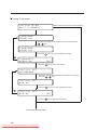
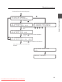
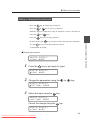
Plotting procedures overview
Plotting is usually conducted in accordance with the following
procedures.
For information on computer operations, refer to your computer manual.
1
Turn on the power for the computer and this device.
For information on turning on the device power, refer to “Turning the
power on/off” (⇒ page 2-3)
2
Confirm the status of the device on the control panel.
Confirm that the LEDs are not indicating abnormalities and that the LCD
indicates Data standby status.
Press
when the Menu lamp is on.
When the Toner lamp is flashing or off, replace the toner. (⇒ page 2-19)
When the Toner waste bottle lamp is flashing or off, replace the waste
bottle. (⇒ page 2-24)
When the Process lamp is flashing or on, replace the process cartridge.
(⇒ page 2-28)
When the Error lamp is on, refer to chapter 14 for information on
troubleshooting.
3
Open your application software on your computer and
create a drawing.
If the device settings do not conform to the application software you are
using, reset the settings for this device (⇒ Chapters 5 to 12).
4
Send the data from the computer to this device.
2-2
Downloaded From ManualsPrinter.com Manuals
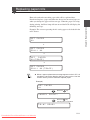
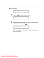
Turning the power on and off
Notes
◆While data is being processed, do not turn off the main
power switch. Doing so may damage the system.
◆When the power is on and the Main power switch is turned
off, or when the power goes out due to blackout etc.,
restoring the power (turning the Main power switch back on
or resetting from a blackout) is the first step, but will not turn
the plotter on. You must also turn ON the power key on the
control panel.
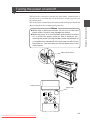
Main power switch
Control panel
Power key
2-3
Downloaded From ManualsPrinter.com Manuals
Chapter 2 Basic operations
This device has two power switches: the main power switch located at
the lower-left as seen from the rear of the device; and the power key on
the control panel.
The device power is turned on by first turning on the main power switch, and
then pressing the device’s control panel power key.
Power on
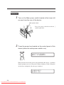
1
Turn on the Main power switch located at the lower-left
as seen from the rear of the device.
Main power switch
Press the power switch toward the ⎪
symbol (upwards).
2
Press the power key located on the control panel of this
device (when the main power switch is on).
I N I T I A L I Z I NG
WA I T A MOM E N T
When you first turn on the power after purchasing this device, a guidance
display prompts you to set the panel's display language. If this setting has
already been completed, this message is omitted.
L ANGU AGE ?
✽ ENG L I SH
2-4
Downloaded From ManualsPrinter.com Manuals
▼Turning the power on and off
When a job is saved, the following message appears and the device stands
by for selection.
DE L E T E J OB ?
Y=ENTER
N=CANCE L
If a key input is not made,
this message will time-out
after about 10 seconds
and the device starts up
with the job in saved
condition.
Under normal conditions, the display reads “INITIALIZING STANDBY”
and is changed to the following message.
S Y S T EM
01A
V ERS I ON
The message is changed to the “WARMING UP".
WA RM I N G
UP
nnn
Warm up will take about 4
minutes. (about 8 minutes
with LP-1020L)
nnn: a count down for the
warm up is displayed.
The message indicates that the device is now online (“PRINT READY”).
P R I NT
READY
A “PRINT READY” message indicates that the device is functioning
normally.
2-5
Downloaded From ManualsPrinter.com Manuals
Chapter 2 Basic operations
When a job is not saved, this message is omitted.
Power off
When turning the power off, confirm that the device is in the data receive
standby mode.
1
Press the Power key on the device panel for about 1
second.
Release the key when the display reads "SHUTTING
DOWN."
When a job is present, it is automatically saved and will be printable the
next time you turn the power on.
(Only when HDD is installed)
Note:
Even when “SHUTTING DOWN” appears, the
power will not turn off until you release the
power key.
S H U T D OW N
WA I T A MOM E N T
This indicates that the
device is executing a shut
down.
When the shut down process has been completed, the power will turn off.
2
Turn the main power off when you are not using this
device for an extended period of time.
Main power switch
Press the power switch toward the
(downwards).
2-6
Downloaded From ManualsPrinter.com Manuals
symbol
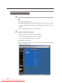
When you first turn on the power after purchasing this device, it will start
up differently from how it will regularly start up thereafter. A guidance
display will prompt panel display language selection, initializing of
parameters appropriate for your region, and the setting of an IP address.
By setting this IP address when the plotter is installed, you will be able to
utilize the browser of a host computer on the same network as the plotter
to make various settings.
Moreover, when using the network to operate the device, you must also
initialize the following plotter settings from the browser or the device
panel. If you neglect to set these settings, connection with the router will
not be possible.
1 Subnet mask settings
2 Routing table settings
Once you set the panel display language selection, initialized optimal
setup parameters according to your region, and set IP address settings,
this guidance display will not appear the next time the power is turned on.
When “INITIALIZE” is executed in the System menu (explained later),
the IP address will return to an unset condition, and the IP address setting
guidance display will appear once again when the power is turned on.
Notes
◆The panel display language selection allows you to select
the language which will appear on the device control panel,
and can also be set from “LANGUAGE” in the System menu.
◆Initializing of the optimal parameters for your region for such
items as media series can also be set from “INITIALIZE” in
the System menu.
◆The IP address is a communication parameter during
Ethernet connection which is assigned specifically to each
device.
2-7
Downloaded From ManualsPrinter.com Manuals
Chapter 2 Basic operations
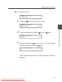
Installation operations
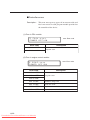
■Turning on the power
When a language has already been selected.
I N I T I A L I Z I NG
WA I T A MOM E N T
L A NGUAGE ?
✽ E NG L I SH
Select the language to be displayed on the panel using the
,
keys.
L ANGU AGE ?
✽ ENG L I S H
Press the
L A NGUAGE ?
✽ E NG L I SH
key to go to the confirmation screen.
OK ?
Press the
key to choose this setting.
I N I T I AL SET
✽S T ANDARD
Select the optimal setup parameters according to your region
using the
,
keys.
I N I T I AL
✽CH I NA
SET
Press the
I N I T I AL
✽CH I NA
key to go to the confirmation screen.
SET
OK ?
Press the
Proceed to the next page
2-8
Downloaded From ManualsPrinter.com Manuals
key to determine this setting.
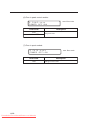
▼Installation operations
Continued from the preceding page
Press the
Chapter 2 Basic operations
U S I N G N E T WO R K ?
Y = ENT ER N=CANCE L
key.
I P ADDRESS ?
✽000 . 000 . 000 . 000
D I S P L A Y I NG N E X T ?
Y = ENT ER N= CANCE L
Input the values using the
keys.
,
,
,
,
I P ADDRESS ?
✽ 1 9 2 .1 6 8 . 1 2 3 . 1 2 3
Press the
screen.
I P ADDRESS ?
✽ 1 9 2 .1 6 8 . 1 2 3 . 1 2 3
Press the
key to go to the confirmation
OK ?
key to determine the selection.
The device will be automatically
rebooted.
S Y S T EM
01A
PR I NT
V ERS I ON
READY
2-9
Downloaded From ManualsPrinter.com Manuals
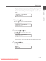
Online and offline
The device is “ONLINE” when it can receive and print data from the host
computer and is “OFFLINE” when settings are being input on the control
panel. You must set the device to “offline” to operate the menu from the
control panel.
Online
To print from the host computer, the device must be online. Always make
sure that the device is online to print from the host computer. If the device
is not online, follow the procedures below to set the device online. The
device will automatically go online when the device power is turned on.
1
Press the
PR I NT
key to turn the Menu lamp off.
READY
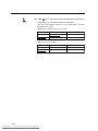
Offline
To select menu operations and paper feed method etc. using the device
control panel, the device must be offline. Before using the control panel
keys, set the device offline according to the following procedures.
1
Press the
MENU
# SETUP
2-10
Downloaded From ManualsPrinter.com Manuals
key to turn the Menu lamp on.
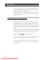
How to detach and reattach the paper rolls will be explained here.
Detach and replace a paper roll when the device has run out of paper or
when you change the paper roll size on type. When the paper is used up
during printing, the Error lamp will turn on and the LCD will display the
following message:
Example: The screen requesting the A3 tracing paper to be loaded in the
roll 1 drawer.
SET
A0
PAPER
or
SET PAPER
RO L L 1 A 0
or
SET
PAPER
A 0 ( TRACE )
or
SET PAPER
RO L L 1 A 0 ( T RA CE )
◆ When a paper replacement message appears on the LCD, it is
possible to cancel the drawing that you sent to print. Use this
function when you don’t have the required paper.
Example)
SET
A1
PAPER
Press the
CANCE L
key.
PR I NT ?
Press the
key.
*Printing will be cancelled.
PR I NT
READY
2-11
Downloaded From ManualsPrinter.com Manuals
Chapter 2 Basic operations
Replacing paper rolls
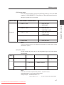
If an error message about paper supply appears on LCD, paper of larger
size than required (or, if a type of paper is specified, paper of different
type) can be chosen for printing.
e.g.
SET
A 1
PAPER
FORCE
Press the
key.
Press the
key.
PR I NT ?
PR I NT
F 0 1 HPGL
0 1 / 0 1✽S0 0 1
J009
*Prints only when paper of larger size than required is available or if
paper of a different type is available.
*Alternative print is disabled, if printing on the manually fed paper.
Notes
◆"A1" in the above example indicates the paper roll width and
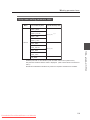
its indication changes as follows:
Example:
A series:
"A0", "A1", "A2", "A3"
9" series:
"36"", "24"", "18"", "12""
8.5" series:
"34"", "22"", "17"", "11""
30x42 series:
"30""
MAP series:
"707 mm", "500 mm"
DIN series:
"707 mm", "500 mm"
Chinese series:
"914 mm", "620 mm", "450 mm"
"310 mm","297 mm"
◆When a paper type is specified as "SET PAPER A0
(TRACE)" and the paper roll is loaded, the display may be
automatically switched to the paper menu. In such a case,
set the type of the paper roll.
◆If the media series is different (that is, appropriate media series
was not loaded into the tray), the display may be automatically
switched to the paper menu when the paper roll is reloaded. In
such a case, set the media series of the paper roll.
2-12
Downloaded From ManualsPrinter.com Manuals
▼Replacing paper rolls
Precautions during replacement
◆The rolls are heavy so be careful not to hurt yourself by
dropping them while you are replacing the rolls.
◆When attaching the rolls, use a cutter to cut the end of the
paper roll. While doing this, take care not to cut yourself or
damage the device.
◆When opening and closing the paper roll drawers, take care
not to get your hands caught in the drawer.
Do not open other paper roll drawers while one paper roll
drawer is open. Doing so will increase your chances of
getting your hands caught in the drawers.
Notes
◆If you change the paper type, you must also change the
device settings accordingly. ⇒ chapter 7
◆Use media types specified by our company.
If you use media types which are not specified by our
company, we cannot assure printing quality.
◆Store the paper in a cool, dark location with low humidity.
2-13
Downloaded From ManualsPrinter.com Manuals
Chapter 2 Basic operations
Caution
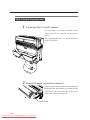
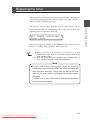
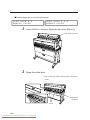
How to detach the paper rolls
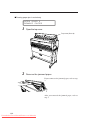
1
Pull out the Roll 1 or Roll 2 drawer.
Use your fingers to grasp the handle in the
center of the drawer and pull the drawer out
gently.
(The diagram indicates a case where the Roll 2
drawer is opened.)
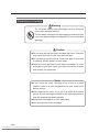
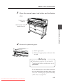
2
Rewind the paper roll and then remove it.
Turn the paper flange in the direction indicated
in the diagram and continue to rewind the roll
until you see the end of roll. Lift up the paper
flange and remove the paper roll.
Paper flange
2-14
Downloaded From ManualsPrinter.com Manuals
▼Replacing paper rolls
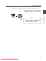
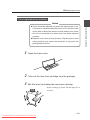
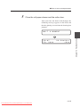
3
Remove the paper flange and take out the paper roll.
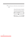
C L OS
E
O
P E N
Note
Knob
◆Take care not to use excessive force
when you turn the paper flange knobs.
The flange ends may come off.
2-15
Downloaded From ManualsPrinter.com Manuals
Chapter 2 Basic operations
Loosen the paper flange by turning the knobs in
the “OPEN” direction and remove both ends of
the paper flange.
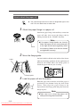
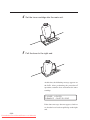
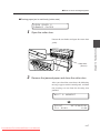
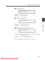
How to attach the paper roll
◆ The paper flange ends do not have a designated right or left
side. You can attach them to either side.
1
Attach the paper flange to a paper roll.
C L OS
E
O
Note
P E N
Knob
2
Push in the paper flange ends until they contact the
paper roll tube, then secure the flange ends by
turning the knob in the “CLOSE” direction.
◆If the paper flange knobs are loosely
fitted, the paper roll will move adversely
to the right and left and negatively affect
the drawing. Make sure that the knobs
are tightened securely.
Move the flange guide.
the label which is affixed to the inside of the drawer
indicates the flange positions for the application of
different roll widths. Move the flange guide to
match the paper roll size you are using.
Label
C L O
S
E
O
P EN
Flange guide
3
Load the paper roll into the drawer.
Hold the paper roll so that the end of the paper is
positioned at the bottom facing the back of the
device. Then align the paper flange to the
depressions in the flange guide and gently insert the
flange in place.
Note
◆Take care not to drop the paper roll
while performing these activities.
2-16
Downloaded From ManualsPrinter.com Manuals
▼Replacing paper rolls
Insert the end of the paper roll into the paper feed inlet of
the device.
Turn the paper flange and insert the end of the
paper roll so that it is straight. Turn the paper
feed knob so that the end of the paper roll
projects about 10 cm.
Paper feed knob
5
Cut the end of the paper.
While holding the end of the paper roll, cut it off
with the cutter.
The “Paper cutter position” label is affixed to
both ends of the space where the cutter blade
should be inserted. Insert the cutter blade into
the space where the label arrow is pointing.
Slide the cutter blade along the space and cut the
paper.
◆ The paper can be cut cleanly when the
cutter is inserted in a perfectly sideways
direction.
Caution
◆Take care not to hurt yourself and damage the device when
handling the cutter.
◆Handle the cutter blade with care so that you do not break it.
◆When sliding the cutter along the space, take care not to cut
the back of your hand on the sides of the paper tray.
2-17
Downloaded From ManualsPrinter.com Manuals
Chapter 2 Basic operations
4
6
Close the paper roll drawer.
Gently push in the Roll 1 or Roll 2 drawer.
When the paper roll drawer is closed, the following
message appears.
WA I T
A
MOM E N T
(It will take about 30 seconds until paper feeding is ready.)
Note
◆After closing the paper roll drawer, wait until the “WAIT A
MOMENT” message disappears before opening the paper
roll drawer again. As the device initiates a paper detection
just after the paper roll drawer is closed, so opening the
paper roll drawer during this operation may cause a paper
jam.
After the replacement, the device will return to the
status before the paper roll was replaced.
Note
◆If you change the type of paper roll, you must change the
corresponding settings, referring to “Paper settings” (⇒
page 7-2).
2-18
Downloaded From ManualsPrinter.com Manuals
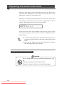
Replacing the toner
When there is no more toner availabe, the Toner lamp will go out, the
Error lamp will come on, and printing will no longer be possible. The
following message appears on the LCD.
S E T TONE R CA R T R I DGE
OPEN L EVER
If the Toner lamp starts flashing or the ERROR message appears, replace
the toner according to the procedures indicated below.
◆ When you open the toner door, you will find a “Toner
replacement” label affixed to the inside surface. Refer to this
when replacing toner.
◆ After the Toner lamp starts flashing, approximately 50 m of
plots can be produce at normal size and density.
Note
◆If plots with a high printing rate—such as drawings
containing many solid print areas and inversed (black and
white inverted) drawings—are printed just before the toner
runs out, the toner may be used up and the device may be
damaged.
To avoid such a case, refill toner as soon as possible when
the toner lamp is flashing.
2-19
Downloaded From ManualsPrinter.com Manuals
Chapter 2 Basic operations
When the toner level runs low, the Toner lamp will flash. Although plots
can still be produced under this condition, obtain a new toner cartridge as
soon as possible and replace the toner.
Precautions on handling
Warning
Do not throw empty toner cartridges into fire. Doing so
may cause accident and fire.
Put the waste cartridge into the wrapping contained in the
toner cartridge package and dispose of it as non-burnable
garbage.
Caution
◆Do not drop and tap the toner cartridge with force. Doing so
may cause the toner to leak from the cartridge.
◆Do not directly touch the toner. If the toner gets on your skin
or clothing, quickly wash it off with water.
◆Take care not to get toner in your eyes or breathe it in. If the
toner gets in your eyes, wash your eyes out with lots of water
and consult your physician.
Notes
◆If you move the toner cartridge from a cold to a warm
location, leave it in room temperature for over three hours
before using it.
◆After replacing the toner, try to use it up within a six month
period. A toner cartridge installed for an extended period of
time will degrade the drawing quality.
◆Keep toner cartridges in a cool, dark place.
◆Use only genuine toner cartridges.
2-20
Downloaded From ManualsPrinter.com Manuals
▼Replacing the toner
Toner replacement procedures
◆Toner should be replaced only when the device power is On.
If the toner is replaced while the power is Off, the device will
not be able to detect the amount of toner and an error status
will not be cancelled even when toner has been replaced
correctly.
◆Replace toner after plotting finishes. Replacing the toner
during plotting may cause the operation to stop and the
plotting data to be lost.
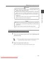
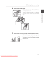
1
Open the toner cover.
2
Take out the new toner cartridge from the package.
3
Mix the toner by shaking the new toner cartridge.
Shake it strongly up, down, left and right, five or
six times.
2-21
Downloaded From ManualsPrinter.com Manuals
Chapter 2 Basic operations
Notes
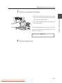
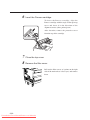
4
Set the toner cartridge into the main unit.
5
Pull the lever to the right end.
At this time, the following message appears on
the LCD. After performing the procedure 6
operation, return the lever and remove the toner
cartridge.
C LOSE L EVER
R E MO V E C A R T R I D G E
If the above message does not appear, check to
see that the lever has been pulled up to the right
end.
2-22
Downloaded From ManualsPrinter.com Manuals
▼Replacing the toner
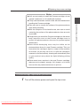
Tap the cartridge to allow toner to drop down.
7
Return the lever to the left.
8
Remove the toner cartridge and close the cover.
Chapter 2 Basic operations
6
At this time, the following message appears on
the LCD.
WA I T
A
MOM E N T
2-23
Downloaded From ManualsPrinter.com Manuals
Replacing the waste toner bottle
When the waste bottle is nearly full with waste toner, the Waste toner
lamp will flash. Although plots can continue to be produced for a little
while longer, replace the waste bottle soon.
When the waste bottle becomes full with waste toner, the Waste toner
lamp will go out. The Error lamp will turn on and plotting will not be
possible. The following message appears on the LCD.
CH ANGE
WA S T E B O T T L E
If the Waste toner lamp starts flashing or the message appears on the
control panel, replace the waste bottle in accordance with the procedures
outlined below.
◆ A “Waste bottle replacement” label is affixed to the side of the
waste toner bottle. Refer to this when replacing the waste
bottle.
◆ Even after the Waste toner lamp starts flashing, you should be
able to produce about 120 m of plots.
Precautions during replacement
Warning
Do not throw waste bottles containing waste toner into
fire.
Doing so may cause an accident and fire.
Dispose of waste bottles as non-burnable garbage.
2-24
Downloaded From ManualsPrinter.com Manuals
▼Replacing the waste toner bottle
◆Do not drop and hit waste bottles containing waste toner.
Doing so may cause toner to leak.
◆Take care not to directly contact the waste toner. If the toner
gets on your skin or clothing, quickly wash it out with water.
◆Take care not to get the waste toner into your eyes or
breathe it in.
If waste toner gets into your eyes, wash your eyes out with
plenty of water and consult a physician.
Notes
◆Replace the waste bottle after plotting has been completed.
If replacement is attempted during plotting, the plotting data
may be lost.
◆The toner inside the waste bottle cannot be re-used.
Waste toner bottle replacement procedures
1
Take out a new waste toner bottle from its package and
remove the cap.
◆ This cap should be used to cover the waste toner bottle which
you are removing, so keep it at hand. ⇒ procedure 4.
2
Open the waste toner bottle door.
The waste bottle door is located at the right side of the device.
2-25
Downloaded From ManualsPrinter.com Manuals
Chapter 2 Basic operations
Caution
3
Remove the waste toner bottle from the main unit.
1 Lift up the waste bottle,
2 Remove it by pulling it out from the bottom
end toward you.
When you have removed the waste toner bottle,
the LCD will display the following message.
SET
WA S T E
4
BOT T L E
Attach the cap to the waste toner bottle.
Cap
Attach the cap which you have removed in
procedure 1 to the waste bottle containing waste
toner.
Dispose of the waste bottle containing waste
toner as non-burnable garbage.
Note
New bottle
Bottle containing
waste toner
2-26
Downloaded From ManualsPrinter.com Manuals
◆Attach the cap securely as it may
come off.
▼Replacing the waste toner bottle
Attach a new waste toner bottle.
1 Insert the mouth of the waste toner bottle
onto the waste toner discharge port of the
main unit by slightly lifting it.
2 Set it onto the bottom surface and position it
so that it is stable.
After the following message appears, the device
status will return to the status before the waste
bottle was replaced.
WA I T
6
A
MO M E N T
Close the waste door.
2-27
Downloaded From ManualsPrinter.com Manuals
Chapter 2 Basic operations
5
Replacing the process cartridge
When the Process cartridge approaches the end of its life, the Process
lamp flashes and the following message appears. It is still possible to
continue to produce plots in this condition, but you must replace the
cartridge soon.
PR I NT READY
R E P L A C E PROC E S S
Note
◆Above message may not appear in certain cases.
If a new process cartridge is not installed soon, the Process lamp goes out,
Error lamp comes on and plotting becomes impossible. The following
error message appears on LCD.
SET
P ROCE S S
C AR T R I DGE
When the Process lamp flashes or goes out, follow the procedures
indicated below to replace the Process cartridge.
Precautions during replacement
Warning
Do not throw the process cartridge into fire. Doing so may
cause accident and fire.
Dispose of process cartridge as non-burnable garbage.
2-28
Downloaded From ManualsPrinter.com Manuals
▼Replacing the process cartridge
◆Until you are ready to install the Process cartridge, do not
unpack it and store it in its cardboard container.
◆Firmly hold the handles on both sides with both hands when
handling the Process cartridge.
◆Take care not to scratch the surface of the photoconductor
drum during handling.
◆With the exception of the handle area, take care to avoid
contacting the surface of the photoconductor drum as much
as possible.
◆Except when you install the Process cartridge into the device
body, keep the cover on the Process cartridge cover to
protect the photoconductor drum and to prevent optical
deterioration.
◆Some black developing toner may be visible on the
photoconductor drum of a new Process cartridge. This is to
ensure that the cartridge is kept in a ready-to-use condition
at all times, so you may use it as it is. After the cartridge is
mounted on the device body, cleaning will automatically start
so you need not worry about the liquid affecting printing
quality.
◆Since waste toner remains in the used Process cartridge,
take care not to shake it strongly, tilt it sharply, or hit it with
force as this may cause waste toner to spill out.
Process cartridge replacement procedures
1
Turn off the device power and open the top cover.
2-29
Downloaded From ManualsPrinter.com Manuals
Chapter 2 Basic operations
Notes
2
Take out the Process cartridge.
Pull the Process cartridge out by holding onto
its handles.
3
Place a new Process cartridge on the top of the device.
1 Remove the Process cartridge from the box
together with its protective case.
2 Place the Process cartridge on the top of the
device together with the protective case.
Two types of filters for replacement use are
contained in the process cartridge packaging
box. Replace the filter after replacing the
process cartridge.
2-30
Downloaded From ManualsPrinter.com Manuals
▼Replacing the process cartridge
4
Remove the orange tape.
A sheet is attached to the tape at (2 points) on
the inside. Remove the sheet together with the
tape.
5
Remove the Process cartridge from its protective case.
While holding onto the handles, open the
protective case while pushing with your thumbs
and remove the Process cartridge from the
protective case.
2-31
Downloaded From ManualsPrinter.com Manuals
Chapter 2 Basic operations
Remove the orange tape affixed to the Process
cartridge (4 points).
6
Insert the Process cartridge.
To insert the Process cartridge, align the
Process cartridge with the angle of the open top
cover and insert it in the direction of the
alignment arrows (three points/green).
After insertion, remove the protective cover
from the top of the cartridge.
7
Close the top cover.
8
Remove the filter cover.
Pull out the filter covers at 2 points on the right
side of the main unit as it faces you, and remove
them.
2-32
Downloaded From ManualsPrinter.com Manuals
▼Replacing the process cartridge
Replace the filter.
Pull out the filters toward you and remove, and
replace with the two filters contained in the
process cartridge packaging box.
10
Attach the filter covers and turn ON the device.
2-33
Downloaded From ManualsPrinter.com Manuals
Chapter 2 Basic operations
9
Manual paper feeding (cut paper)
This device offers a manual feeding feature as a service function.
As this is a service function, we cannot assure the picture quality and
printing accuracy.
Manual feeding procedures
1
Adjust the paper guide.
Adjust the paper guide to the position where
you will set the cut paper for manual feeding.
2
Set the paper so that the printing surface is face down.
When you insert the paper into the manual
paper feed inlet, the paper is drawn in and the
paper is ready for printing.
2-34
Downloaded From ManualsPrinter.com Manuals
▼Manual paper feeding (cut paper)
1
Set the paper feeding mode.
When the PDL setup paper feeding mode is set to the continuous or
optimum mode, paper should be manually fed only for the drawings for
which the data was processed immediately after the paper was fed into the
manual paper feeding unit (this function is called "interrupt manual feeding
function".)
When the PDL setup paper feeding mode is the manual feeding mode,
paper should be always fed from the manual paper feeding unit. If no paper
has been fed into the manual paper feeding unit when data is transferred,
paper to be used is indicated on the operation panel (this function is called
"continuous manual paper feeding function".)
Refer to page 5-12 for details of the paper feeding mode.
2
Load the cut paper.
Cut paper as listed below can be used with this device.
A series fixed form cut paper
Name of fixed
form
Lengthwise length
Widthwise length
A0
1189 mm (46.8 inches)
841 mm (33.1 inches)
A1
841 mm (33.1 inches)
594.5 mm (23.4 inches)
A2
594.5 mm (23.4 inches)
420.5 mm (16.6 inches)
A3
420.5 mm (16.6 inches)
297.3 mm (11.7 inches)
A4
297.3 mm (11.7 inches)
210.3 mm (8.3 inches)
A series width cut paper
Width name
Paper width
A0 width
841 mm (33.1 inches)
A1 width
594.5 mm (23.4 inches)
A2 width
420.5 mm (16.6 inches)
A3 width
297.3 mm (11.7 inches)
Paper length
Max. up to printing length
2-35
Downloaded From ManualsPrinter.com Manuals
Chapter 2 Basic operations
Manual paper feeding procedure
9× 12 series fixed form cut paper
Name of fixed
form
Lengthwise length
Widthwise length
E
1219.2 mm (48 inches)
914.4 mm (36 inches)
D
914.4 mm (36 inches)
609.6 mm (24 inches)
C
609.6 mm (24 inches)
457.2 mm (18 inches)
B
457.2 mm (18 inches)
304.8 mm (12 inches)
A
304.8 mm (12 inches)
228.6 mm (9 inches)
9× 12 series width cut paper
Width name
Paper width
E width
914.4 mm (36 inches)
D width
609.6 mm (24 inches)
C width
457.2 mm (18 inches)
B width
304.8 mm (12 inches)
Paper length
Max. up to printing length
8.5× 11 series fixed form cut paper
Name of fixed
form
Lengthwise length
Widthwise length
E
1117.6 mm (44 inches)
863.6 mm (34 inches)
D
863.6 mm (34 inches)
558.8 mm (22 inches)
C
558.8 mm (22 inches)
431.8 mm (17 inches)
B
431.8 mm (17 inches)
279.4 mm (11 inches)
A
279.4 mm (11 inches)
215.9 mm (8.5 inches)
8.5× 11 series width cut paper
Width name
Paper width
E width
863.6 mm (34 inches)
D width
558.8 mm (22 inches)
C width
431.8 mm (17 inches)
B width
279.4 mm (11 inches)
Paper length
Max. up to printing length
30× 42 series fixed form cut paper
Name of fixed
form
Lengthwise length
Widthwise length
30× 42
1066.8 mm (42 inches)
762.0 mm (30 inches)
30× 42 series width cut paper
Width name
Paper width
Paper length
30"
762.0 mm (30 inches)
Max. up to printing length
2-36
Downloaded From ManualsPrinter.com Manuals
▼Manual paper feeding (cut paper)
Name of fixed
form
Lengthwise length
Widthwise length
B1
1000.0 mm (39.4 inches)
700.0 mm (27.6 inches)
B2
700.0 mm (27.6 inches)
500.0 mm (19.7 inches)
Map series width cut paper
Width name
Paper width
B1 width
700.0 mm (27.6 inches)
B2 width
500.0 mm (19.7 inches)
Paper length
Max. up to printing length
DIN series fixed form cut paper
Name of fixed
form
Lengthwise length
Widthwise length
B1
1000.0 mm (39.4 inches)
707.0 mm (27.8 inches)
B2
707.0 mm (27.8 inches)
500.0 mm (19.7 inches)
B3
500.0 mm (19.7 inches)
353.0 mm (13.9 inches)
DIN series width cut paper
Width name
Paper width
B1 width
707.0 mm (27.8 inches)
B2 width
500.0 mm (19.7 inches)
Paper length
Max. up to printing length
Chinese series width cut paper
Width name
Paper width
914 mm width
914 mm (36 inches)
910 mm width
910 mm (35.8 inches)
900 mm width
900 mm (35.4 inches)
880 mm width
880 mm (34.6 inches)
620 mm width
620 mm (24.4 inches)
610 mm width
610 mm (24 inches)
450 mm width
450 mm (17.7 inches)
440 mm width
440 mm (17.3 inches)
310 mm width
310 mm (12.2 inches)
297 mm width
297 mm (11.7 inches)
Paper length
Max. up to printing length
2-37
Downloaded From ManualsPrinter.com Manuals
Chapter 2 Basic operations
Map series fixed form cut paper
When feeding the cut paper into the manual paper feed inlet, follow the
procedure below (position the cut paper in the center of the manual paper
feed inlet).
When plotting on the fixed form paper, set the paper as shown below (the
paper input direction varies depending on the fixed form paper size).
Set the paper (sideways) in case of:
A4 fixed form cut paper of A series
A fixed form cut paper of 9×12 series
B3 fixed form cut paper of DIN series
A fixed form cut paper of 8.5×11 series
Set other fixed form cut paper
(lengthways)
Manual paper feed inlet
Manual paper feed inlet
Cut paper
Cut paper
When plotting at the actual length or expanded size of a fixed form, load
the paper as shown below (paper should be always set lengthways).
Example of A3 width cut paper
Manual paper feed inlet
Cut paper
After the cut paper is properly fed into the manual paper feed inlet, the
device pulls the paper into it.
Notes
◆When the paper is manually fed, printing is made only on one
sheet of paper even if the number of prints is set to more
than two.
◆Even if the correct size cut paper is not used, printing takes
place when cut paper is fed into the device. In this case, the
drawing may be missing in part.
2-38
Downloaded From ManualsPrinter.com Manuals
Pressing the
key during printing takes the device offline and allows
you to temporarily stop printing by pressing the
key.
Pressing the
key during printing gives you the option to cancel the
drawing being printed.
Pressing the
key during Print stop status allows the device to be
returned to Online status and to continue printing.
Print stop
Press the
key during printing and set the device to Print stop status.
When a drawing has already begun printing, printing will be stopped after
the printing of that drawing is completed. Printing of the next drawing
will not be executed.
The Print stop status appears on the following offline display and enables
each offline process to be executed.
MENU
# SETUP
Continue printing
From the Print stop status, pressing the
key again returns the device
to online status and it will continue printing.
PR I NT
F 0 1 HPGL
0 1 / 0 1✽S0 0 1
J009
2-39
Downloaded From ManualsPrinter.com Manuals
Chapter 2 Basic operations
Pause, continue, cancel (and additional printing)
Cancel printing
Press the
key during printing and the following Cancel message will
appear. After a Print cancel is processed, the display will return to the
Online display.
CANCE L PR I NT ?
F 0 1 HPGL
Press the
PR I NT
J009
key.
READY
Additional printing
In the data standby condition, the same drawing as that printed last
(called "accumulated drawing") can be additionally printed. At this time,
the number of copies can be also specified.
PR I NT
Press the
READY
key.
No. of copies can be
changed using the
and
keys (up to 20
copies).
S TACK PR I NT ?
COP I E S = 1
Press the
STACK
key.
PR I NT
01 / 01
If no drawing has been stored or “accumulated”, the device is not
activated.
The stored drawings can be erased by pressing the
standby condition.
2-40
Downloaded From ManualsPrinter.com Manuals
key in the data
Through your Web browser, you can use the following functions
remotely from a host computer.
In order to use these functions, it is necessary to have the device IP
address preset.
Moreover, it is necessary to have the browser set to enable Cookies and
JavaScript. For information on the setting method, refer to the Help menu
for your host computer’s browser (or OS).
Functions
(1) Device status display function
This function allows you to check the status of the device etc. from the
host display screen. You will be able to monitor job execution status and
error occurrences remotely.
(2) Setup reference/change function
Printing parameters etc. set for the device can be reviewed to and
changed on the host screen.
(3) Job control function
This function allows you to view job information details, and conduct
reprinting of already printed jobs from the host side.
(4) Remote maintenance function
This function allows you to check the job or error records when a
problem occurs, as well as to upgrade the system Firmware.
2-41
Downloaded From ManualsPrinter.com Manuals
Chapter 2 Basic operations
Web function
Web function startup method
1
The following preparations must be made from the plotter
side.
1 Turn on the plotter power.
2 Confirm the IP address setting. (If this setting has not yet been set, set this
setting according to the instructions which appears when the device is
booted).
3 Set each Ethernet parameter where necessary.
2
Launch the Web browser.
1 Obtain the Web browser for the host computer.
• Microsoft Internet Explorer Ver11.5 and later
• Netscape Communicator Ver5.0 and later
2 Launch the Web browser.
3 Enter “http:// the IP address set to the device/” into the address column
and press the Enter key.
2-42
Downloaded From ManualsPrinter.com Manuals
Cleaning the exterior
To clean the exterior of the device, soak a soft cloth with water or a
neutral detergent, and wring the cloth well and wipe away dirt.
◆Never use a volatile solvent such as a thinner, benzine, and
alcohol.
2-43
Downloaded From ManualsPrinter.com Manuals
Chapter 2 Basic operations
Note
Using paper of new standard series
This device supports the following series of paper.
A series
9×12 inch series
8.5×11 inch series
30×42 inch series
Map series
DIN series
Chinese series
The device is set up when shipped out of the factory so as to support the A
series or A and Chinese series. You can check for which series your
device is currently set up for by the enable series (page 11-5) (any series
having been set to ON can be used).
The steps to add new series are added is described below. The 8.5×11
inch series is taken as an example. The process is also applicable to other
series. When using the Chinese series, refer to “When using paper of
China series (page 2-45)”.
(1) Adding new media series
Set the 8.5 series to ON in the enable series screen (page 11-5).
Note
◆All the series cannot be set to OFF at the same time.
◆When this setting is changed, the device must be restarted.
(2) Change the apply roll setting
The 34, 22, 17 and 11-inch rolls can be used for the 8.5×11 inch series.
Set the roll to be actually used to ON in the apply roll setting process
(page 11-7).
It is recommended to set other rolls to OFF.
When using only the cut paper of the 8.5×11 inch series, this step is not
needed.
2-44
Downloaded From ManualsPrinter.com Manuals
▼Using paper of new standard series
Note
(3) Place the roll in the drawer
Load the roll of the 8.5×11 inch series to be used into the roll paper
drawer.
See page 2-16 for instructions on loading the paper roll.
When using the cut paper of the 8.5×11 inch series, this step is not
needed.
(4) Setting the paper menu
Set the media series of the drawer into which the roll of the 8.5×11 inch
series was set to the 8.5” series (page 7-2).
When using the cut paper of the 8.5×11 inch series, this step is not
needed.
(5) PDL setup
Set the auto media series of the PDL setup for the port to transfer the data
to 8.5” series (page 5-11).
(6) If not operated as expected
If the preset series does not work as expected, check the process from
steps 1 to 5 again.
2-45
Downloaded From ManualsPrinter.com Manuals
Chapter 2 Basic operations
◆All of the apply rolls of the same series cannot be set to OFF
at the same time.
◆If this setting is changed, the device must be restarted.
Using paper of Chinese standard series
Rolls of the China series listed below can also be used with this device.
Plotting of the fixed form cannot be performed with the roll of the China
series. All the plots produced in this mode are in the actual length.
China A0 roll
width
China A1 roll
width
China A2 roll
width
China A3 roll
width
914 mm
(36 inches)
620 mm
(24.4 inches)
450 mm
(17.7 inches)
310 mm
(12.2 inches)
910 mm
(35.8 inches)
610 mm
(24 inches)
440 mm
(17.3 inches)
297 mm
(11.7 inches)
900 mm
(35.4 inches)
-
-
-
880 mm
(34.6 inches)
-
-
-
Operation when using the China series is described below.
(1) Adding new media series
Set the China series to ON in the valid series setting process (page 11-5).
Note
◆If this setting is changed, the device must be restarted.
(2) Setting the China size
Four types of A0 width, 2 types of A1 width and 2 types of A2 width of
the China series can be used. Set the required width in the Chinese size
(page 11-8).
Note
◆If this setting is changed, the device must be restarted.
2-46
Downloaded From ManualsPrinter.com Manuals
▼Using paper of Chinese standard series
Note
◆All of the rolls of the China series cannot be set to OFF at the
same time.
◆If this setting is changed, the device must be restarted.
(4) Place the roll in the drawer
Place the roll of the China series to be used in the drawer. Refer to the
page 2-15 for instructions on replacing the paper roll.
When using the cut paper of the China series only, this step is not needed.
(5) Setting the paper menu
Set the media series of the drawer in which the roll was set to the China
series (page 7-2).
When using the cut paper of the China series only, this step is not needed.
(6) PDL setup
Set the auto media series of the PDL setup for the port to transfer the data
to the China series (page 5-11).
When the China series is operated with the printer driver, set the printer
driver to Chinese (page 5-24).
(7) If not operated as expected
If the China series having been set up does not work as expected, check
the process from steps 1 to 6 again.
2-47
Downloaded From ManualsPrinter.com Manuals
Chapter 2 Basic operations
(3) Change the apply roll setting
Set the roll used to ON in the apply roll setting process (page 11-6).
It is recommended to set rolls not to be used to OFF.
When using the cut paper of the China series only, this step is not needed.
Limiting rolls to be used
When limiting rolls to be used for operation to A0 and A1 rolls, for
example, the following process is recommended.
(1) Setting the apply roll
Set the rolls to be used to ON in the apply roll setting process (page 11-6).
Set the rolls not used to OFF.
When using only the A0 and A1 rolls, for example, set as follows:
Use A0 roll = ON
Use A1 roll = ON
Use A2 roll = OFF
Use A3 roll = OFF
(2) In case of no paper
If there is no paper when starting to print with this device, reloading of
paper will be prompted on the control panel. At this time, rolls which
have been set to OFF in the setting of apply rolls are not required.
(3) In case of optimum mode
When the auto supply mode is set to the optimum mode (page 5-12), a
roll which will leave the least wasted paper will be automatically selected
from the rolls having been set to ON in the apply roll setting process. If
the roll with the least remainder is not installed on the device, loading
paper will be required by the control panel.
2-48
Downloaded From ManualsPrinter.com Manuals
Chapter 3
Chapter 3 provides an overview of the menu functions covered by this
device.
Contents of this chapter
Channels and ports
Data format
Job
Setting menu
PDL menu
Items which you can set
Menu screen
3-1
Downloaded From ManualsPrinter.com Manuals
Chapter 3 Menu overview
Menu overview
Channels and ports
This device is equipped with standard Ethernet interface connectors. The
Ethernet interface has 10 logical ports. Moreover, the device is capable of
parallel and USB interface connection when the device has been
equipped with these 2 types of interface. This allows the device to receive
data from up to 12 computers simultaneously.
This device has 4 types of plotting parameter tables for each port on the
Ethernet interface, 4 types for the parallel interface, and 1 type for the
USB interface, for a total of 45 available types.
Each parameter table is set in “SETUP MENU.” To use the ports, it is
necessary to enable the Ethernet parameters corresponding to each port
beforehand in “SYSTEM MENU.”
Computer
USB
Parallel
Port 10
Port 9
Port 8
Port 1
Ethernet
3-2
Downloaded From ManualsPrinter.com Manuals
Data formats
Data formats which can be used
This device supports the data formats indicated below.
■Data formats
Data formats
DSCAN
This is our company's original D-SCAN format.
It also supports D-SCAN Raster data.
HPGL
Supports our company's D-SCAN C/C2 format.
(hereafter referred to as HP-GL format.)
TIFF
A data format conforming to TIFF Revision 4.0
CALS
A data format conforming to CALS Raster Type I.
Chapter 3 Menu overview
LCD Display
◆ It is necessary to specify in “PDL SELECT” (⇒ page 9-3) which
data format the received data will be processed as.
◆ DSCANC/C2 format is a data format conforming to the
command system of HP company indicated below:
D-SCAN C format: conforming to HP-GL
D-SCAN C2 format: conforming to HP-GL / 2, HP RTL
◆ For details on the commands supported by this device, refer to
“COMMAND LIST” in the appendix.
◆ In this manual, the above data formats are collectly referred to
as PDL.
Data format auto-judging
This device is equipped with a function to automatically recognize and
process the format of the received data.
This function allows data of different formats to be sent to a single
channel or port and to have this data plotted.
There are 4 formats which can be judged: D-SCAN format, HP-GL
format, TIFF, and CALS format.
The data format auto-recognition function cannot be used for the USB
channel. For the USB port, connect our company’s printer driver.
3-3
Downloaded From ManualsPrinter.com Manuals
Jobs
The device manages the received data in units of “jobs.” Data transferred
in units of “FILES” and data managed by the device in units of “JOBS”
refer to the same thing.
However, as data comprised of multiple drawings can also managed as a
single job. So one print job isn’t mecessarily composed of one drawing.
For all print fobs, the print status of the job can be checked from the
remote control, the print order can be changed, and reprinting etc. is
available.
Reprinting
By using the “REPRINT” function in the Job menu, pre-processed jobs
can be moved to the top of the list of jobs standing by to be processed.
This function allows you to reprint jobs which have already been printed.
Also, at the time of printing you can specify the number of copies and
change printing parameters.
Job (data) receive
Job N
Job standing by for
processing
Job N
Job N-1
Deletion is possible
Move to the head of
print standby
Job N-n
Job being processed
Job M
Job M-1
Only reference
is possible
Printing
Job M-n
Processed jobs
Job L
Deleting is
possible
Job L-1
Job L-n
Delete in succession
3-4
Downloaded From ManualsPrinter.com Manuals
Reprinting (moving to the head
of print standby) is possible
Settings menu
1
2
3
4
Setup menu
System menu
Protocol menu
Device menu
Sets printing parameters etc.
Sets system settings for the entire device.
Sets communication protocol settings.
Sets operating status settings for the device
engine.
Moreover, this device has four Print parameter setup tables to be used
independently for each of the parallel channels and Ethernet ports. These
tables can be set from the Setup menu (this Setup table is referred to as the
PDL table hereafter).
These four PDL tables can be assigned to each channel or port via “PDL
SELECT” in the Protocol menu (the USB channel cannot be changed).
Set the number of ports you use and the protocol type in “PORT
SELECT” from Communication parameters in the System menu.
3-5
Downloaded From ManualsPrinter.com Manuals
Chapter 3 Menu overview
This device has menus for setting printing parameters, system settings for
the entire device, communication protocols, and operation status settings
for the device engine.
(1) Setup menu
Change the settings for each PDL in Setup menu listed below:
Menu name
Setup
—— PORT n—HPGL
—— PORT n—DSCAN
—— PORT n—TIFF
—— PORT n—CALS
:
—— PARA—CALS
—— USB—HPGL
Note:
Disabled ports will not be indicated (refer to Port select in the System menu).
Only the PDL selected via PDL Select is displayed (refer to PDL Select in the
Protocol menu).
Parallel and USB will only be indicated when each interface is installed. USB will
only indicate HPGL.
3-6
Downloaded From ManualsPrinter.com Manuals
▼Setting menu
(2) Protocol menu
For each parallel channel and port in the Protocol menu, select the PDL
numbers in “PDL SELECT” as listed below. When the Protocol menu is
changed, system reset is executed.
Protocol
Port number : Protocol name
——PORT 1 :XPT
——PDL SELECT
——XPT PORT
——PORT 2 : LPD
——PDL SELECT
——PRINTER NAME
——PORT 3 : FTP
——PDL SELECT
——USER NAME
:
:
:
:
——PARALLEL
——PDL SELECT
Chapter 3 Menu overview
Menu name
Note:
You can set the ports you use in Ethernet parameters in System menu (initial
parameter is 3 ports).
(3) System menu
Set the number of ports you use and the protocol types in System menu
listed below:
Menu
name
——COMM. PARAM.
——ETHERNET ——PORT SELECT
:
System
——XLF
(Refer to “Note” below.)
——PARALLEL ——TIMING MODE
:
——USB
——TIMEOUT (sec)
Note:
FTP, XPT, and LDP comprehensively allow for 10 ports to be set.
Initial parameter is 1 port for each protocol. (XLF)
Setting example: # PORT SELECT 1-10
> F F F X X X L L L – ....... In case of 3 ports for each protocol
3-7
Downloaded From ManualsPrinter.com Manuals
PDL menu
The various print parameters can be set in the PDL table from the Panel
setup menu. The PDL processing program performs print processing in
accordance with the print parameter settings.
Setting each print parameter allows for convenient operation by allowing
you to change how paper is fed and delivered, and enables you to reduce
the scale of a drawing.
When using our company’s printer driver
When using our company’s printer driver (when the print driver
“OPTION SHEET” from “OUTPUT PROCESS SELECT” in
“FORMAT” has been set to C2VR), the printer parameters set for this
device are disabled and printing is performed in accordance with the print
parameters set for the print driver (printing in accord with the print driver
settings).
If you wish to enable the PDL menu print parameters using our
company’s print driver, go to Format parameters and set the “PRINT
DRIVER” to “DISABLE” (initial parameter is print driver: disabled).
“PRINT DRIVER” ENABLE / DISABLE / CHINESE
However, as all print parameters set for the printer driver are disabled by
this action, set the each print parameter as required on the device.
To operate the device with China series paper using the print driver, set
the print driver to Chinese. In this case, operation will be performed as
base table plotting.
3-8
Downloaded From ManualsPrinter.com Manuals
Items which you can set
Chapter 3 Menu overview
Set the device offline before performing setting operations. When you
press
to set the device offline, the following message appears on the
display.
Changed parameters are saved in non-volatile memory and are not lost
when the power is turned off.
Although the offline display appears even while printing, there are
functions which cannot be operated and these menus will not be
displayed.
Idle status
MENU
# SETUP
MENU
#DEV I CE
MENU
# PAPER
MENU
# F UNC T I ON
MENU
# P ROTOCO L
MENU
#RESET
MENU
# S Y S T EM
3-9
Downloaded From ManualsPrinter.com Manuals
Printing status
MENU
# SETUP
MENU
#DEV I CE
MENU
# PAPER
MENU
# PRO T OCO L
MENU
#RESET
MENU
# S Y S T EM
3-10
Downloaded From ManualsPrinter.com Manuals
Menu screen
When the device is online and you press the
screen appears. Select a menu using the
,
key to enter each menu.
key to go offline, a menu
keys and press the
Press the
key on the display indicated below to enter the Setup menu.
MENU
# SETUP
Press the
key
SETUP
# POR T 1 _ H PG L
Perform PDL parameter settings.
For PDL parameter settings, set printing mode etc. The Setup menu also
contains the following items.
Menu
Item
PORT n_HPGL
Functions
Sets the PDL table parameter settings for Ethernet port n.
Performs the settings relating to HPGL format
printing.
Sets the PDL table parameter settings for Ethernet port n.
PORT n_DSCAN Performs the settings relating to DSCAN
format printing.
Setup
PORT n_TIFF
Sets PDL table parameter settings for Ethernet port n.
Perform the settings relating to TIFF format
printing.
PORT n_CALS
Sets PDL table parameter settings for Ethernet port n.
Performs the settings relating to CALS format
printing.
3-11
Downloaded From ManualsPrinter.com Manuals
Chapter 3 Menu overview
Setup menu “SETUP”
Device menu “DEVICE”
From the display indicated below, press the
menu.
key to enter the Device
MENU
#DEV I CE
Press the
# P OW E R
> 1 5m i n
Menu
Item
key.
SAVE
Functions
POWER SAVE
Sets the time until the device enters the power saving
mode.
EDGE CUT TIMER
Sets the data standby time to automatically have the paper
roll end cut before plotting using data received after a
Data standby status has continued for a while.
DOOR OPEN CUT
To plot the first data after the roll door is opened and
closed, sets whether to start plotting after the end of the
roll paper is automatically cut.
DENSITY
Adjusts the printing density.
TRACING PAP. MODE
Sets the tracing paper printing mode.
BOTTLE MAINT.
Sets whether the maintenance of waste toner bottle starts
automatically or manually.
Device
3-12
Downloaded From ManualsPrinter.com Manuals
▼Menu screen
Paper menu “PAPER”
Press the
menu.
key while the display below is appearing to enter the Paper
Press the
Chapter 3 Menu overview
MENU
# PAPER
key.
PAPER
# RO L L 1
In this menu, you can specify the paper type and series.
3-13
Downloaded From ManualsPrinter.com Manuals
Function menu “FUNCTION”
Press the
key on the display below to enter the Function menu.
MENU
# F UNC T I ON
Press the
key.
#MENU PR I N T
> S Y S T EM
Menu
Item
Function
MENU PRINT
Prints the status of consumables, device information, and
panel settings.
HPGL SELF PLOT
Outputs the drawing for the data format (HPGL) built in
this device.
DSCAN SELF PLOT
Outputs the drawing for the data format (DSCAN) built
in this device.
ERROR LOG
Prints error log information.
JOB LOG
Prints job log information.
Function ENGINE LOG
Prints detailed information for the engine.
SYSTEM DATE
Sets the date (year, month, day).
SYSTEM TIME
Sets the time (hour, minutes, seconds).
INIT CHARG. INF
Initializes accounting information.
PRINT CHARG. INF
Prints accounting information.
MAINT. INFO
Prints maintenance information.
DATA DUMP
Outputs a portion of the plotting data in hexadecimal digit
onto paper.
3-14
Downloaded From ManualsPrinter.com Manuals
▼Menu screen
Protocol menu “PROTOCOL”
Press the
key on the display below to enter the Protocol menu.
MENU
# PRO T OCO L
key.
Chapter 3 Menu overview
Press the
P RO T OCO L
# POR T 1 : X P T
After changing these settings, the system will reset.
Menu
Item
Function
PORTn : xxx
The Ethernet port PDL selection and protocol name are
set here. N indicates the port number, xxx indicates the
Ethernet protocol type. Up to 10 ports may be specified.
To set the protocol name, XPT sets the XPT port, LPD
sets the printer name, and FTP sets the user name.
PARALLEL
Performs the PDL selection for the parallel channel.
Protocol
3-15
Downloaded From ManualsPrinter.com Manuals
Reset menu “RESET”
Press the
key on the display below to enter the Reset menu.
MENU
#RESET
Press the
# S Y S T EM
>
Menu
Reset
Item
key.
RESET
Function
SYSTEM RESET
System reset
Initializes the device to the same status as when the
device power is turned on.
PORT RESET
Ethernet port reset
Resets the communication for the selected logical port.
3-16
Downloaded From ManualsPrinter.com Manuals
▼Menu screen
System menu “SYSTEM”
Press the
key on the display below to enter the System menu.
Press the
Chapter 3 Menu overview
MENU
# S Y S T EM
key.
S Y S T EM
# C O MM . P A R A M
The system will be reset after these changes are made.
Menu
System
Item
Function
COMM. PARAM
Sets the communication parameters.
WEB LOCK
Sets whether to allow setup privileges from the web
browser to User administrator and above.
ENABLE SERIES
Sets the media series to be used in this device.
APPLY ROLL
Sets the roll sizes for each media series you use in this
device.
CHINA SIZE
Sets the roll sizes to be used in China in this device.
INITIAL SET
Sets all parameter settings to their initial values.
LANGUAGE
Switches the language on the LCD message display.
LENGTH UNITS
Switches the length uint (millimeter or inch).
ADMIN PASSWORD Specifies the administrator password. This password
prevents the settings of the plotter from being changed.
3-17
Downloaded From ManualsPrinter.com Manuals
Downloaded From ManualsPrinter.com Manuals
Chapter 4
Chapter 4 provides the basic operating information that you set up each
menu.
Contents of this chapter
Summary of basic menu operation
Offline menu operation
4-1
Downloaded From ManualsPrinter.com Manuals
Chapter 4 Basic Menu Operation
Basic Menu Operation
Summary of basic menu operation
To enter each menu, operate the respective keys as shown below:
MENU
# SETUP
SETUP
# POR T 1 _ H PG L
Setup menu
MENU
#DEV I CE
# P OW E R
> H I GH
SAVE
EF C T
Device menu
MENU
# PAPER
PAPER
# RO L L 1
Paper menu
MENU
# F UNC T I ON
#MENU PR I N T
> S Y S T EM
Function menu
MENU
# PRO T OCO L
P RO T OCO L
# POR T 1 : X P T
Protocol menu
MENU
#RESET
# S Y S T EM
>
RESET
Reset menu
MENU
# S Y S T EM
S Y S T EM
# C OMM . P A R A M
System menu
4-2
Downloaded From ManualsPrinter.com Manuals
Offline menu operation
Press the
key to enter the offline mode.
If data remains, some menus may not be displayed though key operation
is available.
Select the menu group using the
To enter each menu, press the
and
keys.
key.
Switching the menu on the same hierarchy
Press the
or
key to switch the menu within the same hierarchy.
An example of the setup menu group is shown below:
SETUP
# POR T 1 _ H PG L
SETUP
# POR T 1 _ DSCAN
SETUP
# POR T 1 _ T I F F
SETUP
# POR T 1 _ CA L S
4-3
Downloaded From ManualsPrinter.com Manuals
Chapter 4 Basic Menu Operation
If any disabled key is pressed, a buzzer sounds.
Moving the menu hierarchy
You can move through the menu hierarchy using the
An example of the setup menu group is shown below:
SETUP
# POR T 1 _ H PG L
4-4
Downloaded From ManualsPrinter.com Manuals
AUTO SUPP L Y
> C O N T MO D E
or
key.
▼Offline menu operation
Setting or changing the parameters
Press the
key to change the parameters.
Press the
or
key to select a parameter.
Shift the digits of a numerical value or character to enter a desired one
using the
and
keys.
Press the
key to select the parameter.
Use the
key is used to execute the respective functions.
Chapter 4 Basic Menu Operation
In some menus, the
key to cancel the parameter entered.
(Cancellation of setting)
■Choose input method
# AUTO SUPP L Y
> C O N T MO D E
1
Press the
key to get ready for input.
# AUTO SUPP L Y
✽ C O N T MO D E
2
Change the parameters using the
(or
) key.
# AUTO SUPP L Y
✽ O P T I M A L MO D E
3
Select the input using the
key.
# AUTO SUPP L Y
> O P T I M A L MO D E
Cancel the change using the
key.
# AUTO SUPP L Y
> C O N T MO D E
4-5
Downloaded From ManualsPrinter.com Manuals
■Numerical value input method
Shift the digits of a numerical value to enter a desired value using the
and
1
keys.
Press the
key to get ready for input.
# I P ADDRESS
✽020 . 005 . 070 .
2
100
Shift the numeral value digits using the
key (or
key).
# I P ADDRESS
✽020 . 005 . 070 .
3
100
Change the numerical value using the
key (or
key).
# I P ADDRESS
✽010 . 005 . 070 .
4
100
Change the parameter using the
,
keys.
# I P ADDRESS
✽010 . 005 . 067 .
5
251
Select the new value using the
# I P ADDRESS
>010 . 005 . 067 .
Press the
251
key to cancel the change.
# I P ADDRESS
>020 . 005 . 070 .
4-6
Downloaded From ManualsPrinter.com Manuals
key.
100
,
and
▼Offline menu operation
■Character input method
Shift the digits of the characters using
1
Press the
and
keys.
key to get ready for input.
# US ER NAME
✽FTP03
Shift the characters, digits using the
key (or
key).
# US ER NAME
✽FTP03
3
Change the characters using the
key (or
key).
# US ER NAME
✽FSP0 3
4
Change the parameter using the
,
,
and
keys.
# US ER NAME
✽USER1
5
Select the new characters using the
key.
# US ER NAME
>USER1
Press the
key to cancel the change.
# US ER NAME
>FTP03
4-7
Downloaded From ManualsPrinter.com Manuals
Chapter 4 Basic Menu Operation
2
■Execution method
# ENG I NE
>
1
Press the
key to get ready for input
# ENG I NE
✽
2
L OG
L OG
Execute using the
OK ?
key (or return to exit display
without execution using the
L OC A L
PR I NT
key).
01 / 01
After completion of execution, display before the
execution appears.
4-8
Downloaded From ManualsPrinter.com Manuals
▼Offline menu operation
■Choice execution method
#MENU PR I N T
> S Y S T EM
Press the
key to get ready for input.
#MENU PR I N T
✽ S Y S T EM
2
OK ?
Select a parameter using the
#MENU PR I N T
✽ POR T 1
3
Execute using the
PR I NT
key).
OK ?
key (or return to exit display
without execution using the
L OCA L
key (or
key).
01 / 01
After completing execution, display before execution
appears.
4-9
Downloaded From ManualsPrinter.com Manuals
Chapter 4 Basic Menu Operation
1
Exiting the setting
Press the
4-10
Downloaded From ManualsPrinter.com Manuals
key to return to the online condition.
▼Setting parameter Items
Chapter 5
"SETUP" Menu
Chapter 5 explains how to set the print parameters.
Contents of this chapter
Chapter 5 "SETUP" Menu
Setting parameter items
5-1
Downloaded From ManualsPrinter.com Manuals
Setting parameter items
The following print parameters can be set.
SET UP
# POR T 1 _ HPG L
Setting PDL parameters and device parameters can be set.
•
•
•
•
•
•
•
•
•
•
•
PARAMETER MODE (DSCAN only)
MEDIA SERIES (8HP-GL, TIFF, CALS only)
AUTO SUPPLY
FIXSIZE MODE
COPY COUNT
SUPPLY PARAM.
DRAWING PARAM.
SCALING PARAM.
FORMAT PARAM.(HP-GL, DSCAN only)
PEN PARAMETER (HP-GL, DSCAN only)
RASTER PARAM.
Though the setup menu can be referred to or changed during the printing
process, the changed parameters are effective from the next job.
The changed parameters are automatically saved after the completion of
the setup operation, but the parameters that were only referred to are not
saved.
Setting parameters in the setup menu are tabulated below and each
parameter is explained. Most of setting parameters as well as those of
PDL are common. Parameters which are not displayed by PDL or those
of different display are defined each time.
e.g. DSCAN only, etc.
5-2
Downloaded From ManualsPrinter.com Manuals
▼Setting parameter items
Setup menu setting parameter table
Menu
First hierarchy item
Second hierarchy item
SETUP
#PORT n_HPGL
SETUP
#PORT n_DSCAN
SETUP
#PORT n_TIFF
Refer to (A)
Note 1)
SETUP
#PORT n_CALS
SETUP
#PARA_HPGL
SETUP
#PARA_DSCAN
SETUP
#PARA_TIFF
Refer to (A)
SETUP
#PARA_CALS
SETUP
#USB_HPGL
Note 1)
Disabled ports will not be indicated. (refer to PORT select in the system menu.)
Only the PDL selected via PDL select is displayed. (refer to PDL select in the Protocol
menu.)
Parallel and USB will be indicated only when the respective interfaces are installed.
5-3
Downloaded From ManualsPrinter.com Manuals
Chapter 5 "SETUP" Menu
SETUP
(A)
Second hierarchy
item
Third hierarchy
item name
Parameter
Remarks
-
DATA FIRST,
PANEL FIRST
DSCAN only
-
A SERIES
9" SERIES
8.5" SERIES
30× 42 SERIES
MAP SERIES
DIN SERIES
CHINA SERIES
HP-GL, TIFF, CALS only
-
CONT MODE
OPTIMAL MODE
ROLL 1 MODE
ROLL 2 MODE
MANUAL FEED
FIXSIZE MODE
-
FIXED SIZE
EXTENSION A
FIXED SIZE
REAL SCALE
COPY COUNT
-
1 to 99 (Initial value=1)
PARAMETER MODE
MEDIA SERIES
AUTO SUPPLY
DSCAN displays the FIXED
SIZE as A FIXED SIZE.
SUPPLY PARAM.
refer (B)
-
DRAWING PARAM.
refer (C)
-
SCALING PARAM.
refer (D)
-
FORMAT PARAM.
refer (E)
-
HP-GL, DSCAN only
PEN PARAMETER
refer (F)
-
HP-GL, DSCAN only
RASTER PARAM
refer (G)
-
✽
Parameter mode is displayed for DSCAN only.
Format parameter and pen parameter are displayed for HP-GL and DSCAN only.
(B)
Third hierarchy item
Parameter
CENTERING
OFF
ON
PAPER TYPE
NON-DESIGNATED
NORMAL PAPER
TRACING PAPER
FILM
SIZE MARGIN (mm)
0 to 30 (Initial value = 2)
SIZE MARGIN (in)
0 to 1.1 inches
(Initial value = 0.08)
5-4
Downloaded From ManualsPrinter.com Manuals
Remarks
▼Setting parameter items
(C)
Parameter
Remarks
OFFSET MODE
MARGIN
VARIABLE SIZE
FIXED SIZE
MARGIN (mm)
0 to 100 (Initial value=0)
MARGIN (in)
0 to 3.9 inches (Initial value=0)
X-OFFSET (mm)
-9999.99 to +9999.99
(Initial value=0)
X-OFFSET (in)
-393.700 to +393.700 inches
(Initial value=0)
Y-OFFSET (mm)
-9999.99 to +9999.99
(Initial value=0)
Y-OFFSET (in)
-393.700 to +393.700 inches
(Initial value=0)
WRITE MODE
OR WRITING
OVER WRITING
MIRROR
OFF
ON
REVERSE
OFF
ON
TIFF, CALS only
ERROR MEMO
ON
SPECIAL
OFF
SPECIAL for HP-GL only
PlotDataToFile
OFF
ON+Print
Chapter 5 "SETUP" Menu
Third hierarchy item
(D)
Third hierarchy item
Parameter
Remarks
SCALE MODE
MANUAL SCALE
REDUCE
SCALE X (%)
0.01 to 1000.00
(Initial value=100.00)
Enabled when scale mode
= manual scale.
SCALE Y (%)
0.01 to 1000.00
(Initial value=100.00)
Enabled when scale mode
= manual scale.
PEN WIDTH SCALE
ON
OFF
FIX SCALE A
(D-1)
FIX SCALE 9"
(D-2)
HP-GL, TIFF, CALS only
FIX SCALE 8.5"
(D-3)
HP-GL, TIFF, CALS only
5-5
Downloaded From ManualsPrinter.com Manuals
(D-1)
Fourth hierarchy item
Parameter
Remarks
A4
A4
A3
A2
A1
A0
Enabled when scale mode =
manual scale.
A3
A3
A2
A1
A0
A4
Enabled when scale mode =
manual scale.
A2
A2
A1
A0
A4
A3
Enabled when scale mode =
manual scale.
A1
A1
A0
A4
A3
A2
Enabled when scale mode =
manual scale.
A0
A0
A4
A3
A2
A1
Enabled when scale mode =
manual scale.
(D-2)
Fourth hierarchy item
Parameter
Remarks
A
A
B
C
D
E
Enabled when scale mode =
manual scale.
B
B
C
D
E
A
Enabled when scale mode =
manual scale.
C
C
D
E
A
B
Enabled when scale mode =
manual scale.
D
D
E
A
B
C
Enabled when scale mode =
manual scale.
E
E
A
B
C
D
Enabled when scale mode =
manual scale.
5-6
Downloaded From ManualsPrinter.com Manuals
▼Setting parameter items
(D-3)
Parameter
Remarks
A
A
B
C
D
E
Enabled when scale mode =
manual scale.
B
B
C
D
E
A
Enabled when scale mode =
manual scale.
C
C
D
E
A
B
Enabled when scale mode =
manual scale.
D
D
E
A
B
C
Enabled when scale mode =
manual scale.
E
E
A
B
C
D
Enabled when scale mode =
manual scale.
Chapter 5 "SETUP" Menu
Fourth hierarchy item
5-7
Downloaded From ManualsPrinter.com Manuals
(E)
Third hierarchy item
Parameter
Remarks
ENABLE
DISABLE
CHINA
HP-GL only
GRAPHIC LANG.
AUTO
HP-GL
HP-GL/2
HP-GL only
TERMINATOR PG1;
ON
OFF
HP-GL only
TERMINATOR NR;
ON
OFF
HP-GL only
TERMINATOR SP0;
ON
OFF
HP-GL only
TERMINATOR ESC.)
ON
OFF
HP-GL only
TERMINATOR AF;
ON
OFF
HP-GL only
TERMINATOR AH;
ON
OFF
HP-GL only
TERMINATOR FR;
ON
OFF
HP-GL only
PLAN SIZE
ON (PS)
ON (IP)
ON (IW)
OFF
HP-GL only
DRAWING
NOP
EOP
DSCAN only
PAPER NO.
PAPER SOURCE
PAPER TYPE
OFF
DSCAN only
PRT DRIVER
5-8
Downloaded From ManualsPrinter.com Manuals
▼Setting parameter items
(F)
Parameter
Remarks
PEN PAR. MODE
DATA PRIORITY
PANEL PRIORITY
PEN N WIDTH (mm)
0.00 to 16.00
(Initial value)
PEN 0 : 0.2
PEN 1 : 0.3
PEN 2 : 0.4
PEN 3 : 0.5
PEN 4 : 0.6
PEN 5 : 0.7
PEN 6 : 0.8
PEN 7 : 0.9
PEN 8 and later : 1.0
Pen 8 and later: 10
Set HP-GL to pen 0 to 15.
0.00 is 1-dot width.
Set DSCAN to pen 1 to 32.
PEN N WIDTH (in)
0 to 0.629 inches
(Initial value)
PEN 0 : 0.008 inches
PEN 1 : 0.012 inches
PEN 2 : 0.016 inches
PEN 3 : 0.020 inches
PEN 4 : 0.024 inches
PEN 5 : 0.028 inches
PEN 6 : 0.031 inches
PEN 7 : 0.035 inches
PEN 8 and later: 0.039 inches
Pen 8 and later: 10
Set HP-GL to pen 0 to 15.
0.00 is 1-dot width.
Set DSCAN to pen 1 to 32.
PEN DENSITY (%)
0 to 100 (Initial value)
Pen 0 : 0
Pen 1 and later : 100
Set HP-GL to pen 0 to 15.
Set DSCAN to pen 1 to 32.
PEN N CORNER
ROUND
BUTT
Set HP-GL to pen 0 to 15.
Set DSCAN to pen 1 to 32.
PEN N JOINT
ROUND
MITERED
Set HP-GL to pen 0 to 15.
Set DSCAN to pen 1 to 32.
PEN ADJUST (mm)
-0.99 to +0.99
(Initial value = 0.00)
PEN ADJUST (in)
-0.038 to +0.038 inches
(Initial value = 0.00)
LINE DISPOSAL
OFF
ON
Chapter 5 "SETUP" Menu
Third hierarchy item
5-9
Downloaded From ManualsPrinter.com Manuals
(G)
Third hierarchy item
Parameter
IMAGE SCALE
LINE DRAW. MODE
PICTURE MODE
SCREENING
LINE DRAW. MODE
GRAPHICS MODE
PICTURE MODE
Remarks
HP-GL, DSCAN, TIFF only
Setup parameter priority mode
HP-GL PDL and D-SCAN PDL allow for selecting the setup parameter
priority mode (DATA FIRST/PANEL FIRST). Even if the DATA
FIRST mode is specified, the settings preset in this printer are used for the
parameters to which no data has been specified.
Setting items to be affected by parameter mode (D-SCAN only)
COPY COUNT
FIXSIZE MODE
WRITE MODE
MIRROR
DRAWING
PAPER NO.
Setting items to be affected by PEN PAR. MODE
PEN n WIDTH
PEN n DENSITY
PEN n CORNER Note)
PEN n JOINT Note)
Note: Equipment setting is always enabled in the D-SCAN PDL.
When a printer driver HP-GL PDL is used and the printer driver setting is
disabled (PRT DRIVER = DISABLE), setting of this device is enabled
without using the setting on the printer driver screen of the computer.
5-10
Downloaded From ManualsPrinter.com Manuals
▼Setting parameter items
PARAMETER MODE (DSCAN only)
Allows for determining which setting is enabled for parameters which
can be set both with data or on the panel.
This setting is performed on the second hierarchy.
Note
◆ The DSCAN format is for only customers in Japan.
MEDIA SERIES (HP-GL, TIFF, CALS only)
When the paper feed mode is set to CONT MODE, OPTIMAL MODE,
or MANUAL FEED mode, set the series of paper to be fed. This setting
is performed on the second hierarchy.
<Parameter (choice input method)>
: Default value
A SERIES
Allows for A series automatic feeding.
9” SERIES
Allows for 9×12 inch series automatic feeding.
8.5” SERIES
Allows for 8.5×11 inch series automatic feeding.
30×42 SERIES
Allows for 30×42 inch series automatic feeding.
MAP SERIES
Allows for MAP series automatic feeding.
DIN SERIES
Allows for DIN series automatic feeding.
CHINA SERIES
Allows for China series automatic feeding.
Note
◆ Default values are changed in the item INITIAL SET item.
5-11
Downloaded From ManualsPrinter.com Manuals
Chapter 5 "SETUP" Menu
: Default value
<Parameter (choice input method)>
DATA FIRST
Enables the setting with data.
PANEL FIRST
Enables the setting on the panel.
AUTO SUPPLY
Allows for setting the paper feeding conditions.
This setting is performed on the second hierarchy.
<Parameter (choice input method)>
CONT MODE
OPTIMAL MODE
ROLL 1 MODE
ROLL 2 MODE
MANUAL FEED
: Default value
When plots can be produced without clipping the drawing, the
plots are continuously produced (Small rolls only).
An optimum roll is used for plotting to minimize wasted
media. If the optimum roll is not loaded, the printing process
is suspended and replacement of paper is demanded.
Prints on roll 1 paper.
Prints on roll 2 paper.
Prints on the paper fed by hand.
Note
◆ The default value varies depending on the setting in the
INITIAL SETTING.
5-12
Downloaded From ManualsPrinter.com Manuals
▼Setting parameter items
FIXING MODE
A series
Long side
Short side
A0 size
1189.0 mm (46.8 inches)
841.0 mm (33.1 inches)
A1 size
841.0 mm (33.1 inches)
594.5 mm (23.4 inches)
A2 size
594.5 mm (23.4 inches)
420.5 mm (16.6 inches)
A3 size
420.5 mm (16.6 inches)
297.3 mm (11.7 inches)
A4 size
297.3 mm (11.7 inches)
210.3 mm (8.3 inches)
9×
× 12 series
Long side
Short side
E size
1219.2 mm (48 inches)
914.4 mm (36 inches)
D size
914.4 mm (36 inches)
609.6 mm (24 inches)
C size
609.6 mm (24 inches)
457.2 mm (18 inches)
B size
457.2 mm (18 inches)
304.8 mm (12 inches)
A size
304.8 mm (12 inches)
228.6 mm (9 inches)
8.5×
× 11 series
Long side
Short side
E size
1117.6 mm (44 inches)
863.6 mm (34 inches)
D size
863.6 mm (34 inches)
558.8 mm (22inches)
C size
558.8 mm (22inches)
431.8 mm (17 inches)
B size
431.8 mm (17 inches)
279.4 mm (11 inches)
A size
279.4 mm (11 inches)
215.9 mm (8.5 inches)
30×
× 42 series
Long side
Short side
30× 42 size
1066.8 mm (42 inches)
762.0 mm (30 inches)
MAP series
Long side
Short side
B1 size
1000.0 mm (39.4 inches)
700.0 mm (27.6 inches)
B2 size
700.0 mm (27.6 inches)
500.0 mm (19.7 inches)
DIN series
Long side
Short side
B1 size
1000.0 mm (39.4 inches)
707.0 mm (27.8 inches)
B2 size
707.0 mm (27.8 inches)
500.0 mm (19.7 inches)
B3 size
500.0 mm (19.7 inches)
353.0 mm (13.9 inches)
5-13
Downloaded From ManualsPrinter.com Manuals
Chapter 5 "SETUP" Menu
Fixed sizes supported by this device are listed below:
<Parameter (choice input method)>
: Default value*
FIX SIZE
Produces fixed form of plots.
EXTENSION A
In addition to the fixed size of A1 to A4, sizes extended from
the fixed size by 0.5 in vertical direction (1.5A3, 2A2, etc.) are
also handled as the fixed form. When plotting on paper other
than the A series, use the fixed form plotting procedure.
REAL SCALE
Prints at actual length.
Notes
◆ The default value varies depending on the setting in the
INITIAL SETTING.
◆ When producing plots on paper of China series, printing is
always made at actual length.
◆ DSCAN displays FIX as A SERIES.
COPY COUNT
Allows for choosing of the number of copies.
When the number of copies is set with the HP-GL data, setting of the data
is used.
This setting is performed on the second hierarchy.
<Parameter (numerical value input method)>
1 to 99 (No. of sheets)
Default value=1
5-14
Downloaded From ManualsPrinter.com Manuals
▼Setting parameter items
SUPPLY PARAM.
■CENTERING
Aligns a drawing to the center of the paper. (See the figure below.)
This setting is found on the third hierarchy.
<Parameter (choice input method)>
Centering ON
Centering OFF
Chapter 5 "SETUP" Menu
OFF
ON
: Default value
Centering is not performed.
Centering is performed.
For the data which cannot be completely saved in the spool memory,
centering is not available.
b
a
Drawing
a
Drawing
b
Y
Y
X
X
Paper feed
direction
Cut position
Paper feed direction
Cut position
a: Varies depending on output drawing.
b: Varies depending on output drawing.
Drawing is positioned at the center of paper.
■PAPER TYPE
Allows for setting of the type of paper to be used in the paper feed mode
= continuous mode or optimum mode. This setting is found on the
second hierarchy.
<Parameter (choice input method)>
: Default value
NON-DESIGNATED
Paper type is not specified.
NORMAL PAPER
Allows for normal paper feeding.
TRACING PAPER
Allows for tracing paper feeding.
FILM
Allows for film feeding.
5-15
Downloaded From ManualsPrinter.com Manuals
■SIZE MARGIN (mm) / SIZE MARGIN (in)
Allows for setting of the margin to be used or extended fixed form paper
is used when these settings also apply a plot is produced on paper size in
the actual length. The paper size of the fixed size or paper roll size is
judged as being larger by the value preset for the size margin. However,
the area where plotting can be performed actually is the original paper
size, and thus the drawing area beyond the original paper size is clipped.
<Parameter (numerical value input method)>
0 to 30 (0 to 1.1 inches)
Default value = 2 (0.08 inches)
5-16
Downloaded From ManualsPrinter.com Manuals
▼Setting parameter items
DRAWING PARAM.
This is a parameter group that you need to set plotting conditions.
■OFFSET MODE
Allows for setting which offset function is used from among MARGIN/
VARIABLE SIZE OFFSET/FIXED SIZE OFFSET. This setting is
performed on the third hierarchy.
MARGIN
VARIABLE SIZE
FIXED SIZE
: Default value
MARGIN is used as the offset function. Setting of MARGIN
is enabled.
Offset X and Y are used as the offset function. Offset X and Y
setting is enabled. Drawing size increases or decreases
depending on the offset value.
Offset X and Y are used as the offset function. Offset X and Y
setting is enabled. As the drawing size does not vary
depending on the offset, data may be clipped. If the drawing
size is not set to the data, offset is performed in the
VARIABLE SIZE mode.
5-17
Downloaded From ManualsPrinter.com Manuals
Chapter 5 "SETUP" Menu
<Parameter (choice input method)>
■MARGIN (mm) / MARGIN (in)
Allows for setting of the margin size to be added to the circumference of
drawing actual length. This setting is enabled at the time of OFFSET
MODE = MARGIN setting. This setting is performed on the third
hierarchy.
<Parameter (numerical value input method)>
0 to 100 (0 to 3.9 inches)
Default value = 0
a
a
Drawing
Drawing
Y
Y
a
X
X
Paper feed
direction
Cut position
Paper feed direction
Cut position
a. Set value
■X-OFFSET (mm) / X-OFFSET (in)
Y-OFFSET (mm) / Y-OFFSET (in)
Allows for setting the offset X and Y. This setting is enabled at the time of
OFFSET MODE = VARIABLE SIZE or FIXED SIZE setting. This
setting is disabled when CENTERING = ON setting.
This setting is disabled when the drawing being produced at the center of
the origin coordinates is produced in the PAGE SIZE = REAL SCALE for
the HP-GL data only. This setting is performed on the third hierarchy.
<Parameter (numerical value input method)>
-9999.99 to 9999.99 (-393.700 to +393.700 inches)
5-18
Downloaded From ManualsPrinter.com Manuals
Default value = 0
▼Setting parameter Items
■WRITE MODE
Allows for setting of the drawing overlap method. When the HP-GL data is
used for setting the WRITE MODE, the data setting is enabled. The default
setting is "OR WRITING". This setting is changed on the third hierarchy.
■MIRROR
Allows for setting whether to produce a plot by turning over the plot
around the drawing center line in parallel with the X axis (line
symmetry).
This setting is performed on the third hierarchy.
<Parameter (choice input method)>
: Default value
Mirror plotting is not performed.
Mirror plotting is performed.
OFF
ON
Drawing center
line in parallel
with X axis
Y
Y
X
At OFF
X
At ON
5-19
Downloaded From ManualsPrinter.com Manuals
Chapter 5 "SETUP" Menu
<Parameter (choice input method)>
: Default value
OR WRITING
Drawing is overlapped.
OVER WRITING Drawing is overwritten.
■REVERSE (TIFF, CALS only)
Allows for setting whether reverse plotting (with black and white
inverted) is made or not. This setting is performed on the third hierarchy.
<Parameter (choice input method)>
: Default value
OFF
Reverse plotting is not performed.
ON
Reverse plotting is performed.
■ERROR MEMO
Allows for setting whether to attach an error memo beside the plotting if a
command error or other PDL error occurs. This setting is performed on
the third hierarchy.
<Parameter (choice input method)>
: Default value
ON
If a PDL error occurs during data processing, an error memo is
attached to the side of the drawing while it is being printed.
SPECIAL
If an PDL error occurs during data processing, an error memo
is attached to the side of the drawing while it is being printed.
For the command error only, the error memo is not printed.
(HP-GL only)
OFF
Error memo is not attached.
Error memo
Drawing
Paper feed
direction
Cut position
■PlotDataToFile
Since this setting is only for Japan, leave the setting as it is.
5-20
Downloaded From ManualsPrinter.com Manuals
▼Setting parameter items
SCALING PARAM.
This is a parameter group that allows you to set scale conditions.
■SCALE MODE
: Default value
<Parameter (choice input method)>
MANUAL SCALE Automatic scaling does not take place. Manual scale
parameters (scale X and Y and fix scale) are enabled.
REDUCE
Drawing is automatically reduced to be within the paper size.
Automatic reduction
Drawing
Drawing
Y
X
Paper feed direction
5-21
Downloaded From ManualsPrinter.com Manuals
Chapter 5 "SETUP" Menu
Allows for setting whether to apply the scale to the drawing manually or
allow the automatic reduction.
When the manual scale is selected, the scale is applied to the drawing
according to the setting of scale X, scale Y and scale FIX.
This setting is performed on the third hierarchy.
■SCALE X (%)
SCALE Y (%)
When setting "SCALE MODE = MANUAL SCALE," values of the scale
applied to X and Y directions of the drawing are set up.
This setting is performed on the third hierarchy.
<Parameter (numerical value input method)>
0.01 to 1000.00
Default value = 100
This setting is enabled when setting "SCALE MODE = MANUAL
SCALE." When it is set to 100%, the plot is produced in 1-to-1
magnification.
■PEN WIDTH SCALE (HP-GL, DSCAN only)
Sets the scaling down method, when the drawing is scaled down (in the
same X and Y proportion). This setting is performed on the third
hierarchy.
<Parameter (choice input method)>
: Default value
ON
Line width or interval between points are also scaled down.
Maximum line width is 16 mm (0.63 inches).
OFF
Line width or interval between points are not scaled down.
■FIX SCALE A
FIX SCALE 9"
FIX SCALE 8.5"
Allows for setting the method of automatic scale from one fixed form to
another when setting "SCALE MODE = MANUAL SCALE." This
setting is disabled when plotting in the actual length or expanded fixed
form. This setting is performed on the third hierarchy.
5-22
Downloaded From ManualsPrinter.com Manuals
▼Setting parameter items
<Parameter (choice input method)>
FIX SCALE A
Automatically scaled to A4 fix size.
Automatically scaled to A3 fix size.
Automatically scaled to A2 fix size.
Automatically scaled to A1 fix size.
Automatically scaled to A0 fix size.
Chapter 5 "SETUP" Menu
FIX SCALE 9"
A Automatically scaled to 9×12 inch series A fix size.
B Automatically scaled to 9×12 inch series B fix size.
C Automatically scaled to 9×12 inch series C fix size.
D Automatically scaled to 9×12 inch series D fix size.
E Automatically scaled to 9×12 inch series E fix size.
FIX SCALE 8.5"
A Automatically scaled to 8.5 × 11 inch series A fix size.
B Automatically scaled to 8.5 × 11 inch series B fix size.
C Automatically scaled to 8.5 × 11 inch series C fix size.
D Automatically scaled to 8.5 × 11 inch series D fix size.
E Automatically scaled to 8.5 × 11 inch series E fix size.
5-23
Downloaded From ManualsPrinter.com Manuals
FORMAT PARAM. (HP-GL DSCAN only)
These are parameters that you need to set the HP-GL format and DSCAN
format analysis conditions.
■PRT DRIVER (HP-GL only)
Allows for choosing whether or not to use the printer driver. When the
printer driver is operated together with another driver, this setting should
be ENABLE. Even when the printer driver for LP-1020 is set to the
PANEL FIRST mode, this setting can be set to ENABLE without causing
a problem. This setting is performed on the third hierarchy.
<Parameter (choice input method)>
ENABLE
DISABLE
CHINA
: Default value
Choose this parameter when using the supplied printer driver
for LP-1020. In this case, the setup you made with the panel
may not be used for operation.
When data is received from a driver other than the printer
driver for LP-1020 in this setting, setup for this device is
enabled.
When the printer driver is operated in the PANEL SETUP
using the printer driver for LP-1020, this setting should be
used.
This parameter should be set up when printing the roll of the
China series on the printer driver for LP-1020. In this case, the
roll can be operated without using the setup.
In this setting, the driver output data selects automatically the
roll of China series and operation for the actual size plotting
becomes possible.
When data is received from a driver other than the printer
driver for LP-1020, the setup is enabled.
Note
◆ The default value varies depending on the setting in the
INITIAL SETTING.
5-24
Downloaded From ManualsPrinter.com Manuals
▼Setting parameter items
■GRAPHIC LANG. (HP-GL only)
<Parameter (choice input method)>
: Default value
AUTO
Judges HP-GL or HP-GL/2 automatically.
HP-GL/2
Judges the data received as HOP-GL/2.
HP-GL
Judges the data received as HP-GL.
When HP-GL is employed, the origin of coordinates should be the center
point. When HP-GL/2 is employed, the origin of coordinates should be
the left lower point.
When HP-GL is employed, HP-GL/2 data can be received without
causing an error.
■TERMINATOR (HP-GL only)
TERMINATOR PG1;
TERMINATOR NR;
TERMINATOR SPO;
TERMINATOR ESC. )
TERMINATOR AF;
TERMINATOR AH;
TERMINATOR FR;
Allows for setting whether the terminator is to be a condition to complete
the drawing for each command. When pen 0 is used as an ordinary pen,
set the terminator SP0 to OFF. This setting is performed on the third
hierarchy.
<Parameter (choice input method)>
: Default value
ON
Sets the command to terminator (EOF).
OFF
Does not set the command to terminator (EOF).
5-25
Downloaded From ManualsPrinter.com Manuals
Chapter 5 "SETUP" Menu
Allows to set whether to handle the data received as HP-GL or HP-GL/2.
Data handling is done automatically in the AUTO setting. The origin
coordinates affected depending on HP-GL or HP-GL/2. This setting is
performed on the third hierarchy.
■PLAN SIZE (HP-GL only)
Sets which command is to be enabled as a drawing size command. Sets
data to OFF if the drawing size is not properly set. This setting is
performed on the third hierarchy.
<Parameter (choice input method)>
: Default value
ON (PS)
Sets the PS command as the drawing size.
ON (IP)
Sets the IP command as the drawing size.
ON (IW)
Sets the IW command as the drawing size.
OFF
Disables the drawing size command.
You need to set ON (IP) and ON (IW) only when it is clear that the IP
command or IW command is used as the drawing size, to avoid causing a
printing error. (It depends on the CAD application.)
If the PS command is available when setting ON (IP) or ON (IW), the PS
command is given priority.
5-26
Downloaded From ManualsPrinter.com Manuals
▼Setting parameter items
■DRAWING (DSCAN only)
Sets whether or not to plot DRAWING. This setting is performed on the
third hierarchy.
<Parameter (choice input method)>
: Default value
NOP
DRAWING Plot is not performed.
EOF
DRAWING Plot is performed.
Allows for setting how to handle the paper type No. When handling the
paper type No. as the paper source, paper supply is controlled as listed
below.
This setting is performed on the third hierarchy.
<Parameter (choice input method)>
PAPER SOURCE/
PAPER TYPE/
OFF/
: Default value
Handles paper type No. as the paper source.
Handles paper type No. as the paper type.
Disables paper type No. of information block.
5-27
Downloaded From ManualsPrinter.com Manuals
Chapter 5 "SETUP" Menu
■PAPER NO.(DSCAN only)
Manual feed + two-step roll model
Paper type No.
Paper supply control
0
Sets paper type No. = disable. Supplies paper according
to the panel paper supply mode setting.
1
Controls paper supply in the paper supply mode = roll 1
mode.
2
Controls paper supply in the paper supply mode = roll 2
mode.
3
Controls paper supply in the paper supply mode =
manual feed mode.
4 and above
Controls paper supply in the paper supply mode = roll 1
mode.
When handling paper type No. as a paper supply type, paper supply is controlled as
listed below.:
Paper type No.
Paper supply control
0
Sets paper type No. = disable. Supplies paper according
to the panel paper supply mode setting.
1
Plot is produced on the normal paper.
2
Plot is produced on the tracing paper.
3
Plot is produced on the film.
4 and above
Sets paper type No. = disable. Supplies paper according
to the panel paper supply mode setting.
Note) This setting is meaningless in applications not supporting the paper type No.
5-28
Downloaded From ManualsPrinter.com Manuals
▼Setting parameter items
PEN PARAMETER (HP-GL DSCAN only)
Allows for setting of the thickness (line width), density and other plotting
conditions for the pen of this device. The number of pens is different in
HP-GL and DSCAN.
HP-GL:
00 to 15
DSCAN:
01 to 32
■PEN PAR. MODE
<Parameter (choice input method)>
: Default value
DATA PRIORITY Pen attributes enable DATA setting.
PANEL PRIORITY Pen attributes enable PANEL setting.
■PEN N WIDTH (mm) / PEN N WIDTH (in)
Allows for setting of the width of the pen of this device. If the setting
value is 0.00, plot is produced in 1-dot width.
This setting is performed on the third hierarchy.
<Parameter (numerical value input method)>
0.00 to 16.00
(0.00 to 0.629 inches)
Default value = 100 (3.94
inches)
PEN 0=0.20 mm (0.008 inches)* * HP-GL only
PEN 1=0.30 mm (0.012 inches) PEN 2=0.40 mm (0.016 inches)
PEN 3=0.50 mm (0.020 inches) PEN 4=0.60 mm (0.024 inches)
PEN 5=0.70 mm (0.028 inches) PEN 6=0.80 mm (0.031 inches)
PEN 7=0.90 mm (0.035 inches) PEN 8=1.00 mm (0.039 inches)
PEN 9=1.00 mm (0.039 inches)
to
PEN 15=1.00 mm (0.039 inches) * In case of HP-GL
PEN 32=1.00 mm (0.039 inches) * In case of DSCAN
5-29
Downloaded From ManualsPrinter.com Manuals
Chapter 5 "SETUP" Menu
Allows for setting the pen attributes by enabling either DATA or PANEL
setting. This setting is performed on the third hierarchy.
Specified value
(mm (inch))
No. of
dots
Specified value
(mm (inch))
No. of
dots
0.00 to 0.06 (0.00 to 0.0024)
1
0.53 to 0.57 (0.0209 to 0.0224)
13
0.07 to 0.10 (0.0028 to 0.0039)
2
0.58 to 0.61 (0.0228 to 0.024)
14
0.11 to 0.14 (0.0043 to 0.0055)
3
0.62 to 0.65 (0.0244 to 0.0256)
15
0.15 to 0.19 (0.0059 to 0.0075)
4
0.66 to 0.69 (0.026 to 0.0272)
16
0.20 to 0.23 (0.0079 to 0.0091)
5
0.70 to 0.74 (0.0276 to 0.0291)
17
0.24 to 0.27 (0.0094 to 0.0106)
6
0.75 to 0.78 (0.0295 to 0.0307)
18
0.28 to 0.31 (0.011 to 0.0122)
7
0.79 to 0.82 (0.0311 to 0.0323)
19
0.32 to 0.35 (0.0126 to 0.0138)
8
0.83 to 0.86 (0.0327 to 0.0339)
20
0.36 to 0.40 (0.0028 to 0.0039)
9
0.87 to 0.91 (0.0343 to 0.0358)
21
0.41 to 0.44 (0.0142 to 0.0173)
10
0.92 to 0.95 (0.0362 to 0.0374)
22
0.45 to 0.48 (0.0177 to 0.0189)
11
0.96 to 0.99 (0.0378 to 0.039)
23
0.49 to 0.52 (0.0193 to 0.0205)
12
1.00 to 1.03 (0.0393 to 0.0406)
24
■PEN N DENSITY (%)
Allows to set of the density to the pen of this device.
This setting is performed on the third hierarchy.
<Parameter (numerical value input method)>
0 to 100
Default value:
Pen 0=0, pen 1 to 15 (32) = 100
When the density of thin lines is decreased, plot may be produced in
dotted lines.
With the DSCAN format, plot is produced in 16 gradations.
Specified value (%)
Gradation
Specified value (%)
Gradation
0 to 5
1
50 to 56
9
6 to 12
2
57 to 62
10
13 to 18
3
63 to 68
11
19 to 24
4
69 to 74
12
25 to 30
5
75 to 81
13
31 to 37
6
82 to 87
14
38 to 43
7
88 to 93
15
44 to 49
8
94 to 100
16
• In the HP-GL format, density 0% is plotted in white.
• In the DSCAN format, density 0 to 5% is plotted in white.
5-30
Downloaded From ManualsPrinter.com Manuals
▼Setting parameter items
■PEN N CORNER
Allows for setting of the line end shape of the pen of this device.
This setting is performed on the third hierarchy.
<Parameter (choice input method)>
: Default value
ROUND
Specifies the line end in a round shape.
BUTT
Specifies the line end in a butt shape.
• Line end shape of each parameter is illustrated below.
BUTT
a
a = 1/2 of line width
• Any combinations other than CORNER = "ROUND" and JOINT =
"ROUND" may take much time for plotting.
• The outermost line of the plot may not be treated for the line end
shape.
● PEN N JOINT
Allows for setting the line joint method of the pen of this device.
Setting is performed on the third hierarchy.
<Parameter (choice input method)>
: Default value
ROUND
Specifies the joint in the round form.
MITERED
Specifies the joint in the mitered form.
5-31
Downloaded From ManualsPrinter.com Manuals
Chapter 5 "SETUP" Menu
ROUND
The joints can be specified with the parameters illustrated below:
ROUND
MITERED
MITERED length
• Any combination other than CORNER = "ROUND" and JOINT =
"ROUND" may take long time for plotting.
• Lines not jointed (which are not drawn with one stroke) are excluded.
• If the attributes of lines (line color, line width, line type) change,
treatment for joints may not be performed.
• The outermost line of the plot may not be treated for joints.
■PEN ADJUST (mm) / PEN ADJUST (in)
Allows for setting of the pen width adjust value. Plots can be produced
with a pen width larger or smaller than the pen width preset with the data
or on the panel by the adjust value in the range of the maximum pen width
16 mm (0.63 inches) and minimum width 1 dot.
This setting is performed on the third hierarchy.
<Parameter (numerical value input method)>
-0.99 to +0.99 (-0.038 to +0.038 inches) Default value = 0
5-32
Downloaded From ManualsPrinter.com Manuals
▼Setting parameter items
■LINE DISPOSAL
Allows for setting of the end shape of fine small lines and their joining
method.
• With this device, lines less than 1mm (0.039 inches) in width and
length are handled as micro-length lines.
• Fine small lines may not be clearly plotted in combinations other than
CORNER = "ROUND" and JOINT = "ROUND".
By setting the parameter to "ON", the lines are handled as CORNER
= "ROUND" and JOINT = "ROUND" allowing clear plotting.
5-33
Downloaded From ManualsPrinter.com Manuals
Chapter 5 "SETUP" Menu
<Parameter (choice input method)>
: Default value
OFF :
Line end shapes other than round one are treated.
ON :
All ends of fine small lines are treated as round shape.
RASTER PARAM
This is a parameter group used to set the raster data plotting conditions.
■IMAGE SCALE
Set the reduction mode to reduce binary image data. This setting is
performed on the third hierarchy.
<Parameter (choice input method)>
LINE DRAW. MODE
PICTURE MODE
: Default value
Lines are ensured when binary image data is reduced.
Density is ensured when binary image data is reduced.
(Lines are simply thinned out.)
■SCREENING (HP-GL, DSCAN, TIFF only)
Specifies the multi-valued image data screening method.
This setting is performed on the third hierarchy.
<Parameter (choice input method)>
: Default value
LINE DRAW. MODE
Screening appropriate to line drawing is performed for
multi-valued image data.
GRAPHICS MODE
Screening appropriate to computer graphics is
performed for the multi-valued image data.
PICTURE MODE
Screening appropriate to pictures is performed for the
multi-valued image data. This mode requires a little
more time than the GRAPHIC and PICTURE MODEs
for the treatment.
5-34
Downloaded From ManualsPrinter.com Manuals
▼Setting items
Chapter 6
"DEVICE" menu
Chapter 6 describes the "DEVICE" menu to specify the operating
conditions for the engine of this device.
Contents of this chapter
Chapter 6 "DEVICE" menu
Setting items
6-1
Downloaded From ManualsPrinter.com Manuals
Setting items
Operating conditions are set for the engine of this device in the "Device"
menu.
# P OW E R
> 1 5m i n
SAVE
"Device" menu has a structure as listed below:
Menu
First hierarchy item
#POWER SAVE
>15 min
15 min
30 min
60 min
90 min
235 min
#EDGE CUT TIMER
>OFF
OFF
30 min
1 hour
2 hour
4 hour
1 min
5 min
10 min
#DOOR OPEN CUT
>OFF
OFF
ON
#DENSITY
>NORMAL
THIN
RATHER THIN
NORMAL
RATHER THICK
THICK
#TRACING PAP. MODE
>NORMAL
NORMAL
WETTY
#BOTTLE MAINT.
>AUTO
AUTO
MANUAL
Device
6-2
Downloaded From ManualsPrinter.com Manuals
Parameter
▼Setting items
POWER SAVE
Specifies the time until the power saving mode is entered to minimize the
power consumption.
15 min
: Default value
Device enters the power saving mode after being left for 15
minutes.
Device enters the power saving mode after being left for 30
minutes.
Device enters the power saving mode after being left for 60
minutes.
Device enters the power saving mode after being left for 90
minutes.
Device enters the power saving mode after being left for 235
minutes.
30 min
60 min
90 min
235 min
• After completion of plotting, when the preset time for waiting data
has elapsed, the device automatically enters the power saving mode.
• When data is received, the power saving mode is automatically reset.
• By pressing the
key, the power saving mode is automatically
reset.
6-3
Downloaded From ManualsPrinter.com Manuals
Chapter 6 "DEVICE" menu
<Parameter (choice input method)>
EDGE CUT TIMER
When you plot data received after waiting for the data continuously,
specify the time waiting for the data so that the paper roll end is
automatically cut and the plot is produced.
◆ If plotting is not effected for a long time, the paper roll end may
be crumpled or stained by moisture or dust causing blurring or
missing of print.
Use this function to avoid such troubles.
<Parameter (choice input method)>
: Default value
OFF
Does not cut.
30 min
Cuts after the device is left for 30 minutes.
1 hour
Cuts after the device is left for 1 hour.
2 hour
Cuts after the device is left for 2 hours.
4 hour
Cuts after the device is left for 4 hours.
1 min
Cuts after the device is left for 1 minute.
5 min
Cuts after the device is left for 5 minutes.
10 min
Cuts after the device is left for 10 minutes.
• Specifies the time from the completion of previous plotting to the
start of plotting of data received this time.
• Cuts about 400 mm (15.7 inches).
6-4
Downloaded From ManualsPrinter.com Manuals
▼Setting items
DOOR OPEN CUT
Specifies whether the plotting is started or not after the paper roll end is
automatically cut, when you plot the first data after opening and closing
the roll 1 or roll 2 door. Cutting width is 400 mm (15.7 inches).
◆ This function is used to cut the paper roll end using the cutter of
this device. Specify this function when you desire to cut the
paper end of output drawing cleanly.
: Default value
Chapter 6 "DEVICE" menu
<Parameter (choice input method)>
OFF
Not cut.
ON
Cut.
DENSITY
Adjusts the printing density.
<Parameter (choice input method)>
: Default value
THIN/RATHER THIN/NORMAL/RATHER THIC/THICK
TRACING PAP. MODE
Specifies the environmental condition for tracing paper.
<Parameter (choice input method)>
: Default value
NORMAL
When using the print in normal environment.
WETTY
When using the print in environment of high humidity.
6-5
Downloaded From ManualsPrinter.com Manuals
BOTTLE MAINT.
In order to prevent the waste toner from accumulating unevenly in the
waste toner bottle, this device provides the maintenance function that
taps the waste toner bottle to level the waste toner when the specified
amount of print is executed.
Set whether this maintenance starts automatically or a message to prompt
you to perform maintenance is displayed. In the latter case, the
maintenance does not start unless the key is pressed.
: Default value
<Parameter (choice input method)>
AUTO
The maintenance of waste toner bottle starts automatically.
MANUAL
The maintenance of waste toner bottle is started manually.
6-6
Downloaded From ManualsPrinter.com Manuals
Chapter 7
"PAPER" menu
Chapter 7 describes the "PAPER" menu used to specify the type of paper.
Always specify this item according to the type of paper which is installed
on this device.
Contents of this chapter
Chapter 7 "PAPER" menu
Setting items
7-1
Downloaded From ManualsPrinter.com Manuals
Setting items
Allows for setting of the type and series of the paper rolls.
PAPER
# RO L L 1
Menu / First
hierarchy item
Menu
PAPER
PAPER
#ROLLn
Second
hierarchy item
Parameter
#MEDIA TYPE
>BOND
BOND
TRACING
FILM
#MEDIA SERIES
>A SERIES
A SERIES
9" SERIES
8.5" SERIES
30× 42 SERIES
MAP SERIES
DIN SERIES
CHINA SERIES
Note) Only choices of MEDIA SERIES which are enabled in
the ENABLE SERIES of the system parameters are
displayed.
MEDIA TYPE
Allows for setting of the type of paper to be used.
<Parameter (choice input method)>
BOND
Paper
TRACING
Tracing Paper
FILM
Mat Film
7-2
Downloaded From ManualsPrinter.com Manuals
:Default value
▼Setting items
MEDIA SERIES
The following widths are used in this device.
When a paper roll is loaded into the paper feed unit, the series of the paper
specified in this setting should be accordingly.
A SERIES
A0 (841 mm / 33.1 inches), A1 (594.5 mm / 23.4 inches),
A2 (420.5 mm / 16.6 inches), A3 (297.3 mm / 11.7 inches)
9" SERIES
36" (914 mm), 24" (609.6 mm), 18" (457.2 mm), 12" (304.8 mm)
8.5" SERIES
34" (863.6 mm), 22" (558.8 mm), 17" (431.8 mm), 11" (279.4 mm)
MAP SERIES
700 mm (27.6 inches), 500 mm (19.7 inches)
DIN SERIES
707 mm (27.8 inches), 500 mm (19.7 inches)
CHINA SERIES
914 mm (36 inches), 910 mm (35.8 inches), 900 mm (35.4 inches),
880 mm (34.6 inches), 620 mm (24.4 inches), 610 mm (24 inches),
450 mm (17.7 inches), 440 mm (17.3 inches), 310 mm (12.2 inches),
297 mm (11.7 inches)
When using the paper of China series, the paper size of the China series
should be also specified. (⇒Page 11-9.)
7-3
Downloaded From ManualsPrinter.com Manuals
Chapter 7 "PAPER" menu
30×42 SERIES
30" (762.0 mm)
<Parameter (Choice input method)>
: Default value
A SERIES /9" SERIES /8.5" SERIES /30×42 SERIES /
MAP SERIES / DIN SERIES / CHINA SERIES
Note
◆ Only choices of MEDIA SERIES which are ON in the
ENABLE SERIES of the system menu are displayed.
7-4
Downloaded From ManualsPrinter.com Manuals
▼Setting items
Chapter 8
"FUNCTION" menu
Chapter 8 describes the "FUNCTION" menu and its operating
procedures.
Read this chapter when confirming the setup or adjusting the data or time.
Contents of this chapter
Chapter 8 "FUNCTION" menu
Setting items
8-1
Downloaded From ManualsPrinter.com Manuals
Setting items
Function menu is used to execute the plotter functions provided for by
this device.
#MENU PR I N T
> S Y S T EM
If there is a job standing for processing, this function cannot be operated.
Menu
FUNCTION
First hierarchy item
Parameter
#MENU PRINT
>SYSTEM
SYSTEM
PORTn
PARA
USB
ALL
#HPGL SELF PLOT
>PORT 1
PORTn
PARA
USB
#DSCAN SELF PLOT
>PORT 1
PORTn
PARA
#ERROR LOG
>PAGE COUNT 1
PAGE COUNT 1 to 5
#JOB LOG
PAGE COUNT 1
PAGE COUNT 1 to 5
#ENGINE LOG
>
#SYSTEM DATE
>aa/bb/cc
00/00/00 to 99/12/31
#SYSTEM TIME
>aa:bb:cc
00:00:00 to 23:59:59
#INIT CHARG.INF
>
#PRINT CHARG.INF
>
#MAINTE INFO
>FAX PRINT
#DATA DUMP
>
8-2
Downloaded From ManualsPrinter.com Manuals
FAX PRINT
▼Setting items
MENU PRINT
Prints the system version, device configuration information, parameter
setting information and status of consumables, etc.
<Parameter (choice execution method)>
SYSTEM
PORTn
PARA
USB
ALL
: Default value
Prints the System menu information (initial value).
Prints the setting information for the Ethernet port. Note 1)
Prints the setting information for the Parallel channel. Note 2)
Prints the setting information for the USB channel. Note 2)
Prints All of the above setting information.
Disabled ports will not be indicated.
Parallel and USB will only be indicated when
each interface is installed.
Chapter 8 "FUNCTION" menu
Note 1)
Note 2)
8-3
Downloaded From ManualsPrinter.com Manuals
(Sample of print)
8-4
Downloaded From ManualsPrinter.com Manuals
▼Setting items
HPGL SELF PLOT
Executes self-plotting of HPGL data format built in the device.
<Parameter (choice execution method)>
: Default value
PORTn
Executes self-plotting based on the setting information of the
PDL table (HPGL) for the port n of Ethernet. Note 1)
PARA
Executes self-plotting based on the setting information of the
PDL table (HPGL) for the parallel channel. Note 2)
Executes the self-plotting based on the setting information of
the PDL table (HPGL) for the USB channel. Note 2)
USB
Note 1)
Note 2)
Disabled ports will not be indicated. If HPGL is
not selected at the time of PDL selection.
Parallel and USB will only be indicated when
each interface is installed.
Chapter 8 "FUNCTION" menu
(Sample of print)
8-5
Downloaded From ManualsPrinter.com Manuals
DSCAN SELF PLOT
Executes self-plotting of DSCAN built data format in the device.
Note
◆ The DSCAN format is for only customers in Japan.
<Parameter (choice execution method)>
PORTn
PARA
: Default value
Executes self-plotting based on the setting information of the
PDL table (DSCAN) for the port n of Ethernet. Note 1)
Executes self-plotting based on the setting information of the
PDL table (DSCAN) for the parallel channel. Note 2)
Note 1)
Note 2)
(Sample of print)
8-6
Downloaded From ManualsPrinter.com Manuals
Disabled ports will not be indicated. If HPGL is
not selected at the time of PDL selection.
Parallel and USB will only be indicated when
each interface is installed.
▼Setting items
ERROR LOG
Executes error log print by the specified number of pages from the latest
error log information.
<Parameter (choice execution method)>
PAGE COUNT 1
PAGE COUNT 2
PAGE COUNT 3
PAGE COUNT 4
PAGE COUNT 5
: Default value
Prints one page of the latest error log information.
Prints two pages of the latest error log information.
Prints three pages of the latest error log information.
Prints four pages of the latest error log information.
Prints five pages of the latest error log information.
Chapter 8 "FUNCTION" menu
(Sample of print)
8-7
Downloaded From ManualsPrinter.com Manuals
JOB LOG
Executes job log print by the specified number of pages from the latest
one.
<Parameter (choice execution method)>
PAGE COUNT 1
PAGE COUNT 2
PAGE COUNT 3
PAGE COUNT 4
PAGE COUNT 5
: Default value
Prints one page of the latest job log information.
Prints two pages of the latest job log information.
Prints three pages of the latest job log information.
Prints four pages of the latest job log information.
Prints five pages of the latest job log information.
Prints the following items by job log print.
Error log file header
information
Print item
Log media
Log media type (log saving place)
HDD: Hard disk
FLASH: Flush memory
Max log number
No. of logs which can be registered
Log size
1 information log size
Log set count
No. of registered logs
8-8
Downloaded From ManualsPrinter.com Manuals
▼Setting items
Job information
Print item
Log
Log file saving position (1 to 65535) (4 characters)
Job
Job No. (1 to 999) (3 characters)
Req
Job generation (spool) No. (1 to 999)
PDL
Process PDL (5 characters) HPGL/DSCAN/TIFF/CALS
Port
Protocol, port No. (4 characters)
Protocol : Fxx (FTP), Lxx (LPR), Xxx (XPT), PARA, USB
Port
: 1 to 10
IP-address
IP address (15 characters)
File
File name (12 characters)
User
User name (12 characters)
Input Size
Received data size (5 characters)
Output Page
No. of prints of job (3 characters)
Output Acc
A4/A3 converted No. of prints (3 characters)
Date
Reception date
Job Start
Job start time (reception start time)
Job End
Job end time (print end time)
Counter Acc*10
Total counter (A4/A3 converted) (unit: 1/10 sheets)
Counter Run*10
Total distance (unit: 1/10 m)
Result
Printing status
NORMAL:
DELETE:
CANCEL:
ERxxxx:
EXTRA:
AGAIN:
Chapter 8 "FUNCTION" menu
Normal completion
Data deleted
Printing (processing) cancelled
Error corrected (error log No.)
Additional printing
Reprinting
(Sample of print)
8-9
Downloaded From ManualsPrinter.com Manuals
ENGINE LOG
Prints the engine information.
(Sample of print)
8-10
Downloaded From ManualsPrinter.com Manuals
▼Setting items
SYSTEM DATE
Specifies the date (year, month, day).
Enters the date in the christian year.
This setting value is referred to when the menu print, error log or job log
is saved.
SYSTEM TIME
Specifies the time (hour, minute, second).
Enters the date in the 24-hour system.
This setting value is referred to when the menu print, error log or job log
is saved.
INIT CHARG. INF
PRINT CHARG. INF
Prints the charging information (the number of printouts by channel or
port) saved in the nonvolatile memory of this device.
8-11
Downloaded From ManualsPrinter.com Manuals
Chapter 8 "FUNCTION" menu
Initializes the accounting information (the number of printouts by
channel or port) saved in the nonvolatile memory of the device.
MAINTE INFO
Prints the maintenance information (the total number of printouts by this
device) saved in the nonvolatile memory of this device.
DATA DUMP
Prints part of the plotting data in hexadecimal digit.
By this operation, last plotting data of the received plot is dumped.
◆ Execute to check if the plotting data is normal.
8-12
Downloaded From ManualsPrinter.com Manuals
▼Setting items
Chapter 9
"PROTOCOL" menu
Chapter 9 describes the "PROTOCOL" menu and its operating procedures.
Read this chapter when setting the communication protocol.
Contents of this chapter
Chapter 9 "PROTOCOL" menu
Setting items
9-1
Downloaded From ManualsPrinter.com Manuals
Setting items
The protocol menu is used to set up the communication protocol.
P RO T OCO L
# POR T 1 :
XPT
This device is provided with the interface connector for the Ethernet
interface as the standard specification. The Ethernet interface is provided
with 10 logical ports. In addition, when parallel and USB interfaces are
installed, two types of interface connectors are provided for the parallel
interface and USB interface. Thus, this device can receive data from up
to 12 computers at the same time.
This menu allows for setting of the items related with the protocol by
channel and port.
Setting of the number of ports and protocol used in this device should be
changed by the communication parameter, "PORT SELECT", in the
system menu (initial values of ports No. and protocols are port 1 = XPT,
port 2 = LPD, port 3 = FTP).
Menu
First hierarchy item Second hierarchy item
PROTOCOL
#PORT 1 : XPT
PROTOCOL
#PORT 2 : LPD
PROTOCOL
PROTOCOL
#PORT 3 : FTP
Parameter
#PDL SELECT
>HDTC
HDTC
#XPT PORT
>9100
9100
#PDL SELECT
>HDTC
HDTC
#PRINTER NAME
>LP02
LP02
#PDL SELECT
>HDTC
HDTC
#USER NAME
>FTP03
FTP03
#PDL SELECT
>HDTC
HDTC
:
:
PROTOCOL
#PARALLEL
Note)
After this menu is changed, the system is reset.
When there is a job standing for processing, you can only refer to this menu.
If you only refer to the menu and do not change it, the system returns to offline
condition.
Disabled port is not displayed.
The total number of usable ports of XPT, LPD, and FTP is 10.
* XPT: Raw Protocol (socket)
9-2
Downloaded From ManualsPrinter.com Manuals
▼Setting items
PDL SELECT
This device supports 4 types of data formats (PDL). Data format (PDL)
used for the parallel channel or each Ethernet port can be set up.
Select and specify the initial character of each PDL.
<Parameter (character input method)>
4 characters
Default value: HDTC
(Select all of HPGL, DSCAN, TIFF, and CALS)
[First character]
[Second character]
[Third character]
Chapter 9 "PROTOCOL" menu
[Fourth character]
Specifies whether to use the HPGL format or not.
If using, select "H".
If not, select "_".
Specifies whether to use the DSCAN format or not.
If using, select "D".
If not, select "_".
Specifies whether to use the TIFF format or not.
If using, select "T".
If not, select "_".
Specifies whether to use the CALS format or not.
If using, select "C".
If not, select "_".
9-3
Downloaded From ManualsPrinter.com Manuals
Example 1: When using the HPGL format only
# PDL
>H -
SE L ECT
Example 2: When using both the HPGL format and TIFF format
# PDL SE L ECT
>H - T -
XPT PORT
Specifies the XPT port No. (numerical value)
<Parameter (numerical value input method)>
0 to 65535
Default value: 91xx
xx: Port No.- 1
Do not use the same port number for multiple ports.
Numbers 0 to 1023 are reserved numbers and should not be used.
* XPT: Raw Protocol (socket)
PRINTER NAME
Specifies the LPD printer name (characters).
<Parameter (numerical value input method)>
3 to 8 characters
Default value: LPxx
xx: Port No.
A to Z, 0 to 9, - (hyphen), and _ (under bar) can be used.
Do not use the same printer name in multiple ports.
9-4
Downloaded From ManualsPrinter.com Manuals
▼Setting items
USER NAME
Specifies the FTP printer name (characters).
<Parameter (numerical value input method)>
3 to 8 characters
Default value: FTPxx
xx: Port No.
Chapter 9 "PROTOCOL" menu
A to Z, 0 to 9, - (hyphen), and _ (under bar) can be used.
Do not use the same printer name in multiple ports.
9-5
Downloaded From ManualsPrinter.com Manuals
Downloaded From ManualsPrinter.com Manuals
▼Reset functions
Chapter 10
"RESET" menu
Chapter 10 describes the "RESET" menu and its operating procedures.
Read this chapter when initializing this device.
Contents of this chapter
Chapter 10 "RESET" menu
Reset functions
10-1
Downloaded From ManualsPrinter.com Manuals
Reset functions
The reset menu is used to execute the reset functions.
#
>
S Y S T EM
Menu
RESET
RESET
First hierarchy item
#SYSTEM RESET
>
#PORT RESET
>PORT1
SYSTEM RESET
Restarts the system.
Turns the device to power ON condition.
All received data is cleared.
10-2
Downloaded From ManualsPrinter.com Manuals
Parameter
PORT1
▼Reset functions
PORT RESET
Chapter 10 "RESET" menu
Executes the communication reset for the selected logical port.
Only active Ethernet ports are displayed for the port reset.
10-3
Downloaded From ManualsPrinter.com Manuals
Downloaded From ManualsPrinter.com Manuals
Chapter 11
"SYSTEM" menu
Chapter 11 describes the "SYSTEM" menu and its operating procedures.
Read this chapter when setting the communication conditions for the
Ethernet, parallel and USB connections or when returning the setting of
this device to the setting at the time of shipment from the factory.
Contents of this chapter
Setting items
11-1
Downloaded From ManualsPrinter.com Manuals
Chapter 11 "SYSTEM" menu
▼Setting items
Setting items
After this menu is changed, the parameters are automatically saved and
the system is reset. When there is a job standing for processing, you can
only refer to this menu. If you only refer to the menu and do not change
it, the system returns to the offline condition.
S Y S T EM
# C OMM .
Menu
P A RAM
First hierarchy item Second hierarchy item Third hierarchy item
COMM.PARAM
#ETHERNET
COMM.PARAM
#PARALLEL
COMM.PARAM
#USB
SYSTEM
#COMM.PARAM
COMM.PARAM
#PlotDataToFile
COMM.PARAM
#Terioplot
SYSTEM
Parameter
Note 1)
TIMING MODE
NORMAL
NORMAL
FAST
SLOW
#TIME OUT (100 msec)
1 to 18000
>300
#TIME OUT (sec)
>10
0 to 99
#PDTF HostIP Adress
>000.000.000.000
000.000.000.000
to
255.255.255.255
#PDTF PORT
>33000
0 to 65535
#PDTF Timeout (sec)
>33000
1 to 75
#Terioplot
>OFF
OFF
ON
#Terioplot ADDR
>000.000.000.000
000.000.000.000
to
255.255.255.255
-
-
OFF
ON
#INITIAL SET
>STANDARD
-
-
STANDARD
CHINA
#LANGUAGE
>JAPANESE
-
-
ENGLISH
JAPANESE
#LENGTH UNITS
>MILLIMETERS
-
-
MILLIMETERS
INCHES
#WEB LOCK
>OFF
SYSTEM
#ENABLE SERIES
Note 2)
SYSTEM
#APPLY ROLL
Note 3)
SYSTEM
#CHINA SIZE
Note 4)
#ADMIN PASSWORD
>00000000
Note 1)
Refer to the chapter of Ethernet parameter.
Refer to the "Enable series".
Note 3)
Refer to the "Apply roll".
Note 4)
Refer to the "China size".
Note 2)
11-2
Downloaded From ManualsPrinter.com Manuals
00000000
to
99999999
▼Setting items
Chapter 11 "SYSTEM" menu
Communication parameter "COMM. PARAM"
This three interfaces that support this device are:
(1) Ethernet interface
(2) Parallel interface
(3) USB interface
This item is used to set up communication parameters by interface.
■ETHERNET
Specifies the Ethernet interface for communication. (Refer to Chapter
12.)
■PARALLEL
Specifies the parallel interface for communication.
Only when the parallel interface installed is displayed.
●TIMING MODE
Specifies the communication conditions (signal timing) for the parallel
interface.
<Parameter (choice input method)>
: Default value
NORMAL/FAST/SLOW
When the NORMAL, FAST or SLOW parameter is selected, fixed
values listed in the table below are automatically specified.
Initial value of communication parameter (parallel)
Item
Fast mode
Normal mode
Slow mode
STROBE timing
Fall edge
Fall edge
Fall edge
ACK on-time
900 nsec
2.4 µsec
3.6 µsec
ACK pulse length
900 nsec
2.4 µsec
3 µsec
BUSY off timing
ACK rise edge
ACK rise edge
ACK rise edge
11-3
Downloaded From ManualsPrinter.com Manuals
●TIMEOUT (100msec.)
Specifies the time at which the data reception is considered to have been
completed after the data transmission is discontinued (unit: 100 msec).
<Parameter (numerical value input method)>
1 to 18000
Default value: 300
■USB
Specifies the USB interface for communication.
This menu is displayed only when the USB interface is installed.
●TIMEOUT (sec)
Specifies the time at which communication is discontinued after the host
device is hung up during communication for some reason (unit: second).
<Parameter (numerical value input method)>
0 to 99
Default value: 10
■PlotDataToFile
Since this setting is only for Japan, leave the setting as it is.
11-4
Downloaded From ManualsPrinter.com Manuals
▼Setting items
Specifies whether to use Terioplot or not in operation.
For the operation of Terioplot, refer to Chapter 13 and the documents
supplied with the “Terioplot” software package.
●Terioplot
Specifies whether to use Terioplot or not in operation.
<Parameter (choice input method)>
OFF/ON
: Default value
●Terioplot ADDR
Specifies the IP address of the computer where Terioplot is installed.
<Parameter (numerical value input method)>
000.000.000.000 to 255.255.255.255
Default value: 000.000.000.000
WEB LOCK
Specifies whether the setup authority from the WEB browser is given to a
user administrator or subordinate.
<Parameter (choice input method)>
OFF/ON
: Default value
11-5
Downloaded From ManualsPrinter.com Manuals
Chapter 11 "SYSTEM" menu
■Terioplot
ENABLE SERIES
Specifies effective media series handled by this device.
Menu
SYSTEM
# ENABLE SERIES
Second hierarchy item
Parameter
#A SERIES
>ON
ON
OFF
#9" SERIES
>OFF
ON
OFF
#8.5" SERIES
>OFF
ON
OFF
#30× 42 SERIES
>OFF
ON
OFF
#MAP SERIES
>OFF
ON
OFF
#DIN SERIES
>OFF
ON
OFF
#CHINESE SERIES
>ON
ON
OFF
■Paper
Specifies whether to use the following paper of series:
A series, 9" series, 8.5" series, 30×42 series, MAP series, DIN series, or
Chinese series
A SERIES ROLL
A0 (841 mm / 33.1 inches), A1 (594.5 mm / 23.4 inches),
A2 (420.5 mm / 16.6 inches), A3 (297.3 mm / 11.7 inches)
9" SERIES ROLL
36" (914 mm), 24" (609.6 mm), 18" (457.2 mm), 12" (304.8 mm)
8.5" SERIES ROLL
34" (863.6 mm), 22" (558.8 mm), 17" (431.8 mm), 11" (279.4 mm)
11-6
Downloaded From ManualsPrinter.com Manuals
30×42 SERIES ROLL
30" (762.0 mm)
MAP SERIES ROLL
700 mm (27.6 inches), 500 mm (19.7 inches)
DIN SERIES ROLL
707 mm (27.8 inches), 500 mm (19.7 inches)
CHINA SEIRIES ROLL
914 mm (36 inches), 910 mm (35.8 inches), 900 mm (35.4 inches),
880 mm (34.6 inches), 620 mm (24.4 inches), 610 mm (24 inches),
450 mm (17.7 inches), 440 mm (17.3 inches), 310 mm (12.2 inches),
297 mm (11.7 inches)
<Parameter (choice input method)>
OFF/ON
: Default value
Note
◆ The default value varies depending on the INITIAL
SETTING.
◆ All of these parameters cannot be set to OFF.
◆ When this parameter is changed from ON to OFF, the
following related parameters must be initialized.
• MEDIA SERIES in the paper menu
• Automatic paper feed series in the setup menu
11-7
Downloaded From ManualsPrinter.com Manuals
Chapter 11 "SYSTEM" menu
▼Setting items
APPLY ROLL
Specifies the roll size by media series.
Menu
Second hierarchy item
APPLY ROLL
#A SERIES
APPLY ROLL
#9" SERIES
SYSTEM
#APPLY ROLL
APPLY ROLL
#8.5" SERIES
APPLY ROLL
#30× 42" SERIES
APPLY ROLL
#MAP SERIES
APPLY ROLL
#DIN SERIES
APPLY ROLL
#CHINA SERIES
11-8
Downloaded From ManualsPrinter.com Manuals
Third hierarchy item
#USE A0
>ON
#USE A1
>ON
#USE A2
>OFF
#USE A3
>ON
#USE 36"
>ON
#USE 24"
>OFF
#USE 18"
>OFF
#USE 12"
>OFF
#USE 34"
>ON
#USE 22"
>OFF
#USE 17"
>OFF
#USE 11"
>OFF
#USE 30"
>ON
#USE B1
>ON
#USE B2
>OFF
#USE B1
>ON
#USE B2
>OFF
#USE A0
>ON
#USE A1
>OFF
#USE A2
>OFF
#USE A3
>OFF
Parameter
ON
OFF
ON
OFF
ON
OFF
ON
OFF
ON
OFF
ON
OFF
ON
OFF
ON
OFF
ON
OFF
ON
OFF
ON
OFF
ON
OFF
ON
OFF
ON
OFF
ON
OFF
ON
OFF
ON
OFF
ON
OFF
ON
OFF
ON
OFF
ON
OFF
▼Setting items
Chapter 11 "SYSTEM" menu
■Each size paper of each series
Specifies whether to use each size paper of the series.
A SERIES /9" SERIES /8.5" SERIES /30×42 SERIES /
MAP SERIES / DIN SERIES / CHINA SERIES
<Parameter (choice input method)>
OFF/ON
: Default value
Note
◆ The default value varies the INITIAL SETTING.
◆ This item is displayed only for choices which are ON in the
ENABLE SERIES of the system menu.
◆ All of the parameters of the same series cannot be set to
OFF.
◆ When a roll of each series is loaded into this device, that
parameter automatically turns ON.
11-9
Downloaded From ManualsPrinter.com Manuals
CHINA SIZE
Specifies the roll size of the Chinese series handled by this device.
Menu
SYSTEM
#CHINA SIZE
Second hierarchy item
Parameter
#CHINA A0
>914 mm (36 inches)
914 mm (36 inches)
910 mm (35.8 inches)
900 mm (35.4 inches)
880 mm (34.6 inches)
#CHINA A1
>620 mm (24.4 inches)
620 mm (24.4 inches)
610 mm (24 inches)
#CHINA A2
>450 mm (17.7 inches)
450 mm (17.7 inches)
440 mm (17.3 inches)
#CHINA A3
>310 mm (12.2 inches)
310 mm (12.2 inches)
297 mm (11.7 inches)
■Each size paper of Chinese series
Specifies the paper size from A0 to A3 of the Chinese series.
Note
◆ This item is displayed only when the CHINESE SERIES of
the ENABLE SERIES in the system menu is ON.
11-10
Downloaded From ManualsPrinter.com Manuals
INITIAL SET
Initializes the parameters which are specified in this device to optimum
values in each country.
<Parameter (choice input method)>
: Default value
STANDARD/CHINA
Note
◆ Select "CHINA" if this device is used in China. When this
device is used in a country other than China, select
"STANDARD."
Initialization of setting
Classification
Function
Applicable scope
SETUP
Specifies up parameters for printing.
All parameters return to their
default value.
DEVICE
Specifies the operating status for the
engine device.
All parameters return to their
default value.
PAPER
Specifies the paper roll type and
series
All parameters return to their
default value.
FUNCTION
Specifies the menu printing or selfplotting
PROTOCOL
Specifies the protocol by channel
and port. After this setting is
changed, the system is reset.
RESET
Resets the system.
SYSTEM
Specifies and displays the system
parameters. After this setting is
changed, the system is reset.
All parameters return to their
default value.
All parameters return to their
default value (including the IP
address). Display language does
not return to the default value.
11-11
Downloaded From ManualsPrinter.com Manuals
Chapter 11 "SYSTEM" menu
▼Setting items
LANGUAGE
Switches the message display on the LCD.
<Parameter (choice input method)>
JAPANESE/ENGLISH
: Default value
LENGTH UNITS
Switches the length unit (millimeter or inch).
<Parameter (choice input method)>
MILLIMETERS/INCHES
: Default value
ADMIN PASSWORD
Specifies the administrator password. This password prevents the
settings of the plotter from being changed.
<Parameter (numerical value input method)>
00000000 to 99999999
Default value: 00000000
Note
◆ Write the administrator password down for remembrance
sake. If you should forget the administrator password, the
plotter should be initialized, in which case all the settings
will return to the factory default settings.
11-12
Downloaded From ManualsPrinter.com Manuals
When the administrator password is specified, the following password
verification window appears before proceeding to the menu screen.
Enter the administrator password according to the procedure given
below.
# A D M I N P A S S WO R D
✽ 00000000
1
Press the
key .
Press the
key is pressed, the digit of numeric
value can be moved.
# A D M I N P A S S WO R D
✽ 00000000
2
Press the
or
key.
If the
or
key is pressed, numeric value
can be changed.
# A D M I N P A S S WO R D
✽ 02000000
Repeat the Steps 1 and 2 to enter the eight-digit administrator password.
3
Press the
key.
If the
key is pressed, the screen changes as
shown below.
MENU
# SETUP
11-13
Downloaded From ManualsPrinter.com Manuals
Chapter 11 "SYSTEM" menu
▼Setting items
◆ If the
key is pressed when the administrator password is
“00000000”, the user-level menu mode appears.
The user-level menu mode has the display and settings
restrictions as below:
●Items that are displayed but cannot be set
Menu
SYSTEM
First hierarchy item
COMM.PARAM
-
PROTOCOL
Second hierarchy item
-
●Items that are not displayed
Menu
First hierarchy item
SYSTEM
-
FUNCTION
-
11-14
Downloaded From ManualsPrinter.com Manuals
Second hierarchy item
ADMIN PASSWORD
-
▼Setting items
Ethernet parameter "ETHERNET"
Chapter 12 describes the "Ethernet" menu and its operating procedures.
Read this chapter when setting the communication conditions for the
Ethernet, parallel, and USB connections or when returning the setting of
this device to the setting at the time of shipment from the factory.
Contents of this chapter
Setting items
12-1
Downloaded From ManualsPrinter.com Manuals
Chapter 12 Ethernet parameter "ETHERNET"
Chapter 12
Setting items
Ethernet parameter is an item in the system menu. After this menu is
changed, the parameter is automatically saved and the system is reset.
When there is a job standing for processing, you can only refer to this
menu.
If you only refer to the menu and do not change it, the system returns to
the offline condition.
Menu
Third hierarchy item
Fourth hierarchy item
Fifth hierarchy item
Parameter
#PORT SELECT 1-10
>XLF--------
Choice input method
Note 1)
(X, L, F, - )
#DHCP
> DISABLE
DISABLE
ENABLE
#IP ADDRESS
>000.000.000.000
Input value (Note 2, 6)
#SUBNET MASK
>000.000.000.000
Input value (Note 6)
#ROUTING TABLE
#GATEWAY ADDR 01
>000.000.000.000
Input value (Note 6)
#NETWORK ADDR 01
>000.000.000.000
Input value (Note 3, 6)
#ROUTING TABLE 2
COMM.PARAM
# ETHERNET
#SETUP DETAILS
12-2
Downloaded From ManualsPrinter.com Manuals
#GATEWAY ADDR 02
>000.000.000.000
Input value (Note 6)
#NETWORK ADDR 02
>000.000.000.000
Input value (Note 3, 6)
:
:
#GATEWAY ADDR 10
>000.000.000.000
Input value (Note 6)
#NETWORK ADDR 10
>000.000.000.000
Input value (Note 3, 6)
#METRIC
>064
Input value
1 to 255
#ETHERNET ADDR
>0800832Annnn
Reference only
nnn: serial No.
#CONNECTION SPD.
>AUTO
AUTO
100
10
#CONNECTION TYPE
>AUTO
AUTO
FULL
HALF
#HTTP PORT
>00080
Input value
0 to 65535
#PORT TIME OUT
>30min
OFF
5min
10min
15min
30min
▼Setting items
Third hierarchy item
Fourth hierarchy item
Fifth hierarchy item
#FTP DATA TYPE
>ASCII/BIN
ASCII/BIN
BIN
#SNMP
>OFF
OFF
ON
#SNMP VERSION
>V1
V1
V2
#TRAP01
#MANEGER
>000.000.000.000
Choice input method
#ERROR
>ON
ON
OFF
#JOB
>OFF
OFF
ON (IP ADDRESS)
ON (PORT)
#IP ADDR
>000.000.000.000
COMM.PARAM
# ETHERNET
Parameter
#SETUP DETAILS
#TRAP02
Choice input method?
(Note 4)
(Note 5)
#PORT
>ALL
ALL
PORT01
⋅
PORT10
#MANAGER
>000.000.000.000
Choice input method
#ERROR
>ON
ON
OFF
#JOB
>OFF
OFF
ON (IP ADDRESS)
ON (PORT)
#IP ADDR
>000.000.000.000
#PORT
>ALL
Choice input method?
(Note 4)
ALL
PORT01
⋅
PORT10
(Note 5)
Note 1) Up to 10 ports including XPT, LPD, FTP can be specified.
The initial value is 1 port for each protocol.(XLF–––––––––––)
Setting example: # PORT SELECT 1-10
>FFFXXXLLL_ ......In case of 3 ports for each protocol.
Note 2) Same as the IP address specified in the installing operation.
Note 3) Network address is indicated only when the "Gateway address" is specified.
Note 4) To be displayed only when the "TRAPnn job" is set to ON (IP address).
Note 5) To be displayed only when the "TRAPnn job" is set to ON (PORT).
Note 6) Not to be displayed when "DHCP" is set to enable.
12-3
Downloaded From ManualsPrinter.com Manuals
Chapter 12 Ethernet parameter "ETHERNET"
Menu
PORT SELECT
Selects the Ethernet port and protocol.
10 ports are expressed in 10 digits on LCD.
Port selectors 1 to 10 selects ports 1 to 10.
<Parameter (choice input method)>
X/L/F/X
: XPT protocol (XPT: Raw Protocol (socket))
L
: LPD protocol
F
: FTP protocol
: Not set
(Port select 1-10)
1234567890
Default: XLF–––––––––––
DHCP
Selects whether to enable or disable the DHCP.
<Parameter (choice input method)>
DISABLE
Disables the DHCP.
ENABLE
Enables the DHCP.
12-4
Downloaded From ManualsPrinter.com Manuals
: Default value
▼Setting items
Specifies the IP address (Internet address) of this device. This parameter
is the same as that specified the installing operation.
<Parameter (numerical input method)>
000.000.000.000 to 255.255.255.255
Default value: 000.000.000.000 (not set)
For instance, when the IP address is 130.28.3.10, specify 130.028.003.010.
SUBNET MASK
Specifies the subnet mask of the network to which this device belongs.
<Parameter (numerical input method)>
000.000.000.000 to 255.255.255.255
Default value: 000.000.000.000
12-5
Downloaded From ManualsPrinter.com Manuals
Chapter 12 Ethernet parameter "ETHERNET"
IP ADDRESS
ROUTING TABLE
Specifies the routing table of this device. It is used to connect this device
to a host of other network.
■GATEWAY ADDR
Specifies the Router IP address.
<Parameter (numerical input method)>
000.000.000.000 to 255.255.255.255
Default value: 000.000.000.000 (not set)
■NETWORK ADDR
Specifies the network address
<Parameter (numerical input method)>
000.000.000.000 to 255.255.255.255
Default value: 000.000.000.000
Notes
◆ If the gateway address is not specified, it is not displayed.
◆ When this setting value is "000.000.000.000," it means the
default routing is specified.
12-6
Downloaded From ManualsPrinter.com Manuals
▼Setting items
SETUP DETAILS
■ROUTING TABLE 2
Specifies the routing table from the second to tenth items of this device.
It is used to connect this device to a host of other network.
●GATEWAY ADDR [Gateway address 02-10]
Specifies the router IP address.
<Parameter (numerical input method)>
000.000.000.000 to
255.255.255.255
Default value: 000.000.000.000
●NETWORK ADDR [Network address 02-10]
Specifies the network address.
<Parameter (numerical input method)>
000.000.000.000 to
255.255.255.255
Default value: 000.000.000.000
Note
◆ If the gateway address is not set (000.000.000.000), it is
not displayed.
12-7
Downloaded From ManualsPrinter.com Manuals
Chapter 12 Ethernet parameter "ETHERNET"
Specifies details of other Ethernet items.
■METRIC
Specifies the metric.
<Parameter (numerical input method)>
1 to 255
Default value: 64
■ETHERNET ADDR
This is a physical address peculiar to this device.
Ethernet address of this device is "0800832Annnn."
This parameter is displayed, but cannot be specified.
■CONNECTION SPD.
Specifies the communication speed.
<Parameter (choice input method)>
AUTO
100
10
: Default value
Automatically recognizes 100BASE/10BASE.
Sets to 100BASE.
Sets to 10BASE.
12-8
Downloaded From ManualsPrinter.com Manuals
▼Setting items
■CONNECTION TYPE
Specifies the connection type.
Chapter 12 Ethernet parameter "ETHERNET"
<Parameter (choice input method)>
: Default value
AUTO
Automatically recognizes Full Duplex/ Half Duplex.
FULL
Sets to Full Duplex.
HALF
Sets to Half Duplex.
■HTTP PORT
Specifies the HTTP port when using the Web function.
<Parameter (numerical input method)>
0 to 65535
Default value: 80
■PORT TIMEOUT
Selects the closing time of TCP port. Operation starts when no data is
transmitted while being transferred.
<Parameter (choice input method)>
OFF
Does not time out.
5 min
Set to 5 minutes.
10 min
Set to 10 minutes.
15 min
Set to 15 minutes.
30 min
Set to 30 minutes.
: Default value
12-9
Downloaded From ManualsPrinter.com Manuals
■FTP DATA TYPE
Specifies the initial value of the data transfer type when receiving ftp data.
<Parameter (choice input method)>
ASCII/BIN/BIN
: Default value
■SNMP
Specifies the SNMP operation. When the setting is ON, SNMP is enabled.
The SNMP community name can be specified using the Web name.
<Parameter (choice input method)>
: Default value
ON/OFF
■SNMP VERSION
Specifies the SNMP version.
<Parameter (choice input method)>
V1/V2
: Default value
■TRAP** (** : 01 - 02)
●MANAGER
Specifies the manager IP address to return TRAP.
When the following TRAP conditions are OFF, TRAP does not occur in
this setting.
<Parameter (numerical input method)>
000.000.000.000 to 255.255.255.255
Default value: 000.000.000.000
(TRAP is the same when it is OFF if not registered.)
12-10
Downloaded From ManualsPrinter.com Manuals
▼Setting items
Specifies whether to transmit the TRAP if an engine-related error occurs
(except for technical call error).
When an error occurs, TRAP is sent to the TRAP manager which was
specified in the TRAP manager described above.
If the TRAP manager item is not specified, setting to ON is disabled.
<Parameter (choice input method)>
ON/OFF
: Default value
●JOB
Specifies whether to send the TRAP at the completion of job printing.
When this operation is not set to OFF, TRAP conditions can be specified
by TRAP**:IP address or TRAP**:PORT operation.
<Parameter (choice input method)>
OFF/ON (IP address)/ON (PORT)
: Default value
●IP ADDR
IP address is enabled and can be specified setting when the <ON (IP
address)> is selected from the operation TRAP** job menu. When
specified IP address is identical to the IP address of the receiving host,
TRAP is transmitted to the TRAP manager. When it is set to
000.000.000.000, TRAP is transmitted to all jobs received.
<Parameter (numerical input method)>
000.000.000.000 to 255.255.255.255
Default value: 000.000.000.000
12-11
Downloaded From ManualsPrinter.com Manuals
Chapter 12 Ethernet parameter "ETHERNET"
●ERROR
●PORT
Port is enabled and can be specified when <ON (PORT)> is selected from
the operation TRAP** job menu. After completion of printing all jobs
transmitted to the specified port of this device, TRAP is transmitted to the
TRAP manager.
<Parameter (choice input method)>
ALL/PORT1/PORT2/⋅⋅⋅/PORT10
12-12
Downloaded From ManualsPrinter.com Manuals
: Default value
▼Setting items
Chapter 13
Chapter 13 describes the Terioplot software supplied with the plotter
(Note, in Asian and Oceania countries, the Terioplot software is available
as the option).
Contents of this chapter
About Terioplot
Terioplot Hardware Requirements
Settings
Restrictions
13-1
Downloaded From ManualsPrinter.com Manuals
Chapter 13 Terioplot
Terioplot
About Terioplot
Terioplot software supplied with the plotter enables integrated control of
the plotter as follows (Note, in Asian and Oceania countries, the
Terioplot software is available as the option).
Computer where
"Terioplot" software is installed
Plotter
●Job management
●Print charge management
●Previewing
●Zoomable drawing
etc.
Notes
◆ The Terioplot software is not supplied for the one-step roll
model because this model does not support the Terioplot
software.
13-2
Downloaded From ManualsPrinter.com Manuals
Terioplot Hardware Requirements
▼Setting items
The Terioplot operation requires the following hardware environment:
Host Computer Requirements
● CPU:
AMD Athlon™ 2GHz or more
Intel® Pentium® 4 3GHz or more
Intel® Core™ 2 1.8 GHz or more
● Memory:
1 GB RAM, 2 GB recommended
● Display controller:
1024*768 pixels resolution or more, running
in true color mode (16777216 colors).
● Touch screen monitor: 1024*768 pixel resolution or more
● Hard disk drive:
100 GB free space
● CD disk drive:
Is required for software installation
● USB drive:
USB-2
● Network interface:
TCP/IP Configuration is required
● Direct X:
Is required when using DWG/DXF/DWF
option
● Dot Net Framework: Installation is required
● Keyborad:
Is required for software installation
13-3
Downloaded From ManualsPrinter.com Manuals
Chapter 13 Terioplot
Host Computer Operating System:
Microsoft Windows XP Professional 32-bit, SP2 or higher
Settings
In order to operate the plotter using the Terioplot software, it is necessary
to preset the plotter, install the Terioplot software and specify various
settings. For details, see the documents supplied with the Terioplot
software package.
The documents supplied with this software also describe how to use and
how to configure.
Notes
◆ When using the Terioplot software, ensure that the "A
SERIES" of ENABLE SERIES in the system menu is set
to "ON." The default setting is "ON."
13-4
Downloaded From ManualsPrinter.com Manuals
Restrictions
▼Setting items
There are the following restrictions when the plotter is connected with the
Terioplot computer and operated.
●Receiving print data via USB or parallel connection
Print data cannot be received via USB or parallel connection. In addition,
the USB and parallel communications settings cannot be displayed on the
operation panel or in the PDL setup over the web or communication
parameters.
●WEB function
A web connection can only be established with the host computer where
Terioplot is installed.
●SNMP setting
When “Terioplot” is set to “ON” in this plotter, the SNMP setting is
regarded as “ON” even if it is set to “OFF”, and the plotter runs.
13-5
Downloaded From ManualsPrinter.com Manuals
Chapter 13 Terioplot
●Receiving print data via network connection
Only the host computer where Terioplot is installed can receive print data
via a network connection.
Downloaded From ManualsPrinter.com Manuals
Chapter 14
Chapter 14 describes a troubleshooting method for this device. If the
trouble is not resolved despite the corrective measures, contact your
dealer or our service center.
Contents of this chapter
Troubleshooting
When an error message appears
Error log
Troubleshooting for ethernet
If "BOTTLE MAINT. STARTS" appears
When a print error occurs
When there is an abnormal sound
14-1
Downloaded From ManualsPrinter.com Manuals
Chapter 14 Troubleshooting
Troubleshooting
Troubleshooting
Before calling your dealer or our service center, check the following
items and take corrective measures.
■Items to be checked
Symptom
Items to be checked
Power cable connection
Corrective measure
Plug the power cable into the outlet correctly.
No power
Power supply to the outlet Supply the power to the outlet.
Failure to start or
operate correctly
ERROR llights and LC
message display
Take appropriate measures according to the
error message. ⇒Page 14-3
Interface cable connection Connect the interface cable correctly.
Failure to plot
Failure to plot
transmitted data
immediately
Frequent paper
jam
ERROR lights and LC
message display (See
"Note" below)
Take appropriate measures according to the
error message. ⇒Page 14-3
DATA lghts
(on or flashing?)
Review the time-out setting.
Paper type
Check whether the paper type setting matches
the type of the loaded paper. ⇒Page 7-2
Use our recommended paper. ⇒Page 1-7
Paper roll
Load the paper correctly. ⇒Page 2-16
Check whether there is
any foreign material in
the paper path
Remove any foreign material.
( "Paper Jam" ⇒Page 14-3)
Note
◆ In case of a communication warning or data error, the
ERROR lamp does not light. Also, an error message,
even if displayed, will disappear when the next operation
is performed.
If a problem occurs between the computer and the device
immediately after the line connection, check the LCD for
presence of a communication warning (⇒ page 14-20) at
the time of transmission of data to the device.
For a data error, an error message can be printed on the
drawing (⇒ page 14-22).
14-2
Downloaded From ManualsPrinter.com Manuals
When an error message appears
When the ERROR lamp lights, first check the message displayed on the
LCD.
The error messages are as follows. Take corrective measures according to
the error message displayed.
◆ In case of a communication warning or data error, the ERROR
lamp does not light. Also, an error message, even if displayed,
will disappear when the next operation is performed.
If a paper jam occurs, the ERROR lamp lights and the following error
message appears on the LCD.
O P E N DOOR 9 , 4
R E MO V E P A P E R
According to the paper jam point, the door number from which the
corrective measure starts is displayed (plural numbers may be displayed
as shown above).
DOOR 1
:
DOOR 2
:
DOOR 4
:
DOOR 5
:
DOOR 6
:
DOOR 9
:
Paper jams in the roll 1 drawer. Open the roll 1 drawer
and take a corrective measure.
Paper jams in the roll 2 drawer. Open the roll 2 drawer
and take a corrective measure.
Paper jams in the manual feed drawer. Open the
manual feed drawer and take a corrective measure.
Paper jams in the main body (cutter area). Open the
cutter door and take a corrective measure.
Paper jams in the main body. Open the top cover and
take a corrective measure.
Paper jams in the manual paper feed holder. Open the
cutter door inside and manual feed drawer, and take a
corrective measure.
In case of a paper jam, open the door of the displayed door number, and
take a corrective measure according to the procedure given below.
14-3
Downloaded From ManualsPrinter.com Manuals
Chapter 14 Troubleshooting
Paper Jam
■Clearing paper jam in main body
O P E N DOOR 6
R E MO V E P A P E R
1
Open the top cover.
Top cover (Door 6)
2
Remove the jammed paper.
If you cannot see the jammed paper, refer to step
3.
After you removed the jammed paper, refer to
step 5.
14-4
Downloaded From ManualsPrinter.com Manuals
▼When an error message appears
3
Open the manual paper feed holder and the fixation
door.
Fixation door
(Door 7)
4
Chapter 14 Troubleshooting
Manual paper feed
holder (Door 8)
Remove the jammed paper.
1 Lift the paper guide.
2 Remove the paper gently so that toner does
not spill.
Warning
◆ The fixation is very hot. Do not touch it.
Touching the fixation could cause you to
get burned.
If the jammed paper is not visible, the paper
may be jammed inside the main body (cutter
area). See “Clearing paper jam in main body
(cutter area)” (⇒ page 14-7).
14-5
Downloaded From ManualsPrinter.com Manuals
5
Close the top cover, fixation door and manual paper feed
holder.
After you closed the top cover, fixation door
and manual paper feed holder, the following
message appears on the LCD, and then the
plotting restarts from the drawing that jammed.
WA I T
A
MOM E N T
PR I NT
F 0 1 XXXX
14-6
Downloaded From ManualsPrinter.com Manuals
XX / XX✽S0 0 1
J009
▼When an error message appears
■Clearing paper jam in main body (cutter area)
O P E N DOOR 5
R E MO V E P A P E R
1
Open the cutter door.
Cutter door
(Door 5)
Knob
2
Remove the jammed paper and close the cutter door.
After you closed the cutter door, the following
message appears on the control panel, and then
the plotting restarts from the drawing that
jammed.
WA I T
A
MOM E N T
PR I NT
F 0 1 XXXX
XX / XX✽S0 0 1
J009
14-7
Downloaded From ManualsPrinter.com Manuals
Chapter 14 Troubleshooting
Loosen the two knobs and open the cutter door
gently.
■Clearing paper jam in manual feed drawer
O P E N DOOR 9 , 4
R E MO V E P A P E R
1
OP E N DOOR 6 , 9 , 4
R EMO V E P A P E R
(When DOOR 6 is displayed)
Open the top cover (Door 6).
Top cover (Door 6)
2
Open the cutter door.
Loosen the two knobs and open the cutter door
gently.
Cutter door
(Door 5)
Knob
14-8
Downloaded From ManualsPrinter.com Manuals
▼When an error message appears
3
Open the cutter door inside.
4
Open the manual feed drawer toward you.
Caution
Manual feed
drawer (Door 4)
◆ The manual feed drawer will fall if you pull
it out to far. Thus, take care not to let it fall
on your feet to avoid injury.
14-9
Downloaded From ManualsPrinter.com Manuals
Chapter 14 Troubleshooting
Cutter door inside (Door 9)
5
Remove the jammed paper, insert the manual feed
drawer and close the cutter door inside as well as the
outside cutter door (door 5).
After you closed the door, the following
message appears on the control panel, and then
the plotting restarts from the drawing that
jammed.
WA I T
A
MOM E N T
PR I NT
F 0 1 XXXX
14-10
Downloaded From ManualsPrinter.com Manuals
XX / XX✽S0 0 1
J009
▼When an error message appears
■Clearing paper jam in roll 1 or 2 paper roll drawer (if so equipped)
O P E N DOOR X
R E MO V E P A P E R
O P E N DOOR 5 , X
R E MO V E P A P E R
* X denotes the door number 1 or 2.
1
(When DOOR 5 is displayed) Open
the cutter door (⇒Step 1
Loosen the two knobs and open the cutter door
gently.
2
Pull out the Roll 1 or Roll 2 drawer.
Use your fingers to grasp the handle at the
center of the drawer and pull the drawer out
gently.
(The illustration indicates a case where the Roll
2 drawer is opened.)
14-11
Downloaded From ManualsPrinter.com Manuals
Chapter 14 Troubleshooting
on page 14-7).
3
Rewind the end of roll paper.
Turn the paper flange in the direction indicated
in the illustration to such extent that the end of
the wrinkled roll paper is visible.
Paper flange
4
Cut the end of the paper.
While holding the end of the paper roll, cut it
with the cutter removing all of the wrinkled
paper.
A "Paper cutter position" label is affixed to
both ends of the space where the cutter blade
should be inserted. Insert the cutter blade into
the space beneath where the label arrow is
pointing. Slide the cutter blade along the space
and cut the paper.
Caution
◆ Take care not to hurt yourself or damage the device when
handling the cutter.
◆ Handle the cutter blade with care so that you do not break
it.
◆ Apply the cutter to the direction horizontally to the paper guide.
If not, paper may be wrinkled.
14-12
Downloaded From ManualsPrinter.com Manuals
▼When an error message appears
5
Close the roll paper drawer and the cutter door.
After you close the drawer and the door, the
following message appears on the LCD, and
then the plotting restarts from the drawing that
jammed.
A
MOM E N T
PR I NT
F0 1 XXXX
XX / XX✽S0 0 1
J009
14-13
Downloaded From ManualsPrinter.com Manuals
Chapter 14 Troubleshooting
WA I T
Door Open
If the door is opened, the following message appears on the control panel.
■Roll 1 drawer (Door 1)
C LOSE
DOOR
1
Description : The roll 1 drawer is opened.
Measure : Close the roll 1 drawer.
■Roll 2 drawer (Door 2)
C LOSE
DOOR
2
Description : The roll 2 drawer is opened.
Measure : Close the roll 2 drawer.
■Manual feed drawer (Door 4)
C LOSE
DOOR
4
Description : The manual feed drawer is opened.
Measure : Close the manual feed drawer.
■Cutter door (Door 5)
C LOSE
DOOR
5
Description : The cutter door is opened.
Measure : Close the cutter door.
Note: See door locations on the drawing at 1-11 and 1-12.
14-14
Downloaded From ManualsPrinter.com Manuals
▼When an error message appears
■Top cover (Door 6)
C LOSE
DOOR
6
Description : The top cover is open.
Measure : Close the top cover.
■Fixation door (Door 7)
DOOR
7
Chapter 14 Troubleshooting
C LOSE
Description : The fixation door is open.
Measure : Close the fixation door.
■Manual paper feeding holder (Door 8)
C LOSE
DOOR
8
Description : The manual paper feed holder is open, and thus the rolled
paper cannot be printed.
Measure : Close the manual paper feed holder.
Note: See door locations on the drawing at 1-11 and 1-12.
14-15
Downloaded From ManualsPrinter.com Manuals
Operator Call
For this error message, the operator can take corrective action.
Take measures according to the displayed error message.
However, if the same symptom recurs frequently, please contact your
dealer or our service center.
S E T U P I S WR O N G
# I N I T I AL SET
Description : The set up area is checked at powering on, and if the
contents are damaged, this message appears.
Measure : Press the
key to display the INITIAL SET screen,
and selecct and execute the initial setting with the
keys.
14-16
Downloaded From ManualsPrinter.com Manuals
▼When an error message appears
Warning
■Operator notice warning
I N I T I A L I ZED
DE L ETED
Description : The saved job has been damaged, and thus the spool area
is initialized (When HDD is installed).
Measure : After 3 seconds, the message changes to “WAIT A
MOMENT” and then the device starts.
W
J O B WA S
DE L ETED
Description : The received data is in a format not supported by the
device, and thus the data was ignored.
Measure : Use the data in a format supported by the device.
W S POO L
ERROR
Description : The spool area on the HDD has been damaged, and thus
the memory spool area is used (When HDD is installed).
Measure : If the device does not recover from this error when you
turn the power off and on, please notify your dealer or
our service center of the displayed error message and
error condition.
14-17
Downloaded From ManualsPrinter.com Manuals
Chapter 14 Troubleshooting
W S POO L
J O B WA S
W NVRAM
E RROR
Description : The nonvolatile memory (NVRAM) of the device has
been damaged. Usual printing can be performed, but
some functions that use this area may not operate
correctly.
Measure : If the device does not recover from this error by turning
the power off and on, please notify your dealer or our
service center of the displayed error message and error
condition.
DE L E T E J OB ?
Y = ENT ER N=CANCE L
Description : This message appears if there is an unprocessed job (jobs
standing by for processing) at powering on.
Measure : Select whether the job is deleted or not by pressing the
key or
key.
The operation goes into time-out in about 10 seconds
unless the key is pressed, and the device starts with the
job saved.
If a job has been left at powering on
Job status
Display
Standing for
processing
DELETE JOB?
Processing
-
Job is automatically moved to
"already processed" job.
Processed
-
Jobs are automatically deleted in
order from the oldest job .
14-18
Downloaded From ManualsPrinter.com Manuals
Transaction
Job is deleted by designation.
▼When an error message appears
W UN - I N I T .
NVRAM
Description : This message appears if the nonvolatile memory
(NVRAM) of the device is not initialized.
Measure : The display of this warning message continues until the
key is pressed.
After the
key is pressed, the NVRAM is initialized
Chapter 14 Troubleshooting
automatically and the display changes to the language
setting specifically for the installing operation.
14-19
Downloaded From ManualsPrinter.com Manuals
■Communication warnings
Description : A communication error message appears if any
communication error occurs between the computer and the
device. For a practical description, see the following table.
Measure : If the device does not recover from this error by turning
the power off and on, follow the guidelines described in
the Measure column of the table. If the error is not
removed, please notify your dealer or our service center
of the displayed error message and error condition.
Note
◆ A communication warning appears on the LCD, but it
disappears when the next operation is performed.
Consequently, you may not recognize that the error
occurred. In such a case, retransmit the data to check if
the communication warning is displayed on the LCD.
(1) Ethernet interface
W
Error code
I NTERFACE - LN
Description
0101
Duplication of XPT port
number
0212
Lack of internal memory
0220 to 022F
Protocol data sent from the
host is defective
0250 to 025F
Host disconnects the
communication forcibly
while a connection is
established
0260 to 026F
1000 to 4FFF
5000 to 7FFF
x x x x
xxxx: Error code
Measure
Specify the parameter at the device side correctly.
If the device does not recover from this error by
turning the power off and on, take the following
measures:
- Check if the communication condition and
protocol match the specifications of the computer.
Check if the connection cable is defective or
Communication to the host
is connected securely.
failed while communication
time out data is transferred - If the error is not removed, please notify your
dealer or our service center of the displayed error
Communication connection
message and error condition.
system error
Communication system
internal error
14-20
Downloaded From ManualsPrinter.com Manuals
▼When an error message appears
(2) Mail interface
Error code
1100 to 11FF
I NTERFACE - ML
Description
SMTP server address is not
specified.
1200 to 12FF SMTP server is not found.
SMPT server ignored
1300 to 1AFF protocol, or SMPT server
does not respond.
1B00 to 1BFF
x x x x
SMPT server ignored the
terminating processing.
xxxx: Error code
Measure
Specify the SMTP server address.
- Check the SMPT server for its address setting and
the SMPT server host for its status, setting, and
connection.
- If the error is not removed, please notify your
dealer or our service center of the displayed error
message and error condition.
(3) USB interface
W
Error code
I NTERFACE - US
Description
0300 to 04FF
Lack of internal memory
2100 to 24FF
Protocol data sent from the
host is defective
0100 to 01FF
1000 to 1FFF
2000 to 2FFF
x x x x
xxxx: Error code
Measure
If the device does not recover from this error by
turning the power off and on, take the following
measures:
Communication to the host - Check if the communication condition and
protocol match the specifications of computer.
failed while communication
time out data is transferred - Check if the connection cable is defective or
connected securely.
Communication connection
If
the error is not removed, please notify your
system error
dealer or our service center of the displayed error
Communication system
message and error condition.
internal error
■PDL warning
Description : This message appears if any problem exists in the data
sent from the computer.
Measure : Remove the cause of problem, and recreate the data
correctly. For practical measures, see the table.
14-21
Downloaded From ManualsPrinter.com Manuals
Chapter 14 Troubleshooting
W
Note
◆ The PDL warning appears on the control panel, but it
disappears when the next operation is performed.
Consequently, you may not know that the error occurred.
◆ It is recommended that the “ERROR MEMO” of
“DRAWING PARAM.” in the setup menu be turned on, so
that the error message is printed on the drawing.
W DATA
Error
code
Printed error memo
0100
W FORMATERROR
0201
W COMMAND ERROR
0202
W # OF PARAM. ERROR
0203
W PARAM._RANGE_ERR
0205
W UNDEFINED
COMMAND
0207
W POLYGON_BFFR_ERR
0208
- (No error memo)
0209
W CHAR._OVERFLOW
0300
W PATTERN OVERFLOW
0301
W HATCH OVERFLOW
0303
W CHAR._OVERFLOW
14-22
Downloaded From ManualsPrinter.com Manuals
x x x x
Description
xxxx: Error code
Measure
Analyze the data dumped together
with the error message, and
D-SCAN format is erroneous.
correct erroneous part at the
computer side.
HP-GL or HP-GL/2 command
not supported was received.
The number of parameters of
HP-GL or HP-GL/2 command
is wrong.
The plotting instruction that
Correct erroneous part at the
exceeds the range supported by
computer side.
HP-GL or HP-GL/2 command, or
the plotting instruction that uses
illegal characters was received.
Character set instruction of
HP-GL or HP-GL/2 command
not supported was received.
Correct erroneous part at the
Polygon buffer overflow error
computer side. (Polygon buffer
occurred.
upper limit: 106600 points)
Data is ignored, bacause there C h e c k t h e c o m p u t e r s i d e i f
is no effective plotting data
effective plotting data is
transferred.
exists in HP-GL command.
There is no empty area in memory C o r r e c t s o a s t o r e d u c e t h e
for user registered characters of
number of registrations or data
HP-GL (DL/UC command).
by one character.
There are too many pattern
Reduce the pattern registrations
registrations in one drawing and
in one drawing.
the pattern memory overflows.
There are too many hatch
Reduce the hatch registrations
registrations in one drawing and
in one drawing.
the pattern memory overflows.
There is no empty area in
Correct so as to reduce the
memory for user registered
number of registrations or data
characters of HP-GL.
by one character.
▼When an error message appears
Printed error memo
Description
0305
W SPOOL OVERFLOW
The spool memory overflows.
0306
W POLYGON OVERFLOW
Polygon buffer overflow error
occurred.
0307
to
0313
W PDL ERR 307 to
W PDL ERR 313
Program warning
0314
W DATA IGNORED
Data is ignored, because there
is no effective plotting data.
0400
W RASTER_DECODE_ERR
The format of the compressed
raster data is erroneous.
0401
W RASTER_FORMAT_ERR
There is no raster data of the
size specified by the data.
0500
to
0505
- (No error memo)
Program warning
0600
0601
0602
0603
0700
TIFF data is erroneous. Or,
the plotting failed due to an
omission of essential tag.
The number of parameters of
W # OF PARAM. ERROR
TIFF data tag is wrong.
The parameter value of TIFF data
W PARAM._RANGE_ERR
tag exceeds the supported range.
Data is ignored, because there
- (No error memo)
is no effective plotting data in
TIFF data.
The plotting failed due to an
- (No error memo)
omission of essential record in
the CALS format.
Measure
Install optional HDD, or
specify the CENTERING =
OFF if the device is used with
the CENTERING = ON.
Correct erroneous part at the
computer side. (Polygon buffer
upper limit: 106600 points)
If the error is reproducible and the
print result is poor, the software
must be upgraded to the latest
version. Please notify your dealer or
our service center of the displayed
error message and error condition.
Check the computer side if
effective plotting data is
transferred.
Check the computer side if the
format of the compressed
raster data is correct.
Check the computer side if
data is correct.
If the error is reproducible and the
print result is poor, the software
must be upgraded to the latest
version. Please notify your dealer or
our service center of the displayed
error message and error condition.
W FORMATERROR
Correct erroneous part at the
computer side.
Check the computer side if
effective plotting data is
transferred.
Correct erroneous part at the
computer side.
14-23
Downloaded From ManualsPrinter.com Manuals
Chapter 14 Troubleshooting
Error
code
■Engine warning
Description : This error may occur when image data is transferred
from the controller to the engine for printing.
The drawing on which this error occurred may not be
printed correctly because image data for printing is not
transferred correctly.
Measure : If an error occurs successively, turn the power off and
on. If the device does not recover from this error after
turning the power off and on, please notify your dealer or
our service center of the displayed error message and
error condition.
xxxx: Error code
W E56E - x x x x
Error code
Description
9001 to 900F
Hardware chip error (Device transfer error)
9021 to 90FF
Hardware chip error (Operation failure)
■Main warning
Description : There is any problem in the data transmitted from the
controller or computer.
Measure : Take measure according to an error code by referring to
the following table.
W
Error code
0801
0838
xxxx: Error code
F06D - x x x x
Description
Faulty spool file
Measure
Turn off and on the power. If this error occurs frequently
though the power is turned off and on, please inform our
service center or sales agent of the error message displayed
and error situation.
Transmitted data may be faulty, if this error occurred in
PDL cannot be judged specific data. If the error occurred in the data that was
from data
outputted normally so far, please inform our service center or
sales agent of the error message displayed and error situation.
14-24
Downloaded From ManualsPrinter.com Manuals
▼When an error message appears
Service Call Errors
■Serial number not set
E
SET
THE
S / N
Description : This error message may appear if the serial number
checked at powering on is not specified.
■Engine error
E E NG I N E x x x x
P OW E R O F F / O N
xxxx: Error code
Description : This error message may appear if the engine of the
device is faulty.
■System error
E FFFF - FFFF
P OW E R O F F / O N
Description : This error message may appear if an unrecoverable and
exceptional system error occurs in the controller of the
device.
14-25
Downloaded From ManualsPrinter.com Manuals
Chapter 14 Troubleshooting
Description : This error message may appear if an unrecoverable
hardware or firmware failure occurs in the device.
In this case, you need call a service person to take
measures.
Measure : If the device does not recover from this error after
turning the power off and on, please notify your dealer or
our service center of the displayed error message and
error condition.
■Controller errors
Description : This error message may appear if an unrecoverable and
fatal error occurs in each program module provided on
the controller of the device.
(1) Error in PDL module
xxxx: Error code
E F064 - x x x x
P OW E R O F F / O N
Error code
0380 to 039F
0A80 to 0A90
Description
Program error
(2) Error in engine control module
xxxx: Error code
E E56E - x x x x
P OW E R O F F / O N
Error code
Description
0111 to 01FF
0201 to 02FF
Program error
1000 to 1FFF
0301 to 03FF
Hardware chip error
0401 to 04FF
Hard disc error
0501 to 05FF
Engine communication error
0601 to 06FF
Scanner communication error
14-26
Downloaded From ManualsPrinter.com Manuals
▼When an error message appears
(3) Error in operation module
xxxx: Error code
E EF70 - x x x x
P OW E R O F F / O N
Error code
0101
1000 to 1FFF
Description
Program error
xxxx: Error code
E F06D - x x x x
P OW E R O F F / O N
Error code
Description
0101
0111 to 01FF
0201 to 02FF
Program error
1000 to 1FFF
0301 to 03FF
NVRAM error
0401 to 04FF
Hard disc/RAM disc error
2000 to 2FFF
Hardware configuration error
(5) Error in setup module
xxxx: Error code
E F375 - x x x x
P OW E R O F F / O N
Error code
0101
1000 to 1FFF
Description
Program error
0301 to 03FF
NVRAM error
0401 to 04FF
Setup control file error
14-27
Downloaded From ManualsPrinter.com Manuals
Chapter 14 Troubleshooting
(4) Error in main module
(6) Error in panel control module
xxxx: Error code
E F06E - x x x x
P OW E R O F F / O N
Error code
0201
1000 to 1FFF
Description
Program error
(7) Error in spool module
xxxx: Error code
E F375 - x x x x
P OW E R O F F / O N
Error code
1001
14-28
Downloaded From ManualsPrinter.com Manuals
Description
Storage access error
Error log
Each time an error or warning occurs in the device, it is displayed on the
control panel and also the error log information is saved in the internal
memory.
The error log information saved in the internal memory includes
additionally the time when an error occurred, and therefore you can
confirm the error log using the “ERROR PRINT” on the function menu.
This error log information is saved even after the power was turned off.
The type of error/warning is classified as follows:
(1) Classification: E (Service Call)
An unrecoverable error that needs the service person's
intervention.
(2) Classification: O (Operator Call)
An error that the operator can take actions to fix.
(3) Classification: W (Warning)
A warning, such as being low on consumables, or that
a data error occurred.
Format of Message
Each error/warning message to be logged if an error or warning occurs
classifies one character (+ space) at the top of the message as the error/
warning identifier.
The log message is composed of alphanumerics and thus it does not
necessarily match the message displayed on the control panel.
The error/warning message registered as log information is prepared in
the format mentioned below.
14-29
Downloaded From ManualsPrinter.com Manuals
Chapter 14 Troubleshooting
Classification of Error/Warning
Log Registration Format
An error or warning displayed on the LCD is registered as log
information in the following format.
Case 1
Case 2
Case 3
“yyyy/mm/dd hh:mm:ss a bbbb-cccc”
“yyyy/mm/dd hh:mm:ss a ssssssss cccc”
“yyyy/mm/dd hh:mm:ss a ssssssss”
yyyy/mm/dd
hh:mm:ss
a
bbbbcccc
ssssssss
year/month/day
hour:minute:second
Error/warning identifier (common to LC display)
Error classification (hexadecimal notation)
Error code (hexadecimal notation may be omitted)
Optional alphanumeric message (may be omitted)
*Log example
“2007/05/24 12:31:55 E ENGINE 2030”
Error number:2030=Power supply failure
14-30
Downloaded From ManualsPrinter.com Manuals
▼Error log
Type of Error Log
The errors are classified as follows.
The following log examples show the information saved in the log file.
Description : An unrecoverable error that needs service person's
intervention.
Cause
: Hardware or firmware is faulty.
Measure : If the device does not recovered from this error after
turning the power off and on, please notify your dealer or
our service center of the displayed error message and
error condition.
*Log example of hard disc error
“E E56E-0401”
Operator Call (Classification: O)
Description : An error that the operator can fix.
Cause
: No paper, no toner or paper jams.
Measure : Fix the cause to restore the device to its normal state.
*Log example of door open
“O DOOR2 open”
14-31
Downloaded From ManualsPrinter.com Manuals
Chapter 14 Troubleshooting
Service Call Error (Classification: E)
Warning (Classification: W)
Description : A warning state such as being low on consumables, or
that a data error occurred.
Cause
: A consumable is almost used up, or any failure in the
environment, settings, or data occurred.
Measure : Take appropriate measures to remove the cause.
*Log example in case of HPGL format error
“W DATA 0201”
14-32
Downloaded From ManualsPrinter.com Manuals
▼Error log
Error Log Classification Table
Classification
Description
Measure
E xxxxxxxx
(Error)
Service call error
An unrecoverable error
needs a service person's
intervention.
If the device does not recover
from this error after turning the
power off and on, please notify
your dealer or our service
center of the displayed error
message and error condition.
O xxxxxxxx
(Operator Call)
Operator call
An error that the
operator can fix.
Remove the cause to restore
the device to its noraml state.
Take measures according to
the guidance message
displayed on the control panel.
W xxxxxxxx
(Warning)
Warning
A consumable almost
Remove the cause of each
used up, or problems in
failure.
the environment, settings,
or data was detected.
14-33
Downloaded From ManualsPrinter.com Manuals
Chapter 14 Troubleshooting
Message
Troubleshooting for ethernet
■When no communication can be made
Cause
Checking method
Corrective measure
No Power
- Check if the power switch is - Turn on the power switch.
turned on.
- Connect the power cable correctly.
- Check if the power cable is
connected correctly.
LAN cable is not
connected correctly
- Check if the cable is connected - Connect the cable completely.
to the connector securely.
- If the cable is connected,
disconnect and reconnect it.
LAN cable is
disconnected
- Check if communication can be - Use another LAN cable.
made when the LAN cable is
connected to another host or printer.
- Check if the ping command to
the device is effective.
Network system is
faulty
- Check if the LP-1020 operates - Please consult a system
by the ping command
administrator.
transmitted from the host.
IP address is not
specified correctly
-
Check if the setting value of the - Specify the correct IP address.
device is the same as the IP
address assigned by a system
administrator.
Subnet mask is not set - Check if the setting value of the - Specify the correct subnet mask.
correctly
device is the same as the subnet mask
assigned by a system administrator.
Routine table is not set - Check if the setting value of the - Specify the correct IP router
device is the same as the IP router
correctly
address.
address assigned by a system - Specify the correct network
- administrator.
address to be connected. (If it is
Check if the address in the
unknown, set default route value
network system to be connected
000.000.000.000.)
is correct.
Connections are made, - Check if multiple hosts use the - Adjust the number of users that
exceeding the maximum
device simultaneously.
use the device simultaneously.
number of simultaneous
connections of the device
(Max. 10 users)
IP address already used - Ask the system administrator for - Specify the correct IP address.
by other equipment is
confirmation.
set. (Duplicated use of
IP address)
IP address that was used - Ask the system administrator for - Because the address of original
immediate-previously
confirmation.
equipment is cached in the host or
by other equipment is
relay units such as switches, clear
set
the cache table in such units.
14-34
Downloaded From ManualsPrinter.com Manuals
▼Troubleshooting for ethernet
Checking method
Corrective measure
- Check if the protocol (xpt, ftp, - M a k e t h e p r o t o c o l s e t t i n g
lpr) setting is made active at the
active.
device side.
The printer name of
lpr is not correct.
(When lpr protocol is
used)
- Check if the printer name
- Specity correct printer name.
matches between host side and
(Ask the system administrator
device side.
for confirmation, because a
setting method is different
between UNIX and Windows.)
The user name of ftp
is not correct. (When
ftp protocol is used)
- Check if the user name designated - Use the correct user name, or
by the host matches the user name
change the user name at the
designated by the device.
device side.
The password of ftp is
not correct. (When ftp
protocol is used)
- Check if the password designated - U s e t h e c o r r e c t p a s s w o r d , o r
change the user name at the
by the host matches the user
name designated by the device
device side.
(user name = password on device
side).
xpt TCP port setting is
not correct
- Check if the TCP port address - Specify correct xpt port address.
matches between host side and
device side.
Network setting (such
as TCP protocol) at
the host side is not
correct
- Ask the system administrator for - Make correct network setting at
confirmation.
the host side. (Because a setting
method is different depending
on the host unit, ask the system
administrator for confirmation.)
■When output results are faulty
Cause
Checking method
Corrective measure
Binary designation is not - Check if the data is transmitted - Issue the bin command and then
made (in case of ftp
after the ftp command (bin) was
transmit the data to the device.
connection)
issued.
(However, bin may not be issued
even if the bin is designated
depending on the host unit. In
such a case, fix the setting to bin
at the device side.)
14-35
Downloaded From ManualsPrinter.com Manuals
Chapter 14 Troubleshooting
Cause
Protocol (xpt, ftp, lpr)
is not specified
If "BOTTLE MAINT. STARTS" appears
In order to prevent the waste toner from accumulating unevenly in the
waste toner bottle, this device provides a maintenance function that taps
the waste toner bottle to level the waste toner when the specified amount
of print is executed.
Though the waste toner maintenance function has been set in the factory
so that it starts automatically when the specified amount of print is
executed, you can change the setting so that a message to prompt you to
perform the maintenance appears. In this case, the maintenance does not
start unless the key is pressed. (⇒ page 6-6)
■If "MANUAL" is set
The message shown below appears to prompt you to perform the
maintenance of waste toner bottle.
If the
key is pressed, the message is switched and the maintenance
starts.
The maintenance is performed for about 30 seconds, and taps will be
heard during the operation.
B O T T L E M A I N T . S T A R TS
P RESS ENTER KEY
Press the
B OT T L E
WA I T A
key.
I S TAPPED .
MOM E N T .
■If "AUTO" is set
The maintenance of waste toner bottle starts automatically, and the
following message appears on the screen.
B OT T L E
WA I T A
14-36
Downloaded From ManualsPrinter.com Manuals
I S TAPPED .
MOM E N T .
When a print error occurs
This section explains how to solve print quality problems. Take
appropriate measures according to the symptoms.
■Measures to solve print quality problems
Plotting is
light/dark
Plotting is locally
deleted
Plotting is locally
streaked
Cause
----------
Corrective measure
Adjust the density. ⇒ Page 6-5
The type of loaded paper does
not match the type of paper
specified on the panel.
Replace the paper, or change the
setting. ⇒ Page 2-16 or 7-2
Paper contains moisture.
Cut the end of the rolled paper and
retry plotting. ⇒ Page 14-11
The recommended paper is not
used.
Use our recommended paper.
⇒ Page 1-7
Process cartridge reached its
life.
Replace the process cartridge.
⇒ Page 2-28
◆ When there is a space between drawings, the end of the roll
paper can be cut automatically before the next plotting.
⇒ “EDGE CUT TIMER” on page 6-4
14-37
Downloaded From ManualsPrinter.com Manuals
Chapter 14 Troubleshooting
Symptom
When there is an abnormal sound
If you hear an abnormal sound, contact your dealer or our service center.
Note
◆ In order to prevent the waste toner from accumulating
unevenly in the waste toner bottle, this device provides
the maintenance function that taps the waste toner bottle
at the definite interval to level the waste toner. (⇒ page
14-36)
Taps will be heard during the maintenance of waste
toner, but this is not a problem.
14-38
Downloaded From ManualsPrinter.com Manuals
▼ Basic Specifications
Appendix
Appendix covers basic specifications, configuration, menu structure,
and commands of the LP-1020 series plotters.
The contents of Appendix are as follows:
Appendix
Basic specifications
Menu structure
Command List
Appendix-1
Downloaded From ManualsPrinter.com Manuals
Basic specifications
Plotter Specification
■ Basic Specifications of Plotter
(1/2)
Specifications/Functions
Items
LP-1020
LP-1020L
Recording method
Electrophotographic method (LED exposure)
Developing method
Dry development (one component)
Type of photosensitive
element
OPC
Fusing system
Heat roller
Resolution
600 dpi
Continuous print speed
A0
A1
A2
A3
A3
A4
Paper feed configuration/
Delivery direction
Max. triple rolls, manual feeding/Front delivery
Type of paper
Plain paper
Recycled paper
Tracing paper
Mat film
Paper size
Rolled paper (width) A0/A1/A2/A3, 36” /24” /18” /12”
Cut paper: A0/A1/A2/A3
Max. output length
2.5 m (98.4 inches)
10 m (393.7 inches)
Warming up time
4 minutes or less
8 minutes or less
First prin
Within 28 secconds/A0 drawing
Plotting guarantee area
(Rolled paper only)
All areas except margin 5 mm (0.2 inches) at top/margin 12 mm
(0.47 inches) at bottom/margin 3 mm (0.12 inches) on each side
Data format
D-SCAN, HP-GL, HP-GL/2, HP RTL, TIFF, CALS
HDD
40GB (optional)
40GB
Interface
Standard:
Ethernet (10/100BASE)
Optional:
USB2.0, Centronics
Standard:
Ethernet (10/100BASE)
USB2.0, Centronics
Network protocol
TCP/IP (ftp, lpr, xpt)
Appendix-2
Downloaded From ManualsPrinter.com Manuals
(ortrait)
(portrait)
(portrait)
(portrait)
(landscape)
(landscape)
: 3.4 sheets/min
: 4.6 sheets/min
: 6.2 sheets/min
: 8.0 sheets/min
: 8.8 sheets/min
: 10.6 sheets/min
▼ Basic specifications
(2/2)
Specifications/Function
Items
LP-1020
LP-1020L
Noise
In operation : 61dB (A) or less (continuous sound)
In standby : 53dB (A) or less
Calorific value
4860 kJ or less
Power supply voltage
120 V AC ± 10%
230 V AC ± 10%
Frequency
50/60 Hz ± 1Hz
Power consumption
In operation : 1350 W or less
In standby : 45 W or less (in Power Save mode)
External dimensions
1154 (W) × 552 (D) × 1063 (H) mm
45.5 (W) × 21.7 (D) × 41.9 (H) inches
Weight
215 kg or less
Temperature/humidity
range in use of plotter
15 to 35˚ C/20 to 80%RH (no dew condensing)
Humidity should be 48% or less when temperature is 35˚ C, or
temperature should be 28˚ C or less when humidity is 80%RH.
Temperature/humidity
range in nonuse of plotter
-5 to 40˚ C/10 to 90%RH (no dew condensing)
2054 (W) × 1662 (D) × 1500 (H) mm
80.9 (W) × 65.5 (D) × 59.1 (H) inches
Maintenance space
2554 (W) × 2052 (D) × 2000 (H) mm
100.6 (W) × 80.8 (D) × 78.8 (H) inches
Appendix
Installation space
Appendix-3
Downloaded From ManualsPrinter.com Manuals
Menu structure
◆ The menu structure shown below is prepared on the basis of
the factory settings of the plotter.
[SETUP] MENU
Note (1)
Note (2)
Note (3)
Note (4)
Me n u
# SETUP
DSCAN only
HP-GL, TIFF, CALS only
Double rolls model only
A SERIES is displayed in the
case of DSCAN.
SETUP
#PARAMETER MODE (1)
#PORTn_HPGL
>DATA FIRST
*DATA FIRST
*PANEL FIRST
MEDIA SERIES (2)
>A SERIES
*A SERIES
SETUP
*9" SERIES
#PORTn_DSCAN
*8.5" SERIES
*30x42 SERIES
SETUP
*MAP SERIES
#PORTn_TIFF
*DIN SERIES
*CHINA SERIES
SETUP
#AUTO SUPPLY
#PORTn_CALS
>CONT MODE
*CONT MODE
*OPTIMAL MODE
*ROLL 1 MODE
SETUP
*ROLL 2 MODE (3)
#PARA_HPGL
*MANUAL FEED
SETUP
#FIXSIZE MODE
#PARA_DSCAN
>FIXD SIZE
*FIXED SIZE (4)
*EXTENSION A
*REAL SCALE
SETUP
#COPY COUNT
#PARA_TIFF
>1
*1 to 99
#SUPPLY PARAM.
#CENTERING
SETUP
#PARA_CALS
>OFF
*OFF
*ON
SETUP
#MEDIA TYPE
#USB_HPGL
>NON-DESIGNATED
*NON-DESIGNATED
*BOND
*TRACING PAPER
*FILM
#SIZE MARGIN (mm) / #SIZE MARGIN (in)
A
Appendix-4
Downloaded From ManualsPrinter.com Manuals
>2 (0.08 inches)
*0 to 30 (0 to 1.1 inches)
▼ Menu structure
Note (5) TIFF, CALS only
Note (6) HP-GL only
A
#DRAWING PARAM.
#OFFSET MODE
>MARGIN
*MARGIN
*VARIABLE SIZE
*FIXED SIZE
#MARGIN (mm) / #MARGIN (in)
>0
*0 to 100
(0 to 3.9 inches)
#X-OFFSET (mm) / #X-OFFSET (in)
>0
*-9999.99 to 9999.99
(-393.700 to
+393.700 inches)
#Y-OFFSET (mm) / #Y-OFFSET (in)
>0
*-9999.99 to 9999.99
(-393.700 to
+393.700 inches)
#WRITE MODE
>OR WRITING
*OR WRITING
*OVER WRITING
#MIRROR
>OFF
*OFF
*ON
#REVERSE (5)
>OFF
*OFF
*ON
#ERROR MEMO
>ON
*ON
*SPECIAL (6)
*OFF
#PlotDataToFile
>OFF
*OFF
*ON+Print
#SCALING PARAM.
#SCALE MODE
>MANUAL SCALE
*MANUAL SCALE
*REDUCE
#SCALE X (%)
*0.01 to 100.00
#SCALE Y (%)
>100.00
*0.01 to 100.00
#PEN WIDTH SCALE
B
B'
>ON
*ON
*OFF
Appendix-5
Downloaded From ManualsPrinter.com Manuals
Appendix
>100.00
Note (7) HP-GL, TIFF, CALS only
B
B'
#A4
#FIX SCALE A
>A4
*A4
*A3
*A2
*A1
*A0
#A3
>A3
*A3
*A2
*A1
*A0
*A4
#A2
>A2
*A2
*A1
*A0
*A4
*A3
#A1
>A1
*A1
*A0
*A4
*A3
*A2
#A0
>A0
*A0
*A4
*A3
*A2
*A1
#A
#FIX SCALE 9" (7)
>A
*A
*B
*C
*D
*E
#B
>B
*B
*C
*D
*E
*A
C
Appendix-6
Downloaded From ManualsPrinter.com Manuals
C'
C"
▼ Menu structure
Note (7) HP-GL, TIFF, CALS only
C
C"
C'
#C
>C
*C
*D
*E
*A
*B
#D
>D
*D
*E
*A
*B
*C
#E
>E
*E
*A
*B
*C
*D
#A
#FIX SCALE 8.5" (7)
>A
*A
*B
*C
*D
*E
#B
>B
*B
*C
*D
*E
*A
#C
>C
*C
*D
*E
*A
*B
#D
>D
*D
*A
*B
*C
D
D"
Appendix-7
Downloaded From ManualsPrinter.com Manuals
Appendix
*E
Note (8) HP-GL, DSCAN only
Note (9) HP-GL only
D
D"
#E
>E
*E
*A
*B
*C
*D
#FORMAT PARM.(8)
#PRT DRIVER (9)
>ENABLE
*ENABLE
*DISABLE
*CHINA
#GRAPHIC LANG. (9)
>AUTO
*AUTO
*HP-GL
*HP-GL/2
#TERMINATOR (9)
#PG1;
>ON
*ON
*OFF
#NR;
>ON
*ON
*OFF
#SP0;
>ON
*ON
*OFF
#ESC.)
>ON
*ON
*OFF
#AF;
>ON
*ON
*OFF
#AH;
>ON
*ON
*OFF
#FR;
>ON
*ON
*OFF
#PLAN SIZE (9)
>ON (PS)
*ON (PS)
*ON (IP)
*ON (IW)
*OFF
E
Appendix-8
Downloaded From ManualsPrinter.com Manuals
E'
▼ Menu structure
E
E'
#DRAWING (10)
>NOP
*NOP
*EOP
#PAPER NO. (10)
>PAPER SOURCE
*PAPER SOURCE
*PAPER TYPE
*OFF
#PEN PARAMETER (11)
#PEN PAR. MODE
>DATA PRIORITY
*DATE PRIORITY
*PANEL PRIORITY
#PEN0
#WIDTH (mm) / #WIDTH (in)
to
>n
N (12)
*0.00 to 16.00
(0 to 0.629 inches)
#DENSITY (%)
>n
*0 to 100
#CORNER
>ROUND
*ROUND
*BUTT
#JOINT
>ROUND
*ROUND
*MITERED
#PEN ADJUST (mm) / #PEN ADJUST (in)
>-0.00
*-0.99 to 0.99
(-0.038 to 0.038 inches)
#LINE DISPOSAL
>OFF
*OFF
*ON
#RASTER PARAM
#IMAGE SCALE
>LINE DRAW. MODE
*LINE DRAW. MODE
*PICTURE MODE
#SCREENING (13)
>LINE DRAW. MODE
*LINE DRAW. MODE
*GRAPHICS MODE
Note (10) DSCAN only
Note (11) HP-GL, DSCAN only
Note (12) HP-GL is 0 to 15
DSCAN is 1 to 32
Note (13) HP-GL, DSCAN, TIFF only
Appendix-9
Downloaded From ManualsPrinter.com Manuals
Appendix
*PICTURE MODE
[DEVICE] MENU
MENU
#DEV I CE
#POWER SAVE
>15min
*15min
*30min
*60min
*90min
*235min
#EDGE CUT TIMER
>OFF
*OFF
*30min
*1hour
*2hour
*4hour
*1min
*5min
*10min
#DOOR OPEN CUT
>OFF
*OFF
*ON
#DENSITY
>NORMAL
*THIN
*RATHER THIN
*NORMAL
*RATHER THICK
*THICK
#TRACING PAP. MODE
>NORMAL
*NORMAL
*WETTY
#BOTTLE MAINT.
>AUTO
*AUTO
*MANUAL
Appendix-10
Downloaded From ManualsPrinter.com Manuals
▼ Menu structure
[PAPER] MENU
MENU
# PAPER
PAPER
>ROLLn
#MEDIA TYPE
>BOND
*BOND
*TRACING
*FILM
#MEDIA SERIES
>A SERIES
*A SERIES
*9" SERIES
*8.5" SERIES
*30x42 SERIES
*MAP SERIES
*DIN SERIES
Appendix
*CHINA SERIES
Appendix-11
Downloaded From ManualsPrinter.com Manuals
[FUNCTION] MENU
MENU
# F UNC T I ON
#MENU PRINT
>SYSTEM
*SYSTEM
*PORTn
*PARA
*USB
*ALL
#HPGL SELF PLOT
>PORT1
*PORTn
*PARA
*USB
#DSCAN SELF PLOT
>PORT1
*PORTn
*PARA
#ERROR LOG
>PAGE COUNT 1
*PAGE COUNT 1
to
*PAGE COUNT 5
#JOB LOG
>PAGE COUNT 1
*PAGE COUNT 1
to
*PAGE COUNT 5
#ENGINE LOG
>
#SYSTEM DATE
>
#SYSTEM TIME
>
#INIT CHARG. INF
>
#PRINT CHARG. INF
>
#MAINTE INFO
>FAX PRINT
#DATE DUMP
>
Appendix-12
Downloaded From ManualsPrinter.com Manuals
▼ Menu structure
[PROTOCOL] MENU
MENU
# PRO T OCO L
PROTOCOL
#PORT1:XPT
#PDL SELECT
>HDTC
#XPT PORT
>9100
PROCOCOL
#PORT2:LPD
#PDL SELECT
>HDTC
#PRINTER NAME
>LP02
#PDL SELECT
#PORT3:FTP
>HDTC
○
○
○
○
PROTOCOL
#USER NAME
>FTP03
PROTOCOL
#PARALLEL
#PDL SELECT
Appendix
>HDTC
Appendix-13
Downloaded From ManualsPrinter.com Manuals
[RESET] MENU
MENU
#RESET
#SYSTEM RESET
>
#PORT RESET
>PORT1
Appendix-14
Downloaded From ManualsPrinter.com Manuals
▼ Menu structure
[SYSTEM] MENU
MENU
# S Y S T EM
SYSTEM
#COMM. PARAM
COMM. PARAM
#ETHERNET
I
COMM. PARAM
#PARALLEL
#TIMING MODE
>NORMAL
*NORMAL
*FAST
*SLOW
#TIME OUT(100msec)
>300
*1 to 18000
COMM. PARAM
#USB
#TIME OUT(sec)
>10
*0 to 99
COMM. PARAM
#PlotDataToFile
#PDTF HostIP Adress
>000.000.000.000
*000.000.000.000
to 255.255.255.255
#PDTF PORT
>33000
*0 to 65535
#PDTF Timeout(sec)
>05
*1 to 75
COMM. PARAM
#Terioplot
#Terioplot
>OFF
*ON
*OFF
#Terioplot
>000.000.000.000
*000.000.000.000
Appendix
to 255.255.255.255
F
Appendix-15
Downloaded From ManualsPrinter.com Manuals
F
#WEB LOCK
*OFF
>OFF
*ON
SYSTEM
#A SERIES
#ENABLE SERIES
>ON
*ON
*OFF
#9" SERIES
>OFF
*ON
*OFF
#8.5" SERIES
>OFF
*ON
*OFF
#30x42 SERIES
>OFF
*ON
*OFF
#MAP SERIES
>OFF
*ON
*OFF
#DIN SERIES
>OFF
*ON
*OFF
#CHINA SERIES
>ON
*ON
*OFF
SYSTEM
APPLY ROLL
#APPLY ROLL
#A SERIES
#USE A0
>ON
*ON
*OFF
#USE A1
>ON
*ON
*OFF
#USE A2
>OFF
*ON
*OFF
#USE A3
>ON
*ON
*OFF
G
G'
Appendix-16
Downloaded From ManualsPrinter.com Manuals
▼ Menu structure
G
G'
APPLY ROLL
#9" SERIES
#USE 36"
>ON
*ON
*OFF
#USE 24"
>OFF
*ON
*OFF
#USE 18"
>OFF
*ON
*OFF
#USE 12"
>OFF
#8.5" SERIES
*ON
*OFF
APPLY ROLL
#USE 34"
>ON
*ON
*OFF
#USE 22"
>OFF
*ON
*OFF
#USE 17"
>OFF
*ON
*OFF
#USE 11"
>OFF
#30x42 SERIES
*ON
*OFF
APPLY ROLL
#USE 30"
>ON
*ON
*OFF
APPLY ROLL
#MAP SERIES
#USE B1-MAP
>ON
*ON
*OFF
#USE B2-MAP
>OFF
*ON
Appendix
*OFF
H
H'
Appendix-17
Downloaded From ManualsPrinter.com Manuals
H
H'
APPLY ROLL
#DIN SERIES
#USE B1-DIN
>ON
*ON
*OFF
#USE B2-DIN
>OFF
*ON
*OFF
APPLY ROLL
#USE CHINA A0
#CHINA SERIES
>ON
*ON
*OFF
#USE CHINA A1
>OFF
*ON
*OFF
#USE CHINA A2
>OFF
*ON
*OFF
#USE CHINA A3
SYSTEM
#CHINA SIZE
>OFF
>914mm
914mm (36 inches)
910mm (35.8 inches)
900mm (35.4 inches)
880mm (34.6 inches)
#CHINA A1
>620mm
620mm (24.4 inches)
610mm (24 inches)
#CHINA A2
>450mm
450mm (17.7 inches)
440mm (17.3 inches)
#CHINA A3
>310mm
#INITIAL SET
>STANDARD
*CHINA
#LANGUAGE
>JAPANESE
*JAPANESE
*ENGLISH
#LENGTH UNITS
>MILLIMETERS
*MILLIMETERS
*INCHES
#ADMIN PASSWORD
>00000000
310mm (12.2 inches)
297mm (11.7 inches)
*STANDARD
*00000000 to 99999999
Appendix-18
Downloaded From ManualsPrinter.com Manuals
*ON
*OFF
#CHINA A0
▼ Menu structure
I
#PORT SELECT 1-10
*X
>XLF------------
*L
*F
*#DHCP
*DISABLE
>DISABLE
*ENABLE
#IP ADDRESS
*000.000.000.000
>000.000.000.000
to *255.255.255.255
#SUBNET MASK
*000.000.000.000
>000.000.000.000
to *255.255.255.255
#GATEWAY ADDR01
#ROUTING TABLE
>000.000.000.000
*000.000.000.000
to *255.255.255.255
#NETWORK ADDR01
>000.000.000.000
*000.000.000.000
to *255.255.255.255
#ROUTING TABLE2
#SETUP DETAILS
#GATEWAY ADDR02
>000.000.000.000
*000.000.000.000
to *255.255.255.255
#NETWORK ADDR02
>000.000.000.000
*000.000.000.000
to *255.255.255.255
to
#GATEWAY ADDR10
>000.000.000.000
*000.000.000.000
to *255.255.255.255
#NETWORK ADDR10
>000.000.000.000
*000.000.000.000
to *255.255.255.255
#METRIC
>064
*1 to 255
Appendix
#ETHERNET ADDR
>0800832Annnn
#CONNECTION SPD.
>AUTO
*AUTO
*100
J
*10
Appendix-19
Downloaded From ManualsPrinter.com Manuals
J
#CONNECTION TYPE
>AUTO
*AUTO
*FULL
*HALF
#HTTP PORT
>00080
*0 to 65535
#PORT TIME OUT
>30min
*OFF
*5min
*10min
*15min
*30min
#FTP DATE TYPE
>ASCII/BIN
*ASCII/BIN
*BIN
#SNMP
>OFF
*OFF
*ON
#SNMP VERSION
>V1
*V1
*V2
#TRAPnn
#MANEGER
>000.000.000.000
*000.000.000.000
to *255.255.255.255
#ERROR
>ON
*ON
*OFF
#JOB
>OFF
*OFF
*ON (IP ADDRESS)
*ON (PORT)
#IP ADDR
>000.000.000.000
*000.000.000.000
to *255.255.255.255
#PORT
>ALL
*ALL
*PORT01 to 10
Appendix-20
Downloaded From ManualsPrinter.com Manuals
Command list
▼ Command list
HP-GL,HP-GL/2 Device Control Command List
Symbols in the following table denote as follows:
™ : Denotes the command supported by this plotter.
z : Denotes that only part of the command function is supported by this plotter.
× : Denotes the command not supported by this plotter.
If a command not supported by this plotter is received, that command is ignored.
If a command not listed in the following table is received, the command error occurs.
Function
Support
ESC.(
ESC.Y
Plotter ON instruction
ESC.)
ESC.Z
Plotter OFF instruction
ESC.@
Plotter configuration set instruction
× (1)
ESC.A
Plotter model number output instruction
× (1)
ESC.B
Buffer space output instruction
× (1)
ESC.E
Advanced error number output instruction
× (1)
ESC.H
Handshake mode 1 set instruction
× (1)
ESC.I
Handshake mode 2 set instruction
× (1)
ESC.J
Device control instruction abort instruction
× (1)
ESC.K
Plotting abort instruction
× (1)
ESC.L
Logical I/O buffer size output instruction
× (1)
ESC.M
Output set instruction
× (1)
ESC.N
Output mode, handshake mode advanced set
instruction
× (1)
ESC.O
Advanced status output instruction
× (1)
ESC.P
Handshake mode standard set instruction
× (1)
ESC.Q
Monitor mode set instruction
× (1)
ESC.R
Reset instruction
× (1)
ESC.S
Buffer size output instruction
× (1)
ESC T
Buffer size set instruction
× (1)
ESC.U
End of flash buffer
× (1)
(1) Because serial communication is not supported.
(2) Only the binary raster data is effective. Vector data and multi-value raster data are effective only
in the color overlap mode.
(3) The fonts of font number specified by the AD or SD command are plotted with the fonts of the font
number specified by the CS command shown in the following table.
(4) Recognized as EOF.
Appendix-21
Downloaded From ManualsPrinter.com Manuals
Appendix
Command
HP-GL,HP-GL/2 Device Plotting Command List
Symbols in the following table denote as follows:
™ : Denotes the command supported by this plotter.
z : Denotes that only part of the command function is supported by this plotter.
× : Denotes the command not supported by this plotter.
If a command not supported by this plotter is received, that command is ignored.
If a command not listed in the following table is received, the command error occurs.
(1/3)
ClassificaCommand
tion
DF
IN
IP
SC
RO
Drawing
IW
information
PS
IR
BP
QL
RP
SP
PC
PW
WU
LT
Pen
UL
attributes
LA
NP
CR
GP
SG
PA
PR
PD
PU
EA
ER
AA
AR
CI
Vector
EW
instructions
AT
RT
CT
TL
XT
YT
PE
BZ
BR
Function
Standard set instruction
Initial set instruction
Scaling point set instruction
Scale instruction
Coordinate system rotate instruction
Window set instruction
Drawing size set instruction
Relative scaling point set instruction
Drawing information set instruction
Drawing quality set instruction
Replot instruction
Pen number select instruction
Pen color set instruction
Pen width set instruction
Pen width mode set instruction
Line type select instruction
Line type user definition
Line end connection type select instruction
Number of pens set instruction
Color range set instruction
Pen group set instruction
Pen group select instruction
Absolute coordinate move instruction
Relative coordinate move instruction
Pen down instruction
Pen up instruction
Absolute coord. rectangle plot instruction
Relative coord. rectangle plot instruction
Absolute coord. arc plot instruction
Relative coord. arc plot instruction
Circle plot instruction
Fan-shape plot instruction
Absolute coord. 3-point arc plot instruction
Relative coord. 3-point arc plot instruction
Arc resolution mode select instruction
Division length set instruction
X-axis division plot instruction
Y-axis division plot instruction
Encryption plot instruction
Absolute coord. Bezier plot instruction
Relative coord. Bezier plot instruction
Appendix-22
Downloaded From ManualsPrinter.com Manuals
Support
×
×
×
▼ Command list
(2/3)
Filling style set instruction
Hatch interval set instruction
Filling pattern base point set instruction
Filling pattern define instruction
Color overlap control instruction
Transparency mode select instruction
Hatch filling pattern define instruction
Vector filling pattern style set instruction
Absolute coordinate rectangle fill instruction
Relative coordinate rectangle fill instruction
Fan-shape fill instruction
PM
Polygon
E
instructions P
FP
SI
SR
DI
DR
DV
ES
SL
LO
DT
CA
CS
SA
Character
SS
attributes
AD
SD
LM
TD
CM
DS
IV
CC
CF
FI
FN
SB
LB
BL
PB
Character
CP
instructions
SM
DL
UC
Polygon frame plot instruction
Polygon fill instruction
Absolute character size set instruction
Relative character size set instruction
Absolute character direction set instruction
Relative character direction set instruction
Character writing direction set instruction
Character spacing set instruction
Italic character set instruction
Text origin set instruction
Text terminator set instruction
Auxiliary character-set set instruction
Standard character-set set instruction
Auxiliary character-set select instruction
Standard character-set select instruction
Auxiliary character font set instruction
Standard character font set instruction
Character code select instruction
Control character plotting set instruction
Character code, undefined character set instruction
Character slot set instruction
Character slot assign instruction
Arc character resolution set instruction
Font filling style set instruction
Standard font ID set instruction
Auxiliary font ID set instruction
Bit map font set instruction
Text plot instruction
Text store instruction
Stored text plot instruction
Number of characters move instruction
Symbol mode set instruction
User character register instruction
User character plot instruction
Function
Polygon mode set instruction
Support
{
×
{
{
z (2)
{
×
×
{
{
{
{
{
{
{
{
{
{
{
{
{
{
{
{
{
{
{
z ( 3)
z ( 3)
{
×
×
×
×
×
×
×
×
×
{
{
{
{
{
{
{
Appendix-23
Downloaded From ManualsPrinter.com Manuals
Appendix
ClassificaCommand
tion
FT
PT
AC
RF
Filling
attributes
MC
TR
UF
SV
RA
Filling
RR
instructions
WG
(3/3)
Classification
Command
NR
AF
AH
FR
PG
MG
IM
EC
AP
AS
FS
VS
MT
ST
PP
DC
DP
OA
Advanced
instructions
Digitize
instructions
OC
OD
OE
OF
OH
OI
OL
OO
OP
OS
OT
OW
Output
instructions
Function
Support
{
z
z (4)
z (4)
{
×
Not ready instruction
One page paper feed instruction
Half page paper feed instruction
One frame paper feed instruction
Plotting end instruction
Message display instruction
Error mask instruction
Cutter control instruction
Automatic pen status set instruction
Pen acceleration set instruction
Pen pressure set instruction
Pen speed set instruction
Paper type set instruction
Sorting set instruction
Pixel position select instruction
Digitize mode cancel instruction
Digitize mode activate instruction
Pen position, status output instruction
(Plotter unit)
Pen position, status output instruction
(User unit)
Digitize position, status output instruction
Error output instruction
Plotter unit output instruction
Hard clip limit output instruction
Model identification No. output instruction
Stored text information output instruction
Option output instruction
Scaling point output instruction
Status output instruction
Carousel type output instruction
Window output instruction
{
{
×
×
×
×
×
×
×
×
×
× (1)
× ( 1)
×
×
×
×
×
×
×
×
×
×
×
( 1)
(1)
(1)
( 1)
( 1)
( 1)
(1)
(1)
(1)
(1)
(1)
(1) Because serial communication is not supported.
(2) Only the binary raster data is effective. Vector data and multi-value raster data are
effective only in the color overlap mode.
(3) The fonts of font number specified by the AD or SD command are plotted with the fonts of
the font number specified by the CS command shown in the following table.
(4) Recognized as EOF.
Font No.
specified by
AD, SD
Corresponding font No.
by CS
Font No.
specified by
AD, SD
Corresponding font No.
by CS
Font No.
specified by
AD, SD
Corresponding font No.
by CS
Font No.
specified by
AD, SD
Corresponding font No.
by CS
99
0
0
19
31
83
37
563
4
32
21
0
85
35
595
5
5
7
36
32
115
30
1611 (Kanji)
101 (Kanji)
6
34
37
35
147
38
1643 (Kanji)
101 (Kanji)
9
36
38
34
267
8
11
6
39
33
277
0
14
0
43
8
531
(Note 1)
Note 1: Character set 531 corresponds to the user defined characters.
Appendix-24
Downloaded From ManualsPrinter.com Manuals
▼ Command list
HP RTL Plotting Command List
Symbols in the following table denote as follows:
™ : Denotes the command supported by this plotter.
z : Denotes that only part of the command function is supported by this plotter.
× : Denotes the command not supported by this plotter.
If a command not supported by this plotter is received, that command is ignored.
If a command not listed in the following table is received, the command error occurs.
(1/2)
Function
Code
Support
Enter HP-GL/2 Mode
ESC % # B
Activates HP-GL/2 mode.
(1)
Enter PCL Mode
ESC % # A
Activates PCL mode.
(2)
Reset
ESC E
Performs resetting.
(3)
Universal Exit
Language/Start of PJL
ESC % # X
Starts PJL.
Apple Talk Configuration ESC & b # W [bin data]
×
Communicates with Apple Talk Driver.
×
Configure Image Data
ESC ✽ v # W [data]
Set Red Parameter
ESC ✽ v # a | A
Sets red parameter.
Set Green Parameter
ESC ✽ v # b | B
Sets green parameter.
Set Blue Parameter
ESC ✽ v # c | C
Sets blue parameter.
Assign Color Index
ESC ✽ v # i | I
Assigns color index number.
(5)
Push/Pup palette
ESC ✽ p # P
Pushes or pops up the palette.
(6)
Configures image data.
(4)
Source Raster Width
ESC ✽ r # s | S
Sets source raster width.
Source Raster Height
ESC ✽ r # t | T
Sets source raster height.
Move CAP Horizontal
(Decipoints)
ESC & a # h | H
Moves CAP horizontally (decipoints).
Move CAP Horizontal
ESC ✽ p # x | X
Moves CAP horizontally.
Move CAP Vertical
ESC ✽ p # y | Y
Moves CAP vertically.
Y Offset
ESC ✽ b # y | Y
Sets Y-direction offset.
Destination Raster Width
ESC ✽ t # h | H
Sets destination raster width.
Destination Raster Height ESC ✽ t # v | V
Sets destination raster height.
Raster Line Path
ESC ✽ b # l | L
Sets raster line path.
Negative Motion
ESC & a # n | N
Specifies a negative motion.
Set Graphics Resolution
ESC ✽ t # r | R
Sets graphics resolution.
Start Raster Graphics
ESC ✽ r # a | A
Shows the start of raster graphics.
End Raster Graphics
ESC ✽ r C
Shows the end of raster graphics.
Transfer Raster Data by
Plane
ESC ✽ b # V [data]
Transfers raster data every plane.
Transfer Raster Data by
Row/Block
ESC ✽ b # W [data]
Transfers raster data every row/block.
Set Compression Method
ESC ✽ b # m | M
Sets a compression method.
Appendix-25
Downloaded From ManualsPrinter.com Manuals
Appendix
Command
Name
(2/2)
Command
Name
Code
Function
Support
×
Foreground Color
ESC ✽ v # s | S
Sets the RGB value of the specified
index number to the lower limit
value of raster printing.
Render Algorithm
ESC ✽ t # j | J
Specifies algorithm to express
halftone data.
Simple Color
ESC ✽ r # u | U
Sets color mode.
Current Pattern
ESC ✽ v # t | T
Sets pattern type to the raster.
×
Download Pattern
ESC ✽ c # W [pattern
data]
Loads user defined pattern.
×
Pattern Control
ESC ✽ c # q | Q
Specifies deletion of user defined
pattern.
×
Pattern ID
ESC ✽ c # g | G
Sets ID of user defined pattern.
×
Pattern Reference
ESC ✽ p # r | R
Defines pattern paste position.
×
Logical Operation
ESC ✽ l # o | O
Specifies logical operation mode to
the raster data.
(8)
Pattern Transparency
Mode
ESC ✽ v # o | O
Turns on/off transparency mode to
the pattern.
×
Source Transparency
Mode
ESC ✽ v # n | N
Turns on/off transparency mode to
the source raster.
×
(1) Parameter value “-1” is treated as “0”.
Parameter values “-1 to 3” do not affect the palette information.
(2) Parameter values “0 to 3” do not affect the palette information.
(3) Partial page, even if present in received data, is not printed.
(4) Parameter “4” in the Set Pixel Encoding Mode is not supported.
Range assignable with the Set Number of Bit per Index is 1 to 8.
Range assignable with the Set Number of Bit per Primary is 0 to 8.
(5) Range of assignable parameter values is 0 to 31 (2**5-1).
(6) Pen width is not pushed/popped up.
(7) Effective parameter value of ESC*t#J is “0” only.
(8) ESC*I#O is effective only for part of logical operation to the monochrome binary raster.
Commands not listed in the table are treated as a command error or thrown away.
Appendix-26
Downloaded From ManualsPrinter.com Manuals
(7)
▼ Command list
D-SCAN Format Command List
Symbols in the following table denote as follows:
™ : Denotes the command supported by this plotter.
× : Denotes the command not supported by this plotter (it is ignored by the
plotter).
Note
◆ The DSCAN format is for only customers in Japan.
(1/6)
Command
Classification
Function
Basic functions DUMMY DATA
Support
16 Hex.
0000
Shows the end of data in each block.
DIMTAB
01
Performs initialization.
×
MESSAGE
02
Outputs a message.
×
PEN
03
Specifies pen number.
PAUSE
04
Makes a pause of plotting.
×
EOD
05
Shows the end of drawing.
INITIAL LOCATION
06
Sets start coordinate position of a block.
PARABOLA
07
Draws a parabola.
PAPER FEED
08
Shifts subsequent data in X direction.
SPACING
09
Sets symbol spacing.
KANJI
10
Writes kanji.
H SPACE
0E
Sets horizontal space in kanji horizontal
writing.
V SPACE
0F
Sets vertical space in kanji vertical writing.
DUMMY VERB
1F
Ignores own data by one byte.
×
ARC
21 to 3F Draws an arc or circle.
SYMBOL
40 to 7F Draws a symbol.
PLOT
80 to FF Plots a line segment or moves coordinate.
PTN SET
0001
Registers a filling pattern.
PATRN
0002
Fills the closed polygon.
Appendix-27
Downloaded From ManualsPrinter.com Manuals
Appendix
Name
(2/6)
Command
Classification
Function
Name
Basic functions FILECONTROL
BLOCK
Support
16 Hex .
0003
Sets plotting conditions of file
information block.
IEOD
——
Specifies drawing control (whether the
drawing is plotted every file or every
drawing).
*
IFSZX, IFSZY
——
Specifies the drawing size of file.
IDSZX, IDSZY
——
Specifies the drawing size of drawing.
OFFXX, OFFYY
——
Specifies offset amount of drawing.
ISCLX, ISCLY
——
Specifies enlargement or reduction value
of drawing.
IROTE
——
Specifies drawing rotation in the unit of
90°
IPEN1 to 8
——
Assigns a pen.
ICUT
——
Cutting
×
NEST
——
Nesting
×
ICOPY
——
IASIZ
——
Specifies judgment of drawing size.
IPSIZ
——
Specifies increment of drawing size
(X axis).
PEN1W to PEN8W
——
Specifies pen width.
PEN1C to PEN8C
——
Specifies pen color.
MIRR
——
Specifies whether mirror inversion is
executed.
RASTR
——
Specifies whether vector and raster are
valid or invalid.
REVRS
——
Specifies whether white-black reversal is
executed.
MODEC
——
Specifies color mode.
BINNO
——
Specifies output bin number of sorter.
×
STOCK
——
Specifies a stock method of sorter.
×
PAPER
——
Specifies paper type number.
USERN
——
Specifies user name (EBCDIC).
* Reserved, not supported
Appendix-28
Downloaded From ManualsPrinter.com Manuals
Specifies the number of copies of
drawing.
*
×
▼ Command list
(3/6)
Command
Classification
Function
Basic functions DRAWING CONTROL
BLOCK
*
Support
16 Hex.
0004
Sets plotting conditions of drawing
information block.
{
IEOD
——
Specifies drawing control (whether the
drawing is plotted every file or every
drawing).
z*
IFSZX, IFSZY
——
Specifies the drawing size of file.
{
IDSZX, IDSZY
——
Specifies the drawing size of drawing.
{
OFFXX, OFFYY
——
Specifies offset amount of drawing.
{
ISCLX, ISCLY
——
Specifies enlargement or reduction value
of drawing.
{
IROTE
——
Specifies drawing rotation in the unit of
90° .
{
IPEN1 to 8
——
Assigns a pen.
{
ICUT
——
Cutting
×
NEST
——
Nesting
×
ICOPY
——
Specifies the number of copies of
drawing.
{
IASIZ
——
Specifies judgment of drawing size.
{
IPSIZ
——
Specifies increment of drawing size
(X axis).
{
PEN1W to PEN8W
——
Specifies pen width.
{
PEN1C to PEN8C
——
Specifies pen color.
{
MIRR
——
Specifies whether mirror inversion is
executed.
{
RASTR
——
Specifies whether vector and raster are
valid or invalid.
{
REVRS
——
Specifies whether white-black reversal is
executed.
{
MODEC
——
Specifies color mode.
{
BINNO
——
Specifies output bin number of sorter.
×
STOCK
——
Specifies a stock method of sorter.
×
PAPER
——
Specifies paper type number.
z*
USERN
——
Specifies user name (EBCDIC).
×
Reserved, not supported
Appendix-29
Downloaded From ManualsPrinter.com Manuals
Appendix
Name
(4/6)
Command
Classification
Function
Name
Advanced
functions
*
Support
16 Hex.
LINE WIDTH
1101
Sets line width of a pen.
{
LINE TYPE
1102
Sets line type of a pen.
{
LINE COLOR
1103
Sets line color of a pen.
{
LINE PATTERN
1104
Registers a line type pattern.
{
COLOR
1105
Sets color components.*
{
CHARACTER HEIGHT
1110
Sets character height (in mm).
{
CHARACTER WIDTH
1111
Sets character width (ratio to character
height).
{
CHARACTER
SPACING
1112
Sets character spacing (ratio to character
height).
{
CHARACTER SLANT
1113
Sets character direction.
{
TEXT PATH
1114
Sets text direction (up, down, left, right).
{
TEXT ALIGNMENT
1115
Sets text alignment reference (in
horizontal and vertical directions).
{
CHARACTER SET
1116
Selects character set.
{
KANJI HEIGHT
1120
Sets kanji height (in mm).
{
KANJI WIDTH
1121
Sets kanji width (ratio to kanji height).
{
KANJI SPACING
1122
Sets kanji spacing (ratio to kanji height).
{
KANJI SLANT
1123
Sets kanji direction.
{
KANJI PATH
1124
Sets kanji string direction (up, down, left,
right).
{
KANJI ALIGNMENT
1125
Sets kanji string alignment reference (in
horizontal and vertical directions).
{
CIRCLE
1140
Draws a full circle.
{
ARC
1141
Draws an arc.
{
TEXT
1142
Draws a text.
{
KANJI
1143
Draws a kanji.
{
FILL AREA CIRCLE
1150
Fills a full circle.
{
FILL AREA FAN
1151
Fills a fan-shape.
{
FILL AREA BOW
1152
Fills a bow-shape.
{
Using maximum values of four parameters (0 to 255) that specify the rate of yellow, magenta,
cyan, and black, 16-step gradation is determined to express a black tone.
Appendix-30
Downloaded From ManualsPrinter.com Manuals
▼ Command list
(5/6)
Command
Classification
Function
Name
WINDOW
1160
Sets a window.
VIEWPORT
1161
Sets a view port.
FILL AREA STYLE
1162
Sets internal style of polygon.
FILL AREA BASE
POINT
1163
Sets base point of pattern and hatch.
WRITE MODE
11 6 4
Selects whether last writing is
preferential or overwriting is executed.
MARKER MODE
11 7 0
Sets marker attribute (height, ON/OFF of
coordinate conversion).
LINE MODE
11 7 1
Sets line type attribute (continuous
mode/guarantee mode).
RASTER ALIGNMENT
1180
Sets raster alignment reference and
alignment direction.
RASTER SCALE
1181
Sets raster scale.
RASTER BYTE
MIRROR
11 8 2
Sets alignment direction of top bit (LSB
or MSB).
PIXEL ALIGNMENT
1183
Sets pixel alignment reference and
alignment direction.
RASTER GROUP
START
1184
Specifies the start of raster group.
RASTER GROUP END
1185
Specifies the end of raster group.
RASTER SCALE 2
1186
Sets raster input resolution.
DIRECT RASTER
1190
Sets information on direct raster.
PACKING RASTER
1191
Sets information on packing raster.
PIXEL
1192
Pixel
AREA CLEAR
1193
Sets the white filling area.
RASTER CLIP
1194
Sets raster clip area.
DIRECT RASTER 2
1195
Sets information on direct raster (2).
PACKING RASTER 2
1196
Sets information on packing raster (2).
PIXEL 2
1197
Pixel
Appendix
Advanced
functions
Support
16 Hex.
Appendix-31
Downloaded From ManualsPrinter.com Manuals
(6/6)
Command
Classification
Function
Name
Advanced
functions
*
Support
16 Hex.
RASTER (MH)
1198
Sets information on compressed raster
(MH).
{
RASTER (MR)
1199
Sets information on compressed raster
(MR).
{
RASTER (MMR)
119A
Sets information on compressed raster
(MMR).
{
DIRECT RASTER 3
119B
Sets information on direct raster (3)
(Base point (metric system))
{
PACKING RASTER 3
119C
Sets information on packing raster (3)
(Base point (metric system))
{
RASTER (MH-2)
119D
Sets information on compressed raster
(MH-2) (Base point (metric system))
{
RASTER (MR-2)
119E
Sets information on compressed raster
(MR-2) (Base point (metric system))
{
RASTER (MMR-2)
119F
Sets information on compressed raster
(MMR-2) (Base point (metric system))
{
KANJI DEFINE
11A0
Registers kanji.
×
KANJI DELETE
11A1
Deletes kanji.
×
SET PATTERN
1201
Registers a pattern.*
{
SET HATCH
1202
Registers a hatch.
{
POLYLINE
1210
Polyline
{
POLYMAKER
1211
Polymarker
{
POLYGON SET
1212
Sets polygon.
{
CELL ARRAY
1213
Cell array
{
DIRECT RASTER
DATA
1220
Sets direct raster data.
{
PACKING RASTER
DATA
1221
Sets packing raster data.
{
PIXEL DATA
1222
Pixel data
{
CONTINUATION
DATA
12FF
Continuation data of the preceding block
{
Yellow, magenta, and cyan pattern array is registered as a black pattern array, and the registered
dots are all expressed in black.
Appendix-32
Downloaded From ManualsPrinter.com Manuals
▼ Command list
TIFF Tag
Symbols in the following table denote as follows:
™ : Denotes the command supported by this plotter.
z : Denotes that only part of the command function is supported by this plotter.
× : Denotes the tag not supported by this plotter.
◆ Tags supported by this plotter are those of the TIFF Revision 4.0.
◆ If data larger than spool buffer size is received, an error message is
displayed on the panel, and the data is discarded.
◆ If a tag not supported by this plotter is received, that tag is ignored.
Command
Function
Support
16 Hex.
NewSubfileType
00FE
Specifies a type of image data.
SubfileType
00FF
Specifies a type of image data.
ImageWidth
0100
Specifies the pixels per row of image.
ImageLength
0101
Specifies the number of rows of image.
BitsPerSample
0102
Specifies the bits per sample.
Compression
0103
Specifies a compression format.
PhotometricInterpretation
0106
Specifies an interpretation method of value in bit map.
FillOrder
010A
Specifies a pixel data storing format to byte.
StripOffsets
0111
Specifies offset value to each strip.
011 2
Specifies image origin, pixel advance direction and line
advance direction.
SamplesPerPixel
0115
Specifies the number of samples per pixel.
RowsPerStrip
0116
Specifies the number of rows of each strip before compression.
StripByteCounts
0117
Specifies the bytes of each strip after compression.
MinSampleValue
0118
Specifies the minimum sample value.
MaxSampleValue
0119
Specifies the maximum sample value.
XResolution
011A
Specifies the pixels per resolution unit in row direction.
YResolution
011B
Specifies the pixels per resolution unit in column direction.
PlanerConfigration
011C
Specifies each pixel element storing format.
XPosition
011E
Specifies offset value in X direction of image.
YPosition
011F
Specifies offset value in Y direction of image.
T4Options
0124
Specifies optional information on T4 compression.
ResolutionUnit
012 8
Specifies physical unit of resolution unit in XResolution
and YResolution tags.
Color Map
0140
Specifies palette color table (RGB).
Orientation
Appendix-33
Downloaded From ManualsPrinter.com Manuals
Appendix
Name
CALS Format Records
Symbols in the following table denote as follows:
™ : Denotes the record supported by this plotter.
× : Denotes the record not supported by this plotter.
◆ Only the TYPE I format is supported by this plotter. If the data of TYPE II is
received, the data is discarded.
◆ If a record not supported by this plotter is received, that record is ignored.
Record
Function
Support
Specifies the data type.
rorient
Specifies the orientation of drawing.
rpelcnt
Specifies the dots per line and the number of lines.
rdensty
Specifies the dots per inch.
rtype
ftp Tag
The LP-1020 supports the ftp that transfers usual plot data and the anonymous ftp.
The anonymous ftp enables you to log in by entering "anonymous" in the user name. The
ftp for data transfer enables ten users to be logged in simultaneously, while the anonymous ftp enables one user to be logged in simultaneously.
Appendix-34
Downloaded From ManualsPrinter.com Manuals
▼ Command list
Command name
Function
Default
ascii
Sets the file transfer type to ASCII.
———
binary
Sets the file transfer type to binary.
This binary command must be set when file is transferred.
Image
bye
Ends the execution of ftp command.
———
cd
Changes a working directory.
———
cdup
Moves a working directory to the root directory.
———
close
Releases the connection to the plotter, and displays the ftp
prompt.
———
disconnect
delete (file name)
Deletes an unprocessed file transferred to the plotter.
———
mdelete (file n)
Deletes multiple unprocessed files transferred to the plotter.
———
dir
Supported by
anonymous ftp
———
Not supported by
anonymous ftp
———
Outputs the file information transferred to the plotter and
stored in the spool.
mls
———
———
———
get
Copies one file in the plotter to the local host
———
mget
Copies multiple files in the plotter to the local host.
———
mode (mode name)
Sets the file transfer mode.
stream
open (remote unit)
Makes a connection to the plotter.
After the open command is executed, the user name and
password must be entered.
———
put (file name)
Copies one file in the computer to the plotter.
———
mput (file name)
Copies one or multiple files in the computer to the plotter.
———
pwd
Displays path name of current directory.
The path of directory is always "/" (root).
———
quit
Ends the execution of ftp command.
———
recv
Copies one file in the plotter to the local host.
———
remotehelp (internal
command)
Displays help information on internal commands supported
by the ftp server of the plotter (if internal command is omitted,
a list of internal commands is displayed).
———
send (file name)
Copies one file in the computer to the plotter.
———
struct (structure name)
Sets the file transfer structure.
sunique
Stores a file in the spool of the plotter using different name,
if the file of same name as that of the transferred file already
exists.
———
type (type name)
Sets the file transfer type.
Image
user (user name)
Logs in the ftp server of the plotter.
After the user command is executed, the user name and
password must be entered.
———
Supported by
anonymous ftp
Not supported by
anonymous ftp
Supported by
anonymous ftp
Not supported by
anonymous ftp
file
Not supported by
anonymous ftp
◆ Three protocols of ftp (for data transfer), lpr (lpq, lprm), and xpt enable the
maximum ten users to be connected.
Appendix-35
Downloaded From ManualsPrinter.com Manuals
Appendix
mdir
ls
Remarks
lpd Support Commands
The lpr, lpq, and lprm commands enable ten users to be connected simultaneously.
■ lpd support commands
Command
name
Function
lpr
Copies a file in the computer to the plotter.
lpq
Outputs the spool data in the plotter to the computer.
lprm
Deletes an unprocessed file transferred to the plotter.
◆ Three protocols of ftp (for data transfer), lpr (lpq, lprm), and xpt enable the
maximum ten users to be connected.
xpt(socket I/F)
The LP-1020 enables the data transfer from a maximum ot ten users.
◆ Three protocols of ftp (for data transfer), lpr (lpq, lprm), and xpt enable the
maximum ten users to be connected.
Appendix-36
Downloaded From ManualsPrinter.com Manuals