1
OC238A---1.qxp
01.10.1 7:48 PM
Page 1
2001
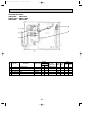
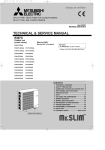
SPLIT-TYPE, HEAT PUMP AIR CONDITIONERS
No. OC238
REVISED EDITION-B
TECHNICAL & SERVICE MANUAL
Series PMH Ceiling Cassettes R407C
Indoor unit
[Model names]
[Service Ref.]
PMH-P1BA
PMH-P1BA1
PMH-P1.6BA
PMH-P1.6BA1
PMH-P2BA
PMH-P2BA1
PMH-P1BA
PMH-P1.6BA
PMH-P2BA
• PMH-P1BA1,PMH-P1.6BA1,PMH-P2BA1
are added in REVISED EDITION-B.
• Please void OC238.REVISED EDITION-A.
• Refer to the OCT03 REVISED EDITION-C as regarding control
relation.This manual does not cover
outdoor units. When servicing them,
please refer to the service manual
No.OC180 REVISED EDITION-A,
OC261 and this manual in a set.
[Service Ref.]
<OC180 REVISED EDITION-A>
PUH-P1.6VGA
PUH-P1.6YGA
PUH-P2VGA
PUH-P2YGA
<OC261>
PUH-P1VGAA.UK
PUH-P1.6VGAA.UK
PUH-P1.6YGAA.UK
PUH-P2VGAA.UK
PUH-P2YGAA.UK
CONTENTS
INDOOR UNIT
FILTER
CENTRALLY CONTROLLED
ON
CHECK MODE
1Hr.
OFF
CLOCK
CHECK
TEST RUN
FILTER
CHECK MODE
TEST RUN
˚C
STAND BY
DEFROST
ERROR CODE
TEMP.
NOT AVAILABLE
FUNCTION
ON/OFF
PMH- P1,1.6,2BA1
PMH- P1,1.6,2BA
REMOTE CONTROLLER
1. TECHNICAL CANGES ········································2
2. COMBINATION OF INDOOR AND OUTDOOR UNITS ···3
3. SAFETY PRECAUTION ······································3
4. PART NAMES AND FUNCTIONS·······················5
5. SPECIFICATIONS ·············································10
6. DATA··································································16
7. OUTLINES AND DIMENSIONS ························29
8. WIRING DIAGRAM···············································30
9. REFRIGERANT SYSTEM DIAGRAM ·····················31
10. TROUBLE SHOOTING ·····································32
11. DISASSEMBLY PROCEDURE··························35
12. PARTS LIST ······················································38
13. OPTIONAL PARTS············································41
OC238A---1.qxp
1
01.10.1 7:48 PM
Page 2
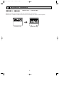
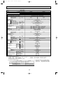
TECHNICAL CHANGES
PMH-P1BA ➔ PMH-P1BA1
PMH-P2BA ➔ PMH-P2BA1
PMH-P1.6BA ➔
PMH-P1.6BA1
● Outdoor units which are connected to PMH-P•BA and PMH-P•BA1 have been added.
● The parts No. of REMOTE CONTROLLER has changed. (The following parts numbers are interchangeable.)
FILTER
CENTRALLY CONTROLLED
ON
CHECK MODE
TEST RUN
➔
1Hr.
OFF
CLOCK
CHECK
FILTER
CHECK MODE
TEST RUN
˚C
STAND BY
DEFROST
ERROR CODE
TEMP.
NOT AVAILABLE
FUNCTION
ON/OFF
[T7W E06 713]
[T7W E00 713]
2
OC238A---1.qxp
01.10.1 7:48 PM
2
Page 3
COMBINATION OF INDOOR AND OUTDOOR UNITS
Outdoor unit
PUH-P
Indoor unit
1.6VGA 1.6YGA 2VGA
PMH-P1BA
PMH-P1.6BA
PMH-P2BA
PMH-P1BA1
PMH-P1.6BA1
PMH-P2BA1
3
2YGA
—
—
—
—
1VGAA.UK 1.6VGAA.UK 1.6YGAA.UK 2VGAA.UK
—
—
—
—
—
—
—
—
—
—
—
—
—
—
—
—
—
—
—
—
—
—
—
—
—
—
—
—
2YGAA.UK
—
—
—
—
—
—
—
—
SAFETY PRECAUTION
Cautions for using with the outdoor unit which adopts R407C refrigerant.
· Do not use the existing refrigerant piping.
-The old refrigerant and lubricant in the existing piping contains a large amount of chlorine which may cause the lubricant of
the new unit to deteriorate.
· Do not use copper pipes which are broken, deformed or discolour .
In addition, be sure that the inner surfaces of the pipes are clean, free of hazardous sulphur and oxides, or have no dust /
dirt, shaving particles, oils, moisture or any other contamination.
-If there is a large amount of residual oil (hydraulic oil, etc.) inside the piping and joints, deterioration of the lubricant will
result.
· Store the piping to be used during installation indoors and keep both ends of the piping sealed until just before
brazing. (Store elbows and other joints in a plastic bag.)
-If dust, dirt, or water enters the refrigerant cycle, deterioration of the oil and compressor trouble may result.
· Use ester oil, ether oil or alkyl benzene (small amount) as the lubricant to coat flares and flange connections.
-The lubricant will degrade if it is mixed with a large amount of mineral oil.
Use liquid refrigerant to fill the system.
-If gas refrigerant is used to fill the system, the composition of the refrigerant in the cylinder will change and performance
may drop.
· Do not use a refrigerant other than R407C.
-If another refrigerant (R22, etc.) is used, the chlorine in the refrigerant may cause the lubricant to deteriorate.
· Use a vacuum pump with a reverse flow check valve.
-The vacuum pump oil may flow back into the refrigerant cycle and cause the lubricant to deteriorate.
· Do not use the following tools that are used with conventional refrigerant.
(Gauge manifold , charge hose, gas leak detector, reverse flow check valve, refrigerant charge base, vacuum gauge,
refrigerant recovery equipment)
-If the conventional refrigerant and lubricant are mixed in the R407C, the refrigerant may deteriorated.
-If water is mixed in the R407C, the lubricant may deteriorate.
-Since R407C does not contain any chlorine, gas leak detectors for conventional refrigerant will not react to it.
· Do not use a charging cylinder.
-Using a charging cylinder may cause the refrigerant to deteriorate.
· Be especially careful when managing the tools.
-if dust, dirt, or water gets in the refrigerant cycle, the refrigerant may deteriorate.
· Do not use the drier which is sold in the field.
-The drier for R407C refrigerant is per-attached to outdoor unit refrigerant circuit.
-Some drier in the field are not in conformity with R407C refrigerant .
3
OC238A---1.qxp
01.10.1 7:48 PM
Page 4
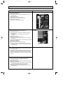
[1] Service tools
Use the below service tools as exclusive tools for R407C refrigerant.
No.
Tool name
Specifications
1
Gauge manifold
·Only for R407C.
·Use the existing fitting SPECIFICATIONS. (UNF7/16)
·Use high-tension side pressure of 3.43MPa·G or over.
2
Charge hose
·Only for R407C.
·Use pressure performance of 5.10MPa·G or over.
3
4
5
6
7
Electronic scale
8
Refrigerant recovery equipment.
Gas leak detector
·Use the detector for R407C.
Adapter for reverse flow check.
·Attach on vacuum pump.
Refrigerant charge base.
Refrigerant cylinder.
·For R407C
·Top of cylinder (Brown)
·Cylinder with syphon
[2] Notice on repair service
·After recovering the all refrigerant in the unit, proceed to working.
·Do not release refrigerant in the air.
·After completing the repair service, recharge the cycle with the specified amount of
liquid refrigerant.
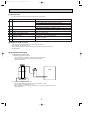
[3] Refrigerant recharging
(1) Refrigerant recharging process
1Direct charging from the cylinder.
·R407C cylinder are available on the market has a syphon pipe.
·Leave the syphon pipe cylinder standing and recharge it.
(By liquid refrigerant)
Unit
Gravimeter
(2) Recharge in refrigerant leakage case
·After recovering the all refrigerant in the unit, proceed to working.
·Do not release the refrigerant in the air.
·After completing the repair service, recharge the cycle with the specified amount of
liquid refrigerant.
4
OC238A---1.qxp
4
01.10.1 7:48 PM
Page 5
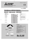
PART NAMES AND FUNCTIONS
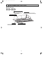
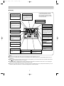
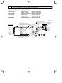
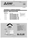
● Indoor (Main) Unit
PMH-P1BA, PMH-P1BA1
PMH-P1.6BA, PMH-P1.6BA1
PMH-P2BA, PMH-P2BA1
Auto Air Swing Vane
Disperses airflow up and
down and adjusts the angle
of airflow direction.
Guide vane
Air flow can be changed to horinzontally
by moving the Guide vane to the left or right.
Horizontal Air Outlet
Filters
Remove dust and pollutants
from inhaled air.
Air intake
Inhales air from room.
5
OC238A---1.qxp
01.10.1 7:48 PM
Page 6
PMH-P1BA
PMH-P1.6BA
PMH-P2BA
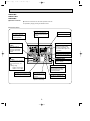
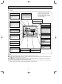
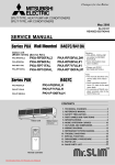
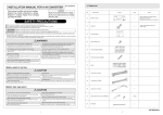
● Remote controller
● Once the controls are set, the same operation mode can
be repeated by simply pressing the ON/OFF button.
● Operation buttons
TIME SETTING button
TIMER button
This switches between
continuous operation and
the timer operation.
This sets of switches the
current time. start time and
stop time.
OPERATION SWITCH
button
AIR SPEED button
This sets the fan speed.
ON/OFF button
This switches between the
operation and stop modes
each time it is pressed. The
lamp on this button lights during operation.
Press this button to
switch the cooler electronic dry (dehumidify)
automatic and heater
modes.
AIR DIRECTION button
This adjusts the vertical angle
of the ventilation.
TEMP. ADJUSTMENT
button
FILTER button
This resets the filter cleaning
indication display.
This sets the room temperature The temperature setting
can be performed in 1°C
units
Setting range
Cooler 19°C to 30°C
Heater 17°C to 28°C
CHECK-TEST RUN button
Only press this button to perform an inspection check or
test operation Do not use it
for normal operation.
TIMER ADJUSTMENT button
LOUVER button
This adjust the current time, start
time and stop time.
This switches the horizontal fan motion ON
and OFF.
(This button does not
operate in this model)
6
VENTILATION button
This sets the ventilation fan
speed.
OC238A---1.qxp
01.10.1 7:48 PM
Page 7
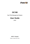
● Display
CENTRALLY
CONTROLLED display
This indicates when the unit is controlled by optional features such as
central control type remote controller.
In this display example on the bottom left, a condition where all display lamps light is shown for explanation purposes although this differs
from actual operation.
CLOCK display
The current time , start time and stop
time can be displayed in ten second
intervals by pressing the time switch
button. The start time or stop time is
always displayed during the timer
operation.
AIR DIRECTION display
TIMER display
This displays the air direction.
This indicates when the continuous
operation and time operation modes
are set.
It also display the time for the timer
operation at the same time as when
it is set.
FAN SPEED display
The selected fan speed is displayed.
ROOM TEMPERATURE display
This indicates the operation mode.
The temperature of the suction air is
displayed during operation. The display range is 8° to 39°C. The display
flashes 8°C when the actual temperature is less than 8° and flashes
39°C when the actual temperature is
greater than 39°C.
STANDBY display
Operation lamp
This indicates when the standby
mode is set from the time the sleep
operation starts until the heating air
is discharged.
This lamp lights during operation,
goes off when the unit stops and
flashes when a malfunction occurs.
OPERATION MODE display
CHECK MODE
TEST RUN
DEFROST display
display
This display lights in the check mode
or when a test operation is performed.
This indicates when the defrost operation is performed.
FILTER display
This lamp lights when the filter need
to be cleaned.
CHECK display
This indicates when a malfunction
has occurred in the unit which should
be checked.
SET TEMPERATURE display
POWER display
This displays the selected setting
temperature.
This lamp lights when electricity is
supplied to the unit.
Caution
● Only the Power display lights when the unit is stopped and power supplied to the unit.
● When power is turned ON for the first time the (CENTRAL CTRL) display appears to go off momentarily but this is not a
malfunction.
● When the central control remote control unit, which is sold separately, is used the ON-OFF button, operation switch button
and
TEMP. adjustment button do not operate.
● “NOT AVAILABLE” is displayed when the Air speed button are pressed.This indicates that this room unit is not equipped
with the fan direction adjustment function and the louver function.
● When power is turned ON for the first time, it is normal that “H0” is displayed on the room temperature indication (For max.
2minutes). Please wait until this “H0” indication disappear then start the operation.
7
OC238A---1.qxp
01.10.1 7:48 PM
Page 8
PMH-P1BA1
PMH-P1.6BA1
PMH-P2BA1
● Remote controller
● Once the controls are set, the same operation mode can
be repeated by simply pressing the ON/OFF button.
● Operation buttons
TEMP. ADJUSTMENT button
This sets the room temperature. The
temperature setting can be performed
in 1: units
Setting range
Cooler 19: to 30:
Heater 17: to 28:
TIME SETTING button
AIR SPEED button
This sets the current time, start time
and stop time.
This sets the ventilation fan speed.
ON/OFF button
This switches between the operation
and stop modes each time it is pressed.
The lamp on this button lights during
operation.
TIMER button
1Hr.
CENTRALLY CONTROLLED
ON
This switches between continuous
operation and the timer operation.
OFF
˚C
CLOCK
CHECK
FILTER
CHECK MODE
TEST RUN
FUNCTION
˚C
STAND BY
DEFROST
ERROR CODE
NOT AVAILABLE
TEMP.
ON/OFF
AIR DIRECTION button
This adjusts the vertical angle of the
ventilation.
FILTER
OPERATION SWITCH button
Press this button to switch the cooler,
electronic dry (dehumidify), automatic
and heater modes.
CHECK TEST
PAR-20MAA
FILTER button
TIMER SET
This resets the filter service indication
display
LOUVER button
VENTILATION button
This switch the horizontal fan motion
ON and OFF.
This sets the ventilation fan speed.
(Not available for this model.)
8
CHECK-TEST RUN button
Only press this button to perform an
inspection check or test operation.
Do not use it for normal operation.
OC238A---1.qxp
01.10.1 7:48 PM
Page 9
● Display
CENTRALLY
CONTROLLED display
This indicates when the unit is controlled by optional features such as
central control type remote
controller.
In this display example on the bottom left, a condition where all display lamps light is shown for explanation purposes although this differs
from actual operation.
CLOCK display
The current time , start time and stop
time can be displayed in ten second
intervals by pressing the time switch
button. The start time or stop time is
always displayed during the timer
operation.
AIR DIRECTION display
TIMER display
This displays the air direction.
This indicates when the continuous
operation and time operation modes
are set.
It also display the time for the timer
operation at the same time as when
it is set.
AIR SPEED display
The selected fan speed is displayed.
ROOM TEMPERATURE
1Hr.
CENTRALLY CONTROLLED
OPERATION MODE display
This indicates the operation mode.
ON
OFF
˚C
CLOCK
CHECK
˚C
STAND BY
DEFROST
ERROR CODE
TEMP.
NOT AVAILABLE
FILTER
CHECK MODE
TEST RUN
FUNCTION
ON/OFF
display
The temperature of the suction air
is displayed during operation. The
display range is 8°C to 39°C. The
display flashes 8°C when the actual
temperature is less than 8°C and
flashes 39°C when the actual temperature is greater than 39°C.
FILTER
STANDBY display
The [STANDBY] symbol is only displayed from the time the heating
operation starts unit the heated air
begins to blow.
CHECK TEST
PAR-20MAA
TIMER SET
Operation lamp
This lamp lights during operation,
goes off when the unit stops and
flashes when a malfunction occurs.
CHECK MODE
TEST RUN
DEFROST display
display
This display lights in the check
mode or when a test operation is
performed.
This indicates when the defrost
operation is performed.
FILTER display
This lamp lights when the filter need
to be cleaned.
CHECK display
This indicates when a malfunction
has occurred in the unit which should
be checked.
SET TEMPERATURE display
POWER display
This displays the selected setting
temperature.
This lamp lights when electricity is
supplied to the unit.
Caution
● Only the Power display lights when the unit is stopped and power supplied to the unit.
● When the central control remote control unit, which is sold separately, is used the ON-OFF button, operation switch button
and
TEMP. adjustment button do not operate.
● “NOT AVAILABLE” is displayed when the Air speed button are pressed.This indicates that this room unit is not equipped
with the fan direction adjustment function and the louver function.
● When power is turned ON for the first time, it is normal that “H0” is displayed on the room temperature indication (For max.
2minutes). Please wait until this “H0” indication disappear then start the operation.
9
OC238A---1.qxp
5
01.10.1 7:48 PM
Page 10
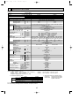
SPECIFICATIONS
5-1. SPECIFICATIONS
Service Ref.
Item
Function
PMH-P1.6BA
Cooling
15,000
4,400
1.65
Btu/h
W
kW
Capacity
Heating
17,100
5,000
1.70
REFRIGERANT PIPING
OUTDOOR UNIT
INDOOR UNIT
Total input
Service Ref.
PMH-P1.6BA
Power supply(phase, cycle, voltage)
Single Phase, 50Hz, 220-230-240V
kW
0.06
Input
0.06
A
Running current
0.29
0.29
A
Starting current
0.32
0.32
External finish
Unit : Galvanized sheets with gray heat insulation, Grille munsell 0.98Y 8.99/0.63
Heat exchanger
Plate fin coil
Fan
Fan(drive) x No.
Lineflow fan (direct) x 1
kW
Fan motor output
0.028
Airflow(Lo - Mi2- Mi1 - Hi) K/min(CFM)
7.0-8.0-9.0-10.0(247-282-318-353)
Pa(mmAq)
External static pressure
0(direct blow)
Operation control & Thermostat
Remote controller & built-in
dB
Noise level(Lo - Mi2 - Mi1 - Hi)
34-36-38-40
mm(in.)
Unit drain pipe I.D.
26(1)
mm(in.)
Dimensions
W
UNIT : 854(33-5/8) PANEL : 1000(39-3/8)
mm(in.)
D
UNIT : 395(15-9/16) PANEL : 470(18-1/2)
mm(in.)
H
UNIT : 230(9-1/16) PANEL : 30(1-3/16)
kg(lbs)
Weight
UNIT : 14(31)
PANEL : 3.0(6.6)
Service Ref.
PUH-P1.6VGA
PUH-P1.6YGA PUH-P1.6VGA
PUH-P1.6YGA
Single Phase, 50Hz, 3 phase, 50Hz, Single Phase, 50Hz, 3 phase, 50Hz,
Power supply (phase, cycle, voltage)
220-230-240V 380-400-415V(4wires) 220-230-240V 380-400-415V(4wires)
7.66
8.19
2.67
2.86
A
Running current
A
Starting current
36
20
External finish
Munsell 5Y 8/1
Refrigerant control
Linear Expansion Valve
Compressor
Hermetic
Model
RE277VHSM
RE277YFKM
kW
Motor output
1.3
Starter type
Line start
Protection devices
w1
w2
W
Crankcase heater
28
Heat exchanger
Plate fin coil
Fan
Fan(drive) x No.
Propeller (direct) x 1
kW
Fan motor output
0.070
K/min(CFM)
Airflow
45(1,590)
Defrost method
Reverse cycle
dB
Noise level
46
Cooling
dB
48
Heating
mm(in.)
Dimensions
900(35-7/16)
W
mm(in.)
330+20(13+3/4)
D
mm(in.)
650(25-5/8)
H
kg(lbs)
55(121)
Weight
R407C
Refrigerant
kg(lbs)
2.6(5.7)
Charge
L
1.2(Ester)MEL56
Oil (Model)
mm(in.)
Liquid
9.52(3/8)
Pipe size O.D.
mm(in.)
Gas
15.88(5/8)
Indoor side
Flared
Connection method
Outdoor side
Flared
Height difference
Max. 40m
Between the indoor &
Piping length
Max. 40m
outdoor unit
Notes1. Rating Conditions (ISO T1)
Cooling····Indoor : D.B. 27˚C(80˚F), W.B. 19˚C (66˚F)
Heating····Indoor : D.B. 20˚C(68˚F)
Refrigerant piping length (one way) : 5m (16ft)
Outdoor
Outdoor
2. Guaranteed operating range
Cooling Upper limit
Lower limit
Upper limit
Heating
Lower limit
Indoor
D.B. 35˚C W.B. 22.5˚C
D.B. 19˚C W.B. 15˚C
D.B. 28˚C
D.B. 17˚C
Outdoor
D.B. 46˚C
D.B. -5˚C
D.B. 24˚C W.B. 18˚C
D.B. -11˚C W.B. -12˚C
w1: Inner thermostat, HP switch, Discharge thermo.
w2: Thermal relay, Discharge thermo, HP switch, Anti-phase protector.
10
: D.B. 35˚C(95˚F), W.B. 24˚C (75˚F)
: D.B. 7˚C(45˚F), W.B. 6˚C (43˚F)
3. Above data based on indicated voltage
Indoor Unit
Single phase 240V 50Hz
Outdoor Unit Single phase 240V 50Hz
3 phase 415V 50Hz
OC238A---1.qxp
01.10.1 7:48 PM
Page 11
Service Ref.
Item
Function
PMH-P2BA
Cooling
18,400
5,400
2.35
Btu/h
W
kW
Capacity
Heating
21,300
6,250
2.42
REFRIGERANT PIPING
OUTDOOR UNIT
INDOOR UNIT
Total input
Service Ref.
PMH-P2BA
Power supply(phase, cycle, voltage)
Single Phase, 50Hz, 220-230-240V
kW
0.06
Input
0.06
A
Running current
0.29
0.29
A
Starting current
0.32
0.32
External finish
Unit : Galvanized sheets with gray heat insulation, Grille munsell 0.98Y 8.99/0.63
Heat exchanger
Plate fin coil
Fan
Fan(drive) x No.
Lineflow fan (direct) x 1
kW
Fan motor output
0.028
Airflow(Lo - Mi2 - Mi1 - Hi) K/min(CFM)
8.0-9.0-10.0-11.0(282-318-353-388)
Pa(mmAq)
External static pressure
0(direct blow)
Operation control & Thermostat
Remote controller & built-in
dB
Noise level(Lo - Mi2 - Mi1 - Hi)
36-38-40-42
mm(in.)
Unit drain pipe I.D.
26(1)
mm(in.)
Dimensions
W
UNIT : 854(33-5/8) PANEL : 1000(39-3/8)
mm(in.)
D
UNIT : 395(15-9/16) PANEL : 470(18-1/2)
mm(in.)
H
UNIT : 230(9-1/16) PANEL : 30(1-3/16)
kg(lbs)
Weight
UNIT : 14(31)
PANEL : 3.0(6.6)
Service Ref.
PUH-P2VGA
PUH-P2YGA
PUH-P2VGA
PUH-P2YGA
Single Phase, 50Hz, 3 phase, 50Hz, Single Phase, 50Hz, 3 phase, 50Hz,
Power supply (phase, cycle, voltage)
220-230-240V 380-400-415V(4wires) 220-230-240V 380-400-415V(4wires)
11.11
11.51
3.88
4.02
A
Running current
A
Starting current
74
30
External finish
Munsell 5Y 8/1
Refrigerant control
Linear Expansion Valve
Compressor
Hermetic
Model
NE38VMJM
NE38YEJM
kW
Motor output
1.7
Starter type
Line start
Protection devices
w1
w2
W
Crankcase heater
35
Heat exchanger
Plate fin coil
Fan
Fan(drive) x No.
Propeller (direct) x 1
kW
Fan motor output
0.070
K/min(CFM)
Airflow
55(1,940)
Defrost method
Reverse cycle
dB
Noise level
48
Cooling
dB
49
Heating
mm(in.)
Dimensions
900(35-7/16)
W
mm(in.)
330+20(13+3/4)
D
mm(in.)
855(33-5/8)
H
kg(lbs)
71(157)
Weight
R407C
Refrigerant
kg(lbs)
3.1(6.8)
Charge
L
1.2(Ester)MEL56
Oil (Model)
mm(in.)
Liquid
9.52(3/8)
Pipe size O.D.
mm(in.)
Gas
15.88(5/8)
Indoor side
Flared
Connection method
Outdoor side
Flared
Height difference
Max. 40m
Between the indoor &
Piping length
Max. 40m
outdoor unit
Notes1. Rating Conditions (ISO T1)
Cooling····Indoor : D.B. 27˚C(80˚F), W.B. 19˚C (66˚F)
Heating····Indoor : D.B. 20˚C(68˚F)
Refrigerant piping length (one way) : 5m (16ft)
Outdoor
Outdoor
2. Guaranteed operating range
Cooling Upper limit
Lower limit
Upper limit
Heating
Lower limit
Indoor
D.B. 35˚C W.B. 22.5˚C
D.B. 19˚C W.B. 15˚C
D.B. 28˚C
D.B. 17˚C
Outdoor
D.B. 46˚C
D.B. -5˚C
D.B. 24˚C W.B. 18˚C
D.B. -11˚C W.B. -12˚C
w1: Inner thermostat, HP switch, Discharge thermo.
w2: Thermal relay, Discharge thermo, HP switch, Anti-phase protector.
11
: D.B. 35˚C(95˚F), W.B. 24˚C (75˚F)
: D.B. 7˚C(45˚F), W.B. 6˚C (43˚F)
3. Above data based on indicated voltage
Indoor Unit
Single phase 240V 50Hz
Outdoor Unit Single phase 240V 50Hz
3 phase 415V 50Hz
OC238A---1.qxp
01.10.1 7:48 PM
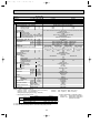
Page 12
Service Ref.
Item
Function
PMH-P1BA / PMH-P1BA1
Cooling
10,700
3,150
1.15
Btu/h
W
kW
Capacity
Heating
11,600
3,400
1.06
REFRIGERANT PIPING
OUTDOOR UNIT
INDOOR UNIT
Total input
Service Ref.
PMH-P1BA / PMH-P1BA1
Power supply(phase, cycle, voltage)
Single Phase, 50Hz, 220-230-240V
kW
0.04
Input
0.04
A
Running current
0.19
0.19
A
Starting current
0.21
0.21
External finish
Unit : Galvanized sheets with gray heat insulation, Grille munsell 0.98Y 8.99/0.63
Heat exchanger
Plate fin coil
Fan
Fan(drive) x No.
Lineflow fan (direct) x 1
kW
Fan motor output
0.028
Airflow(Lo - Mi2 - Mi1 - Hi) K/min(CFM)
6.3-6.8-7.6-8.4(222-240-268-297)
Pa(mmAq)
External static pressure
0(direct blow)
Operation control & Thermostat
Remote controller & built-in
dB
Noise level(Lo - Mi2 - Mi1 - Hi)
29-31-33-35
mm(in.)
Unit drain pipe I.D.
26(1)
mm(in.)
Dimensions
W
UNIT : 854(33-5/8) PANEL : 1000(39-3/8)
mm(in.)
D
UNIT : 395(15-9/16) PANEL : 470(18-1/2)
mm(in.)
H
UNIT : 230(9-1/16) PANEL : 30(1-3/16)
kg(lbs)
Weight
UNIT : 14(31)
PANEL : 3.0(6.6)
Service Ref.
PUH-P1VGAA.UK
Power supply (phase, cycle, voltage)
Single Phase, 50Hz,
220-230-240V
A
Running current
4.92
4.52
A
Starting current
30
External finish
Munsell 5Y 7/1
Refrigerant control
Linear Expansion Valve
Compressor
Hermetic
Model
RE189VHSMT
kW
Motor output
0.85
Starter type
Line start
Protection devices
Inner thermostat, HP switch, Discharge thermo.
W
Crankcase heater
30
Heat exchanger
Plate fin coil
Fan
Fan(drive) x No.
Propeller (direct) x 1
kW
Fan motor output
0.070
K/min(CFM)
Airflow
45(1,590)
Defrost method
Reverse cycle
dB
Noise level
46
Cooling
dB
48
Heating
mm(in.)
Dimensions
900(35-7/16)
W
mm(in.)
330+20(13+3/4)
D
mm(in.)
650(25-5/8)
H
kg(lbs)
Weight
50(110)
Refrigerant
R407C
kg(lbs)
Charge
1.7(3.7)
L
Oil (Model)
0.57(Ester)MEL56
mm(in.)
Liquid
Pipe size O.D.
6.35(1/4)
mm(in.)
Gas
12.7(1/2)
Indoor side
Connection method
Flared
Outdoor side
Flared
Height difference
Between the indoor &
Max. 30m
Piping length
outdoor unit
Max. 30m
Notes1. Rating Conditions (ISO T1)
Cooling····Indoor : D.B. 27˚C(80˚F), W.B. 19˚C (66˚F)
Heating····Indoor : D.B. 20˚C(68˚F)
Refrigerant piping length (one way) : 5m (16ft)
Outdoor
Outdoor
2. Guaranteed operating range
Cooling Upper limit
Lower limit
Upper limit
Heating
Lower limit
Indoor
D.B. 35˚C W.B. 22.5˚C
D.B. 19˚C W.B. 15˚C
D.B. 28˚C
D.B. 17˚C
Outdoor
D.B. 46˚C
D.B. -5˚C
D.B. 24˚C W.B. 18˚C
D.B. -11˚C W.B. -12˚C
12
: D.B. 35˚C(95˚F), W.B. 24˚C (75˚F)
: D.B. 7˚C(45˚F), W.B. 6˚C (43˚F)
3. Above data based on indicated voltage
Indoor Unit
Single phase 240V 50Hz
Outdoor Unit Single phase 240V 50Hz
OC238A---1.qxp
01.10.1 7:48 PM
Page 13
Service Ref.
Item
Function
PMH-P1.6BA / PMH-P1.6BA1
Cooling
Heating
15,000
17,100
Capacity
4,400
5,000
1.65
Total input
1.70
Service Ref.
PMH-P1.6BA / PMH-P1.6BA1
Power supply(phase, cycle, voltage)
Single Phase, 50Hz, 220-230-240V
kW
0.06
Input
0.06
A
Running current
0.29
0.29
A
Starting current
0.32
0.32
External finish
Unit : Galvanized sheets with gray heat insulation, Grille munsell 0.98Y 8.99/0.63
Heat exchanger
Plate fin coil
Fan
Fan(drive) x No.
Lineflow fan (direct) x 1
kW
Fan motor output
0.028
Airflow(Lo - Mi2- Mi1 - Hi) K/min(CFM)
7.0-8.0-9.0-10.0(247-282-318-353)
Pa(mmAq)
External static pressure
0(direct blow)
Operation control & Thermostat
Remote controller & built-in
dB
Noise level(Lo - Mi2 - Mi1 - Hi)
34-36-38-40
mm(in.)
Unit drain pipe I.D.
26(1)
mm(in.)
Dimensions
W
UNIT : 854(33-5/8) PANEL : 1000(39-3/8)
mm(in.)
D
UNIT : 395(15-9/16) PANEL : 470(18-1/2)
mm(in.)
H
UNIT : 230(9-1/16) PANEL : 30(1-3/16)
kg(lbs)
Weight
UNIT : 14(31)
PANEL : 3.0(6.6)
Service Ref.
PUH-P1.6VGAA.UK PUH-P1.6YGAA.UK PUH-P1.6VGAA.UK PUH-P1.6YGAA.UK
Single Phase, 50Hz, 3 phase, 50Hz, Single Phase, 50Hz, 3 phase, 50Hz,
Power supply (phase, cycle, voltage)
220-230-240V 380-400-415V(4wires) 220-230-240V 380-400-415V(4wires)
7.36
7.59
2.49
2.56
A
Running current
A
Starting current
36
20
External finish
Munsell 5Y 7/1
Refrigerant control
Linear Expansion Valve
Compressor
Hermetic
Model
RE277VHSMT
RE277YFKM
kW
Motor output
1.3
Starter type
Line start
Protection devices
w1
w2
W
Crankcase heater
30
Heat exchanger
Plate fin coil
Fan
Fan(drive) x No.
Propeller (direct) x 1
kW
Fan motor output
0.070
K/min(CFM)
Airflow
45(1,590)
Defrost method
Reverse cycle
dB
Noise level
47
Cooling
dB
49
Heating
mm(in.)
Dimensions
900(35-7/16)
W
mm(in.)
330+20(13+3/4)
D
mm(in.)
650(25-5/8)
H
kg(lbs)
54(119)
Weight
R407C
Refrigerant
kg(lbs)
2.5(5.5)
Charge
L
0.57(Ester)MEL56
Oil (Model)
mm(in.)
9.52(3/8)
Liquid
Pipe size O.D.
mm(in.)
15.88(5/8)
Gas
Indoor side
Flared
Connection method
Outdoor side
Flared
Height difference
Max. 40m
Between the indoor &
Piping length
Max. 40m
outdoor unit
REFRIGERANT PIPING
OUTDOOR UNIT
INDOOR UNIT
Btu/h
W
kW
Notes1. Rating Conditions (ISO T1)
Cooling····Indoor : D.B. 27˚C(80˚F), W.B. 19˚C (66˚F)
Heating····Indoor : D.B. 20˚C(68˚F)
Refrigerant piping length (one way) : 5m (16ft)
Outdoor
Outdoor
2. Guaranteed operating range
Cooling Upper limit
Lower limit
Upper limit
Heating
Lower limit
Indoor
D.B. 35˚C W.B. 22.5˚C
D.B. 19˚C W.B. 15˚C
D.B. 28˚C
D.B. 17˚C
Outdoor
D.B. 46˚C
D.B. -5˚C
D.B. 24˚C W.B. 18˚C
D.B. -11˚C W.B. -12˚C
w1: Inner thermostat, HP switch, Discharge thermo.
w2: Thermal relay, Discharge thermo, HP switch, Anti-phase protector.
13
: D.B. 35˚C(95˚F), W.B. 24˚C (75˚F)
: D.B. 7˚C(45˚F), W.B. 6˚C (43˚F)
3. Above data based on indicated voltage
Indoor Unit
Single phase 240V 50Hz
Outdoor Unit Single phase 240V 50Hz
3 phase 415V 50Hz
OC238A---1.qxp
01.10.1 7:48 PM
Page 14
Service Ref.
Item
Function
PMH-P2BA / PMH-P2BA1
Cooling
18,400
5,400
2.35
Btu/h
W
kW
Capacity
Heating
21,450
6,250
2.42
REFRIGERANT PIPING
OUTDOOR UNIT
INDOOR UNIT
Total input
Service Ref.
PMH-P2BA / PMH-P2BA1
Power supply(phase, cycle, voltage)
SinglePhase, 50Hz, 220-230-240V
kW
0.06
Input
0.06
A
Running current
0.29
0.29
A
Starting current
0.32
0.32
External finish
Unit : Galvanized sheets with gray heat insulation, Grille munsell 0.98Y 8.99/0.63
Heat exchanger
Plate fin coil
Fan
Fan(drive) x No.
Lineflow fan (direct) x 1
kW
Fan motor output
0.028
Airflow(Lo - Mi2 - Mi1 - Hi) K/min(CFM)
8.0-9.0-10.0-11.0(282-318-353-388)
Pa(mmAq)
External static pressure
0(direct blow)
Operation control & Thermostat
Remote controller & built-in
dB
Noise level(Lo - Mi2 - Mi1 - Hi)
36-38-40-42
mm(in.)
Unit drain pipe I.D.
26(1)
mm(in.)
Dimensions
W
UNIT : 854(33-5/8) PANEL : 1000(39-3/8)
mm(in.)
D
UNIT : 395(15-9/16) PANEL : 470(18-1/2)
mm(in.)
H
UNIT : 230(9-1/16) PANEL : 30(1-3/16)
kg(lbs)
Weight
UNIT : 14(31)
PANEL : 3.0(6.6)
Service Ref.
PUH-P2VGAA.UK PUH-P2YGAA.UK PUH-P2VGAA.UK PUH-P2YGAA.UK
Single Phase, 50Hz, 3 phase, 50Hz, Single Phase, 50Hz, 3 phase, 50Hz,
Power supply (phase, cycle, voltage)
220-230-240V 380-400-415V(4wires) 220-230-240V 380-400-415V(4wires)
10.26
10.57
3.70
3.82
A
Running current
A
Starting current
62
31
External finish
Munsell 5Y 7/1
Refrigerant control
Linear Expansion Valve
Compressor
Hermetic
Model
NE36VMJMT
NE38YEJM
kW
Motor output
1.6
Starter type
Line start
Protection devices
w1
w2
W
Crankcase heater
38
Heat exchanger
Plate fin coil
Fan
Fan(drive) x No.
Propeller (direct) x 1
kW
Fan motor output
0.070
K/min(CFM)
Airflow
55(1,940)
Defrost method
Reverse cycle
dB
Noise level
48
Cooling
dB
50
Heating
mm(in.)
Dimensions
900(35-7/16)
W
mm(in.)
330+20(13+3/4)
D
mm(in.)
855(33-5/8)
H
kg(lbs)
74(163)
Weight
R407C
Refrigerant
kg(lbs)
2.6(5.7)
Charge
L
1.2(Ester)MEL56
Oil (Model)
mm(in.)
9.52(3/8)
Liquid
Pipe size O.D.
mm(in.)
15.88(5/8)
Gas
Indoor side
Flared
Connection method
Outdoor side
Flared
Height difference
Max. 40m
Between the indoor &
Piping length
Max. 40m
outdoor unit
Notes1. Rating Conditions (ISO T1)
Cooling····Indoor : D.B. 27˚C(80˚F), W.B. 19˚C (66˚F)
Heating····Indoor : D.B. 20˚C(68˚F)
Refrigerant piping length (one way) : 5m (16ft)
Outdoor
Outdoor
2. Guaranteed operating range
Cooling Upper limit
Lower limit
Upper limit
Heating
Lower limit
Indoor
D.B. 35˚C W.B. 22.5˚C
D.B. 19˚C W.B. 15˚C
D.B. 28˚C
D.B. 17˚C
Outdoor
D.B. 46˚C
D.B. -5˚C
D.B. 24˚C W.B. 18˚C
D.B. -11˚C W.B. -12˚C
w1: Inner thermostat, HP switch, Discharge thermo.
w2: Thermal relay, Discharge thermo, HP switch, Anti-phase protector.
14
: D.B. 35˚C(95˚F), W.B. 24˚C (75˚F)
: D.B. 7˚C(45˚F), W.B. 6˚C (43˚F)
3. Above data based on indicated voltage
Indoor Unit
Single phase 240V 50Hz
Outdoor Unit Single phase 240V 50Hz
3 phase 415V 50Hz
OC238A---1.qxp
01.10.1 7:48 PM
Page 15
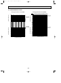
5-2. Air capacity taken from outside
PMH-P·BA series are possible to be taken air from outside.
When taking air from the outside, the duct fan can be used to.
The air capacity should be 20% or less of the air flow SPEC(Hi).
250
288.5
904-{2.8
108
{100
22
{1
Flesh air intake hole
(Knock out)
Flesh air intake hole
(Knock out)
Air flow
(Hi)
PMH-P1BA,
Air capacity taken outside
3
PMH-P1BA1
3
8.4m /min
1.6m /min
3
PMH-P1.6BA, PMH-P1.6BA1
10.0m /min
PMH-P2BA,
11.0m /min
3
2.0m /min
3
PMH-P2BA1
3
2.2m /min
How to read curves
Duct characteristics
at site
Curve in the
left praphs.
3
Q…Planned amount of fresh air intake <m /min>
A…Static pressure loss of fresh air intake duct system with air flow amount Q <Pa>
B
A
0
C
1
Q
B…Forced static pressure at air conditioner inlet with air flow amount Q <Pa>
C…Static pressure of booster fan with air flow amount Q <Pa>
C
A
D…Static pressure loss increase amount of fresh air intake duct system for air flow amount Q <Pa>
E
2
E…Static pressure of indoor unit with air flow amount Q <Pa>
Q
3
Qa…Estimated amount of fresh air intake without D <m /min>
A
D
3
Characteristic diagram of air capacity taken from outside
Q
Qa
Static pressure (Pa)
50.0
0.0
2 intakes
1 intake
-50.0
-100.0
0.0
0.5
1.0
1.5
Air flow (m3/min)
15
2.0
2.5
OC238A---1.qxp
6
01.10.1 7:48 PM
Page 16
DATA
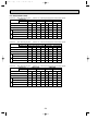
6-1. PERFORMANCE DATA
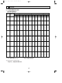
1) COOLING CAPACITY(1)
PMH-P1BA, PMH-P1BA1
Indoor
Indoor
Intake air Intake air
D.B.(°C) W.B.(°C)
CA
20
SHC(W) SHF
P.C.
Outdoor intake air D.B.(°C)
25
CA SHC(W) SHF
P.C.
CA
30
SHC(W) SHF
P.C.
20
16
3,119
2,089
0.67
0.92
3,024
2,026
0.67
0.97
2,930
1,963
0.67
1.03
20
18
3,339
1,836
0.55
0.94
3,245
1,784
0.55
0.99
3,134
1,724
0.55
1.06
20
20
3,591
1,544
0.43
0.97
3,512
1,510
0.43
1.01
3,418
1,470
0.43
1.08
22
16
3,119
2,339
0.75
0.92
3,024
2,268
0.75
0.97
2,930
2,197
0.75
1.03
22
18
3,339
2,104
0.63
0.94
3,245
2,044
0.63
0.99
3,134
1,975
0.63
1.06
22
20
3,591
1,831
0.51
0.97
3,512
1,791
0.51
1.01
3,418
1,743
0.51
1.08
24
16
3,119
2,588
0.83
0.92
3,024
2,510
0.83
0.97
2,930
2,431
0.83
1.03
24
18
3,339
2,371
0.71
0.94
3,245
2,304
0.71
0.99
3,134
2,225
0.71
1.06
24
20
3,591
2,119
0.59
0.97
3,512
2,072
0.59
1.01
3,418
2,016
0.59
1.08
24
22
3,827
1,799
0.47
0.99
3,749
1,762
0.47
1.05
3,654
1,717
0.47
1.12
26
16
3,119
2,838
0.91
0.92
3,024
2,752
0.91
0.97
2,930
2,666
0.91
1.03
26
18
3,339
2,638
0.79
0.94
3,245
2,563
0.79
0.99
3,134
2,476
0.79
1.06
26
20
3,591
2,406
0.67
0.97
3,512
2,353
0.67
1.01
3,418
2,290
0.67
1.08
26
22
3,827
2,105
0.55
0.99
3,749
2,062
0.55
1.05
3,654
2,010
0.55
1.12
28
16
3,119
3,087
0.99
0.92
3,024
2,994
0.99
0.97
2,930
2,900
0.99
1.03
28
18
3,339
2,905
0.87
0.94
3,245
2,823
0.87
0.99
3,134
2,727
0.87
1.06
28
20
3,591
2,693
0.75
0.97
3,512
2,634
0.75
1.01
3,418
2,563
0.75
1.08
28
22
3,827
2,411
0.63
0.99
3,749
2,362
0.63
1.05
3,654
2,302
0.63
1.12
30
16
3,119
3,119
1.00
0.92
3,024
3,024
1.00
0.97
2,930
2,930
1.00
1.03
30
18
3,339
3,172
0.95
0.94
3,245
3,082
0.95
0.99
3,134
2,978
0.95
1.06
30
20
3,591
2,981
0.83
0.97
3,512
2,915
0.83
1.01
3,418
2,837
0.83
1.08
30
22
3,827
2,717
0.71
0.99
3,749
2,661
0.71
1.05
3,654
2,594
0.71
1.12
32
16
3,119
3,119
1.00
0.92
3,024
3,024
1.00
0.97
2,930
2,930
1.00
1.03
32
18
3,339
3,339
1.00
0.94
3,245
3,245
1.00
0.99
3,134
3,134
1.00
1.06
32
20
3,591
3,268
0.91
0.97
3,512
3,196
0.91
1.01
3,418
3,110
0.91
1.08
32
22
3,827
3,024
0.79
0.99
3,749
2,961
0.79
1.05
3,654
2,887
0.79
1.12
34
16
3,119
3,119
1.00
0.92
3,024
3,024
1.00
0.97
2,930
2,930
1.00
1.03
34
18
3,339
3,339
1.00
0.94
3,245
3,245
1.00
0.99
3,134
3,134
1.00
1.06
34
20
3,591
3,555
0.99
0.97
3,512
3,477
0.99
1.01
3,418
3,384
0.99
1.08
34
22
3,827
3,330
0.87
0.99
3,749
3,261
0.87
1.05
3,654
3,179
0.87
1.12
Note CA : Capacity (W)
P.C. : Power consumption (kW)
SHC(W) : Sensible heat capacity
SHF : Sensible heat factor
Above data based on indicated voltage
Indoor unit
: Single phase 240V 50Hz
Outdoor unit : Single phase 240V 50Hz
16
OC238A---1.qxp
01.10.1 7:48 PM
Page 17
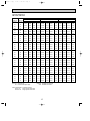
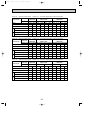
COOLING CAPACITY(2)
PMH-P1BA, PMH-P1BA1
Indoor
Indoor
Intake air Intake air
D.B.(°C) W.B.(°C)
CA
35
SHC(W) SHF
P.C.
Outdoor intake air D.B.(°C)
40
CA SHC(W) SHF
P.C.
CA
45
SHC(W) SHF
P.C.
20
16
2,804
1,878
0.67
1.10
2,678
1,794
0.67
1.18
2,552
1,710
0.67
1.28
20
18
3,024
1,663
0.55
1.13
2,930
1,611
0.55
1.22
2,741
1,507
0.55
1.31
20
20
3,276
1,409
0.43
1.16
3,150
1,355
0.43
1.24
2,961
1,273
0.43
1.33
22
16
2,804
2,103
0.75
1.10
2,678
2,008
0.75
1.18
2,552
1,914
0.75
1.28
22
18
3,024
1,905
0.63
1.13
2,930
1,846
0.63
1.22
2,741
1,727
0.63
1.31
22
20
3,276
1,671
0.51
1.16
3,150
1,607
0.51
1.24
2,961
1,510
0.51
1.33
24
16
2,804
2,327
0.83
1.10
2,678
2,222
0.83
1.18
2,552
2,118
0.83
1.28
24
18
3,024
2,147
0.71
1.13
2,930
2,080
0.71
1.22
2,741
1,946
0.71
1.31
24
20
3,276
1,933
0.59
1.16
3,150
1,859
0.59
1.24
2,961
1,747
0.59
1.33
24
22
3,528
1,658
0.47
1.18
3,402
1,599
0.47
1.28
3,213
1,510
0.47
1.36
26
16
2,804
2,551
0.91
1.10
2,678
2,437
0.91
1.18
2,552
2,322
0.91
1.28
26
18
3,024
2,389
0.79
1.13
2,930
2,314
0.79
1.22
2,741
2,165
0.79
1.31
26
20
3,276
2,195
0.67
1.16
3,150
2,111
0.67
1.24
2,961
1,984
0.67
1.33
26
22
3,528
1,940
0.55
1.18
3,402
1,871
0.55
1.28
3,213
1,767
0.55
1.36
28
16
2,804
2,775
0.99
1.10
2,678
2,651
0.99
1.18
2,552
2,526
0.99
1.28
28
18
3,024
2,631
0.87
1.13
2,930
2,549
0.87
1.22
2,741
2,384
0.87
1.31
28
20
3,276
2,457
0.75
1.16
3,150
2,363
0.75
1.24
2,961
2,221
0.75
1.33
28
22
3,528
2,223
0.63
1.18
3,402
2,143
0.63
1.28
3,213
2,024
0.63
1.36
30
16
2,804
2,804
1.00
1.10
2,678
2,678
1.00
1.18
2,552
2,552
1.00
1.28
30
18
3,024
2,837
0.95
1.13
2,930
2,783
0.95
1.22
2,741
2,603
0.95
1.31
30
20
3,276
2,719
0.83
1.16
3,150
2,615
0.83
1.24
2,961
2,458
0.83
1.33
30
22
3,528
2,505
0.71
1.18
3,402
2,415
0.71
1.28
3,213
2,281
0.71
1.36
32
16
2,804
2,804
1.00
1.10
2,678
2,678
1.00
1.18
2,552
2,552
1.00
1.28
32
18
3,024
3,024
1.00
1.13
2,930
2,930
1.00
1.22
2,741
2,741
1.00
1.31
32
20
3,276
2,981
0.91
1.16
3,150
2,867
0.91
1.24
2,961
2,695
0.91
1.33
32
22
3,528
2,787
0.79
1.18
3,402
2,688
0.79
1.28
3,213
2,538
0.79
1.36
34
16
2,804
2,804
1.00
1.10
2,678
2,678
1.00
1.18
2,552
2,552
1.00
1.28
34
18
3,024
3,024
1.00
1.13
2,930
2,930
1.00
1.22
2,741
2,741
1.00
1.31
34
20
3,276
3,243
0.99
1.16
3,150
3,119
0.99
1.24
2,961
2,931
0.99
1.33
34
22
3,528
3,069
0.87
1.18
3,402
2,960
0.87
1.28
3,213
2,795
0.87
1.36
Note CA : Capacity (W)
P.C. : Power consumption (kW)
SHC(W) : Sensible heat capacity
SHF : Sensible heat factor
Above data based on indicated voltage
Indoor unit
: Single phase 240V 50Hz
Outdoor unit : Single phase 240V 50Hz
17
OC238A---1.qxp
01.10.1 7:48 PM
Page 18
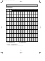
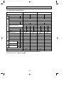
COOLING CAPACITY(3)
PMH-P1.6BA, PMH-P1.6BA1
Indoor
Indoor
Intake air Intake air
D.B.(°C) W.B.(°C)
CA
20
SHC(W) SHF
P.C.
Outdoor intake air D.B.(°C)
25
CA SHC(W) SHF
P.C.
CA
30
SHC(W) SHF
P.C.
20
16
4,356
2,614
0.60
1.32
4,224
2,534
0.60
1.39
4,092
2,455
0.60
1.48
20
18
4,664
2,239
0.48
1.34
4,532
2,175
0.48
1.42
4,378
2,101
0.48
1.52
20
20
5,016
1,806
0.36
1.39
4,906
1,766
0.36
1.45
4,774
1,719
0.36
1.55
22
16
4,356
2,962
0.68
1.32
4,224
2,872
0.68
1.39
4,092
2,783
0.68
1.48
22
18
4,664
2,612
0.56
1.34
4,532
2,538
0.56
1.42
4,378
2,452
0.56
1.52
22
20
5,016
2,207
0.44
1.39
4,906
2,159
0.44
1.45
4,774
2,101
0.44
1.55
24
16
4,356
3,311
0.76
1.32
4,224
3,210
0.76
1.39
4,092
3,110
0.76
1.48
24
18
4,664
2,985
0.64
1.34
4,532
2,900
0.64
1.42
4,378
2,802
0.64
1.52
24
20
5,016
2,608
0.52
1.39
4,906
2,551
0.52
1.45
4,774
2,482
0.52
1.55
24
22
5,346
2,138
0.40
1.42
5,236
2,094
0.40
1.50
5,104
2,042
0.40
1.60
26
16
4,356
3,659
0.84
1.32
4,224
3,548
0.84
1.39
4,092
3,437
0.84
1.48
26
18
4,664
3,358
0.72
1.34
4,532
3,263
0.72
1.42
4,378
3,152
0.72
1.52
26
20
5,016
3,010
0.60
1.39
4,906
2,944
0.60
1.45
4,774
2,864
0.60
1.55
26
22
5,346
2,566
0.48
1.42
5,236
2,513
0.48
1.50
5,104
2,450
0.48
1.60
28
16
4,356
4,008
0.92
1.32
4,224
3,886
0.92
1.39
4,092
3,765
0.92
1.48
28
18
4,664
3,731
0.80
1.34
4,532
3,626
0.80
1.42
4,378
3,502
0.80
1.52
28
20
5,016
3,411
0.68
1.39
4,906
3,336
0.68
1.45
4,774
3,246
0.68
1.55
28
22
5,346
2,994
0.56
1.42
5,236
2,932
0.56
1.50
5,104
2,858
0.56
1.60
30
16
4,356
4,356
1.00
1.32
4,224
4,224
1.00
1.39
4,092
4,092
1.00
1.48
30
18
4,664
4,104
0.88
1.34
4,532
3,988
0.88
1.42
4,378
3,853
0.88
1.52
30
20
5,016
3,812
0.76
1.39
4,906
3,729
0.76
1.45
4,774
3,628
0.76
1.55
30
22
5,346
3,421
0.64
1.42
5,236
3,351
0.64
1.50
5,104
3,267
0.64
1.60
32
16
4,356
4,356
1.00
1.32
4,224
4,224
1.00
1.39
4,092
4,092
1.00
1.48
32
18
4,664
4,477
0.96
1.34
4,532
4,351
0.96
1.42
4,378
4,203
0.96
1.52
32
20
5,016
4,213
0.84
1.39
4,906
4,121
0.84
1.45
4,774
4,010
0.84
1.55
32
22
5,346
3,849
0.72
1.42
5,236
3,770
0.72
1.50
5,104
3,675
0.72
1.60
34
16
4,356
4,356
1.00
1.32
4,224
4,224
1.00
1.39
4,092
4,092
1.00
1.48
34
18
4,664
4,664
1.00
1.34
4,532
4,532
1.00
1.42
4,378
4,378
1.00
1.52
34
20
5,016
4,615
0.92
1.39
4,906
4,514
0.92
1.45
4,774
4,392
0.92
1.55
34
22
5,346
4,277
0.80
1.42
5,236
4,189
0.80
1.50
5,104
4,083
0.80
1.60
Note CA : Capacity (W)
P.C. : Power consumption (kW)
SHC(W) : Sensible heat capacity
SHF : Sensible heat factor
Above data based on indicated voltage
Indoor unit
: Single phase 240V 50Hz
Outdoor unit : Single phase 240V 50Hz / 3 phase 415V 50Hz
18
OC238A---1.qxp
01.10.1 7:48 PM
Page 19
COOLING CAPACITY(4)
PMH-P1.6BA, PMH-P1.6BA1
Indoor
Indoor
Intake air Intake air
D.B.(°C) W.B.(°C)
CA
35
SHC(W) SHF
P.C.
Outdoor intake air D.B.(°C)
40
CA SHC(W) SHF
P.C.
CA
45
SHC(W) SHF
P.C.
20
16
3,916
2,350
0.60
1.58
3,740
2,244
0.60
1.70
3,564
2,138
0.60
1.84
20
18
4,224
2,028
0.48
1.63
4,092
1,964
0.48
1.75
3,828
1,837
0.48
1.88
20
20
4,576
1,647
0.36
1.67
4,400
1,584
0.36
1.78
4,136
1,489
0.36
1.91
22
16
3,916
2,663
0.68
1.58
3,740
2,543
0.68
1.70
3,564
2,424
0.68
1.84
22
18
4,224
2,365
0.56
1.63
4,092
2,292
0.56
1.75
3,828
2,144
0.56
1.88
22
20
4,576
2,013
0.44
1.67
4,400
1,936
0.44
1.78
4,136
1,820
0.44
1.91
24
16
3,916
2,976
0.76
1.58
3,740
2,842
0.76
1.70
3,564
2,709
0.76
1.84
24
18
4,224
2,703
0.64
1.63
4,092
2,619
0.64
1.75
3,828
2,450
0.64
1.88
24
20
4,576
2,380
0.52
1.67
4,400
2,288
0.52
1.78
4,136
2,151
0.52
1.91
24
22
4,928
1,971
0.40
1.70
4,752
1,901
0.40
1.83
4,488
1,795
0.40
1.95
26
16
3,916
3,289
0.84
1.58
3,740
3,142
0.84
1.70
3,564
2,994
0.84
1.84
26
18
4,224
3,041
0.72
1.63
4,092
2,946
0.72
1.75
3,828
2,756
0.72
1.88
26
20
4,576
2,746
0.60
1.67
4,400
2,640
0.60
1.78
4,136
2,482
0.60
1.91
26
22
4,928
2,365
0.48
1.70
4,752
2,281
0.48
1.83
4,488
2,154
0.48
1.95
28
16
3,916
3,603
0.92
1.58
3,740
3,441
0.92
1.70
3,564
3,279
0.92
1.84
28
18
4,224
3,379
0.80
1.63
4,092
3,274
0.80
1.75
3,828
3,062
0.80
1.88
28
20
4,576
3,112
0.68
1.67
4,400
2,992
0.68
1.78
4,136
2,812
0.68
1.91
28
22
4,928
2,760
0.56
1.70
4,752
2,661
0.56
1.83
4,488
2,513
0.56
1.95
30
16
3,916
3,916
1.00
1.58
3,740
3,740
1.00
1.70
3,564
3,564
1.00
1.84
30
18
4,224
3,717
0.88
1.63
4,092
3,601
0.88
1.75
3,828
3,369
0.88
1.88
30
20
4,576
3,478
0.76
1.67
4,400
3,344
0.76
1.78
4,136
3,143
0.76
1.91
30
22
4,928
3,154
0.64
1.70
4,752
3,041
0.64
1.83
4,488
2,872
0.64
1.95
32
16
3,916
3,916
1.00
1.58
3,740
3,740
1.00
1.70
3,564
3,564
1.00
1.84
32
18
4,224
4,055
0.96
1.63
4,092
3,928
0.96
1.75
3,828
3,675
0.96
1.88
32
20
4,576
3,844
0.84
1.67
4,400
3,696
0.84
1.78
4,136
3,474
0.84
1.91
32
22
4,928
3,548
0.72
1.70
4,752
3,421
0.72
1.83
4,488
3,231
0.72
1.95
34
16
3,916
3,916
1.00
1.58
3,740
3,740
1.00
1.70
3,564
3,564
1.00
1.84
34
18
4,224
4,224
1.00
1.63
4,092
4,092
1.00
1.75
3,828
3,828
1.00
1.88
34
20
4,576
4,210
0.92
1.67
4,400
4,048
0.92
1.78
4,136
3,805
0.92
1.91
34
22
4,928
3,942
0.80
1.70
4,752
3,802
0.80
1.83
4,488
3,590
0.80
1.95
Note CA : Capacity (W)
P.C. : Power consumption (kW)
SHC(W) : Sensible heat capacity
SHF : Sensible heat factor
Above data based on indicated voltage
Indoor unit
: Single phase 240V 50Hz
Outdoor unit : Single phase 240V 50Hz
19
OC238A---1.qxp
01.10.1 7:48 PM
Page 20
COOLING CAPACITY(5)
PMH-P2BA, PMH-P2BA1
Indoor
Indoor
Intake air Intake air
D.B.(°C) W.B.(°C)
CA
20
SHC(W) SHF
P.C.
Outdoor intake air D.B.(°C)
25
CA SHC(W) SHF
P.C.
CA
30
SHC(W) SHF
P.C.
20
16
5,346
3,047
0.57
1.88
5,184
2,955
0.57
1.99
5,022
2,863
0.57
2.10
20
18
5,724
2,576
0.45
1.92
5,562
2,503
0.45
2.02
5,373
2,418
0.45
2.16
20
20
6,156
2,031
0.33
1.97
6,021
1,987
0.33
2.07
5,859
1,933
0.33
2.21
22
16
5,346
3,475
0.65
1.88
5,184
3,370
0.65
1.99
5,022
3,264
0.65
2.10
22
18
5,724
3,034
0.53
1.92
5,562
2,948
0.53
2.02
5,373
2,848
0.53
2.16
22
20
6,156
2,524
0.41
1.97
6,021
2,469
0.41
2.07
5,859
2,402
0.41
2.21
24
16
5,346
3,903
0.73
1.88
5,184
3,784
0.73
1.99
5,022
3,666
0.73
2.10
24
18
5,724
3,492
0.61
1.92
5,562
3,393
0.61
2.02
5,373
3,278
0.61
2.16
24
20
6,156
3,016
0.49
1.97
6,021
2,950
0.49
2.07
5,859
2,871
0.49
2.21
24
22
6,561
2,428
0.37
2.02
6,426
2,378
0.37
2.14
6,264
2,318
0.37
2.28
26
16
5,346
4,330
0.81
1.88
5,184
4,199
0.81
1.99
5,022
4,068
0.81
2.10
26
18
5,724
3,950
0.69
1.92
5,562
3,838
0.69
2.02
5,373
3,707
0.69
2.16
26
20
6,156
3,509
0.57
1.97
6,021
3,432
0.57
2.07
5,859
3,340
0.57
2.21
26
22
6,561
2,952
0.45
2.02
6,426
2,892
0.45
2.14
6,264
2,819
0.45
2.28
28
16
5,346
4,758
0.89
1.88
5,184
4,614
0.89
1.99
5,022
4,470
0.89
2.10
28
18
5,724
4,407
0.77
1.92
5,562
4,283
0.77
2.02
5,373
4,137
0.77
2.16
28
20
6,156
4,001
0.65
1.97
6,021
3,914
0.65
2.07
5,859
3,808
0.65
2.21
28
22
6,561
3,477
0.53
2.02
6,426
3,406
0.53
2.14
6,264
3,320
0.53
2.28
30
16
5,346
5,186
0.97
1.88
5,184
5,028
0.97
1.99
5,022
4,871
0.97
2.10
30
18
5,724
4,865
0.85
1.92
5,562
4,728
0.85
2.02
5,373
4,567
0.85
2.16
30
20
6,156
4,494
0.73
1.97
6,021
4,395
0.73
2.07
5,859
4,277
0.73
2.21
30
22
6,561
4,002
0.61
2.02
6,426
3,920
0.61
2.14
6,264
3,821
0.61
2.28
32
16
5,346
5,346
1.00
1.88
5,184
5,184
1.00
1.99
5,022
5,022
1.00
2.10
32
18
5,724
5,323
0.93
1.92
5,562
5,173
0.93
2.02
5,373
4,997
0.93
2.16
32
20
6,156
4,986
0.81
1.97
6,021
4,877
0.81
2.07
5,859
4,746
0.81
2.21
32
22
6,561
4,527
0.69
2.02
6,426
4,434
0.69
2.14
6,264
4,322
0.69
2.28
34
16
5,346
5,346
1.00
1.88
5,184
5,184
1.00
1.99
5,022
5,022
1.00
2.10
34
18
5,724
5,724
1.00
1.92
5,562
5,562
1.00
2.02
5,373
5,373
1.00
2.16
34
20
6,156
5,479
0.89
1.97
6,021
5,359
0.89
2.07
5,859
5,215
0.89
2.21
34
22
6,561
5,052
0.77
2.02
6,426
4,948
0.77
2.14
6,264
4,823
0.77
2.28
Note CA : Capacity (W)
P.C. : Power consumption (kW)
SHC(W) : Sensible heat capacity
SHF : Sensible heat factor
Above data based on indicated voltage
Indoor unit
: Single phase 240V 50Hz
Outdoor unit : Single phase 240V 50Hz / 3 phase 415V 50Hz
20
OC238A---1.qxp
01.10.1 7:48 PM
Page 21
COOLING CAPACITY(6)
PMH-P2BA, PMH-P2BA1
Indoor
Indoor
Intake air Intake air
D.B.(°C) W.B.(°C)
CA
35
SHC(W) SHF
P.C.
Outdoor intake air D.B.(°C)
40
CA SHC(W) SHF
P.C.
CA
45
SHC(W) SHF
P.C.
20
16
4,806
2,739
0.57
2.26
4,590
2,616
0.57
2.42
4,374
2,493
0.57
2.62
20
18
5,184
2,333
0.45
2.31
5,022
2,260
0.45
2.49
4,698
2,114
0.45
2.68
20
20
5,616
1,853
0.33
2.37
5,400
1,782
0.33
2.54
5,076
1,675
0.33
2.73
22
16
4,806
3,124
0.65
2.26
4,590
2,984
0.65
2.42
4,374
2,843
0.65
2.62
22
18
5,184
2,748
0.53
2.31
5,022
2,662
0.53
2.49
4,698
2,490
0.53
2.68
22
20
5,616
2,303
0.41
2.37
5,400
2,214
0.41
2.54
5,076
2,081
0.41
2.73
24
16
4,806
3,508
0.73
2.26
4,590
3,351
0.73
2.42
4,374
3,193
0.73
2.62
24
18
5,184
3,162
0.61
2.31
5,022
3,063
0.61
2.49
4,698
2,866
0.61
2.68
24
20
5,616
2,752
0.49
2.37
5,400
2,646
0.49
2.54
5,076
2,487
0.49
2.73
24
22
6,048
2,238
0.37
2.42
5,832
2,158
0.37
2.61
5,508
2,038
0.37
2.77
26
16
4,806
3,893
0.81
2.26
4,590
3,718
0.81
2.42
4,374
3,543
0.81
2.62
26
18
5,184
3,577
0.69
2.31
5,022
3,465
0.69
2.49
4,698
3,242
0.69
2.68
26
20
5,616
3,201
0.57
2.37
5,400
3,078
0.57
2.54
5,076
2,893
0.57
2.73
26
22
6,048
2,722
0.45
2.42
5,832
2,624
0.45
2.61
5,508
2,479
0.45
2.77
28
16
4,806
4,277
0.89
2.26
4,590
4,085
0.89
2.42
4,374
3,893
0.89
2.62
28
18
5,184
3,992
0.77
2.31
5,022
3,867
0.77
2.49
4,698
3,617
0.77
2.68
28
20
5,616
3,650
0.65
2.37
5,400
3,510
0.65
2.54
5,076
3,299
0.65
2.73
28
22
6,048
3,205
0.53
2.42
5,832
3,091
0.53
2.61
5,508
2,919
0.53
2.77
30
16
4,806
4,662
0.97
2.26
4,590
4,452
0.97
2.42
4,374
4,243
0.97
2.62
30
18
5,184
4,406
0.85
2.31
5,022
4,269
0.85
2.49
4,698
3,993
0.85
2.68
30
20
5,616
4,100
0.73
2.37
5,400
3,942
0.73
2.54
5,076
3,705
0.73
2.73
30
22
6,048
3,689
0.61
2.42
5,832
3,558
0.61
2.61
5,508
3,360
0.61
2.77
32
16
4,806
4,806
1.00
2.26
4,590
4,590
1.00
2.42
4,374
4,374
1.00
2.62
32
18
5,184
4,821
0.93
2.31
5,022
4,670
0.93
2.49
4,698
4,369
0.93
2.68
32
20
5,616
4,549
0.81
2.37
5,400
4,374
0.81
2.54
5,076
4,112
0.81
2.73
32
22
6,048
4,173
0.69
2.42
5,832
4,024
0.69
2.61
5,508
3,801
0.69
2.77
34
16
4,806
4,806
1.00
2.26
4,590
4,590
1.00
2.42
4,374
4,374
1.00
2.62
34
18
5,184
5,184
1.00
2.31
5,022
5,022
1.00
2.49
4,698
4,698
1.00
2.68
34
20
5,616
4,998
0.89
2.37
5,400
4,806
0.89
2.54
5,076
4,518
0.89
2.73
34
22
6,048
4,657
0.77
2.42
5,832
4,491
0.77
2.61
5,508
4,241
0.77
2.77
Note CA : Capacity (W)
P.C. : Power consumption (kW)
SHC(W) : Sensible heat capacity
SHF : Sensible heat factor
Above data based on indicated voltage
Indoor unit
: Single phase 240V 50Hz
Outdoor unit : Single phase 240V 50Hz / 3 phase 415V 50Hz
21
OC238A---1.qxp
01.10.1 7:48 PM
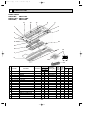
Page 22
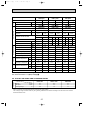
2) HEATING CAPACITY
Indoor
intake
air
D.B.(°C)
Service Ref.
PMH-P1BA
PMH-P1BA1
PMH-P1.6BA
PMH-P1.6BA1
PMH-P2BA
PMH-P2BA1
Outdoor intake air W.B.(°C)
-10
CA
-5
P.C.
CA
0
P.C.
CA
5
P.C.
CA
10
P.C.
CA
15
P.C.
CA
P.C.
15
2,159 0.63 2,346 0.69 2,618 0.80 3,434 0.95 3,876 1.06 4,318 1.14
20
2,074 0.68 2,244 0.74 2,482 0.86 3,315 1.03 3,740 1.14 4,165 1.23
25
2,006 0.72 2,176 0.81 2,380 0.93 3,128 1.09 3,604 1.22 4,012 1.32
15
3,175 1.00 3,450 1.11 3,850 1.28 5,050 1.53 5,700 1.70 6,350 1.84
20
3,050 1.09 3,300 1.19 3,650 1.38 4,875 1.65 5,500 1.84 6,125 1.97
25
2,950 1.16 3,200 1.29 3,500 1.50 4,600 1.75 5,300 1.96 5,900 2.12
15
3,969 1.43 4,313 1.57 4,813 1.82 6,313 2.18 7,125 2.42 7,938 2.61
20
3,813 1.55 4,125 1.69 4,563 1.96 6,094 2.35 6,875 2.61 7,656 2.81
25
3,688 1.65 4,000 1.84 4,375 2.13 5,750 2.49 6,625 2.80 7,375 3.01
Note CA : Capacity (W)
P.C. : Power consumption (kW)
Above data based on indicated voltage
Indoor unit
: Single phase 240V 50Hz
Outdoor unit : Single phase 240V 50Hz / 3 phase 415V 50Hz
Cooling capacity correction factors
Service Ref.
PMH-P1BA
PMH-P1BA1
PMH-P1.6BA
PMH-P1.6BA1
PMH-P2BA
PMH-P2BA1
Refrigerant piping length (one way)
20m
25m
30m
35m
5m
10m
15m
1.00
0.993
0.984
0.978
0.969
0.961
1.00
0.993
0.984
0.978
0.969
1.00
0.993
0.984
0.978
0.969
40m
45m
50m
—
—
—
—
0.961
0.956
0.948
—
—
0.961
0.956
0.948
—
—
Refrigerant piping length (one way)
20m
25m
30m
35m
40m
45m
50m
Heating capacity correction factors
Service Ref.
PMH-P1BA
PMH-P1BA1
PMH-P1.6BA
PMH-P1.6BA1
PMH-P2BA
PMH-P2BA1
5m
10m
15m
1.00
0.998
0.995
0.993
0.990
0.988
—
—
—
—
1.00
0.998
0.995
0.993
0.990
0.988
0.985
0.983
—
—
1.00
0.998
0.995
0.993
0.990
0.988
0.985
0.983
—
—
22
OC238A---1.qxp
01.10.1 7:48 PM
Page 23
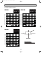
6-2. PERFORMANCE CURVE
Cooling performance curve(50Hz)
Heating performance curve(50Hz)
Correcting the capacity line influenced by frosting
Not correcting the capactiy line influenced by frosting
1.4
INDOOR
W.B.(°C)
1.2
22
1.0
20
18
16
0.8
CAPACITY (RATIO)
CAPACITY (RATIO)
1.4
1.2
15
20
25
INDOOR
D.B.(°C)
25
20
INDOOR
D.B.(°C)
1.0
0.8
0.6
0.4
22
20
18
16
TOTAL INPUT (RATIO)
1.2
INDOOR
W.B.(°C)
1.0
0.8
0.6
0
10
20
30
40
1.2
15
1.0
0.8
0.6
0.4
-12 -10
0.4
-5
TOTAL INPUT (RATIO)
1.4
46
-5
0
5
10
OUTDOOR W.B.(°C)
OUTDOOR D.B.(°C)
23
15
OC238A---1.qxp
01.10.1 7:48 PM
Page 24
6-3. ELECTRICAL DATA
Indoor unit … 220V 50Hz Single phase
Indoor unit
PMH-P1.6BA
PMH-P2BA
Outdoor unit PUH-P1.6VGA PUH-P1.6YGA PUH-P2VGA
PUH-P2YGA
Mode
Cool
Heat
Heat
Cool
Heat
Capacity (W)
4,300
4,900 4,300 4,900
5,300
6,150 5,300 6,150
Total Input (kW)
1.54
1.58
1.54
1.58
2.27
2.32
2.27
2.32
Outdoor unit Indoor unit
Service Ref.
Outdoor unit…220V 50Hz Single phase / 380V 50Hz 3phase
Input (kW)
0.06
0.06
0.06
0.06
0.06
0.06
0.06
0.06
Current (A)
0.29
0.29
0.29
0.29
0.29
0.29
0.29
0.29
33
33
18
18
68
68
28
28
7.54
7.96
2.75
2.90
11.13
11.50
4.01
4.14
Starting current (A)
Current (A)
Indoor unit … 230V 50Hz Single phase
Indoor unit
Cool
Heat
Outdoor unit…230V 50Hz Single phase / 400V 50Hz 3phase
PMH-P1.6BA
PMH-P2BA
Outdoor unit PUH-P1.6VGA PUH-P1.6YGA PUH-P2VGA
PUH-P2YGA
Mode
Cool
Heat
Capacity (W)
4,350
4,950 4,350 4,950
5,350 6,200
5,350 6,200
Total Input (kW)
1.59
1.64
1.59
1.64
2.31
2.37
2.31
2.37
Outdoor unit Indoor unit
Service Ref.
Cool
Input (kW)
0.06
0.06
0.06
0.06
0.06
0.06
0.06
0.06
Current (A)
0.29
0.29
0.29
0.29
0.29
0.29
0.29
0.29
35
35
19
19
71
71
29
29
7.64
8.05
2.71
2.85
3.91
4.06
Starting current (A)
Current (A)
Indoor unit … 240V 50Hz Single phase
Indoor unit
Heat
Cool
Heat
11.05 11.45
Cool
Heat
Outdoor unit…240V 50Hz Single phase / 415V 50Hz 3phase
PMH-P1.6BA
PMH-P2BA
Outdoor unit PUH-P1.6VGA PUH-P1.6YGA PUH-P2VGA
PUH-P2YGA
Mode
Cool
Heat
Capacity (W)
4,400
5,000 4,400 5,000
5,400 6,250
Total Input (kW)
1.65
1.70
1.65
1.70
2.35
2.42
2.35
2.42
Outdoor unit Indoor unit
Service Ref.
Cool
Input (kW)
0.06
0.06
0.06
0.06
0.06
0.06
0.06
0.06
Current (A)
0.29
0.29
0.29
0.29
0.29
0.29
0.29
0.29
36
36
20
20
74
74
30
30
7.66
8.19
2.67
2.86
3.88
4.02
Starting current (A)
Current (A)
Cool
Heat
Cool
Heat
11.11 11.51
24
Cool
Heat
5.400 6,250
OC238A---1.qxp
01.10.1 7:48 PM
Page 25
Indoor unit ··· 220V 50Hz Single phase
Service Ref.
Indoor unit
Outdoor unit ··· 220V 50Hz Single phase / 380V 50Hz 3phase
PMH-P1BA
PMH-P1BA1
PMH-P1.6BA
PMH-P1.6BA1
PMH-P2BA
PMH-P2BA1
Mode
Cool
Capacity (W)
3,050 3,300 4,300
Total Input (kW)
1.13
1.04
1.54
Outdoor unit Indoor unit
Outdoor unit PUH-P1VGAA.UK PUH-P1.6VGAA.UK PUH-P1.6YGAA.UK PUH-P2VGAA.UK PUH-P2YGAA.UK
Input (kW)
0.04
0.04
Current (A)
0.19
Starting current (A)
Current (A)
Service Ref.
Cool
Cool
Heat
4,900 4,300 4,900
5,300
6,150 5,300 6,150
1.58
1.54
1.58
2.27
2.32
2.27
2.32
0.06
0.06
0.06
0.06
0.06
0.06
0.06
0.06
0.19
0.29
0.29
0.29
0.29
0.29
0.29
0.29
0.29
27
27
33
33
18
18
62
62
31
31
5.37
4.93
8.03
8.28
2.71
2.80
11.19
11.53
4.05
4.17
Indoor unit ··· 230V 50Hz Single phase
Indoor unit
Cool
Heat
Heat
Heat
Cool
Heat
Outdoor unit ··· 230V 50Hz Single phase / 400V 50Hz 3phase
PMH-P1BA
PMH-P1BA1
PMH-P1.6BA
PMH-P1.6BA1
PMH-P2BA
PMH-P2BA1
Mode
Cool
Capacity (W)
3,100 3,350 4,350
Total Input (kW)
1.14
1.05
Outdoor unit Indoor unit
Outdoor unit PUH-P1VGAA.UK PUH-P1.6VGAA.UK PUH-P1.6YGAA.UK PUH-P2VGAA.UK PUH-P2YGAA.UK
Input (kW)
0.04
Current (A)
Starting current (A)
Current (A)
Service Ref.
Cool
Heat
Cool
Heat
Cool
Heat
Cool
Heat
4,950 4,350 4,950
5,350 6,200
5,350 6,200
1.59
1.64
1.59
1.64
2.31
2.37
2.31
2.37
0.04
0.06
0.06
0.06
0.06
0.06
0.06
0.06
0.06
0.19
0.19
0.29
0.29
0.29
0.29
0.29
0.29
0.29
0.29
29
29
35
35
19
19
62
62
31
31
5.13
4.72
7.68
7.92
2.58
2.66
3.84
3.96
Indoor unit ··· 240V 50Hz Single phase
Indoor unit
Heat
10.71 11.03
Outdoor unit ··· 240V 50Hz Single phase / 415V 50Hz 3phase
PMH-P1BA
PMH-P1BA1
PMH-P1.6BA
PMH-P1.6BA1
PMH-P2BA
PMH-P2BA1
Mode
Cool
Capacity (W)
3,150 3,400 4,400 5,000 4,400 5,000
Total Input (kW)
1.15
1.06
1.65
1.70
1.65
Outdoor unit Indoor unit
Outdoor unit PUH-P1VGAA.UK PUH-P1.6VGAA.UK PUH-P1.6YGAA.UK PUH-P2VGAA.UK PUH-P2YGAA.UK
Input (kW)
0.04
0.04
0.06
0.06
Current (A)
0.19
0.19
0.29
30
30
4.92
4.52
Starting current (A)
Current (A)
Heat
Cool
Heat
Cool
Heat
Cool
Heat
Cool
Heat
5,400 6,250
5.400 6,250
1.70
2.35
2.42
2.35
2.42
0.06
0.06
0.06
0.06
0.06
0.06
0.29
0.29
0.29
0.29
0.29
0.29
0.29
36
36
20
20
62
62
31
31
7.36
7.59
2.49
2.56
3.70
3.82
25
10.26 10.57
OC238A---1.qxp
01.10.1 7:48 PM
Page 26
6-4. STANDARD OPERATION DATA
Service Ref.
PMH-P1.6BA
Total
Mode
Cooling
Heating
Cooling
Heating
Capacity
W
4,400
5,000
5,400
6,250
Input
kW
1.65
1.70
2.35
2.42
Indoor unit Service Ref.
PMH-P1.6BA
PMH-P2BA
1, 50
1, 50
240
240
Electrical circuit
Phase, Hz
Volts
V
Amperes
A
Volts
Amperes
Discharge pressure
Refrigerant circuit
0.29
0.29
0.29
0.29
PUH-P • GA
Outdoor unit Service Ref.
PUH-P • GA
1.6V
1.6Y
1.6V
1.6Y
2V
2Y
2V
2Y
1, 50
3, 50
1, 50
3, 50
1, 50
3, 50
1, 50
3, 50
V
240
415
240
415
240
415
240
415
A
MPa
7.66
2.67
8.19
2.86
11.11
3.88
11.51
Phase, Hz
Outdoor Indoor side
side
PMH-P2BA
1.99
2.15
2.37
4.02
2.52
(kgf/F)
(20.3)
(21.9)
(24.2)
MPa
0.49
(5.0)
0.41
(4.2)
0.49
(5.0)
(4.2)
Discharge temperature
°C
75
80
86
93
Condensing temperature
°C
46
50
53
53
Suction temperature
°C
5.0
1.2
5.0
1.0
Ref. pipe length
m
5
5
5
5
D.B.
°C
27
20
27
20
W.B.
°C
19
15
19
15
D.B.
°C
12.4
47.2
11.4
49.0
D.B.
°C
35
7
35
7
W.B.
°C
24
6
24
6
SHF
0.70
—
0.67
—
BF
0.15
—
0.15
—
Suction pressure
(kgf/F)
Intake air temperature
Discharge air temperature
Intake air temperature
The unit of pressure has been changed to Mpa based on international SI system.
f)
The conversion factor is : 1(Mpa)=10.2(kgf/f
26
(25.7)
0.41
OC238A---1.qxp
01.10.1 7:48 PM
Page 27
PMH-P1BA
PMH-P1BA1
Service Ref.
Total
Mode
Cooling
Heating
Cooling
Heating
Cooling
Heating
W
3,150
3,400
4,400
5,000
5,400
6,250
Input
kW
1.15
1.06
1.65
1.70
2.35
2.42
PMH-P1BA
PMH-P1BA1
PMH-P1.6BA
PMH-P1.6BA1
PMH-P2BA
PMH-P2BA1
1, 50
1, 50
1, 50
240
240
240
Electrical circuit
Phase, Hz
Volts
V
Amperes
A
Discharge pressure
0.19
0.29
0.29
PUH-P • GAA.UK
1V
1V
1, 50
1, 50
V
240
240
240
A
MPa
4.92
2.01
4.52
1.85
7.36 2.49
1.99
Volts
Amperes
0.19
PUH-P • GAA.UK
Outdoor unit Service Ref.
Phase, Hz
Refrigerant circuit
PMH-P2BA
PMH-P2BA1
Capacity
Indoor unit Service Ref.
Outdoor Indoor side
side
PMH-P1.6BA
PMH-P1.6BA1
1.6V 1.6Y 1.6V 1.6Y
0.29
0.29
PUH-P • GAA.UK
2V
2Y
2V
2Y
1, 50 3, 50 1, 50 3, 50 1, 50 3, 50 1, 50 3, 50
415
240
415
240
415
240
415
7.59 2.56 10.26 3.70 10.57 3.82
2.52
2.15
2.37
(kgf/F)
(20.5)
(18.9)
MPa
0.55
(5.6)
0.44
(4.2)
0.49
(5.0)
(4.2)
(5.0)
(4.2)
Discharge temperature
°C
71
70
75
80
86
93
Condensing temperature
°C
48
44
46
50
53
53
Suction temperature
°C
8.0
4.0
5.0
1.2
5.0
1.0
Ref. pipe length
m
5
5
5
5
5
5
D.B.
°C
27
20
27
20
27
20
W.B.
°C
19
15
19
15
19
15
D.B.
°C
13.3
41.5
12.4
47.2
11.4
49.0
D.B.
°C
35
7
35
7
35
7
W.B.
°C
24
6
24
6
24
6
SHF
0.77
—
0.70
—
0.67
—
BF
0.09
—
0.15
—
0.15
—
Suction pressure
(kgf/F)
Intake air temperature
Discharge air temperature
Intake air temperature
(20.3)
(21.9)
(24.2)
0.41
0.49
(25.7)
0.41
The unit of pressure has been changed to Mpa based on international SI system.
f)
The conversion factor is : 1(Mpa)=10.2(kgf/f
Standard
6-5. OUTLET AIR SPEED AND COVERAGE RANGE
Air flow
Air speed
Coverage range
m3/min
m/sec.
m
PMH-P1BA
PMH-P1BA1
8.4
3.7
5.9
PMH-P1.6BA
PMH-P1.6BA1
10.0
4.3
7.0
PMH-P2BA
PMH-P2BA1
11.0
4.7
7.7
w The air coverage range is the value up to the position where the air speed is 0.25m/sec.
When air is blown out horizontally from the unit at the Hi notch position.
The coverage range should be used only as a general guideline since it varies according to the size of the room and the
furniture inside the room.
27
OC238A---1.qxp
01.10.1 7:48 PM
Page 28
6-6. NOISE CRITERION CURVES
PMH-P1BA
PMH-P1BA1
NOTCH SPL(dB)
Hi
35
33
Mi1
31
Mi2
Lo
29
LINE
PMH-P1.6BA
PMH-P1.6BA1
LINE
90
80
70
NC-70
60
NC-60
50
NC-50
40
NC-40
30
NC-30
20
APPROXIMATE THRESHOLD OF
HEARING FOR CONTINUOUS
NOISE
NC-20
OCTAVE BAND SOUND PRESSURE LEVEL, dB re 0.002 MICRO BAR
90
OCTAVE BAND SOUND PRESSURE LEVEL, dB re 0.002 MICRO BAR
NOTCH SPL(dB)
Hi
40
38
Mi1
36
Mi2
Lo
34
80
70
NC-70
60
NC-60
50
NC-50
40
NC-40
30
NC-30
20
APPROXIMATE
THRESHOLD OF
HEARING FOR
CONTINUOUS
NOISE
NC-20
10
10
63
125
250
500
1000
2000
4000
63
8000
PMH-P2BA
PMH-P2BA1
125
250
500
1000
2000
4000
8000
BAND CENTER FREQUENCIES, Hz
BAND CENTER FREQUENCIES, Hz
NOTCH SPL(dB)
Hi
42
40
Mi1
38
Mi2
Lo
36
LINE
UNIT
CEILING
OCTAVE BAND SOUND PRESSURE LEVEL, dB re 0.002 MICRO BAR
90
80
70
1.5m
NC-70
60
NC-60
MICROPHONE
50
NC-50
40
Ambient temperature 27:
NC-40
Test conditions are based on JIS Z8731
30
NC-30
20
APPROXIMATE
THRESHOLD OF
HEARING FOR
CONTINUOUS
NOISE
NC-20
10
63
125
250
500
1000
2000
4000
8000
BAND CENTER FREQUENCIES, Hz
28
Refrigerant
pipe(liquid)
outer side of grille
(96)
45
340 suspension bolt pitch
43
46
Lower view
200
200
Panel(grille):PMP-40BM
600
812
759
drain pan
{50
Air outlet(lower)
1000 outer side of grille
Front
(56)
Drainage pipe
PVC pipe:VP-20[O.D.{25]
seiling opening
430
470
395
302
254
141
ceiling
drain pan
panel
same line
Left side
ceiling panel
176
Refrigerant pipe(gas)
96
20
20
198
(10)
17.5
17.5
20
74.5
26
40
28
28
outer line of grille
53
30
elect box
center of unit
20
20
74.5
26
247
69
Top
470 outer side of grille
45
230
(20)
29
60
O.D.{35
O.D.{6.35(1/4") O.D.{9.52(3/8")
O.D.{12.7(1/2") O.D.{15.88(5/8")
PVC pipe:VP-20[O.D.{25(1")]
Knock out
Installation space required around indoor unit
Panel(grille):PMP-40BM
suspension bolt(M10 or W3/8)
PMH-P1.6/P2BA
PMH-P1.6/P2BA1
250
90-
Flesh air intake hole
288.5
{100
4-{2.8 Burring hole
Details of fresh air intake hole
pipe cover
Liquid pipe
Gas pipe
Terminal biock for remoto controller
Right side
Terminal block for
indoor/outdoor connection
Drainage piping
Refrigerant
piping
PMH-P1BA
PMH-P1BA1
2
110
2
{1
230
1000 outer side of grille
960 seiling opening
811 suspension bolt pitch
759
20
235 or more
mounting plate
01.10.1 7:48 PM
110
7
108
OC238A---1.qxp
Page 29
OUTLINES AND DIMENSIONS
PMH-P1BA, PMH-P1BA1
PMH-P1.6BA, PMH-P1.6BA1
PMH-P2BA, PMH-P2BA1
Unit : mm
OC238A---1.qxp
8
01.10.1 7:48 PM
Page 30
WIRING DIAGRAM
PMH-P1BA, PMH-P1.6BA, PMH-P2BA
PMH-P1BA1, PMH-P1.6BA1, PMH-P2BA1
[LEGEND]
DP
DS
MF
MV
TB4
TB5
TH1
NOTES:
1.Since the outdoor side electric wiring may change be sure to check
the outdoor unit electric wiring for servicing.
2.Indoor and outdoor connecting wires are made with polarities, make
wiring matching terminal numbers(S1, S2, S3).
3.Symbols used in wiring diagram above are,
:Connector, :Terminal (block).
NAME
INDOOR CONTROLLER BOARD
CONNECTOR (LOSSNAY)
CONNECTOR (REMOTE SWITCH)
CONNECTOR (HA TERMINAL-A)
FUSE (6.3A, 250V)
POWER SUPPLY (I.B)
POWER SUPPLY (R.B)
TRANSMISSION (INDOOR-OUTDOOR)
JUMPER WIRE (MODEL SELECTION)
JUMPER WIRE (CAPACITY CODE)
SWITCH (EMERGENCY OPERATION)
TRANSFORMER
RELAY (DRAIN PUMP)
VARISTOR
REMOTE CONTROLLER BOARD
CONNECTOR (PROGRAM TIMER)
TERMINAL BLOCK
(REMOTE CONTROLLER TRAMSMISSION LINE)
DRAIN-UP MACHINE
DRAIN SENSOR
FAN MOTOR
VANE MOTOR
TERMINAL BLOCK
(INDOOR/OUTDOOR CONNECTING LINE)
Please set the voltage using the remote controller.
For the setting method, please refer to the indoor unit Installation Manual.
<w1>
PIPE TEMPERATURE THERMISTOR/LIQUID
(0°C/15K", 25°C/5.4K" DETECT)
TH5
CONDENSER/EVAPORATOR TEMPERATURE
THERMISTOR (0°C/15K", 25°C/5.4K" DETECT)
Service board
J11 J12 J13 J14 J15
J11 J12 J13 J14 J15
1 2 3 4
PMH-P1BA
PMH-P1BA1
ON
OFF
J21 J22 J23 J24
1 2 3 4
SW2 PMH-P1.6BA
PMH-P1.6BA1
ON
OFF
J21 J22 J23 J24
1 2 3 4
PMH-P2BA
PMH-P2BA1
ON
OFF
J21 J22 J23 J24
OUTDOOR UNIT
S1
S2
S3
TB4
S1
S2
S3
<PUH-P1.6, 2VGA>
<PUH-P1, 1.6, 2VGAA.UK>
POWER SUPPLY
~(1PHASE)
220 - 230 - 240V 50Hz
L
N
TB1
TERMINAL BLOCK
(REMOTE CONTROL TRANSMISSION LINE)
ROOM TEMPERATURE THERMISTOR
(0°C/15K", 25°C/5.4K" DETECT)
TH2
Manufacture
MODELS
PMH-P1/1.6/2BA
SW1
PMH-P1/1.6/2BA1
S1
S2
S3
<PUH-P1.6, 2YGA>
<PUH-P1.6, 2YGAA.UK>
POWER SUPPLY
3N~(3PHASE 4WIRES)
380 - 400 - 415V 50Hz
L1
L2
L3
N
TB1
R.B
TB5
MF
BLU
BLU
SYMBOL
I.B
CN2L
CN32
CN41
FUSE
LED1
LED2
LED3
SW1
SW2
SWE
T
X1
ZNR
R.B
CN2
TB6
5
I.B
2
1 TRANSMISSION WIRES DC12V
2 1
LED1
CN90
CN32
REMOTE
CONTROLLER
CN22
(BLU)
6 5 4 3 2 1
FAN
(WHT)
LED2
BRN
ORN
YLW
BLU
BLU
3
2
1
INTAKE
CN20
(RED)
2
1
LIQUID
CN21
(WHT)
5
3
1
POWER FUSE
CN03
(RED)
DP
D.SENSOR
CN31
(WHT)
ZNR
1
3
D.U.M
CNP
(YLW)
2
1
PIPE
CN29
(BLK)
2
1
VANE
CN6V
(WHT)
6
5
4
3
2
1
CN2
1 2
TB6
BLK
BLK
DS
BLK
BLK
TH1
BLK
BLK
TH2
BLK
BLK
TH5
BRN
RED
ORN
YLW
GRN
1
2
3 MV
4
5
T
X1
X1
LED3
CN41
CN2L
ON
SW1
J24
J23
J22
J21
J15
J14
J13
J12
J11
OFF
SWE
SW2
30
See fig : w1
OC238A---2.qxp
01.10.1 7:49 PM
9
Page 31
REFRIGERANT SYSTEM DIAGRAM
PMH-P1BA, PMH-P1BA1 / PUH-P1VGAA.UK
PMH-P1.6BA
/ PUH-P1.6VGA ,
PUH-P1.6YGA ,
PMH-P1.6BA1
/ PUH-P1.6VGAA.UK
PMH-P2BA
/ PUH-P2VGA ,
PUH-P2YGA ,
PMH-P2BA1
/ PUH-P2VGAA.UK ,
PUH-P1.6VGAA.UK ,
PUH-P1.6YGAA.UK
, PUH-P1.6YGAA.UK
PUH-P2VGAA.UK ,
PUH-P2YGAA.UK
PUH-P2YGAA.UK
Unit : mm
Indoor unit
Refrigerant pipe
12.7mm([1/2"):PMH-P1BA/PMH-P1BA1
15.88mm([5/8"):PMH-P1.6,2BA/PMH-P1.6,2BA1 4-way valve
(with heat insulator)
Ball valve
Strainer
Thermistor
(TH1)
Thermistor
(TH5)
Distributor
with
strainer
Thermistor
(TH2)
Flexible tube
Service
port
Strainer
Flared
connection
Refrigerant flow in cooling
Refrigerant flow in heating
<4-way valve solenoid coil>
Heating ON
Cooling OFF
High pressure Outdoor unit
switch
Thermistor
(TH6)
Service
port
Muffler
Thermistor
(TH4)
Accumulator
Drier
Ball valve
Refrigerant pipe
6.35mm([1/4"):PMH-P1BA/PMH-P1BA1 (with service port)
9.52mm([3/8"):PMH-P1.6,2BA/PMH-P1.6,2BA1
(with heat insulator)
31
Compressor
Strainer
Strainer
Linear expansion valve
Thermistor
(TH3)
Distributor
with
strainer
OC238A---2.qxp
10
01.10.1 7:49 PM
Page 32
TROUBLE SHOOTING
How to check the parts PMH-P1BA, PMH-P1.6BA, PMH-P2BA
PMH-P1BA1, PMH-P1.6BA1, PMH-P2BA1
Parts name
Check points
Room temperature
thermistor
(TH1)
Pipe temperature
thermistor
(TH2)
Condenser/evaporator
temperature thermistor
(TH5)
Vane motor
Disconnect the connector then measure the resistance using a tester.
(Surrounding temperature 10:~30:)
Normal
Abnormal
4.3k"~9.6k"
Open or short
Measure the resistance between the terminals using a tester.
(Surrounding temperature 20:~30:)
Yellow 2
Connector
MV
Brown — Red
Green
3
Orange
Drain-up
mechanism
Normal
Abnormal
380" i7%
Open or short
Brown — Yellow
Red 4
Brown 5
1
(Refer to page 34 in detail.)
Brown — Orange
Brown — Green
Measure the resistance between the terminals using a tester.
(Surrounding temperature 20:)
Blue
1
Normal
Abnormal
3
400"~480"
Open or short
Blue
Drain sensor
Measure the resistance between the terminals using a tester.
(Surrounding temperature 20:~30:)
1
2
3
Normal
Abnormal
0.6k"~6.0k"
Open or short
32
(Refer to page 34 in detail.)
OC238A---2.qxp
01.10.1 7:49 PM
Page 33
Check method of indoor fan motor (fan motor / control p.c.board)
1 Notes
· High voltage is applied to the connecter (FAN) for the fan motor. Give attention to the service.
· Do not pull out the connector (Fan) for the motor with the power supply on.
(It causes trouble of the control p.c.board)
2 Self check
Conditions : The indoor fan cannot turn around.
Wiring contact check
Contact of fan motor connector (FAN)
Contact of power supply cable.
Was contact caused good?
Wiring recovery
N0
Yes
Fan motor check
Measure the resistance between the fan motor connecter 1(+) and 3( ).
(With the connecter is pulled out from the p.c.board)
Is the resistance 1M" or more?
Trouble of the fan motor Replacement of the motor
N0
Yes
Power supply check
Check the voltage in the indoor control p.c.board
Approx. 310~340V between the connecter (FAN) 1(+) and 3( ).
Approx. 1~3V between the connecter (FAN) 5(+) and 3( ).
The voltage between the 5 and 3 is a value during the fan motor operation.
In the case that the fan motor off, the voltage is 0V.
Is the voltage normal?
N0
Trouble of the indoor p.c.board
Replacement of the indoor control p.c.board
Yes
Fan motor position sensor signal check
Turn around the fan motor more than one revolution slowly, and check
the voltage between the connecter (FAN) 6(+) and 3( ).
Dose the voltage repeat DC0V and DC15V?
Trouble of the fan motor
Replacement of the motor
N0
Yes
Replacement of the indoor control p.c.board
33
OC238A---2.qxp
01.10.1 7:49 PM
Page 34
<Thermistor Characteristic graph>
Thermistor for
lower temperature
Room temperature thermistor(TH1)
Pipe temperature thermistor(TH2)
Condenser/evaporator temperature
thermistor(TH5)
< Thermistor for lower temperature >
50
40
Rt=15exp { 3480(
0:
10:
20:
25:
30:
40:
1
273+t
Resistance (K")
Thermistor R0=15kΩ ± 3%
Fixed number of B=3480kΩ ± 2%
1 )}
273
15kΩ
9.6kΩ
6.3kΩ
5.4kΩ
4.3kΩ
3.0kΩ
30
20
10
0
Thermistor for
drain sensor
10
-20 -10 0 10 20 30 40 50
Temperature (:)
< Thermistor for drain sensor >
9
8
Rt=6exp { 3390( 1
273+t
0:
10:
20:
25:
30:
40:
Resistance (K")
Thermistor R0=6.0kΩ ±5%
Fixed number of B=3390kΩ ±2%
1 )}
273
6.0kΩ
3.9kΩ
2.6kΩ
2.2kΩ
1.8kΩ
1.3kΩ
7
6
5
4
3
2
1
0
-20
34
0
20 40 60
Temperature (:)
80
OC238A---2.qxp
01.10.1 7:49 PM
11
Page 35
DISASSEMBLY PROCEDURE
PMH-P1BA, PMH-P1BA1
PMH-P1.6BA, PMH-P1.6BA1, PMH-P2BA, PMH-P2BA1
OPERATING PROCEDURE
Be careful on removing heavy parts.
PHOTOS&ILLUSTRATIONS
Photo 1
1. Removing the intake grille
Opening the air intake grille
(1) Press the PUSH of the air intake grille.(See figure 1)
(2) Put your figure on the both end of nut of the air intake grille
and put it down after the grille clicked.
Removing the air intake grille
(1) Press the PUSH of air intake grille, and pull down the both
end of nut with your fingers after the grille clicked.
(See figure 1)
(2) Pull out the handle of air intake grille strong toward you.
(See figure 2)
(3) Draw the string of air intake grille to prevent the grille from
dropping.(see figure 3)
Air filter
Figure 1
Figure 2
Figure 3
35
OC238A---2.qxp
01.10.1 7:49 PM
Page 36
OPERATING PROCEDURE
PHOTOS&ILLUSTRATIONS
2. Removing the electrical parts box
(1) Remove the panel.
(2) Remove the cover.
(3) Remove the electrical parts cover.
(4) Disconnect the connectors of fan motor, vane motor, drain
pump, room temperature thermistor, pipe temperature
thermistor, condenser/evaporator temperature thermistor
and drain sensor on the electrical controller board.
(5) Disconnect the lead wire and earth wire from terminal
block.
(6) Remove tne electrical parts box.
Photo 2
Claw in middle
of stabilizer
Stabilizer
Electrical parts
Drain pan
Photo 3
cover
Electrical parts
cover
Photo 4
3. Removing the stabilizer
Stabilizer
Heat exchanger
Note when the stabilizer is removed
• Since the insulation material (white) which prevents
waterdrops from putting is mounted to the side of vane
motor, remove the insulation material when the stabilizer
is removed.(See figure 4)
• After completing the service, mount the insulation material
as before as shown in right figure.
• Since the insulation material to prevent water-drops from
putting consists of double layer of soft and hard materials,
mount the insulation material so that the hard material
faces to the stabilizer side.
(1) Remove the panel.
(2) Remove the room temperature thermistor.
(3) Unhook the claw in the middle of stabilizer and remove
the drain pan. (5 screws) (See photo 2)
(4) Remove the stabilizer side of the heat exchanger. (2 screws)
(5) Remove the cover.
(6) Remove the electrical parts cover.
(7) Disconnect the connector of vane motor.
(8) Remove the insulation material (white) on the right side of
stabilizer.
(9)Remove the stabilizer. (6 screws)
Vane motor
Room temperature thermistor
Figure 4
Hard material Insulation material
Stabilizer
Photo 5
4. Removing the vane motor
(1) Remove the stabilizer. Refer to above-mentioned (3)
Removing the stabilizer.
(2) Remove the vane motor.
36
Soft material
Vane motor
OC238A---2.qxp
01.10.1 7:49 PM
Page 37
OPERATING PROCEDURE
PHOTOS&ILLUSTRATIONS
5. Removing the drain pump
(1) Remove the panel.
(2) Unhook the claw in the middle of stabilizer and remove
the drain pan.
(3) Remove the cover.
(4) Remove the electrical parts cover.
(5) Disconnect the connector of drain pump.
(6) Remove the drain hose.
(7) Remove the drain pump.(2 screws)
Photo 6
Drain sensor
Drain pump
Fan motor
6. Removing the fan motor and line flow fan
(1) Remove the panel.
(2) Unhook the claw in the middle of stabilizer and remove
the drain pan.
(3) Unscrew 2 screws at the stabilizer side of the heat
exchanger
(4) Remove the cover.
(5) Remove the electrical parts cover.
(6) Disconnect the connectors of vane motor, fan motor and
drain pump.
(7) Remove the stabilizer side of the heat exchanger. (2 screws)
(8) Remove the stabilizer.
(9) Remove the drain pump.
(10) Unscrew 2 screws in the motor support.
(11) Remove the fan motor and line flow fan (The fan motor
and line flow fan can be removed without removing the
heat exchanger.)
7. Removing the thermistor<Room temperature thermistor>
(1) Remove the panel.
(2) Bring down the electrical parts box and remove the cover.
(3) Remove the thermistor <Room temperature thermistor>
(4) Disconnect the lead wire from the cord clamp (5 points)
(5) Disconnect the connector (CN20) on the indoor controller
board.
8. Removing the thermistor<Pipe temperature thermistor/liquid>
<Condenser/evaporator temperature thermistor>
(1) Remove the panel.
(2) Bring down the electrical parts box and remove the cover.
(3) Remove the drain pan.
(4) Remove the thermistor <Pipe temperature thermistor/liquid>
/<Condenser/evaporator temperature thermistor>.
(5) Disconnect the lead wire from the cord clamp
(6) Disconnect the connector (CN29)/(CN21) on the indoor
controller board.
37
Photo 7
Line flow fan
Fan motor
OC238A---2.qxp
12
01.10.1 7:49 PM
Page 38
PARTS LIST
PANEL PARTS
PMH-P1BA , PMH-P1BA1
PMH-P1.6BA , PMH-P1.6BA1
PMH-P2BA , PMH-P2BA1
11
12
11
2
3
4
1
5
2
3
4
10
5
6
9
13
7
CENTRALLY CONTROLLED
ON
1Hr.
OFF
CLOCK
CHECK
FILTER
CHECK MODE
TEST RUN
˚C
STAND BY
DEFROST
8
ERROR CODE
TEMP.
NOT AVAILABLE
FUNCTION
ON/OFF
15
14
No.
Part No.
Part Name
Q'ty/set
Price
Wiring RecomRemarks
PMH-P1/1.6/2
Diagram mended
Specification
(Drawing No.) Symbol Q'ty
Unit Amount
BA1
BA
1
T7W E11 003 AIR OUTLET GRILLE
1
1
2
R01 E00 055 LATCH
2
2
2
2
3
—
HANGER
4
R01 E00 099 PANEL HOOK
2
2
5
R01 E01 054 GRILLE CATCH
2
2
6
R01 E01 500 LL.FILTER
1
1
7
R01 E02 500 LL.FILTER
1
1
8
T7W E01 691 INTAKE GRILLE
1
1
9
R01 E00 054 GRILLE CATCH
2
2
10 R01 E00 648 RECEIVER COVER
1
1
11 R01 E00 044 MAGNET
2
2
12 R01 E00 096 SCREW CAP
1
1
13
T7W E00 713 REMOTE CONTROLLER
1
T7W E06 713 REMOTE CONTROLLER
1
14 T7W A00 305 REMOTE CONTROLLER CABLE
1
15 T7W E04 049 REMOTE CONTROLLER COVER
1
38
1
(DT88D360H03)
OC238A---2.qxp
01.10.1 7:49 PM
Page 39
FUNCTIONAL PARTS
PMH-P1BA , PMH-P1BA1
PMH-P1.6BA , PMH-P1.6BA1
PMH-P2BA , PMH-P2BA1
24
23
1
SLEEVE
BEARING
2
22
3
21
4
20
19
16
5
15 VANE MOTOR
6
VANE
SLEEVE
17 18
14
7
/ EVAPORATOR
13 CONDENSER
TEMPERATURE THERMISTOR
8
12
PIPE TEMPERATURE
THERMISTOR / LIQUID
9
ROOM
TEMPERATURE
THERMISTOR
11
10
Part number that is circled is not shown in the figure.
Q'ty/set
No.
Part No.
1
2
3
4
5
6
7
—
—
R01 22A 102
R01 005 103
R01 E02 114
R01 E00 079
R01 E00 092
T7W E69 480
T7W E70 480
R01 E04 529
R01 E00 202
R01 E00 038
R01 E41 202
R01 E44 202
R01 E01 002
R01 E01 223
R01 E00 110
R01 31K 241
R01 E01 266
T7W E02 355
R01 E00 130
R01 E03 220
R01 E01 105
R01 E00 527
—
R01 E01 673
8
9
10
11
12
13
14
15
16
17
18
19
20
21
22
23
24
25
PMH-P·BA
Part Name
Specification PMH-P·BA1
1 1.6 2
1 1 1
CABINET
1 1 1
COVER
1 1 1
BEARING MOUNT
1 1 1
SLEEVE BEARING
1 1 1
LINE FLOW FAN
1 1 1
STABILIZER ASSY
1 1 1
VANE SLEEVE
1
HEAT EXCHANGER
1 1
HEAT EXCHANGER
1 1 1
DRAIN PAN
1 1 1
ROOM TEMPERATURE THERMISTOR
1 1 1
GUIDE VANE
1 1 1
PIPE TEMPERATURE THERMISTOR / LIQUID
1 1 1
CONDENSER / EVAPORATOR TEMPERATURE THERMISTOR
1 1 1
VANE
1 1 1
VANE MOTOR
1 1 1
CASING
1 1 1
SENSOR HOLDER
1 1 1
DRAIN SENSOR
1 1 1
DRAIN PUMP
1 1 1
MOTOR SUPPORT
1 1 1
FAN MOTOR
1 1 1
MOTOR MOUNT
1 1 1
DRAIN PIPE
1 1 1
CONTROL BOX COVER
1 1 1
SCREW ASSY
39
Price
Wiring RecomRemarks
Diagram mended
(Drawing No.) Symbol Q'ty
Unit Amount
(DT00A478G78)
(RG02L277H02)
TH1
TH2
TH5
MV
DS
DP
MF
(RG00L311G08)
OC238A---2.qxp
01.10.1 7:49 PM
Page 40
ELECTRICAL PARTS
PMH-P1BA , PMH-P1BA1
PMH-P1.6BA , PMH-P1.6BA1
PMH-P2BA , PMH-P2BA1
5
1
4
2
3
Q'ty/set
No.
Part No.
1
—
Part Name
CONTROL BOX
Price
Wiring RecomRemarks
Specification PMH-P1/1.6/2 (Drawing No.) Diagram mended
Unit Amount
Symbol Q'ty
BA
BA1
1
1 (RG02B337G10)
2
T7W E13 716 TERMINAL BLOCK
3P (S1, S2, S3)
1
1
TB4
3
T7W 515 716 TERMINAL BLOCK
2P (1, 2)
1
1
TB5
4
T7W 520 239 FUSE
250V 6.3A
1
1
FUSE
5
T7W E13 310 INDOOR CONTROLLER BOARD
1
1
I.B
40
OC238A---2.qxp
13
01.10.1 7:49 PM
Page 41
OPTIONAL PARTS
13-1. TIMER
Part No.
PAC-SC32PTA (with set back function)
Model Name
Program timer
13-1-1. Program timer specifications
Part name
Parts No.
Exterior dimensions (inch)
Installation
Type of clock
Clock accuracy
Display-Time
-Week
-Timer setting unit
Program cycle
Timer setting unit
No. of set points
Power rating
Program timer
PAC-SC32PTA
5-4/32✕4-23/32✕23/32 (130✕120✕18mm)
Wall mount
Quartz
+
_ 50 second / month at 25:
Liquid crystal display
Liquid crystal display
Liquid crystal display
24 hours
30 minutes
48 / day
_5% (Supplied by Remote Controller)
5V DC +
13-1-2. Feature of program timer
(1) Daily timer function
Daily timer can be set in 30 minutes units for up to 24 hours.
Each unit can be set for unit ON, unit OFF, or setback operation.
(2) Setback operation
Set back operation is useful for reducing running costs
e.g. At a hotel with a 24-hour system
8:00~23:00 Cooling operation with set temperature at 26°C
23:00~8:00 Setback operation with 2 degrees of setback
As shown in the chart on the right, the set temperature rises 2 degrees
automatically during the setback operation. When the setback operation
ends, normal operation will begin.
(3) Weekly timer function
Daily timer function can apply to each day of the week.
41
28˚C
26˚C
8:00
Normal
operation
23:00
Setback
operation
8:00
Normal
operation
OC238A---2.qxp
01.10.1 7:49 PM
Page 42
13-1-3. How to connect program timer
(1) Install the program timer next to the remote controller the same way as the remote controller is installed.
(2) Connect the program timer and the remote controller with a 5-wire cable as shown in the figure below
Connect to indoor unit
with 2-wire cable.
NOTE:While the program timer is connected to the remote controller, the
24hour ON/OFF timer on the remote controller will not operate.
SET
BACK
S M T W T F S
SET
FILTER
MONITOR
0
3
6
12
12
15
18
21
15
CHECK MODE
24
TEST RUN
SET/MONITOR
TODAY
WEEKLY
SETTING
SET BACK
ON
CLOCK
OFF
ON
DAILY
SETTING
SET BACK
DAILY TIMER
OFF
PROERAN TIMER
PAC-SC32PTA
4
Connect to CN1
Use 5-wire cable
Connect to CN1
13-1-4. Names and functions
<PAC-SC32PTA>
WEEKLY TIMER SETTING DISPLAY
CURRENT TIME DISPLAY
Used for selection of if or not the day operation pattern set by PATTERN SETTING is to
be applied in weekly day unit,
setting.
During MONITOR status,current
time is display.
During Daily timer setting, a
time desire for timer setting is
displayed.
SET BACK DISPLAY
DAILY TIMER SETTING DISPLAY
Indicates the setting set
back range.
24 hours is divided into 48 blocks and each
block express 30 minutes.
The block display consists of 3 pattern.
Set back can be done in the range of 1,2,4,6
and 8°C.
SET BACK SETTING SW
SET
SET/MONITOR DISPLAY
During SET is display, clock adjustment,
change of weekly day, daily and weekly timer
setting can be performed.
During MONITOR is display, all switches
except SET/MONITOR SW are invalidated.
This is normal status.
SET
MONITOR
SET/MONITOR
BACK
S M T W T F S
TODAY
WEEKLY
SETTING
0
3
6
12
15
12
15
18
21
24
SET BACK
ON
ON
DAILY
SETTING
Used for set back setting.
ON/SET BACK/OFF SW
SET BACK
Used to specify the time setting pattern.
CLOCK
OFF
DAILY TIMER
OFF
PROERAN TIMER
PAC-SC32PTA
WEEK DAY SETTING SW
DAILY TIMER SW
Used for week day setting.
Used for timer setting in 30 minutes unit.
MODE SELECTOR SW
CLOCK ADJUSTMENT SW
WEEKLY TIMER SW
Using this switch select “MONITOR” or “SET”
Mode.
Used for adjustment of the current time.
Used for setting timer in day of week unit.
Push
SW to advance the time. Each time the button is
pushed the time advance by 1 minute, pushing continuously
advances by 1 minute at 0.5 second interval, and when the
lower digit of minute becomes 0 indication advances in 10 minutes unit.
SW is used for reversing the time. Each time the button is
pushed the time reverses by 1 minute, pushing continuously
reverses the time by 1 minute at 0.5 second interval, and when
the lower digit of minute becomes 0 indication reverses in 10
minutes unit.
Pushing
SW moves the week day light
display in order of
S→M→T→W…
“MONITOR” :Indicates the current timer setting. All switch expect MODE
SELECTOR SW are invalidated
then.This is the normal status.
“SET”: Set to “SET” mode for clock adjustment, charge of week day, daily and
weekly timer setting.
42
enabling to set the week day.
OC238A---2.qxp
01.10.1 7:49 PM
Page 43
13-2. Remote Sensor
Part No.
Applied Service Ref.
PAC-SE41TS-E
PMH-P1 / 1.6 / 2BA, PMH-P1 / 1.6 / 2BA1
13-3. Remote Operation Adapter
Part No.
Applied Service Ref.
PAC-SF40RM-E
PMH-P1 / 1.6 / 2BA, PMH-P1 / 1.6 / 2BA1
13-4. Remote ON/OFF Adapter
Part No.
Applied Service Ref.
PAC-SE55RA-E
PMH-P1 / 1.6 / 2BA, PMH-P1 / 1.6 / 2BA1
43
OC238A---2.qxp
01.10.1 7:49 PM
Page 44
TM
HEAD OFFICE : MITSUBISHI DENKI BLDG., 2-2-3, MARUNOUCHI, CHIYODA-KU, TOKYO 100-8310, JAPAN
cCopyright 2000 MITSUBISHI ELECTRIC ENGINEERING CO., LTD.
Distributed in Sep. 2001 No. OC238 REVISED EDITION-B 250
Distributed in May. 2001 No. OC238 REVISED EDITION-A 225
Issued in Dec. 2000 No. OC238 225
Made in Japan
New publication, effective Sep. 2001
Specifications subject to change without notice