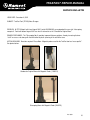
1
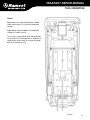
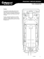
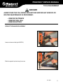
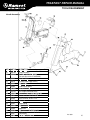
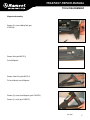
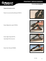
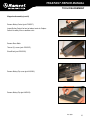
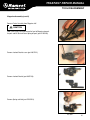
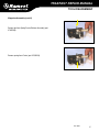
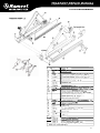
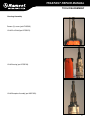
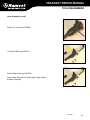
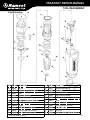
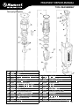
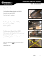
TRAKFAST REPAIR MANUAL Tool Repair Manual TRAKFAST REPAIR MANUAL TABLE OF CONTENTS Safety Instructions. . . . . . . . . . . . . . . . . . . . . . . . . . . . . . . . . . . . . . . . . . . . . . . . . . . . . . . . . . . . . . . . . . . . . . . . . 3 Tool Operation Overview. . . . . . . . . . . . . . . . . . . . . . . . . . . . . . . . . . . . . . . . . . . . . . . . . . . . . . . . . . . . . . . . . . . . . . . . . . . . . 6 Start and Pre-Combustion . . . . . . . . . . . . . . . . . . . . . . . . . . . . . . . . . . . . . . . . . . . . . . . . . . . . . . . . . . . . . . . 7 Combustion . . . . . . . . . . . . . . . . . . . . . . . . . . . . . . . . . . . . . . . . . . . . . . . . . . . . . . . . . . . . . . . . . . . . . . . . . . 8 Power/Exhaust. . . . . . . . . . . . . . . . . . . . . . . . . . . . . . . . . . . . . . . . . . . . . . . . . . . . . . . . . . . . . . . . . . . . . . . . 9 Return. . . . . . . . . . . . . . . . . . . . . . . . . . . . . . . . . . . . . . . . . . . . . . . . . . . . . . . . . . . . . . . . . . . . . . . . . . . . . . 10 Purging. . . . . . . . . . . . . . . . . . . . . . . . . . . . . . . . . . . . . . . . . . . . . . . . . . . . . . . . . . . . . . . . . . . . . . . . . . . . . 11 Preparing Tool for Operation — Battery/Charger Troubleshooting . . . . . . . . . . . . . . . . . . . . . . . . . . . . 12 Tool Disassembly Handle Assembly - part 1. . . . . . . . . . . . . . . . . . . . . . . . . . . . . . . . . . . . . . . . . . . . . . . . . . . . . . . . . . . . . . . 13 Motor/Cylinder Head Assembly. . . . . . . . . . . . . . . . . . . . . . . . . . . . . . . . . . . . . . . . . . . . . . . . . . . . . . . . . . . 16 Handle Assembly - part 2. . . . . . . . . . . . . . . . . . . . . . . . . . . . . . . . . . . . . . . . . . . . . . . . . . . . . . . . . . . . . . . 21 Magazine Assembly . . . . . . . . . . . . . . . . . . . . . . . . . . . . . . . . . . . . . . . . . . . . . . . . . . . . . . . . . . . . . . . . . . . 27 Housing Assembly . . . . . . . . . . . . . . . . . . . . . . . . . . . . . . . . . . . . . . . . . . . . . . . . . . . . . . . . . . . . . . . . . . . . 33 Nose Assembly. . . . . . . . . . . . . . . . . . . . . . . . . . . . . . . . . . . . . . . . . . . . . . . . . . . . . . . . . . . . . . . . . . . . . . . 37 Tool Reassembly Magazine Assembly . . . . . . . . . . . . . . . . . . . . . . . . . . . . . . . . . . . . . . . . . . . . . . . . . . . . . . . . . . . . . . . . . . . 41 Handle Assembly - part 2. . . . . . . . . . . . . . . . . . . . . . . . . . . . . . . . . . . . . . . . . . . . . . . . . . . . . . . . . . . . . . . 45 Housing Assembly . . . . . . . . . . . . . . . . . . . . . . . . . . . . . . . . . . . . . . . . . . . . . . . . . . . . . . . . . . . . . . . . . . . . 50 Nosepiece Assembly (original Nosepiece) . . . . . . . . . . . . . . . . . . . . . . . . . . . . . . . . . . . . . . . . . . . . . . . . . . 56 Nosepiece Assembly (Telescoping Nosepiece). . . . . . . . . . . . . . . . . . . . . . . . . . . . . . . . . . . . . . . . . . . . . . . 57 Troubleshooting Guide. . . . . . . . . . . . . . . . . . . . . . . . . . . . . . . . . . . . . . . . . . . . . . . . . . . . . . . . . . . . . . . . . . . . 60 NOTE: This manual is intended for use by professional Technicians only, not a “do-it-yourselfer”. It is written to inform the technician on proper repair. Properly trained Technicians have the equipment, tools, safety instructions and know-how to do a job properly and safely. Rev. 09/07 TRAKFAST REPAIR MANUAL • • • • • • • • • • • • • 5/32” Hex Key Inside Snap Ring Pliers Outside Snap Ring Pliers #2 Phillips Screwdriver T15 Torx Screwdriver T25 Torx Screwdriver T7 Torx Screwdriver Flat Blade Screwdriver Needle Nose Pliers Lubricating Oil Loctite #343 Blue RTV Silicone Volt/Ohm Meter (is helpful) Rev. 09/07 TRAKFAST REPAIR MANUAL SAFETY INSTRUCTIONS The following safety instructions have been included to provide you with information necessary for safe operation of the TrakFast Tool. WARNING HIERARCHY WARNING DANGER Failure to follow all instructions may result in severe personal injury or substantial damage to tool and/or personal property. WARNING When servicing tool, stay clear of high voltage ignition cable. High voltage may be present in unexpected areas with malfunctioning tools. Failure to follow all instructions may result in injury or damage to tool and/or personal property. DANGER CAUTION Failure to follow all instructions may result in minor injury or damage to tool. DANGER Do not attempt to operate this tool until you have read and understand all safety precautions and manual instructions. DANGER The TrakFast tool is an internal combustion devise. It produces hot exhaust gases that may ignite flammable materials. Do not expose the tool to temperatures in excess of 120 degrees F (48 degrees C). Fuel and/or the battery cell may burst, releasing flammable gas. DANGER Operate the tool ONLY in a well ventilated area. Exposure to carbon monoxide may cause dizziness, nausea or unconsciousness. DANGER ALWAYS keep the TrakFast tool, fuel cell, battery and battery charger out of the reach of children. Rev. 09/07 TRAKFAST REPAIR MANUAL SAFETY INSTRUCTIONS 1. Wear eye and ear protection. DANGER 9. ALWAYS point the tool away from yourself and others when clearing jams or removing fasteners. Always wear EYE and EAR safety gear when working with or in the vicinity of the TrakFast tool. 2. ALWAYS assume the tool is “loaded”. 3. DON’T treat the TrakFast tool as a toy. The TrakFast tool is not a toy — it is a tool. Careless and improper use may result in a serious accident. The fastener may be accidently discharged. Pull the follower slightly back and push the release lever. Tip the tool nose up slightly and fasteners should slide out of the rear of the magazine. If fasteners are jammed, refer to the appropriate service section of this manual. 10. NEVER attempt to operate the TrakFast tool if parts are loose, damaged or missing. 11. DO NOT drive fasteners too close or on top of other fasteners. A fastener may ricochet and cause serious injury. 4. NEVER carry the tool with your finger on or pressing the trigger. 12. NEVER drive fasteners into areas with concealed hazards. This practice may result in the accidental discharge of a fastener. 5. NEVER operate a malfunctioning tool. Refer to the service section of this manual to correct the problem. If the problem cannot be corrected, report it to your supervisor or ITW Ramset Distributor Sales Representative. Always check the area behind the work surface for electrical wiring, gas pipes, water pipes, sewer drains or other potential hazards. 13. ALWAYS maintain secure and unobstructed footing when on ladders, platforms or other high locations. DANGER 6. Operate the tool ONLY on the work surface. WARNING The TrakFast tool should be operated only when it is in contact with the work surface. 7. NEVER remove or disable the lower probe. This device helps reduce the possibility of accidental fastener discharge by preventing the tool from operating until it is completely against the work surface. NEVER operate the tool if the work lower probe is not working properly. 8. DO NOT load fasteners with the trigger and/or lower probe pressed in. Never overreach, since tool recoil may cause a loss of balance. Always be aware of edges and drop-offs. Keep them in full view 14. Allow ONLY qualified personnel to operate the TrakFast tool. DANGER Only persons who have read and fully understand all tool operation, safety and maintenance instructions should be allowed to operate the tool. Rev. 09/07 TRAKFAST REPAIR MANUAL SAFETY INSTRUCTIONS 15.Fuel Cell Storage DANGER Always store fuel cells where they will not be exposed to an open flame, sparks or temperatures above 120 degrees F (48 degrees C). 16. ALWAYS store the tool with the fuel cell removed. 6. Insert the battery, contact side down, into the charger and depress red button. The green light will go out and the red light will come on, indicating the battery is charging. 7. The green light comes on again when the battery is fully charged. The time required to fully charge a battery: First charge 24 hours Completely Discharged 3 hours Partially Discharged Depends on discharge level of battery 17. Keep the tool clean. 8. Do not allow metal objects to come in contact with the battery terminals. 18. Keep your hands clear of the work area surface. 9. Do not puncture or attempt to open the battery cell. 10. Do not store the battery in location where temperatures exceed 120 degrees F (48 degrees C). WARNING A fastener may exit at an angle unexpectedly and cause injury. 11. Do not incinerate the Battery. FUEL CELL DANGER BATTERY CELL AND CHARGER DANGER CHEMICAL/EXPLOSION HAZARD Read ALL instructions before charging or using the battery. Failure to follow ALL instructions may result in fire, severe burns and/or release of toxic materials. 1. Keep the battery charger upright for proper operation. 2. Only charge the battery indoors. 3. Do not charge the battery when the battery temperature is below 40 degrees F (5 degrees C). 4. Do not use a defective battery charger, one that overheats and/or smokes when plugged in. 5. Plug the battery charger into a 120V AC outlet only. A blue light indicates that power is on and that charger circuit is ready. EXPLOSION/FIRE HAZARD Read all safety instructions before using or handling the fuel cell. Failure to follow ALL instructions may result in explosion or fire. This may cause severe personal injury or property damage. Keep the fuel cell away from heat, sparks and open flame. Do not puncture or attempt to open the fuel cell; it is non-refillable. Do not incinerate, reclaim or recycle the fuel cell. Exposure to temperature above 120 degrees F (48 degrees C) may cause the fuel cell to burst, releasing flammable gas. Do not smoke while installing/operating the metering valve. Never spray toward the face or eyes. Do not inhale the spray. Keep out of the reach of children. Store fuel cell(s) in well ventilated areas only. WARNING Nickel Cadmium Rechargeable Battery. Must be recycled or disposed of properly. NOTE: DEAD BATTERY MUST BE RETURNED TO YOUR LOCAL TRAKFAST DISTRIBUTOR FOR PROPER DISPOSAL. Rev. 09/07 TRAKFAST REPAIR MANUAL TOOL OPERATION OVERVIEW Magazine Assembly The magazine assembly has two functions. Its primary function is to store and feed fasteners into the nose of the tool. Its secondary function is to house the battery and battery contact assembly. This assembly generates and controls forces that drive the fasteners. It will require the majority of routine service and/or repair. • Piston Assembly • O-Rings Motor Assembly Handle Assembly The motor assembly is made up of components that: The handle assembly contains electrical components, and the fan motor and fan. The electrical components provide spark for combustion. The fan mixes fuel with air and also cools the motor. • Control the piston assembly • Control intake of the fuel/air mixture • Vent exhaust gases Cover and Filters Fuel Cell Compartment Battery LED Indicator Light (opposite side) HANDLE ASSEMBLY Magazine Locking Knob Motor Housing Trigger MOTOR ASSEMBLY MAGAZINE ASSEMBLY Nose Follower Release Lever Follower Battery Compartment (opposite side) Lockout Bar Rev. 09/07 TRAKFAST REPAIR MANUAL TOOL OPERATION START and PRE-COMBUSTION When lower probe (E) is pressed against the work surface, cage (F) is forced against the spring (G). Combustion chamber (H) is raised up against cylinder head (I), and O-Rings (J & M) seal off the combustion chamber, creating an air tight seal. This initial movement, pressing the lower probe against the work surface, causes the fuel cell/metering valve assembly to pivot. This meters a precise amount of fuel through the cylinder head and into the combustion chamber cavity (K). As the combustion chamber is raised, fan/enable switch (L) is depressed and the chamber lockout bar is moved out of the way of the cam. The fan starts and mixes air with a metered amount of fuel to provide a combustible mixture. The chamber lockout bar prevents the trigger from being activated until the lower probe is pressed against the work piece, raising the combustion chamber. Rev. 09/07 TRAKFAST REPAIR MANUAL TOOL OPERATION Combustion Depressing the trigger activates the ignition circuit. This causes a spark (N) to jump the gap between the spark element and cylinder head, igniting the fuel/air mixture in the combustion chamber. Piston assembly (O) is forced downward driving the fastener into the work surface. Rev. 09/07 TRAKFAST REPAIR MANUAL TOOL OPERATION Power/Exhaust Downward movement of the piston assembly, past exhaust ports (P), allows exhaust gases to exit. The pressure of the exhaust gases against the flat washer compresses the wave washers, allowing the gases to flow through the mid-check area (Q) and out of the tool through the exhaust ports in the bottom of the housing (R). At the bottom of stroke, the piston assembly strikes bumper (S). Rev. 09/07 TRAKFAST REPAIR MANUAL TOOL OPERATION Return Reduced pressure within the combustion chamber allows wave washers (T) to reseal the combustion chamber. Rapid cooling of gases trapped in the combustion chamber (U) creates vacuum. This vacuum is strong enough to lift and hold the piston assembly in its starting position. As the piston assembly moves up the sleeve, air is drawn in through ports in the housing nose (V). Rev. 09/07 10 TRAKFAST REPAIR MANUAL TOOL OPERATION Purging The combustion chamber drops when the tool is lifted from the work surface and the trigger is released. This opens the seal between the combustion chamber and cylinder head O-Ring (W) and sleeve O-Ring (X). The fan is now able to circulate fresh air into the combustion chamber, cooling the sleeve (Y) and purging any remaining exhaust gases from the tool through ports (Z). Rev. 09/07 11 TRAKFAST REPAIR MANUAL TROUBLESHOOTING Preparing Tool for Operation — Battery/Charger Problems SYMPTOM Battery Cell doesn’t appear to accept charge — green Charger light does not come on — red Charger light comes on when Battery Cell is inserted in Charger. Battery is inserted into Charger and no red LED. POSSIBLE PROBLEMS SERVICE Inoperative indicator lights on Charger. Try Battery Cell in tool after charge cycle. If tool LED is green, Charger lights are not working properly. Replace Charger or monitor charging time to ensure Battery Cell has adequate time for recharging. If tool LED is red or is off, check Charger output voltage. Battery Cell damaged or cycle life exhausted. Replace Battery Cell. Check power to Charger. Rotate Battery Cell in Charger holding red button down until red light comes on. Battery Charger lights flash red/green. Battery Cell left in completely discharged state for extensive time. Place Battery Cell in Charger for 3 hours, then try in tool. If tool LED still indicates red, replace Battery Cell. Battery Cell won’t fit in Charger open- Battery Cell case or label is damaged. ing freely. Remove raised burrs or replace label. Do not use Battery Cell if plastic case is cracked or severely damaged. Blue Charger light won’t come on when Charger is plugged in; red light won’t come on when discharged Battery Cell is inserted. Defective indicator light(s) and/ or Charger. Check Charger output voltage. Make sure Charger is plugged into an energized 110V outlet. Blue Charger light comes on when Charger is plugged in; red light won’t come on when discharged Battery Cell in inserted. Battery Cell not completely inserted into Charger. Check terminal end of battery for burrs on tube or scuffed label. Service as required. Replace severely damaged Battery Cell. Terminals in Charger not making contact with Battery Cell. Unplug Charger and check if terminals are O.K. If not, replace Charger. Damaged Charger. Discontinue use immediately and unplug from power source. Replace Charger and tag. Dispose of Charger to prevent accidental use. Charger gets hotter than normal, makes excessively loud noise, or smokes during charging cycle. Charger cord or wall plug gets hotter than normal. Rev. 09/07 12 TRAKFAST REPAIR MANUAL TOOL DISASSEMBLY DANGER ALWAYS TAKE THE FOLLOWING PRECAUTIONS BEFORE ANY SERVICE OR ROUTING MAINTENANCE IS PERFORMED: • REMOVE FASTENERS • REMOVE FUEL CELL • REMOVE BATTERY REMOVE THE MAGAZINE ASSEMBLY Loosen and remove knob (part #801124). Slide the magazine back and away from nose. Rev. 09/07 13 TRAKFAST REPAIR MANUAL TOOL DISASSEMBLY REMOVE HANDLE ASSEMBLY (Part 1) Lift off cap, grill and filter with screw driver. Loosen four screws using a 5/32” hex key (Part # 7405061). Lift off cap assembly (Part # 401365). Rev. 09/07 14 TRAKFAST REPAIR MANUAL REMOVE HANDLE ASSEMBLY (Part 1) Remove Screw at bottom of Handle Assembly (Part # 7405065). Remove Cam Bushing.(Part # 401397). Push Cam Bushing out of Handle from side where the Screw was removed. Rev. 09/07 15 TRAKFAST REPAIR MANUAL TOOL DISASSEMBLY REMOVE MOTOR ASSEMBLY Pull Handle Assembly away from Motor Assembly until fan clears combustion chamber assembly. Do not scratch combustion chamber walls with fan blades. Set Handle Assembly down carefully so that Fan Blades are not damaged and Fan Motor Shaft is not bent. When removing handle from housing, be sure not to bend fan blades. CAUTION Be sure leads and connectors are positioned so that leads are not pinched when installing cap. WARNING DO NOT operate tool until all screws are tightened. DANGER NEVER attempt to operate tool without cap assembly securely fastened. Cap assembly secures cylinder head to combustion chamber. Operating TrakFast with cap assembly off or loose will cause burning fuel to escape through top of tool, causing burns and damage to tool. Rev. 09/07 16 TRAKFAST REPAIR MANUAL TOOL DISASSEMBLY Motor/Cylinder Head Assembly Torque Head Switch to 5-10 in-lbs. Torque Spark Plug to 20-25 in-lbs. Install Stem Adapter as illustrated. Notice the difference between one end of the Sleeve to the other. One side of the sleeve has a rib. The other side does not. The ribs should be to the inside and should touch the fan motor. **CRITICAL** Install the Motor Sleeve as illustrated. Pay careful attention to the orientation of the “split” which is pointing at the Spark Plug and how the ends of the Motor Sleeve face each other. This process determines how well the motor shaft will be centered after the motor is inserted. Rev. 09/07 17 TRAKFAST REPAIR MANUAL Motor/Cylinder Head Assembly (cont’d) Apply a small amount of oil or lubricant to the inside of the bore where the Fan Motor is positioned. Insert Motor Assembly as illustrated. The Motor Sleeve orientation will determine how well the spacing will be around the shaft. Make sure that it is equally spaced all the way around. SOMETIMES you may have to adjust the Motor Sleeve clockwise or counterclockwise to help center the shaft. Rev. 09/07 18 TRAKFAST REPAIR MANUAL TOOL DISASSEMBLY Motor/Cylinder Head Assembly (cont’d) Make sure the “flat” side of the shaft is where the Set Screw on the Fan Blade will be tightened. Position the Fan Blade approximately .120” away from the bottom of the cylinder head. Feeler Gages or an 1/8” drill bit works well as a spacer. Carefully place the Fan Blade until it is flat and leveled over the Fan Blade Spacer. Tighten Set Screw no more than 8 to 10 in-lbs of torque. Rev. 09/07 19 TRAKFAST REPAIR MANUAL TOOL DISASSEMBLY CYLINDER HEAD ASSEMBLY KEY PART NO. DESCRIPTION 1 401365 Cap, grill & filter assembly 3 7505018 Foam filter only 4 901065A Screw kit, #10-24 x 1-1/4” Sems (pkg. 4) 8 900271 P.C board assembly 8A 7405090 P.C board screw & washer, #8-32 x 1/2” (pkg. 3) 11 900525A Fan motor kit** 12 7505166 MSU spark wire & boot only 12A 404397 Spark plug boot only (for 401341 plug) 13 7505164 Black spark plug (with O-Ring) (for tools after serial no. 39809144) 13A 401341 Red spark plug (with 0-Ring) 15 401356 Motor sleeve 16 900470 Motor mount 17 401355 Motor retaining ring 18 404601 Head switch assembly 20 401340 Red stem adaptor 21 401336 Cylinder head 22 403992 O-Ring (cylinder head) 23 403167 Fan blade (with set screw) Note: It is important to use all kit parts when replacing the fan motor. Failure to do so will greatly reduce the life of the motor. ** The Fan Motor Kit includes: Fan Motor, Motor Mount, Motor Sleeve, Snap Ring and Fan Blade. Rev. 09/07 20 TRAKFAST REPAIR MANUAL TOOL DISASSEMBLY Handle Assembly (part 2) Remove Trigger Cam (part #401396). Remove Belt Hook and screw. (screw, part #7405065) (Belt Hook, part #401495) Remove (3) screws (part #7405067). Remove (1) screw (part #7405066). Lift off Handle half. Remove Actuator Assembly (part #401400A). Rev. 09/07 21 TRAKFAST REPAIR MANUAL TOOL DISASSEMBLY Handle Assembly - Part 2 (cont’d) Remove Trigger and Spring from Handle. (Trigger, part #401394A) (Spring, part #401395) Remove Trigger Switch with screw driver. Undo the two screws and lift out. Unplug from the Spark Unit. (Trigger Switch, part #404990) (Trigger screws, part #7405091) Using a Phillips screw driver, remove screw. This will disconnect the Handle from the Cylinder Head (part #7405065). Lift out wire Cover Plate (part #900012). Rev. 09/07 22 TRAKFAST REPAIR MANUAL TOOL DISASSEMBLY Handle Assembly - Part 2 (cont’d) Lift up Spark Plug wire and remove from Handle half (part #7505166). Unplug Spark Wires from Spark Unit. Lift up with screw driver to remove Spark Unit (part #7405163). Note: MSU Spark Units are held in place with silicone. Disconnect Head Switch from P.C. Board (part #404601) and unscrew Head Switch. Rev. 09/07 23 TRAKFAST REPAIR MANUAL TOOL DISASSEMBLY Handle Assembly - Part 2 (cont’d) Remove Fan Blade Set Screw (requires #T-7). (Fan Blade part #403167 with screw) With Phillips screw driver remove (3) screws (part #7405090) holding P.C. Board. Unplug Fan Connector. Pull out red Stem Adapter (part #401340). Lift up O-Ring and remove (part #403992). Inspect O-Ring. Replace is any damage is noted. Rev. 09/07 24 TRAKFAST REPAIR MANUAL TOOL DISASSEMBLY Handle Assembly - Part 2 (cont’d) Remove Spark Plug (part #7505164). Fan Motor Kit (part #900525A). See inserts for Motor/Cylinder Assembly. Rev. 09/07 25 TRAKFAST REPAIR MANUAL TOOL DISASSEMBLY Handle Assembly KEY PART NO. DESCRIPTION 52 7405163 Spark Unit (MSU) 52A 7505166 Red Wire and Boot Only (MSU) (For tools after serial no. 398091440) 53 900012 Wire Cover Plate 54 404619 Insulator (under Trigger Switch) 55 404490 Trigger Switch 56 403999 Handle Contact Board 59 401400A Actuator Assembly 61 7405148 Left & Right Side Handle Halves 62 7405067 Screws & washers, #6-32 x 1” (pkg. 3) 63 401408 Screw & washer, #10-32 x 9/16” 64 401406 Screw & washer, #6-32 x 1-1/2” 66 401495 Belt Hook 69 401395 Trigger Spring 70 401394A Trigger Assembly 72 401396 Trigger Cam 73 7405091 Trigger Screws, #2 x 5/8” (pkg. 2) 75 401397 Cam Bushing 401450 Fuel Cell Pad (not shown) Rev. 09/07 26 TRAKFAST REPAIR MANUAL TOOL DISASSEMBLY Magazine Assembly Remove (2) screws holding Foot (part #7505146). Remove Foot (part #801113). Pull off Magazine. Remove Lower Rail (part #801110). Pull and slide out rear of Magazine. Remove (3) screws from Magazine (part #7405070). Remove (1) screw (part #7405071). Rev. 09/07 27 TRAKFAST REPAIR MANUAL TOOL DISASSEMBLY Magazine Assembly (cont’d) Remove (2) screws from Shear Block (part #7405147). Remove Magazine halves (part #7405149). Remove Upper Rail (part #801112). Inspect Upper Rail for heavy burrs. Remove Cover Plate (part #7506006). Rev. 09/07 28 TRAKFAST REPAIR MANUAL TOOL DISASSEMBLY Magazine Assembly (cont’d) Remove Battery Contact (part #7505017). Inspect Battery Contact for bent or broken terminals. Replace Contact Assembly if these conditions exist. Remove Shear Block. Take out (2) screws (part #7405147). Shear Block (part #7405145). Remove Battery Clip screw (part #401423). Remove Battery Clip (part #401422). Rev. 09/07 29 TRAKFAST REPAIR MANUAL TOOL DISASSEMBLY Magazine Assembly (cont’d) Remove Carrier Assembly from Magazine half. CAUTION Hold Carrier firmly and slide forward to front of Magazine towards the post and lift Constant Force Spring off post (part #7405168). Remove Lockout Bracket screw (part #801122). Remove Lockout Bracket (part #801106). Remove Spring and Hub (part #7405169). Rev. 09/07 30 TRAKFAST REPAIR MANUAL TOOL DISASSEMBLY Magazine Assembly (cont’d) Remove pin from Spring Carrier/Follower Assembly (part #7405168). Remove spring from Carrier (part #7405168). Rev. 09/07 31 TRAKFAST REPAIR MANUAL TOOL DISASSEMBLY Magazine Assembly KEY PART NO. DESCRIPTION 801114 7405070 Screws and washers, #6-32 x 3/4” (pkg. 3) 7405071 Screws and washers, #6-32 x 1/2” (pkg. 3) 7405146 Constant force spring with hub 801126 801118 93 Shear block (for Telescoping Nosepiece tools) (for Original Nosepiece tool) Pre August 2001 7405147 Shear block screws & washers only 7405149 Left & right magazine halves (with battery clip) 7505017 401422 Battery clip screw, #6-32 x 1-1/4” 7506006 801112 101 801110 103 Follower/Lockout assembly complete *screws use Loctite 242 (Blue) Rev. 09/07 TRAKFAST REPAIR MANUAL TOOL DISASSEMBLY Housing Assembly Remove (3) screws (part #7405060). Lift off Dust Shield (part #7505013). Lift off Housing (part #7505148). Lift off Nosepiece Assembly (part #801130A). Rev. 09/07 33 TRAKFAST REPAIR MANUAL TOOL DISASSEMBLY Housing Assembly (cont’d) Remove Piston Stop Retaining Ring (part #401328), using Snap Ring pliers (part #401333). Make sure when you reassemble that Retaining Ring ends are not positioned in the vertical notches in the Sleeve. Slide Piston out of Mid-check Assembly (part #7502000). Lift off Air Dam (part #401313). Check position of Air Dam when reassembling. Note notches in the Air Dam. Remove (4) Cage screws (part #092769). Rev. 09/07 34 TRAKFAST REPAIR MANUAL TOOL DISASSEMBLY Housing Assembly (cont’d) Slide off Cage and Spring. (part #7405144 only comes as an assembly) (Spring, part #401488) Lift out Mid-check Retaining Ring (part #401322). Remove with Snap Ring Pliers (part #401333). Remove 2 Wave Washers and 1 Seal Washer (part #7405056). Remove Bumper (part #7505109) using Bumper Removal Tool. Rev. 09/07 35 TRAKFAST REPAIR MANUAL TOOL DISASSEMBLY Housing Assembly (cont’d) Lift off O-Ring (part #404482). Lift off Piston Rings (part #7405055). Always make sure the Piston Ring end gaps are opposite each other. Rev. 09/07 36 TRAKFAST REPAIR MANUAL TOOL DISASSEMBLY Nose Assembly Remove (2) screws (part #7405059). Lift off Stop Plate (part #801127). Lift off Lock-out Probe (part #801128). Lift off Work Contact Element (part #801129). Inspect Work Contact Element for burring or damage. Replace if burring or damage is noted. Rev. 09/07 37 TRAKFAST REPAIR MANUAL TOOL DISASSEMBLY Nose Assembly (cont’d) Remove (2) screws (part #7405059). Lift off Guide Block (part #801131). Slide out Upper Probe (part #801132). Inspect rubber Grommet for damage. Replace Upper Probe if grommet is damaged. Rev. 09/07 38 TRAKFAST REPAIR MANUAL TOOL REASSEMBLY Original Nosepiece A KEY PART NO. DESCRIPTION KEY PART NO. DESCRIPTION 24 401313 Air Dam 34 401322 Mid-Check Retaining Ring 25 7405171 Combustion Chamber (w/Air Dam) 35 401488 Cage Spring 25A 900234 Cage 37* 092769 Screw, #10-32 x 1/4” 26 401330 Chamber Lockout Bar 38 7405057 Upper Probe with Grommet 27 401328 Piston Stop Retaining Ring 40 7405058 Roll Pins (for Nosepiece Assembly) (pkg. 2) 28 7502000 Piston Assembly (with Piston Rings) 41 401380 Tie Bar 29 7405055 Piston Rings (pkg. 2) 42 801114A Nosepiece Assembly 30 7505109 Bumper 43* 7405059 Screw Kit, #10-32 x 3/8” SEMS 31 404482 O-Ring (Sleeve and Mid-Check 45 7505148 Housing with labels 32 403083 Sleeve and Mid-Check Assembly 46 7505013 Dust Shield 33 7405056 Seal (1) and Wave Washers (2) 47* 7405060 Cap Screw & Washer, #10-24 x 1” (pkg. 3) * screws use Loctite 242 (Blue) Rev. 09/07 39 TRAKFAST REPAIR MANUAL TOOL REASSEMBLY Telescoping Nosepiece A KEY PART NO. DESCRIPTION 24 401313 Air Dam 25 7405171 Combustion Chamber (w/Air Dam & Cage) KEY PART NO. DESCRIPTION 25A 900234 Cage 37* 092769 Screw, #10-32 x 1/4” 26 401330 Chamber Lockout Bar 38 801132 Upper Probe with Grommet 27 401328 Piston Stop Retaining Ring 39 801130A Nosepiece Assembly 28 7502000 Piston Assembly (with Piston Rings) 40 801131 Guide Block 29 7405055 Piston Rings (pkg. 2) 41 801127 Stop Plate 30 7505109 Bumper 42 801129 Work Contact Element 31 404482 O-Ring (Sleeve and Mid-Check 43* 7405059 Screw Kit, #10-32 x 3/8” SEMS 32 403083 Sleeve and Mid-Check Assembly 44 801128 Lockout Probe 33 7405056 Seal (1) and Wave Washers (2) 45 7505148 Housing (with labels) 34 401322 Mid-Check Retaining Ring 46 7505013 Dust Shield 35 401488 Cage Spring 47 7405060 Cap Screws & Washers, #10-24 x 1” (pkg. 3) *screws - use Loctite 242 (Blue) Rev. 09/07 40 TRAKFAST REPAIR MANUAL TOOL REASSEMBLY Magazine Assembly Place Shear Block in Magazine Assembly (part #7405145). Secure with screws (part #7405147). Check Shear Block for any damage. Place Battery Clip in Magazine Half (part #401422). Secure with screw (part #401423). Check for any damage. Place Battery Contact in Magazine Half (part #7505017). Notice the position of the Battery Contact. Check for any damaged parts and compressed springs. Note: In the older style Magazine Assembly you may have to cut a place for the Battery Contact. Photo to the right shows incorrect placement of the Contact Assembly. Contact should sit flat. Rev. 09/07 41 TRAKFAST REPAIR MANUAL TOOL REASSEMBLY Magazine Assembly Place Cover Plate in Magazine Assembly (part #7506006). Notice position of notch. It should be placed toward the bottom/ rear of Magazine. Place Upper Rail in Magazine Half (part #801112). Check for any damage. Check ends of rail for any burrs and check to see if it is bent. Notice the position of the Upper Rail as it fits into the Shear Block. Place Carrier Assembly in between Magazine Half. Make sure Spring is placed in between the Handle Half so it will slide (part #7405168). Slide Carrier onto the Post. Check for any damage. Rev. 09/07 42 TRAKFAST REPAIR MANUAL TOOL REASSEMBLY Magazine Assembly Slide Carrier all the way back to the lock position (part #7405168). Place Magazine Halves together (part #7405149). Secure with screws . (part #7405070, 3 each) (part #7405071, 1 each) (Shear Block screws, part #7405147) Slide Lower Rail into Magazine Halves (part #801110). Check for any damage. Replace Foot (part #801113). Line up the screw holes. Replace (2) screws (part #7405146). Rev. 09/07 43 TRAKFAST REPAIR MANUAL TOOL REASSEMBLY Magazine Assembly TESTING OPERATION OF HANDLE ASSEMBLY Place Handle Assembly on to the Magazine Assembly. Screw on the Knob. This will hold the handle on the Magazine. Place Battery in Magazine. You will have a green light. If you have a red light, you will need to check the Battery or the Battery Contact. Put one finger on the Trigger Button and one finger on the Head Switch Button. Press these at the same time. The fan will start and you will see the spark. CAUTION Note: Keep fingers away from fan! Rev. 09/07 44 TRAKFAST REPAIR MANUAL TOOL REASSEMBLY Handle Assembly - part 2 Spark Unit (part #7405163). Remove any silicone residue from Handle. Place new silicone in Handle. Press Spark Unit into Handle. Replace the unit if it does not spark. Push red wire into Spark Unit and route the wires into the Handle. Insert red wire into Spark Unit noting position of black line. Make sure the wires are inside the grooves, and not pinched. If they are out of the grooves, the Fuel Cell will not sit properly in Handle. If Fuel Cell Pad is loose or missing, replace Fuel Cell Pad. Place Contact Board into Handle. Press all the wires into the grooves inside the Handle. Make sure there are no pinches wires that would break contact. Plug into the Spark Unit. Rev. 09/07 45 TRAKFAST REPAIR MANUAL TOOL REASSEMBLY Handle Assembly - part 2 Place plastic wire cover over wires. Make sure all wires are seated properly in handle.vva Place Trigger Switch on top of the wire cover. Secure with screws. Check for any damage. Press button to make sure it is not sticking. Plug into Spark Unit. Check all wires for damage. Place wire in Handle away from screw holes. Place Wire Cover over Spark Plug Wire and P.C. Board wires. Place Cylinder Head on top of Wire Cover and secure with screw. Rev. 09/07 46 TRAKFAST REPAIR MANUAL TOOL REASSEMBLY Handle Assembly - part 2 Replace screw if damaged, or if washers are missing. If washers are missing the fuel cell will not sit in handle properly, causing a misfire. Replace cylinder head if cracked or broken. Replace O-Ring after cleaning, worn or pinched. Drop oil on O-Ring. ONLY use TrakFast oil or Paslode Impulse oil (do not use grease). Replace Fan Blade if bent or if replacing the Fan Motor. Place Spring in Trigger. Replace if Spring is compressed. Place Trigger in Handle. Note the position of the Spring. Do not place on Trigger Switch Button. Rev. 09/07 47 TRAKFAST REPAIR MANUAL TOOL REASSEMBLY Handle Assembly - part 2 Place Actuator inside the Handle. Note the position of the handle. Replace if broken or damaged. Check all wires before placing Handle half. Secure with screws. Pull Trigger to make sure it is in correct position. Place Belt Hook on Handle. Secure with screw. Check to make sure that the washers are on the screw and Cylinder Head is straight. If removing Belt Hook, always replace the screw and washers back in the Handle half. This keeps Cylinder Head in position. Note: If washers are not used or an incorrect screw is used, this may restrict movement of Fuel Cell causing an inoperative tool. Rev. 09/07 48 TRAKFAST REPAIR MANUAL TOOL REASSEMBLY Handle Assembly - part 2 Place Handle half on Magazine Assembly. Place Battery in Magazine. For testing, push Head Switch then pull Trigger. This will activate the Fan Motor and Spark Unit. CAUTION Keep fingers away from Fan! Rev. 09/07 49 TRAKFAST REPAIR MANUAL TOOL REASSEMBLY Housing Assembly Place Bumper inside chamber. If Bumper is loose inside the chamber, replace with new one. The Bumper is marked “top”. It should be oriented so the word “top” is visible. Replace O-Ring if it has been pinched, worn or after cleaning. Lubricate the O-Ring with TrakFast or Paslode Impulse oil (DO NOT use grease). • Install Flat Seal Washer • Install 2 Wave Washers • Install Retaining Ring Replace Flat and Wave Washers and clean Mid-Check area if tool does not fire overhead, and Piston does not return. Be sure Mid-Check area is clean below Seal and Mid-Check washers. The seal of the flat washer is added first, followed by two Wavy Washers then the Snap Ring. A Mid-Check honing tool is available to “true” up the sealing surface for the Flat Seal Washer. Rev. 09/07 50 TRAKFAST REPAIR MANUAL TOOL REASSEMBLY Housing Assembly - (cont’d) Slide the Combustion Chamber on to Sleeve Mid-Check Assembly. Check for any damage on parts. Lubricate sealing surfaces on Combustion Chamber with TrakFast or Paslode oil prior to assembling the sleeve. Place Lockout Bracket in holes. Line up the cross on the Sleeve with holes for the Lockout Bracket. Slide together. Check Air Dam for any damage. The widest notch in the Air Dam lines up with the Lockout Bracket. Place Spring on bottom of Sleeve Assembly. Place Cage over Sleeve. Check parts for any damage. Secure with screws, using a T-25. Apply Blue #242 Loctite to screw threads. Rev. 09/07 51 TRAKFAST REPAIR MANUAL TOOL REASSEMBLY Housing Assembly - (cont’d) Note orientation of Cage on the Sleeve. Check Piston to see if it is bent or tip is worn. Check Piston Rings for damage. Clean inside the grooves. Check to make sure Piston is not too short. If length is too short, the tool will not shoot overhead or drive fasteners properly. Lubricate Piston Rings and inside of Sleeve Bore with TrakFast or Paslode Impulse oil prior to assembly. Place Piston inside Sleeve. Always make sure Piston Ring end gaps are opposite of each other. Tap downward. With large Snap Ring Pliers, place Retaining Ring into position. Note: Do not place ends of retaining rings in the vertical notches. Rev. 09/07 52 TRAKFAST REPAIR MANUAL TOOL REASSEMBLY Housing Assembly - (cont’d) Place Nosepiece Assembly on Mid-check Assembly. Note how parts line up. Slide Housing over Nosepiece and Mid-check Assembly. Note the position of the Lockout Bar. Slide Dust Shield over Nosepiece. Secure with screws. Replace if torn or missing. Do not use tool without Dust Shield. This would cause dust to from inside the tool. Place Cam inside Handle Note the position of the hole. Rev. 09/07 53 TRAKFAST REPAIR MANUAL TOOL REASSEMBLY Housing Assembly - (cont’d) Slide Handle Assembly into Housing. Keep Handle Assembly straight so that the fan does not hit the inside of Chamber. Line up Cam with Housing. Place Cam Bushing inside the Cam and Housing. Note position of Cam in Housing. Secure with screw. Screwdriver or similar tool may be needed to help align Trigger Cam. Be sure Cam Bushing goes through hole in Trigger Cam and the hex head of the Bushing is properly seated in the hex recess on the Handle. Place Cap Assembly on Housing. Replace any damaged parts. Secure with screws. Replace Foam Filter if dirty or torn. Rev. 09/07 54 TRAKFAST REPAIR MANUAL TOOL REASSEMBLY Housing Assembly - (cont’d) Place Grill on Cap Assembly. Slide in and tap down. Place Shear Block into Nosepiece. Slide Magazine onto Handle/Housing Assembly. Secure Magazine Assembly and Housing together with Knob. Place Battery in Tool. Slide Carrier back into lock position. Press down on Nosepiece. Motor will come on. Rev. 09/07 55 TRAKFAST REPAIR MANUAL TOOL REASSEMBLY Nosepiece Assembly — Original Nose Original Nose piece (part #801114A). Roll pins (part #7405058). Check for any damage. Replace Roll Pins if loose. Slide Lower Probe in Nosepiece (part #7505057). Replace Probe if bent or grommet is worn or missing. Slide Tie Bar into Nosepiece. Line up with holes. Place screws into Lower Probe and Tie Bar. Line up holes and make sure the Lower Probe is fully extended downward. Probe must be all the way extended or tool will not fire. Secure with Locking Washers and screws. Put Loctite 242 (Blue) on screw threads. Some probes could be adjusted for length adjust for 3 of the teeth showing. Rev. 09/07 56 TRAKFAST REPAIR MANUAL TOOL REASSEMBLY Nosepiece Assembly — Telescoping Nose Telescoping Nosepiece Assembly (part #801130A). Check for any damage. Nose and Flange should be tight and without movement. Slide Lower Probe into Nosepiece. Replace Probe if bent or grommet is worn or missing. Place Guide Block in Nosepiece. Secure with screws. Check for damaged parts. Rev. 09/07 57 TRAKFAST REPAIR MANUAL TOOL REASSEMBLY Nosepiece Assembly — Telescoping Nose Slide Lockout Probe onto Work Element. Check for any damage. If the Work Element is burred, the fasteners will not flow into the firing position. Slide Lockout Probe and Work Element onto the Nosepiece. Place Stop Plate on Nosepiece. Secure with screws. Use Loctite #242 (Blue) on screw threads. Rev. 09/07 58 TRAKFAST REPAIR MANUAL SERVICE BULLETIN ISSUE DATE: December 4, 2001 SUBJECT: TrakFast Tool (TF1100) Nose Changes REVISION: All TF1100 tools built since August 2001 (serial #301080281) are equipped with a new style “telescoping nosepiece”. Tools built before August 2001 use what is referred to as the “Standard or Original Nose”. REASON FOR CHANGE: The “Telescoping Nose” provides improved fastener guidance, thereby increasing fastener “stick” or success rate along with the elimination of plastic jamming in the end of the nose. ACTION REQUIRED: No action required. Please Note: Magnetic probes used for the TrakFast tool are “nose specific”. See photos below. Standard or Original Nose with Magnetic Probe (7405151) Telescoping Nose with Magnetic Probe (7405173) Rev. 09/07 59 TRAKFAST REPAIR MANUAL TROUBLESHOOTING GUIDE PROBLEM SOLUTION Fan motor does not run. • Check Battery • Check for solid green light • Red light — check Battery Contact (7505017) • Check Fan Motor and Head Switch connectors • Check Fan Motor (7405164) • Check Head Switch (404601) Fan runs, but will not fire. • Check Fuel Cell for expiration date on bottom • Change Fuel Cell • Check for oil fouled Spark Plug • Check for spark • Check MSU • Change Trigger Switch • Check position of Piston (should be up) Fan runs all the time. • Head Switch sticking (404601) or Trigger Switch (404490) • Pinched or shorted wire Tool will not fire every time. • Trigger switch sticking (404490) • Battery low • Old Fuel Cell (check expiration date on bottom) • Check for Piston Return • Check for oil fouled Spark Plug • Fuel Cell low Tool fires, but pins do not shoot. • Make sure Carrier (7405168) is not riding on side of fasteners • Constant Force Spring (7405169) is bent • Burr on Work Contact Element (801129) • Check for burr on Upper or Lower Rail • Check for burr in Shear Block Pins not driving in all the way. • Check application • Battery not charged • Fuel cell expired (check expiration date on bottom) • O-Ring (403992) bad • Seal and Wave Washer (7405056) compressed • Grommet on Upper Probe (801116 or 801132) worn • Piston Rings (7405055) not sealing or are opposite each other • Weak fan motor (7405164) Tool not sparking. • Oil fouled Spark Plug (clean plug) • Spark Unit bad (7405163) • Head Switch bad (404601) • Trigger Switch bad (404490) Piston not returning. • O-Ring torn (404482 - 403992) • Seal and Wave Washers (7405056) compressed • Work Contact Element (801129) burred Won’t fire overhead. • Change Wave Washers (7405056) • Piston rings (7405055) not opposite each other or compressed • Air dam (401313) not in correct position Misfiring. • Check for burrs on Upper and Lower Rails (801112 and 801110) • Check bent Carrier/Follower Assembly (7405168) • Fuel Cell empty • Battery low • Fastener jammed in Shear Block (7405145 or 7405176) Note: Solutions are listed in no particular order Rev. 09/07 60 TRAKFAST REPAIR MANUAL TROUBLESHOOTING GUIDE The troubleshooting charts on the following pages have been developed to provide a systematic approach to handling problems. The charts provide troubleshooting information for each phase of tool operation, and list the suggested corrective action for each symptom beginning with the simplest of most likely solution first. Before attempting any service, always make sure you try operating the tool using a fresh, fully-charged battery first. If this doesn’t work, place a new Fuel Cell in the tool also, and try again. Many “tools won’t operate” problems are the result of failure to make sure that the Fuel Cell is delivering fuel and that the Battery is fully charged. DANGER DO NOT ATTEMPT TO OPERATE A TOOL THAT IS MISSING PARTS, OR THAT HAS OR IS THOUGHT TO HAVE SEVERELY DAMAGED COMPONENTS, SINCE ADDITIONAL TOOL DAMAGE OR PERSONAL INJURY COULD RESULT. Always check the tool for proper operation before placing it back in service, but before operating the tool for the first time after performing service, go through the following checklist: • Make sure all parts removed during service have been replaced in the tool. Do not attempt to operate the TrakFast tool if there are extra parts left over after assembly. DANGER OPERATING A TRAKFAST TOOL WITHOUT ALL PARTS PROPERLY INSTALLED MAY RESULT IN SEVERE PERSONAL INJURY TO TOOL USER AND BYSTANDERS AND CAUSE EXTENSIVE TOOL DAMAGE. • Make sure that all hardware is securely tightened, and that Loctite #242 (blue) has been used where appropriate. Pay particular attention to Cap and Nose screws, since these screws help contain the forces that provide the power to operate your TrakFast tool. • Make sure that the Work Contacting Element and Trigger operate freely, and that they do not bind in any position. • Make sure that Handle halves, Magazine and Motor are properly assembled, and that no wiring is pinched or exposed between mating parts. • Check the tool for labels, and replace any labels that are missing or that are no longer readable. If the TrakFast tool will not operate after following the service directions in the Troubleshooting Guide, return the tool to an ITW Ramset Distributor Sales Representative for service. Rev. 09/07 61 TRAKFAST REPAIR MANUAL TROUBLESHOOTING GUIDE PREPARING TOOL FOR OPERATION — TOOL PROBLEMS SYMPTOM Fasteners do not slide freely into Magazine; strip does not advance into nose of tool. POSSIBLE PROBLEMS SERVICE Pin or pins not properly collated. Use strip with proper collation. Damaged strip. Discard the damaged strip Burr(s) in Shear Block Replace Shear Block Follower does not engage the strip Follower spring broken, missing or properly; Follower snaps forward when improperly installed. released, bypassing strip. Follower defective. Install new Constant Force Spring. Follower carrier does not advance. Damaged Constant Force Spring Replace Constant Force Spring. Improper assembly of Lockout Bracket. Check for proper assembly. Battery Clip broken or distorted. Replace Battery Clip. Battery Clip does not latch securely. Replace Follower Rev. 09/07 62 TRAKFAST REPAIR MANUAL TROUBLESHOOTING GUIDE PREPARING TOOL FOR OPERATION — BATTERY/CHARGER PROBLEMS SYMPTOM Battery Cell doesn’t appear to accept charge – green Charger light does not come on – red Charger light comes on or Charger flashes red/green lights. Battery Cell won’t accept charge when Battery Cell is installed. POSSIBLE PROBLEMS SERVICE Inoperative indicator lights on Charger. Try Battery Cell in tool after charge cycle. If tool LED is green, Charger lights are not working properly. Replace Charger or monitor charging time to ensure Battery Cell has adequate time for recharging. If tool LED is red or is off, check Charger output voltage. Battery Cell damaged or cycle life exhausted. Replace the Battery Cell. Battery Cell left in completely discharged state for extensive time. Place Battery Cell in Charger for 3 hours, then try in tool. If tool LED still indicates red, replace Battery Cell. Battery Cell won’t fit in Charger opening Battery cell case or label is damaged. freely. Remove raised burrs or replace label. Do not us Battery Cell if plastic case is cracked or severely damaged. Blue Charger light won’t come on when Charger is plugged in; red light won’t come on when discharged Battery Cell is inserted and red button is pushed. Defective indicator light(s) and/or Charger. Check Charger output voltage. Make sure Charger is plugged into an energized 110V outlet. Blue Charger light comes on when Charger is plugged in; red light won’t come on when discharged Battery Cell is inserted. Battery Cell not completely inserted into Check terminal end of battery for burrs Charger. on tube or scuffed label. Service as required. Replace severely damaged Battery Cell. Terminals in Charger not making contact with Battery Cell. Charger gets hotter than normal, makes Damaged Charger. excessively loud noise, or smokes during charging cycle. Charger cord or wall plug gets hotter than normal. Unplug Charger and check if terminals are O.K. If not, replace Charger. Discontinue use immediately and unplug from power source. Replace Charger and tag. Dispose of Charger to prevent accidental use. Rev. 09/07 63 TRAKFAST REPAIR MANUAL TROUBLESHOOTING GUIDE NORMAL STAGE OF OPERATION Symptom Fan not running – tool LED is off. Possible Problems Battery Cell not charged. Service Charge Battery Cell according to Owner’s Manual. Magazine is loose, preventing current Make sure Magazine is tight to nose flow from Magazine to Handle and of tool, and secure with Magazine Cylinder Head. Locking Knob. Magazine contacts at top of Magazine Clean or replace contacts. or contact posts in base of Handle are oily, dirty or corroded. No current is passing through Handle Check for battery voltage at plug of Contact Board. MSU Spark Unit or replace Handle Contact Board. Battery terminals or Magazine Battery Clean Battery Cell terminals. Replace Cell contacts are oily, dirty or corBattery Contact Assembly. roded. Magazine battery spring is damaged. Fan does not run or runs slower than normal. Tool LED is red. Battery Cell is discharged. Charge Battery cell. Fan operates intermittently. Tool LED is green. Fan Motor wire is loose at plastic connector or connector not fully engaged. Replug in Fan Connector. Replace Fan Motor if wiring is bad. Battery Cell is marginal or Battery Cell Charge Battery Cell or clean contacts. contacts are dirty. Fan motor is noisy. Fan not running – tool handle LED is blinking green. Fan Motor is improperly installed. Install Fan Motor correctly. Fan Motor shaft is bent. Replace Fan Motor. Fan Blades are bent or damaged. Replace Fan Blade. Head Switch inoperable. Replace Head Switch. Trigger Switch inoperative. Check Trigger Switch. Replace Trigger Switch. Rev. 09/07 64 TRAKFAST REPAIR MANUAL TROUBLESHOOTING GUIDE PRE-COMBUSTION/COMBUSTION STAGE OF OPERATION Symptom Possible Problems Work Contact Element (WCE) doesn’t WCE is bent or build-up of dirt in go down all the way – tool does not track restricts operation. operate. Cylinder Head O-Ring is dry or not seated in groove properly. Upper Sleeve O-Ring is dry or not seated in groove properly. Tool won’t operate – Fan runs, LED is Battery Cell charge is marginal or constant green. No spark apparent. contacts and terminals are dirty. Tool won’t operate. Fan does not run, LED blinks green. Service Remove and inspect WCE. Replace WCE as required. Lubricate Cylinder Head O-Ring with TrakFast Lubricating Oil or replace O-Ring if O-Ring does not seat in groove. Lubricate O-Ring with TrakFast Lubricating Oil or replace O-Ring if O-Riing does not seat in groove. Recharge Battery Cell and clean contacts. Spark Plug wire is not connected properly. Install spark plug wire. Spark Plug is dirty or damaged. Clean or replace Spark Plug. Trigger Switch is improperly installed or inoperative. Check switch for proper operation. Repair or replace as necessary. Check connection at MSU Spark Unit. Spark Unit is inoperative. Check and replace MSU Spark Unit as required. Spark Unit is inoperative. Check Spark Unit for spark. Replace if bad. Head Switch is inoperative. Check Head Switch and connections. Replace as necessary. Cage is deformed or bent. Check Cage for bent arms or deformed base. Repair of replace as necessary. Grommet in Upper Probe is damaged or missing. Check and replace Upper Probe as necessary. Tool won’t operate – Fan runs, LED is Spark Plug wire shorting to ground at Make sure Plug wires correctly seated constant green, audible spark appar- Cylinder Head Casting. into Spark Plug. Replace Spark Plug ent but not visible at Spark Plug. wire as necessary. Spark Plug is fouled, causing spark to Clean Spark Plug gap and Cylinder ground out to Cylinder Head. Head. Rev. 09/07 65 TRAKFAST REPAIR MANUAL TROUBLESHOOTING GUIDE POWER/EXHAUST STAGE OF OPERATION Symptom Possible Problems Service Tool works properly, but pins won’t drive fully. Check application. Check application. Fuel Cell is low. Check Fuel Cell according to Owner’s Manual. Tool works properly, but pins are consistently under-driven. Bumper is not seated properly in base of Sleeve. Seat Bumper properly. Driver Blade broken at tip or worn excessively. Replace Piston Assembly. Driver Blade loose at Piston. Replace Piston Assembly. Follower not properly engaged behind pin strip. Locate Follower behind pin strip and engage strip according to instructions in Owner’s Manual. Jammed fastener. Clear jam by removing Magazine according to Owner’s Manual. Burr(s) in Shear Block Replace Shear Block. Burr(s) in Upper or Lower Rail. Replace Upper and/or Lower Rail. Piston not fully returning. Check O-Rings, check Flat Washer, check Wavy Washers. Replace as necessary. Driver Blade loose at Piston. Replace Piston Assembly. Follower Constant Force Spring improperly installed, damaged, dirty or weak. Replace Constant Force Spring. Shear Block is loose, preventing pin feed into nose of tool. Apply Loctite #242 (blue) to all Shear Block Screws and tighten securely. Driver Blade broken at tip or worn excessively. Replace Piston Assembly. Tool operates, but doesn’t drive pins. Tool works, but pin is driven at an angle into concrete or deflects off work surface. Tool works erratically, LED is constant Battery Cell charge is marginal. green. Charge Battery Cell according to Operator’s Manual. Fuel Cell is low. Check Fuel Cell according to Operator’s Manual. Spark Plug wire is loose. Check Spark Plug wire. Filter elements are dirty, causing tool to overheat. Remove Filter elements and clean according to Operator’s Manual. Use safe cleaning solution to remove stubborn debris. Battery Contact Assembly is damaged or dirty. Replace Battery Contact Assembly. Tool won’t work as fast as normal; Filter elements are dirty, causing tool operator must slow pace or tool won’t to overheat. cycle. Tool Sleeve is dirty. Remove Filter elements and clean according to Operator’s Manual. Use safe cleaning solution if necessary. Clean Sleeve/Mid-Check Assembly. Rev. 09/07 66 TRAKFAST REPAIR MANUAL TROUBLESHOOTING GUIDE POWER/EXHAUST STAGE OF OPERATION (cont’d) Symptom Tool cycles with a “poof” sound – no pin is driven. Possible Problems Service Piston Rings are damaged or not seated properly in piston ring grooves. Check Piston Rings and service as required. Piston Retaining Ring is damaged, missing, or not seated properly in groove. Check Piston Retaining Ring and serve as required. Sleeve or Cylinder Head O-Ring is broken or damaged. Check Sleeve or Cylinder Head ORing and service as required. RETURNING/PURGING STAGE OF OPERATION Symptom Tool drove pin, but Piston Assembly won’t return to up position. Combustion Chamber won’t drop when Trigger is released after tool cycles. Possible Problems Service Build-up of dirt and debris on Driver Blade in Nose bore. Clean Piston Assembly and Nose bore with safety solvent and lubricate with TrakFast Lubricating Oil. Piston Rings are dirty, preventing full contact with sleeve walls, or are damaged. Check Piston Rings for free-floating engagement in Piston grooves, and clean or replace. Combustion Chamber O-Rings are dry, damaged, or swollen, preventing vacuum seal from being held. Lubricate or replace O-Rings. Mid-Check Seal Washer is dirty, bent or damaged. Check Seal Washer and clean or replace. Mid-Check Wave Washers are damaged (flattened). Replace Wave Washers. Debris in Mid-Check area is preventing proper operation of Mid-Check. Check Mid-Check area for debris or Bumper for fragments and clean. WCE is burred or damaged. Replace Work Contact Element (WCE) Head O-Ring is dry, damaged or swollen. Check Head O-Ring and Lubricate or replace. Combustion Chamber O-Rings are dry, damaged or swollen. Check Combustion Chamber O-Rings and lubricate or replace. Air Dam is pinched between Housing and casting. Re-seat Air Dam. Rev. 09/07 67