1
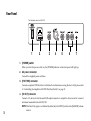
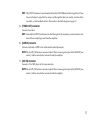
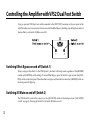
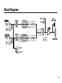
IMPORTANT SAFETY INSTRUCTIONS 2 •Read these instructions. •Keep these instructions. •Heed all warnings. •Follow all instructions. •Do not use this apparatus near water. •Mains powered apparatus shall not be exposed to dripping or splashing and that no objects filled with liquids, such as vases, shall be placed on the apparatus. •Clean only with dry cloth. •Do not block any ventilation openings. Install in accordance with the manufacturer’s instructions. •Do not install near any heat sources such as radiators, heat registers, stoves, or other apparatus (including amplifiers) that produce heat. •Do not defeat the safety purpose of the polarized or groundingtype plug. A polarized plug has two blades with one wider than the other. A grounding type plug has two blades and a third grounding prong. The wide blade or the third prong are provided for your safety. If the provided plug does not fit into your outlet, consult an electrician for replacement of the obsolete outlet. (for USA and Canada) •Protect the power cord from being walked on or pinched particularly at plugs, convenience receptacles, and the point where they exit from the apparatus. •Only use attachments/accessories specified by the manufacturer. •Unplug this apparatus during lightning storms or when unused for long periods of time. •Turning off the power switch does not completely isolate this product from the power line so remove the plug from the socket if not using it for extended periods of time. •Install this product near the wall socket and keep the power plug easily accessible. •WARNING—This apparatus shall be connected to a mains socket outlet with a protective earthing connection. •Refer all servicing to qualified service personnel. Servicing is required when the apparatus has been damaged in any way, such as power-supply cord or plug is damaged, liquid has been spilled or objects have fallen into the apparatus, the apparatus has been exposed to rain or moisture, does not operate normally, or has been dropped. •Do not install this equipment on the far position from wall outlet and/or convenience receptacle. •Do not install this equipment in a confined space such as a box for the conveyance or similar unit. •Excessive sound pressure from earphones and headphones can cause hearing loss. •Use only with the cart, stand, tripod, bracket, or table specified by the manufacturer, or sold with the apparatus. When a cart is used, use caution when moving the cart/apparatus combination to avoid injury from tip-over. The lightning flash with arrowhead symbol within an equilateral triangle, is intended to alert the user to the presence of uninsulated “dangerous voltage” within the product’s enclosure that may be of sufficient magnitude to constitute a risk of electric shock to persons. The exclamation point within an equilateral triangle is intended to alert the user to the presence of important operating and maintenance (servicing) instructions in the literature accompanying the product. CAUTION: Any changes or modifications not expressly approved by the party responsible for compliance may void the users authority to operate the equipment. Note: It is recommended that all audio cables, with the exception of the speaker lead, used to connect to the AGA70/150 is of a high quality, screened type. These should not exceed 10 metres in length. Always use a non-screened VOX approved speaker lead with the AGA70/150 Amplifier and extension cabinets. WARNING: Do not obstruct ventilation grilles and always ensure free movement of air around the amplifier! Notice regarding disposal (EU only) * All product names and company names are the trademarks or registered trademarks of their respective owners. A B C D E F ALWAYS use the supplied mains lead, if a replacement is required please contact your authorized VOX Dealer. DO NOT switch the amplifier on without a loudspeaker connected. ENSURE that any extension cabinets used are of the correct impedance. NEVER attempt to bypass the fuses or fit ones of the incorrect values. DO NOT attempt to remove the amplifier chassis, there are no user serviceable parts. Refer all servicing to qualified service personnel including replacement of fuses and valves. Servicing is required when the apparatus has been damaged in any way, such as when the power supply cord or plug is damaged, liquid has been spilled or objects have fallen into the apparatus, the apparatus has been exposed to rain or moisture, does not operate normally or has been dropped. When this “crossed-out wheeled bin” symbol is displayed on the product, owner’s manual, battery, or battery package, it signifies that when you wish to dispose of this product, manual, package or battery you must do so in an approved manner. Do not discard this product, manual, package or battery along with ordinary household waste. Disposing in the correct manner will prevent harm to human health and potential damage to the environment. Since the correct method of disposal will depend on the applicable laws and regulations in your locality, please contact your local administrative body for details. If the battery contains heavy metals in excess of the regulated amount, a chemical symbol is displayed below the “crossed-out wheeled bin” symbol on the battery or battery package. 3 Introduction Welcome! Thank you for purchasing the VOX AGA70/150 acoustic guitar amplifier. To help you get the most out of your new instrument, please read this manual carefully. Enjoy the wonderful world of the VOX AGA series amplifier! Features – Two channels - Tube Pre and Normal - each provides guitar and mic input. – The Tube Pre channel includes a 12AU7 (ECC82) tube, which offers the VOX signature tube tone. – The AGA70 amplifier features a built-in, VOX original full-range speaker. – The AGA150 amplifier employs a 2-way speaker with a VOX original woofer and tweeter to produce a pure acoustic sound. – A Color control, as well as Bass, Middle, and Treble controls, enable intuitive, flexible and even radical tone adjustments. Rotating a single control knob enables you to quickly achieve optimum settings for various playing techniques, from arpeggios to strumming chords. – The amplifier also features a high-quality reverb and chorus effects. You can easily change the tone of each channel by using the Reverb knob and the Chorus switch. – Line In/AUX In connectors are provided as external inputs that enable you to connect a keyboard or an MP3 player for practicing at home, for use as a portable PA system, or for a variety of other audio applications. – Connecting an optional VFS2 dual foot switch enables you to turn Bypass and All Mute on and off with your foot. 4 Setting Up Your Amplifier This section explains how to set up your amplifier. NOTE:This manual includes safety precautions and an explanation of the parts and functions of the amplifier. Please read this manual throughly. 1. Before turning the amplifire on set the [MASTER] volume control on the AGA70/150 to minimum. 2. Connect the supplied power cord to the AC power connector on the rear panel, then insert the plug on the other end of the power cord into an appropriate AC outlet. 3. If you are playing an acoustic musical instrument, such as a guitar with a pick-up, connect it to the [GUITAR] connector. If you are using a microphone, connect it to the [MIC] connector. NOTE:If the microphone requires phantom power, turn the [PHANTOM] switch on. If the microphone does not require phantom power, turn the [PHANTOM] switch off. 4. Turn on the power to the amplifier by setting the [POWER] switch to On. 5. Turn up the [MASTER] volume control slowly to adjust the volume level. 5 Part Names and Functions Front Panel 17 18 - L’illustration montre le AGA150. - ICEpower is a registered trademark of Bang & Olufsen ICEpower a/s. 1 2 3 4 5 6 7 8 9 10 11 12 13 14 15 16 1. NORMAL CH The Normal channel features a solid sound that will delive the natural acoustics of your instrument. 2. TUBE PRE (VALVE) CH The Tube Pre channel features a Vox signature warm sound due to a tube preamp that uses a 12AU7 valve. NOTE:It may take several seconds for the tube to warm up after the power is turned on. During this time, you may not hear any sound, but this is not a malfunction. 6 3. [GUITAR] connector Plug in your guitar (or other acoustic musical instrument featuring a pick-up) using a high-quality shielded cable. NOTE:If you plug in your instrument to this connector, the [MIC] connector on the same channel will be disabled. 4. [GAIN] switch Set the input gain to “LOW” or “HIGH” depending on the volume level of the musical instrument connected to the [GUITAR] or [MIC] connector. 5. [MIC] connector Connect your microphone to this balanced XLR connector. 6. [PHANTOM] switch Turn this switch on when you connect a condenser microphone that requires phantom power. When the phantom power is being supplied, the indicator above the switch lights up. NOTE:If the microphone does not require phantom power, turn the [PHANTOM] switch off. NOTE:Before you turn the [PHANTOM] switch on or off, be sure to set the [MASTER] volume control to minimum. Also, before you connect a microphone to the [MIC] connector, be sure to turn the [PHANTOM] switch off. 7. [VOLUME] control This control knob enables you to adjust the volume level of the musical instrument connected to the [GUITAR] or [MIC] connector. Use this control on each channel to adjust the level and balance between the Normal and Tube Pre channels. 7 8. [CLIP] indicator This indicator lights up if the volume level of the connected musical instrument is too high. Clipping could distort the sound and reduce the sound fidelity. To avoid clipping, use the [GAIN] switch and [VOLUME] control to adjust the volume level. 9. [BASS] control 10. [MIDDLE] control 11. [TREBLE] control These controls enable you to adjust the tone in the low, mid and high ranges respectively. NOTE:Turn each control clockwise to enhance the corresponding range. Please note that too much enhancement could cause feedback. 12. [COLOR] control This control enables you to adjust the tonal color to fit your playing style and situation. Turn the control counter-clockwise for a fat and sound, and turn it clockwise for a cleaner and “chimier” sound. 13. [REVERB] control This control enables you to adjust the reverb effect. Turn the knob clockwise for more reverb. 14. [CHORUS] switch This switch turns the chorus effect on and off. When the switch is turned on, the indicator above the switch lights up. 15. [MASTER] volume control This control enables you to adjust the overall volume level of the Normal and Tube Pre channels. NOTE:The [MASTER] volume control does not affect the signal level at the [DI OUT], [TUNER OUT], [AUX IN] or [LINE IN] connectors. 8 16. [ALL MUTE] switch Set this switch to On to mute the sound output from the amplifier. NOTE:This switch does not mute the sound output from the [DI OUT] or [TUNER OUT] connectors. HINT: Connect an optional VFS2 dual foot switch to the amplifier to control All Mute on and off with your foot. 17. [ANTI-FEEDBACK] control This control enables you to reduce the amount of feedback that is caused when the output from the amplifier is picked up via a guitar or microphone. Set the control knob so that the amount of feedback will be minimum. Turning the control knob clockwise will move the cut point to a higher frequency range. Turning the control knob counter-clockwise all the way will turn off the anti-feedback effect. Turn this control off if you hear no feedback. 18. [POWER] indicator The indicator lights up when the power to the unit is turned on. The [POWER] switch is located on the rear panel. 9 Rear Panel The Illustration shows the AGA150. 1 2 3 4 5 6 7 1. [POWER] switch When you turn this power switch on, the [POWER] indicator on the front panel will light up. 2. AC power connector Connect the supplied power cord here. 3. [FOOT SW] connector Connect an optional VFS2 dual foot switch here. For information on using the foot switch, please refer to “Controlling the Amplifier with VFS2 Dual Foot Switch” on page 12. 4. [DI OUT] connector Connect a PA device to this balanced XLR output connector to output the direct sound of a musical instrument connected to the AGA70/150. 10 NOTE:The Direct Out signal is not affected by either the [ALL MUTE] switch or the [MASTER] volume control. HINT: The [DI OUT] connector is positioned just before the [VOLUME] control in the signal flow. Therefore, it will output a signal that has not passed through the tube, tone control, reverb and chorus effects, or anti-feedback control. (Please refer to the block diagram on page 13.) 5. [TUNER OUT] connector Connect a tuner here. HINT: Since the [ALL MUTE] switch does not affect the signal at this connector, you can tune the instrument without outputting sound from the amplifier. 6. [LINE IN] connector Connect a keyboard or MTR to this unbalanced standard phone jack. NOTE:The AGA70/150 features a monaural output. When a stereo signal is input to the [LINE IN] connector, it will be converted to monaural inside the amplifier. 7. [AUX IN] connector Connect a CD or MP3 player to this stereo mini jack. NOTE:The AGA70/150 features a monaural output. When a stereo signal is input to the [LINE IN] connector, it will be converted to monaural inside the amplifier. 11 Controlling the Amplifier with VFS2 Dual Foot Switch Using an optional VFS2 dual foot switch connected to the [FOOT SW] connector on the rear panel of the AGA70 enables you to use your foot to turn on and off the Effect Bypass (disabling or enabling the reverb and chorus effects), and switch All Mute on and off. Switching Effect Bypass on and off (Switch 1) When you bypass the effects via the VFS2 Switch 1, all effects will be bypassed, regardless of the [REVERB] control and [CHORUS] switch settings. To cancel Effect Bypass, press the Switch 1 again or press the [CHORUS] switch on the front panel. When the effects are bypassed, the indicator above the [CHORUS] switch on the front panel will light up. Switching All Mute on and off (Switch 2) The VFS2 Switch 2 works in the same way as the [ALL MUTE] switch on the front panel (see “[ALL MUTE] switch” on page 9). Pressing the Switch 2 will switch All Mute on or off. 12 Block Diagram 13 Specifications I/Os: (NORMAL CH) GUITAR, MIC (TUBE PRE CH) GUITAR, MIC (Common) AUX IN, LINE IN, DI OUT, TUNER OUT, FOOT SW Phantom Power: +15V Effects: REVERB, CHORUS Output Power: AGA70; 70 watts RMS into 8 ohms AGA150; 150 watts RMS into 4 ohms Speaker: AGA70; VOX original (6.5 inch 8 ohm) full-range speaker x1 AGA150; VOX original (6.5 inch 4 ohm) woofer x1 VOX original (1 inch 4 ohm) dome tweeter x1 Power Source: AC, local voltage Power Consumption: AGA70; 73W AGA150; 48W Dimensions (W x D x H): AGA70; 323 x 262 x 331mm / 12.72 x 10.31 x 13.03inches AGA150; 373 x 362 x 331mm / 14.68 x 14.25 x 13.03inches Weight: AGA70; 10.1kg / 22.3lbs AGA150; 12.2kg / 26.9lbs Accessory: Power cord Optional Item: VFS2 Dual foot switch, VST-01 Speaker stand (AGA150 only) * Do not use any other speaker stand. * Before using the VST-01 Speaker Stand, be sure to read "Using the Speaker Stand." * Specifications and appearance are subject to change without notice for improvement. 14 IMPORTANT NOTICE TO CONSUMERS This product has been manufactured according to strict specifications and voltage requirements that are applicable in the country in which it is intended that this product should be used. If you have purchased this product via the internet, through mail order, and/or via a telephone sale, you must verify that this product is intended to be used in the country in which you reside. WARNING: Use of this product in any country other than that for which it is intended could be dangerous and could invalidate the manufacturer’s or distributor’s warranty. Please also retain your receipt as proof of purchase otherwise your product may be disqualified from the manufacturer’s or distributor’s warranty. 2009 VOX AMPLIFICATION LTD.