1
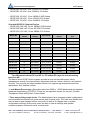
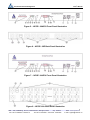
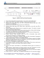
SQ Remote Power Management
User’s Manual
User's Manual
For SP/NP Series Remote Power Management
SP/NP 02, SP/NP 08, SP/NP 16 and SP/NP 20
V1.0
Shanghai Qianjin Electronic Equipment Co.,Ltd
____________________________________________________________1
Addr:A/4F, 2# Building , No.401, Caobao Road , Shanghai ,China
Zip:200233
Fax:86-21-64858301 - 62401979
Tel:86-21-54973555 – 34140103 - 64957666
Web:www.sq-catv.com
E-mail:[email protected]
SQ Remote Power Management
User’s Manual
Copyright Notice
Copyright © 2008 by Shanghai Qianjin Electronic Equipment Co.,Ltd. The material
discussed in this manual is the proprietary property of Shanghai Qianjin Electronic
Equipment Co.,Ltd, AII retains all rights to reproduction and distribution of this document.
FCC Warning
The Federal Communications Commission has set limits for emitted radio interference. The
Shanghai Qianjin Networks systems are constructed with this electromagnetic interference
(EMI) limitation in mind. The systems are classified under FCC Regulations as a Class A and
Class B device. A Class A device may be used in commercial environments and not in
residential areas, while a Class B device may be used in commercial environments
residential areas. The “SP/NP Series “ series devices has been tested and shown to comply
with the following FCC rule: Part 15 Subpart Jand ICES-003.
FCC Declaration Compliance
47CFR Part 15 regulation & ANSI C63.4 Class B
CE Safety Standards Compliance
“SP/NP Series” Series products have been tested and found to be accordance with the
following listed test requirements:
EN55022:2006; EN6100-3-2:2006; EN6100-3-36:1995+A1:2001+A2:2005;
EN55024:1998+A1:2001+A2:2003;
EN60950-1:2006;
Warranty Information:
The warranty period on this product (parts and labor) is one (1) year from the date of
purchase. Please contact Shanghai Qianjin Electronic Equipment Co.,Ltd at 86-21-5497
3222 or visit our website at www.sq-catv.com for information regarding repairs and/or returns.
A return authorization number is required for all repairs/returns.
See Appendix A for more information.
Changes:
The material in this guide is for information only and is subject to change without notice.
Shanghai Qianjin Electronic Equipment Co.,Ltd reserves the rights to make changes in the
product design without reservation and without notification to its users.
SQ-Shanghai Qianjin Electronic Equipment Co.,Ltd.
Add: A/4F, Building No.2,No.401,Caobao Road Shanghai China
Tel: 0086-21-54973222 54973555 64957666
Fax: 0086-21-64858301
____________________________________________________________2
Addr:A/4F, 2# Building , No.401, Caobao Road , Shanghai ,China
Zip:200233
Fax:86-21-64858301 - 62401979
Tel:86-21-54973555 – 34140103 - 64957666
Web:www.sq-catv.com
E-mail:[email protected]
SQ Remote Power Management
User’s Manual
Table of Contents
1 System Description…….....................................................................................................................5
1.1 Products Comparison Chart: ...............................................................................................................5
1.2 What You Can Do With the System.....................................................................................................7
1.3 Front and Back Panel...................................................…………….….................................................8
2 Important Safety Precautions For Hardware Installation…………………….................................12
2.1 Safety Precautions .............................................................................................................................12
2.2 Battery Replacement..........................................................................................................................12
3 Access To the System......................................................................................................................13
3.1 Factory Default Settings…..................................................................................................................13
3.2 User Privileges and Port Reservations…. ..........................................................................................14
3.3 Local Master Port Access..:................................................................................................................ 14
3.4 External Modem Access. ....................................................................................................................14
3.5 Telnet Access......................................................................................................................................15
3.6 WEB Access…:.................................................….............................................................................. 16
3.7 Email Access…..:.................................................................................................................................17
3.8 SNMP Information……….. ..................………………………................................................................18
3.9 Autoping and Power Reboot………......................…............................................................................19
4 Using Control Command………….....................................................................................................20
5 Using Configuration MENU………….................................................................................................22
5.1 Starting Configuration Menu.……….....................................................................................................22
5.2 Viewing and Changing Operation Status .............................................................................................22
5.3 Power Outlet Setup Menu.....................................................................................................................23
5.4 Power Outlet Timer Setup Menu ..........................................................................................................25
5.5 User Account Setup Menu.....................................................................................................................27
5.6 System Access Setup Menu...........…………………..…………………..........................….................... 28
5.7 Serial Port Setup Menu .........................................................................................................................30
5.8 TCP/IP Network Configuration Menu ....................................................................................................31
5.9 More About TCP/IP Network Configuration...........................................................................................34
5.10 More about Emailing Access ………....................................................................................................35
5.10.1Sending Control command to the system ...........................................................................................35
Appendix A Warranty Information ...........................................................................................................36
Appendix B RS-232 To RJ45 Conversion Cables...................................................................................38
History…………………………………………………....................................................................................39
____________________________________________________________3
Addr:A/4F, 2# Building , No.401, Caobao Road , Shanghai ,China
Zip:200233
Fax:86-21-64858301 - 62401979
Tel:86-21-54973555 – 34140103 - 64957666
Web:www.sq-catv.com
E-mail:[email protected]
SQ Remote Power Management
User’s Manual
Table of Figures
Figure
1 - Product Comparison Chart .................................................................................................5
Figure
2 - Illustration of Typical Application.......................................................................................8
Figure
3 - NP/SP-02A/E/U Front Panel Illustration ...........................................................................8
Figure
4 - NP/SP-02E Back Panel Illustration ..................................................................................8
Figure
5 - NP/SP- 08A/E/U Front Panel Illustration ..........................................................................9
Figure
6 - NP/SP- 08E Back Panel Illustration ..................................................................................9
Figure
7 - NP/SP-16A/E/U Front Panel Illustration..................................................................….......9
Figure
8 - NP/SP-16A Back Panel Illustration....................................................................................9
Figure
9 - NP/SP- 20U Front Panel Illustration.................................................................................10
Figure
10 - System Startup Screen........................................................................................….......13
Figure
11 - Telnet Session Startup screen.............................................................................….......15
Figure
12 - Web Access Startup Page (NP-08)................................................................................16
Figure
13 - Web Access Login Entry Table .....................................................................................17
Figure
14 - Email Access - Sending Command from Hotmail Web Site ..........................................17
Figure
15 - List of MIB object............................................................................................................18
Figure
16 - Control Command Help Menu........................................................................................21
Figure
17 - System Operation Static (Web Page) ..............................................................................22
Figure
18 - Power Outlet Setup Menu (Web Page) ............................................................................23
Figure
19 - List of Power Outlet Status (Terminal Screen)...............................................................24
Figure
20 - Power Outlet Timer Setup Menu (Web Page)...................................................................25
Figure
21 - Definitions of Timer Parameters ......................................................................................26
Figure
22 - User Account Management Menu (Web Page) ................................................................27
Figure
23 - System Access Control Menu (Web Page).......................................................................28
Figure
24 - Serial Port Setup Menu (Web Page).................................................................................30
Figure
25 - TCP/IP Network Configuration Menu (Web Page) ........................................................... 31
____________________________________________________________4
Addr:A/4F, 2# Building , No.401, Caobao Road , Shanghai ,China
Zip:200233
Fax:86-21-64858301 - 62401979
Tel:86-21-54973555 – 34140103 - 64957666
Web:www.sq-catv.com
E-mail:[email protected]
SQ Remote Power Management
User’s Manual
1 System Description
1.1 Products Comparison Chart:
Item
Enter Plug
Supply Plug
SP/NP- 02 Series
SP/NP- 08 Series
SP/NP- 16 Series
SP/NP- 20 Series
1
1-2
2
1-2
NEMA5-15P NEMA5-20P CEE7/7 BS1363 IEC60309 NEMA L6-20P NEMA L6-30P
IEC60320-C14
IEC60320-C14
IEC60320-C14
IEC60320-C14
IEC60320-C20
IEC60320-C20
IEC60320-C20
IEC60320-C20
(2)NEMA5-15
(8)NEMA5-15
(16)NEMA5-15
(20)NEMA5-15
(2)NEMA5-20R
(8)NEMA5-20R
(16)NEMA5-20R
(20)NEMA5-20R
(2) IEC60320-C13
(8)IEC60320-C13
(16)IEC60320-C13
(20)IEC60320-C13
Input current
15-20 Amp
15-40 Amp
30-40 Amp
15-40 Amp
Input Voltage
100-240 VAC
100-240 VAC
100-240 VAC
100-240 VAC
Equipment End
Outlets
Chassis
Console Port
W: 6.0" (150mm)
W:19"
D: 6.7" (170mm)
H: 1.75" (44mm)
Display
Operating
Temperature
Storage
Temperature
Humidity
W: 19" (482mm)
W: 2.0"
(50mm)
D:7.0" (180mm)
D:
7" (180mm)
D: 2.75" (70mm)
H:1.75"(44mm)
H: 3.5" (88mm)
H: 55" (1400mm)
baud rate:115200; 8data bits; no parity;1 stop bit,no hardware handshaking
10/100 Base-T, support AUTO-MDIX
Ethernet
Network
protocol
(482mm)
ICMP, IP, TCP/UDP, DHCP, Telnet, DNS, POP3/SMTP, SNMP, HTTP, HTTPS and SSH/SSL
16LEDs
24LEDs
26LEDs
Three Digit Display
Three Digit Display
Three Digit Display
6LEDs
32oF - 122oF ( 0℃ - 50℃ )
-20oF - 140oF ( -29℃ - 60℃ )
10-90% RH
Figure 1 – Product Comparison Chart
Model Numbers
The NP/SP series includes horizontal/vertical 2/8/16/20 outlet and 120/240 VAC models to
accommodate a variety of data center equipment racks and power distribution needs.
Two outlet NP/SP Series:
• NP/SP-02A 120 VAC, 2 ea. NEMA 5-20R Outlets
• NP/SP-02E 240 VAC, 2 ea. IEC320-C13 Outlets
• NP/SP-02U 120 VAC, 2 ea. NEMA 5-15 Outlets
Eight and sixteen outlet NP/SP (Horizontal) Series:
• NP/SP08A 120 VAC, 8 ea. NEMA 5-20R Outlets
____________________________________________________________5
Addr:A/4F, 2# Building , No.401, Caobao Road , Shanghai ,China
Zip:200233
Fax:86-21-64858301 - 62401979
Tel:86-21-54973555 – 34140103 - 64957666
Web:www.sq-catv.com
E-mail:[email protected]
SQ Remote Power Management
User’s Manual
• NP/SP08E 240 VAC, 8 ea. IEC320-C13 Outlets
• NP/SP08U 120 VAC, 8 ea. NEMA 5-15 Outlets
• NP/SP16A 120 VAC, 16 ea. NEMA 5-20R Outlets
• NP/SP16E 240 VAC, 16 ea. IEC320-C13 Outlets
• NP/SP16U 120 VAC, 16 ea. NEMA 5-15 Outlets
20-outlet NP/SP-20 (Vertical) Series:
• NP/SP-20A 120 VAC, 20 ea. NEMA 5-20R Outlets
• NP/SP-20E 240 VAC, 20 ea. IEC320-C13 Outlets
• NP/SP-20U 120 VAC, 20 ea. NEMA 5-15 Outlets
Total
Outlets
Input
Voltage
Input Feeds
Max.Load per
Group
Max.Load per
Unit
NP/SP-02A
2
100-120VAC
(1 ea.) 20 Amp
20 Amps
20 Amps
NP/SP-02E
2
100-240VAC
(1 ea.) 16 Amp
16 Amps
16 Amps
NP/SP-02U
2
100-120VAC
(1 ea.) 15 Amp
15 Amps
15 Amps
NP/SP-08A
8
100-120VAC
(1/2 ea.) 20 Amp
20 Amps
40 Amps
NP/SP-08E
8
100-240VAC
(1/2 ea.) 16 Amp
16 Amps
32 Amps
NP/SP-08U
8
100-120VAC
(1/2 ea.) 15 Amp
15 Amps
30 Amps
NP/SP-16A
16
100-120VAC
(2 ea.) 20 Amp
20 Amps
40 Amps
NP/SP-16E
16
100-240VAC
(2 ea.) 16 Amp
16 Amps
32 Amps
NP/SP-16U
16
100-120VAC
(2 ea.) 15 Amp
15 Amps
30 Amps
NP/SP-20A
20
100-120VAC
(1/2 ea.) 20 Amp
20 Amps
40 Amps
NP/SP-20E
20
100-240VAC
(1/2 ea.) 16 Amp
16 Amps
32 Amps
NP/SP-20U
20
100-120VAC
(1/2 ea.) 15 Amp
15 Amps
30 Amps
Model No.
The difference between SP and NP is: SP added SSL layer for web accessing
based on NP.
The above listed SP/NP Series systems provide secure and versatile power reboot
management access for communication equipment such as routers, switches, and network
devices. They are also the ideal assistant devices for engineering development and test
applications. Key features include:
• Local Master Port access: offers data rates from 2400 to 115200 bits/second and optional
hardware handshaking (CTS/RTS). There are two operation modes for the port: Console
Transparent Mode and System Control Mode.
• Three user privilege login levels: The Administration level manages system configuration
and unconditional access to all power outlets and all serial ports. The User level allows each
user to reserve and manage his/her own ports, as well as to change most of system
configuration settings. Anonymous users are able to view all settings and operate
unreserved power outlets and serial console ports.
____________________________________________________________6
Addr:A/4F, 2# Building , No.401, Caobao Road , Shanghai ,China
Zip:200233
Fax:86-21-64858301 - 62401979
Tel:86-21-54973555 – 34140103 - 64957666
Web:www.sq-catv.com
E-mail:[email protected]
SQ Remote Power Management
User’s Manual
• User name and password for each port: Each port is user name and password
protected.
• Line commands or menu configuration controls: Menu table operation offers
user-friendly operation methods that are used for changing system configurations, viewing
run time statuses, and issuing controls. Line commands provide quick and easy operations.
• Telnet access: Remote access the system over a TCP/IP network for configuration and
control of the systems.
• Out of band Modem access interfacing: Control and configure the system via a
telephone line. Optional custom Modem AT command string to the Modem.
• HTTP web access: Embedded web server provides secured user name and password
authentication. The operations are easy and friendly, utilizing tables and graphical icons.
Download SNMP MIB files for convenience, or view an online help manual.
• SNMP MIB capability: An SNMP (Simple Network Management Protocol) agent is
integrated in the system for an exchange of management information between the system
and network devices.
• POP/SMTP Emailing with SMTP Authentication capability: A user can send control
commands such as reboot power outlet via emails. Command execution reports are replied
for each command email received. SMTP user name and password are protected through
authentication process.
• SNMP Trap for sending logging message: The Trap is used to asynchronously report
events to the NMS. It forwards power reboot command execution information to the remote
Trap logging receiver.
1.2 What you can do with the system:
• Remote equipment power source management over TCP/IP networks, including
rebooting user equipment, and permanently turning on/off user power source. Schedule
power reboots or power source on/off events monthly, weekly, daily or at any time an
application requires.
Reboot power source to equipment when a network connection is lost.
• Monitoring AC Power Consumptions and sending warning messages when the
aggregated AC draw from a system is crossed predefined threshold.
• Remote control anywhere by emailing. Via emails, you are able to manage the systems
or user communication equipment power sources when LAN access is impossible. Via
emails, you can send user data to the NP control commands such as rebooting user power
source.
Reply emails are sent after the system intercepts incoming emails so that you are informed
with the operation status.
____________________________________________________________7
Addr:A/4F, 2# Building , No.401, Caobao Road , Shanghai ,China
Zip:200233
Fax:86-21-64858301 - 62401979
Tel:86-21-54973555 – 34140103 - 64957666
Web:www.sq-catv.com
E-mail:[email protected]
SQ Remote Power Management
User’s Manual
• AutoPing and reboot user equipment. Connect your system to a power outlet and assign
the system network IP address or URL. The NP system will ping the user equipment
periodically (in every 15 seconds). If the user equipment stops responding the ping request,
the equipment will be power rebooted.
• Scheduling AC outlet power cycling periodically or per weekly planner. Each outlet can be
programmed with it’s own timer.
Figure 2 - Illustration of Typical Application
1.3 Front and Back Panel:
Figure 3 – NP/SP-02A/E/U Front Panel Illustration
Figure 4 – NP/SP-02E Back Panel Illustration
____________________________________________________________8
Addr:A/4F, 2# Building , No.401, Caobao Road , Shanghai ,China
Zip:200233
Fax:86-21-64858301 - 62401979
Tel:86-21-54973555 – 34140103 - 64957666
Web:www.sq-catv.com
E-mail:[email protected]
SQ Remote Power Management
User’s Manual
Figure 5 – NP/SP- 08A/E/U Front Panel Illustration
Figure 6 – NP/SP- 08E Back Panel Illustration
Figure 7 – NP/SP-16A/E/U Front Panel Illustration
Figure 8 – NP/SP-16A Back Panel Illustration
____________________________________________________________9
Addr:A/4F, 2# Building , No.401, Caobao Road , Shanghai ,China
Zip:200233
Fax:86-21-64858301 - 62401979
Tel:86-21-54973555 – 34140103 - 64957666
Web:www.sq-catv.com
E-mail:[email protected]
SQ Remote Power Management
User’s Manual
Figure 9 – NP/SP- 20U Front Panel Illustration
1) Power Outlet status LED: Visual indication of user power outlet On/Off status.
2) System power On/Off status LED: Indication of system power On/Off status.
3) Ethernet Link status LED: When the LED is illuminated, Ethernet port and a LAN
connection are established.
4) Ethernet speed status LED: Ethernet port have 100M status.
5) Ethernet Active data status LED: When there is data traffic on the LAN, the LED is
illuminated.
6) Factory Upgrade switch: Allow the user to upgrade the system. The switch is located
behind the small front panel opening.
7) Factory Default Reset switch: Allow a user to reset the system to factory default settings.
The switch is located behind the small front panel opening.
8) A and B Selection LED: When the LED is illuminated, For Circuits A or B Amps which
measurement will appear on the Digital Displays.
9 ) Display Selection Amps Indicators: When the LED is illuminated, Amps which
measurement will appear on the Digital Displays.
10)Display Selection Temperature Indicators: When the LED is illuminated, Temperature
which measurement will appear on the Digital Displays.
11)Display Selection Button : Each time the Display Selection Button is pressed, the Digital
Displays will toggle Between Amps and Temperature, and the LED indicators will light to
show which measurement is currently selected.
12)Sensor Port: Temperature is measured port (e.g. PT100).
13)Local Master Port (DCE, 9 pin DB, female, or RJ-45 socket): This is also a service port
for the user to configure and change system operation settings.
14)USB Port:
15)Ethernet Port (RJ45, 10/100 Base-T): 10/100 Based-T Ethernet port for connection to
LAN.
18)Digital Displays: Digital Displays will toggle between Amps and Temperature, and the
LED indicators will light to show which measurement is currently selected.
20)Power Circuit A - Power Inlet: An NEMA5-15P/IEC320-C14 AC inlet which supplies
power (08 Series 1-4 outlets; 16 Series 1-8 outlets).
21)Power Circuit B - Power Inlet: An NEMA5-15P/IEC320-C14 AC inlet which supplies
____________________________________________________________10
Addr:A/4F, 2# Building , No.401, Caobao Road , Shanghai ,China
Zip:200233
Fax:86-21-64858301 - 62401979
Tel:86-21-54973555 – 34140103 - 64957666
Web:www.sq-catv.com
E-mail:[email protected]
SQ Remote Power Management
User’s Manual
power (08 Series 5-8 outlets; 16 Series 9-16 outlets).
22)Power Breaker: System turn power on/off.
23)Power Circuit A - Switched Outlets: AC Outlets that can be switched On, Off or rebooted
in response.
24)Power Circuit B - Switched Outlets: AC Outlets that can be switched On, Off or rebooted
in response
Caution:
Sensor interface can be connected only with (e.g. PT100) (Do not connect a
telephone line and so on).
____________________________________________________________11
Addr:A/4F, 2# Building , No.401, Caobao Road , Shanghai ,China
Zip:200233
Fax:86-21-64858301 - 62401979
Tel:86-21-54973555 – 34140103 - 64957666
Web:www.sq-catv.com
E-mail:[email protected]
SQ Remote Power Management
User’s Manual
2 Important Safety Precautions for Hardware Installation
2.1 Safety Precautions
It is important that you read this section before attempting any of the hardware installation
and maintenance procedures in this guide.
The following instructions are important for your safety and for the functioning of the unit.
Read the instructions carefully before attempting the installation
WARNING!
To reduce the risk of fire or electrical shock, never remove the cover of the unit. No
user serviceable parts inside. Repair should be done by authorized service personnel
only.
The unit should be installed in indoor with ambient temperature and sufficient airflow.
WARNING!
Ensure that the hardware you are working with is disconnected from the power supply during
installation. This means that the unit’s power cable and network cables must remain
disconnected until you are instructed to make the connections. Follow the instructions in the
procedures carefully.
This equipment is disconnected from the power supply by removing the power cord(s) from
the power outlet. It is therefore important to locate the unit close to a power outlet that is
easily accessible.
WARNING!
When connecting a hardware unit to a power supply, for your safety you must always
connect it to a grounded wall outlet.
2.2 Battery Replacement
A 3.0V Lithium recharging battery is installed in the unit for internal Real-Time Clock and
system data retention. The battery should last at least recharging 1000,000 times. If the
battery needs to be replaced, please ask authorized service personnel to do so.
____________________________________________________________12
Addr:A/4F, 2# Building , No.401, Caobao Road , Shanghai ,China
Zip:200233
Fax:86-21-64858301 - 62401979
Tel:86-21-54973555 – 34140103 - 64957666
Web:www.sq-catv.com
E-mail:[email protected]
SQ Remote Power Management
User’s Manual
3 Access to the System
3.1 Factory Default Settings:
The system is shipped with Factory Default settings. The default settings for the Local
Master serial port are: 115200, 8 data bits, no parity, 1 stop bit, and no hardware
handshaking (Flow Control).
The default Ethernet setting are: IP:192.168.1.100, GateWay:192.168.1.1, NetMask:
255.255.255.0
The default Administrator’s login name “admin” and the default password is “admin” and
user’s login name “user” and the default password is “user”. All existing user accounts are
erased if the system is recovered to the default settings. The default SNMP Community
string for public, private and Trap access is “public”.
There are two ways to restore the system to the Factory Default settings. The first method is
to press a push-button switch located on the front panel for 1 second. The second method is
to select "Set Default Factorys" from the Main Menu. The Main Menu can be viewed by
running a terminal emulation program such as Window’s Hyper Terminal.
Upon the system startup, the terminal screen displays the following screen, as shown in the
Figure 6.
.
If you do not see the screen as shown in the Figure 6, it is likely that the system is not in the
default state. Otherwise, your connection to the Local Master port is established.
Figure 10 - System Startup Screen
____________________________________________________________13
Addr:A/4F, 2# Building , No.401, Caobao Road , Shanghai ,China
Zip:200233
Fax:86-21-64858301 - 62401979
Tel:86-21-54973555 – 34140103 - 64957666
Web:www.sq-catv.com
E-mail:[email protected]
SQ Remote Power Management
User’s Manual
3.2 User Privileges and Port Reservations:
All user levels, including anonymous (visitor), are able to access the system via a serial
connection from your work station to the Local Master port, or via a Telnet session from your
work station.
• Administration Login:
There is 8 Administration account at most on the system. The default name is “admin” and
default password is also “admin”. The default name and password may be changed. If you
login at Administration level, you are able to remove or change existing user accounts, take
over power outlets or user serial console ports and change system settings.
• User Login:
At user login level, you are able to reserve power or console ports for your applications if
they are “open”, as well as make system configuration changes. At this login level, you are
not able to change power outlet operation status for other reserved power outlets.
• Guest(Visitor) Access:
At user guest level (as an visitor user), you are only able to view the system configuration
settings and operate unreserved power outlets.
3.3 Local Master Port Access:
To access and configure the system from the master port, you need to connect a RS232 port
from your work station to the Local Master Serial Port. Then run a terminal emulation
program (such as Window’s Hyper Terminal) on your computer.
1) Connect the system’s Local Master Port (DCE) with a straight DB-9 type cable, if your
work station is equipped with a DTE part.
2) Connect the system’s Ethernet port to your LAN, if you intend to use the network port.
3) Turn the system power on.
4) At the terminal emulation program, type the “help” for help information.
5) The system has DHCP enabled, as a default setting. Network connectivity parameters
displayed at the startup screen. If the system does not get a DHCP offer,the system falls
back to default static network settings. You can alter the default network settings to fit your
need.
6) Use the command “ping” to verify your connection. If a network connection is established,
you are able to use Telnet, Web Browsing, Emailing and SNMP.
3.4 External Modem Access:
With this access method, an RS232 port on an external Modem device is connected to the
Local Master Port. Typically, a Modem device is equipped with a DCE (Data Communication
Equipment) terminal connector. Since the system’s Local Master Port and Modem device
ports are not complementary (both are DCE ports); you need to use a NULL Modem cable
with both male connectors.
____________________________________________________________14
Addr:A/4F, 2# Building , No.401, Caobao Road , Shanghai ,China
Zip:200233
Fax:86-21-64858301 - 62401979
Tel:86-21-54973555 – 34140103 - 64957666
Web:www.sq-catv.com
E-mail:[email protected]
SQ Remote Power Management
User’s Manual
3.5 Telnet Access:
Operation of on a Telnet terminal is almost identical to the access method via Local Master
Serial Port. You need to make sure that Telnet access is enabled, as a default setting. If the
access is not enabled, please refer to Section “Using Configuration Menu” to change the
setting.
Before you start the Telnet application, you need to obtain the actual IP address for the
system. The system displays network connectivity information at system startup terminal
when your workstation is connected to the system’s Local Master Serial Port. Please refer to
“TCP/IP Network Configuration” section of this document for information on how to setup the
network parameters.
Once the network connection is established, at your workstation prompt, you need to enter:
telnet ip_addr
The telnet terminal screen will display the following message once it starts, shown in Figure 8.
You need to set a Telnet session on your workstation to Local Echo Off mode.
Telnet session permits an anonymous user who may only to view the system settings and
operate unreserved power outlets and user serial console ports. Please refer to section 2.2
“User privileges and Port Reservations” for further information.
• There are 8 Telnet session at most may be active at the time.
• A Telnet session remains active for 10 minutes if it is in idle state.
• Telnet access methods can be enabled or disabled using the System Access Setup Menu.
• To terminate an active Telnet session, use the command “exit” at the terminal.
Figure 11 - Telnet Session Startup screen
____________________________________________________________15
Addr:A/4F, 2# Building , No.401, Caobao Road , Shanghai ,China
Zip:200233
Fax:86-21-64858301 - 62401979
Tel:86-21-54973555 – 34140103 - 64957666
Web:www.sq-catv.com
E-mail:[email protected]
SQ Remote Power Management
User’s Manual
3.6 Web Access:
You need to obtain the system IP address before starting web access to the system. Please
refer to the Telnet Access section for methods to get the system IP address. You also need
to make sure that web access is enabled, as a default setting. If the access is not enabled,
please refer to Section “Using Configuration Menu” to change the setting. Start a Web
browsing application program such as Window’s Explorer and enter “http://ip_address“(for
NP serial) or “https://ip_address“(for SP serial) in the address field.
You must have an account on the system in order to access the system via this method.
Without a valid account, you are only able to view the following web page and get a copy of
the Help text message.
Figure 12 - Web Access Startup Page (NP-08)
Upon clicking the Login button, a secured login table is displayed at you work station, shown
as in the Figure 10. Factory default setting for user name is “admin”. The default password is
“admin”.
____________________________________________________________16
Addr:A/4F, 2# Building , No.401, Caobao Road , Shanghai ,China
Zip:200233
Fax:86-21-64858301 - 62401979
Tel:86-21-54973555 – 34140103 - 64957666
Web:www.sq-catv.com
E-mail:[email protected]
SQ Remote Power Management
User’s Manual
Figure 13 - Web Access Login Entry Table
3.7 Email Access:
To establish this access method, the system’s network connection is already established.
With the email access method, you are able to execute the NP system controlling commands.
The NP system periodically checks incoming mails from a designated POP mail server. The
system sends a reply email with command process status if an email is intercepted. See
Section 4.4 for more information about how to setup email accounts.
Figure 14 - Email Access - Sending Command from Hotmail Web Site
____________________________________________________________17
Addr:A/4F, 2# Building , No.401, Caobao Road , Shanghai ,China
Zip:200233
Fax:86-21-64858301 - 62401979
Tel:86-21-54973555 – 34140103 - 64957666
Web:www.sq-catv.com
E-mail:[email protected]
SQ Remote Power Management
User’s Manual
3.8 SNMP Information:
Applications such as an NMS (Network Management System) or an SNMP browser can
exchange information with the NP systems. SNMP is disabled with the default setting.
The information managed by an SNMP daemon on the system can be obtained using SNMP
requests from a remote work station. An SNMP Get/Get Next request fetches the value of a
single variable or a set of variables. An SNMP Set request modifies the value of a variable.
You need to know the name of a variable before you can fetch or modify a variable's value. A
variable’s symbolic name is mapped to a numeric name, which is referred as OID.
The MIB (Management Information Base) is a text file describing the internal objects the
SNMP agent can display, monitor, and/or modify. Each MIB object is the system variable that
has name and an OID, as shown in Figure 12. You need the MIB file to properly configure
the SNMP client ("manager") for server monitoring. To get a copy of the MIB file, please use
a web browser to access the NP systems. Open the TCP/IP Network Configuration Menu
and then click the button “Get SNMP MIB File” to download the MIB file that is stored in the
system’s memory.
Enterprise OID: 1.3.6.1.4.1. 32287
Definition
OID
devName
.1.1
devType
.1.2
sysCurrentA
.1.3
sysCurrentB
.1.4
sysTemp
.1.5
Returned message
The system name or site name. Read only.
The system model type. Read only.
First AC current monitoring reading. For a system equipped
with single power cord, this the valid current reading. For
dual power corded system, this is the first part of the AC
current reading. Read only.
For dual power corded system, this is the AC current
reading for the second power inlet (or power cord). Read
only.
The system temperature, this is only available
when the temperature sensor is installed. Read
only.
Figure 15 - List of MIB object
____________________________________________________________18
Addr:A/4F, 2# Building , No.401, Caobao Road , Shanghai ,China
Zip:200233
Fax:86-21-64858301 - 62401979
Tel:86-21-54973555 – 34140103 - 64957666
Web:www.sq-catv.com
E-mail:[email protected]
SQ Remote Power Management
User’s Manual
3.9 AutoPing and Power Reboot:
Each power outlet has optional settings that a NP system uses to ping network equipment.
The pinged equipment is attached to a specific power outlet. It reboots user equipment
power source if a network connection is not detected any more. However, user equipment
never gets power reboot if the equipment never replies ping reply to a NP system.
A power outlet has the optional settings (Power Outlet Setup Menu) that specify the
destination IP address that the system will ping periodically, and maximum network
downtime allowed. In addition, to avoid unwanted reboots, a NP system also pings the
gateway IP address (as default) to make sure a NP system has a network connection that is
still active. Otherwise, AutoPing will be in off mode if a NP system lost network connection.
To change the default gateway IP address as ping destination, use TCP/IP Configuration
Menu to enter your desired destination address.
____________________________________________________________19
Addr:A/4F, 2# Building , No.401, Caobao Road , Shanghai ,China
Zip:200233
Fax:86-21-64858301 - 62401979
Tel:86-21-54973555 – 34140103 - 64957666
Web:www.sq-catv.com
E-mail:[email protected]
SQ Remote Power Management
User’s Manual
4 Using Control Command
A NP system provides command line options for viewing or changing system configuration
and operation status. In addition, by using the control command option, users are able to
create script files for automation of equipment test and control.
Control commands are applicable to the connections between your work station and Local
Master Serial Port or a Telnet session.
Some of the control commands are also applicable to emails. See related sections for more
detailed information about how to setup email accounts.
Once the system starts or a Telnet session is open, you are ready to send control command
to the system. Type command “help” to have a complete list of available commands, as
shown in Figure 13.
All login levels including anonymous users are able to use the command line option.
However, the actual command executions are based on your login level. For example, if you
are an anonymous user, you are not able to reserve or un-reserve serial console ports or
power outlets. If you login at Administration level, you are able to operate any serial ports
and power outlets, reserve or unreserved any ports or outlets even if they are reserved by
other users. See Section 2.2 for a complete description of user privileges.
____________________________________________________________20
Addr:A/4F, 2# Building , No.401, Caobao Road , Shanghai ,China
Zip:200233
Fax:86-21-64858301 - 62401979
Tel:86-21-54973555 – 34140103 - 64957666
Web:www.sq-catv.com
E-mail:[email protected]
SQ Remote Power Management
User’s Manual
************************************************************
*
*
*
*
*
Help Menu
*
*
*
*
*
************************************************************
**NOTE : command marked with * need user permission
**NOTE : command marked with # need admin permission
login
login
logout
logout
whoami
who am i?
#ul
show userlist
ver
show the hw/sw version
date
print current date
time
print current time
temp
read temperature sensor
cura
read current sensor a
curb
read current sensor b
#ssn 0x12345678
set serial num
sshow
Displays console ports configuration status
#reinit
set default factorys (need reboot)
pshow
Displays power outlet status
ptshow
Displays power outlet timer information.
*pset n v
Sets power outlet #n to v(value 1-on, 0-off)
*ps v
Sets all power outlets to v(value 1-on, 0-off)
*prb n
Reboot power outlet #n
*prsv n
Reserve power outlet #n for current user
*punrsv n
Unreserve power outlet #n for current user
mac
print the mac addr
ping 10.10.26.236
ping an ip address
acl 0/1
Disable/Enable ACL
*aclset id type mask
id(1-6), type(0=Not Care/1=Permit/2=Block), mask(ip)
smtp lalalalala
send an email
getmail
fetch mail from pop3 server
#web 0/1
disable/enable web access
#pop3 0/1
disable/enable pop3 access
#telnet 0/1/2
config telnet access to disable/login_only/enable
dns www.sina.com.cn
domain name server
*dhcp
do dhcp routin
*ip 10.10.26.123
set network static ip
*gw 10.10.26.1
set network gateway
*netmask 255.255.255.0 set network netmask
*ifconfig auto/dhcp/static
do network interface config
nwshow
display network status
help
show help messages
*!
Repeat the last command
>
Figure 16 - Control Command Help Menu
____________________________________________________________21
Addr:A/4F, 2# Building , No.401, Caobao Road , Shanghai ,China
Zip:200233
Fax:86-21-64858301 - 62401979
Tel:86-21-54973555 – 34140103 - 64957666
Web:www.sq-catv.com
E-mail:[email protected]
SQ Remote Power Management
User’s Manual
5 Using Configuration Menu
5.1 Starting Configuration Menu:
There are four ways to start the Configuration Menu:
1) Local Master Port access method. Run a terminal program from a work station via serial
connections between a serial port from your work station and the Local Master Port of the
system.
2) External Modem device access method. Run a terminal program from a remote work state
and establish the connection via a telephone line.
3) Telnet access method. Your workstation and the system are connected to LAN.
4) Web access method. Your workstation and the system are connected to LAN.
5.2 Viewing and Changing Operation Status
Figure 14 shows a web page that lets you to view and change power outlet operation status.
Figure 17 – System Operation Static (Web Page)
With this web page, you are able to:
• View on/off status for each power outlet. As shown in the table, Power outlet 1 is power on
(illuminated in red) and outlet 2 is power off (not illuminated, in grey).
• Change power outlet on/off status by clicking “on/off” push switch button icon.
• Reboot a power outlet by clicking “Reboot” push switch button icon.
• Get present current and temperature by clicking “System Status” link.
____________________________________________________________22
Addr:A/4F, 2# Building , No.401, Caobao Road , Shanghai ,China
Zip:200233
Fax:86-21-64858301 - 62401979
Tel:86-21-54973555 – 34140103 - 64957666
Web:www.sq-catv.com
E-mail:[email protected]
SQ Remote Power Management
User’s Manual
Helpful info:
• control command “pset n v” executes the same function as the clicking “on/off” push switch
button icon
• control command “rb n” executes the same function as the clicking “Reboot” push switch
button icon
5.3 Power Outlet Setup Menu:
This section describes:
1) Power Outlet Configuration
2) AutoPing Functions
Figure 15 shows this web page:
Figure 18 - Power Outlet Setup Menu (Web Page)
• Name:
Define a name for the power outlet.
• on/off:
Set the power outlet to power on or off state.
• Reservation:
Reserve the port for special user.
• AutoPing and reboot (Power reboot If user equipment’s network is down):
Disable or enable AutoPing power reboot function. If it is enabled, the system schedules auto
pings to the communication equipment that is connected to the power outlet. If no response
is
received in a period of time (user defined, see below) from the communication equipment,
the
system starts the power reboot process for the power outlet.
____________________________________________________________23
Addr:A/4F, 2# Building , No.401, Caobao Road , Shanghai ,China
Zip:200233
Fax:86-21-64858301 - 62401979
Tel:86-21-54973555 – 34140103 - 64957666
Web:www.sq-catv.com
E-mail:[email protected]
SQ Remote Power Management
User’s Manual
• Ping Ip(AutoPing (Ping) destination IP address) :
Enter an IP address of the probed communication equipment IP. This IP address is
associated
to the power outlet.
• Email notify if autoping failed
Disable or enable sending email notify if autoping failed. Only available if AutoPing and
reboot if on.
• Reboot Duration In Seconds
Deside the reboot duration when autping failed or clicking “Reboot” push switch button icon.
The uint is second.
Helpful Info:
• Use command “pshow” to display all power outlet status.
************************************************************
*
*
*
*
*
Power Outlet Port Parameters and Status
*
*
*
*
*
************************************************************
>
>
Port |
Name | status | Reserved By |
Timer
| AutoPing
-----+------------+--------+-------------+-----------|--------01 |
encoder |
ON |
admin |
OFF |
ON
02 | Undefined |
OFF |
Open |
OFF |
OFF
>
Figure - 19 List of Power Outlet Status (Terminal Screen)
____________________________________________________________24
Addr:A/4F, 2# Building , No.401, Caobao Road , Shanghai ,China
Zip:200233
Fax:86-21-64858301 - 62401979
Tel:86-21-54973555 – 34140103 - 64957666
Web:www.sq-catv.com
E-mail:[email protected]
SQ Remote Power Management
User’s Manual
5.4 Power Outlet Timer Setup Menu:
Figure18 show the power outlet entry table. This is an example of the power outlet in
Timer off mode. To enable the Timer, select “Timer Mode” on.
Figure 20 - Power Outlet Timer Setup Menu (Web Page)
• Timer Mode:
Select the timer mode: Off/Standard/Customized
• Timer Start Time:
Specify starting time for the timer. The starting time is the actual calendar date and real-time
clock. Once a timer reaches this specified Start Time, the power outlet on/off state will flip. It
is in the format of “year:month:day:hour:minute:second”. For example, to start changing the
power outlet on/off state at 7:17:27pm, on July 20th 2008, the entry data is 08:07:20:19:17:27.
• Timer Period:
Specify the timer period. It is in the format of “days:hours:minutes:seconds”, which is not a
calendar and real-time clock entry type. The period setting is used for applications that
require the power outlet to continuously change on/off in a specific interval. For example, you
need to schedule power reboot for the outlet daily, the period is 24 hours. Your entry will be
00:24:00:00.
• Timer Loop Count:
The number of Periods for the Timer is defined as Loop Count. For example, you schedule
the timer to flip the power outlet states in every 20 seconds and want to repeat 300 times,
your entry will be 300.
____________________________________________________________25
Addr:A/4F, 2# Building , No.401, Caobao Road , Shanghai ,China
Zip:200233
Fax:86-21-64858301 - 62401979
Tel:86-21-54973555 – 34140103 - 64957666
Web:www.sq-catv.com
E-mail:[email protected]
SQ Remote Power Management
User’s Manual
• Toggle Duration:
Specify the duration of the power outlet state that toggles when a new Timer Period starts.
This parameter is meaningful if the Timer Loop Count is > 0. The unit for the duration is in
seconds. The concept of the specification can also be viewed as Duty Cycle. The value of
this parameter should be 0 < Toggle Duration < Timer Period.
ON
Off
Timer Period
Loop Count 1 Loop Count 2 Loop Count 3 Loop Count 4
Timer Start Time
Toggle Duration
Figure 21 – Definitions of Timer Parameters
There are a few examples of applications using the Power Outlet Timers:
1) Reboot daily:
Current Calendar date and time are: Aug. 10th , 2008, 10:00 am.
Requires daily power Reboot at 1:00am. Reboot duration is 10 seconds.
Timer Start Timer =08:08:11:01:00:00 - Reboot starts on Aug. 11th, 2008,1:00 am.
Timer Period = 1:0:0:0 - Period is 1 day, 0 hour, 0 minute, and 0 second.
Timer Toggle Duration = 10 - Power outlet will toggle on/off state for 10 seconds.
Timer Loop Count = 1000 - 1000 days.
2) Toggle Power Outlets for 300 times:
Toggling Power outlet on/off state 300 times in a period of 10 seconds starts immediately.
Current Calendar date and time are: Aug. 10th, 2008, 10:00 am.
Timer Start Time = 08:08:10:10:00:20 - Start toggling on Aug. 10th, 2008, at 10:00:20 am.
Timer Period = 20 - Choose 20 seconds and duty cycle 50%. Note: theperiod setting is not
10.
Timer Toggle Duration = 10 - This results in 10 seconds on and 10 seconds off.
Timer Loop Count = 300 - 300 periods.
3) Reboot once on a specific date and time:
Current Calendar date and time are: Aug. 10th,2008, 10:00 am.
To schedule a reboot on Feb 12th, 1:00 am.
Timer Start Time = 09:02:12:1:00:00 - Start the event at 1:00am,2009, on Feb. 12th,
Timer Period = 6 - 6 seconds
Timer Toggle Duration = 5 - 5 seconds. Reboot duration is 5 seconds.
Timer Loop Count = 1 - Reboot once.
____________________________________________________________26
Addr:A/4F, 2# Building , No.401, Caobao Road , Shanghai ,China
Zip:200233
Fax:86-21-64858301 - 62401979
Tel:86-21-54973555 – 34140103 - 64957666
Web:www.sq-catv.com
E-mail:[email protected]
SQ Remote Power Management
User’s Manual
5.5 User Account Setup Menu:
User account management includes reserving or un-reserving each serial console ports and
power outlets to a current login user, as well as adding new user accounts, modifying and
deleting user accounts.
Figure 22 - User Account Management Menu (Web Page)
Helpful Info:
• Use the command “ul” to view all existing account
____________________________________________________________27
Addr:A/4F, 2# Building , No.401, Caobao Road , Shanghai ,China
Zip:200233
Fax:86-21-64858301 - 62401979
Tel:86-21-54973555 – 34140103 - 64957666
Web:www.sq-catv.com
E-mail:[email protected]
SQ Remote Power Management
User’s Manual
5.6 System Access Setup Menu:
Figure 23 - System Access Control Menu (Web Page)
• System(or Site) name:
Assign a system name, sometimes referred as site or device name.
• Date and Time:
Enter calendar date and real-time clock.
• Serial Port Mode:
Configure the Local Master Port to interface type: either to a serial RS-232 port on your work
station or an external Modem device. An external Modem device is typically equipped with
a DCE (Data Communication Equipment) terminal connector. Since the system’s Local
Master Port and Modem device ports are not complementary, you need to use a NULL
Modem cable with both male connectors. For information about connecter pin assignment,
please see Appendix A.
• Modem Startup String:
Define an external Modem control command string that is sent from the system to an
external modem device periodically (in every 15 minutes). If you do not need to define the
control string, leave the entry field empty.
____________________________________________________________28
Addr:A/4F, 2# Building , No.401, Caobao Road , Shanghai ,China
Zip:200233
Fax:86-21-64858301 - 62401979
Tel:86-21-54973555 – 34140103 - 64957666
Web:www.sq-catv.com
E-mail:[email protected]
SQ Remote Power Management
User’s Manual
• Web Access:
Enable or disable web access to the system. Default to enable.
• Telnet Access:
Enable or disable Telnet access to the system. Default to enable. Only one active Telnet
session is permissible.
• Enable Telnet Anonymous User
Enable or disable an anonymous user’s access to Telnet port.
• Control command via Emails:
Enable or disable this access method. When it is enabled, you need to make sure you also
have completed POP/SMTP server and email receiving and sending addresses. See
“TCP/IP Network Configuration” setup menu for detailed information how to setup email
accounts. Default to disable.
• SNMP Agent Enabling:
Enable or disable SNMP agent on the system. If the system SNMP Agent is enabled, it
collects and stores management information and makes this information available to NMS
(Network Management System) using SNMP. Please see Section 2.5 for a list available MIB
objects that the system supports. Default to disable.
• SNMP Trap Enabling:
Enable or disable Trap sending. If this option is enabled, Traps are sent if there is a power
reboot command execution on the system. Default to disable.
Note: you must enable the above SNMP Agent setting. Otherwise, enabling Trap setting will
not take effect.
• SNMP Trap Receiver IP Address:
Enter Trap Monitoring receiver IP address.
• SNMP Community String:
To specify SNMP MIB/Trap community string. The default string is “public”. This string is
used for public, private and Trap.
• Current A and B Alarm Threshold:
To defined AC current draw alarm threshold. The unit is Amps.
• Temperature Alarm Threshold:
To defined temperature draw alarm threshold. The unit is Centigrade.
____________________________________________________________29
Addr:A/4F, 2# Building , No.401, Caobao Road , Shanghai ,China
Zip:200233
Fax:86-21-64858301 - 62401979
Tel:86-21-54973555 – 34140103 - 64957666
Web:www.sq-catv.com
E-mail:[email protected]
SQ Remote Power Management
User’s Manual
5.7 Serial Port Setup Menu:
This section describes serial console port configuration and operating settings.
Serial Console Port configuration starts with the following menu:
Figure 24 - Serial Port Setup Menu (Web Page)
• Baud Rate:
The system supports the following baud rates: 2400, 4800, 9600, 19200, 38400, 57600 and
115200. It is strongly recommended that Master port and a user serial port have the same
data rate while exchanging data between them so that data loss is eliminated. If you must
run both ports using different baud rates, Flow Control (hardware handshaking) should be
enabled on all connected serial console ports.
Please also note that when Telnet access is used for exchanging data between the system’s
Ethernet interface port and user communication equipment, without enabling flow control,
you might experience data loss when data exchange rate is high. This is because data flow
from the system’s Ethernet port is subject to the congestion condition of LAN traffic.
• Data Bit:
Supports 7 or 8 bits.
• Stop Bits:
Supports 1 or 2 bits.
• Parity Bits:
Supports Even, Odd or None.
• Flow Control:
Flow Control is hardware handshaking using CTS/RTS signals on the connectors. Please
see Appendix A for information about RS232 connector pin assignments.
• Port Name:
Assign a name for the port. Always assigned to the name “Master”.
____________________________________________________________30
Addr:A/4F, 2# Building , No.401, Caobao Road , Shanghai ,China
Zip:200233
Fax:86-21-64858301 - 62401979
Tel:86-21-54973555 – 34140103 - 64957666
Web:www.sq-catv.com
E-mail:[email protected]
SQ Remote Power Management
User’s Manual
5.8 TCP/IP Network Configuration Menu:
Figure 25 - TCP/IP Network Configuration Menu (Web Page)
• Obtain IP using DHCP:
Enable or disable DHCP. The purpose of using DHCP (Dynamic Host Configuration Protocol)
is to assign dynamic IP addresses to a computer or a network device on a network. There
must be a DHCP server on a network running and the server must permit an assigned
computer or network device to be on the LAN. If this option is disabled, the system will not
send DHCP requests to a network.
____________________________________________________________31
Addr:A/4F, 2# Building , No.401, Caobao Road , Shanghai ,China
Zip:200233
Fax:86-21-64858301 - 62401979
Tel:86-21-54973555 – 34140103 - 64957666
Web:www.sq-catv.com
E-mail:[email protected]
SQ Remote Power Management
User’s Manual
• Fallback to static IP (if DHCP failed):
Define a static IP address. If DHCP is disabled on the system, there is no DHCP server
running on a network, or a DHCP server refuses IP offering, you have the option to whether
either allow the system to use a static IP address or not.
• Static IP Address:
A static IP Address is an IP address that never changes. This IP address will be used if a
DHCP server IP has no IP offered or DHCP automatic IP address is disabled.
• Subnet Mask:
Defines a static subnet mask that is a part of your static network address settings. This entry
is for your IP network class, which is distinguished by using a subnet mask.
• Gateway IP address:
Specifies a gateway IP address that is a part of your static network address settings. This is
your router’s IP address.
• Set DNS Server IP manually:
Specifies a DNS Server IP manually.
• Primary DNS IP:
Specifies a priamary DNS IP address.
• Secondary DNS IP:
Specifies a secondary DNS IP address.
• HTTP Port Number:
Specifies a HTTP port number. Default value is 80.
• Telnet Port Number:
Specifies a Telnet port number. Default value is 23.
• POP3 Port Number:
Specifies a POP3 port number. Default value is 110.
• SMTP Port Number:
Specifies a SMTP port number. Default value is 25.
• Incoming Email POP3 Server:
Specifies POP (incoming Email) server address. The system supports POP3 Internet Email
Protocols, not web based Email services. “61.129.42.78” and “pop.sina.com” are examples
of POP Email servers. Make sure that the POP server you use does not require log on
secure password authentication.
Helpful Info:
use the command “getmail” to immediately check incoming emails.
____________________________________________________________32
Addr:A/4F, 2# Building , No.401, Caobao Road , Shanghai ,China
Zip:200233
Fax:86-21-64858301 - 62401979
Tel:86-21-54973555 – 34140103 - 64957666
Web:www.sq-catv.com
E-mail:[email protected]
SQ Remote Power Management
User’s Manual
• Outgoing Email SMTP Server:
Specifies SMTP (outgoing Email) server address. This server will be used for you to send
outgoing (reply) Emails. “61.129.42.78” and “smtp.sina.com” are examples of SMTP Email
servers. NP supports SMTP log on secure password authentication option.
Helpful Info:
use the command “smtp lalala” to immediately send emails.
• Account Name:
Specifies email address that the system receives. This email account name is also used for
outgoing (replying) emails.
• Account Password:
The Email account password is specified in this entry. This password is also used for
outgoing (replying) emails.
• Reply or AutoPing Report Email Address:
This is an additional email address which used in smtp testing, Autoping report and alarm
report. Also, the system always send replying email to the sender. There is no limitation of
types of destination email servers, whether a web based emailing system or SMTP.
Examples of destination addresses are [email protected]
Helpful Info:
use the command “smtp lalala” to immediately send emails to this email address.
• Outgoing Email Authentication SMTP:
If an SMTP (outgoing) email requires a user name and password authentication, enter “Y” for
this entry.
• Check Email Interval (Seconds):
This entry specifies how often the system checks incoming emails. The interval unit is
second.
• Access Control List (ACL) Enable:
Enable or disable for controlling client IP addresses to access the system.
• Network Connection Check Using This IP:
This entry specifies an IP address or a URL site that the NP system will ping periodically for
verification of network connectivity. If the network connection is down or inactive, AutoPing is
in off mode. If this entry leaves blank, network gateway IP address will be used.
• Get SNMP MIB File
It is a MIB (Management Information Base) text file which collects and stores management
information and makes this information available to NMS(Network Management System)
using SNMP.
____________________________________________________________33
Addr:A/4F, 2# Building , No.401, Caobao Road , Shanghai ,China
Zip:200233
Fax:86-21-64858301 - 62401979
Tel:86-21-54973555 – 34140103 - 64957666
Web:www.sq-catv.com
E-mail:[email protected]
SQ Remote Power Management
User’s Manual
5.9 More About TCP/IP Network Configuration
There are two methods to config network. One is DHCP, the other is using static IP address.
For these two methods, we provide following three options to config network:
• Obtain IP using DHCP
Get IP by DHCP.
Helpful Info:
use the command “ifconfig dhcp” to perform this function
• Fallback to static IP(if DHCP failed)
Define a static IP address. If DHCP failed, allow the system to use a static IP address.
Helpful Info:
use the command “ifconfig auto” to perform this function
• Using static Ip address
Do not use DHCP, directly use a static IP address for the system.
Helpful Info:
use the command “ifconfig static” to perform this function.
Caution:
• If using a static IP address, after config ip, netmask and gateway, you must run command
“ifconfig static” to enable static IP address.
• If using DNS fuction(e.g. set pop3 server), you must set DNS server IP address manually.
____________________________________________________________34
Addr:A/4F, 2# Building , No.401, Caobao Road , Shanghai ,China
Zip:200233
Fax:86-21-64858301 - 62401979
Tel:86-21-54973555 – 34140103 - 64957666
Web:www.sq-catv.com
E-mail:[email protected]
SQ Remote Power Management
User’s Manual
5.10 More about Emailing Access:
5.10.1 Sending Control command to the system:
A control command is placed in the email content field and only support pure text format. It
has the following format:
username
password
Command
where “username” and “password” are valid user account name and password; and
“command” is the actual system control command.
The subject field has the following fomat:
rcs
For example, sending email subject “rcs” and content”
admin
admin
help
“will get all email supporting command. The user name is “admin” and password is “admin”.
Figure 11 shows an example of sending a control command email from Thunderbird software
to a POP email recipient [email protected].
After a command is executed, a confirmation reply email is sent. The destination of the
replying email address is already defined in the Network Configuration Table.
A control command is not executed if the subject field doesn’t match, or user name does not
exists, or the name does not have the privilege to operate the designated serial console port
or power outlet port, or if there is a command syntax error. If this happens, a reply email is
sent to indicate the problem of the command.
Helpful Info:
• Use command “getmail” to check incoming emails immediately.
• Use command “smtp lalala” to send a test mail immediately.
____________________________________________________________35
Addr:A/4F, 2# Building , No.401, Caobao Road , Shanghai ,China
Zip:200233
Fax:86-21-64858301 - 62401979
Tel:86-21-54973555 – 34140103 - 64957666
Web:www.sq-catv.com
E-mail:[email protected]
SQ Remote Power Management
User’s Manual
Appendix A Warranty Information
One-Year Limited Warranty
Shanghai Qianjin Electronic Equipment Co.,Ltd, SQ warrants to the original End User
("Purchaser") that this computer product purchased from SQ or an authorized SQ dealer
(“Product”) is free from manufacturing defects in material and workmanship for the applicable
warranty period as set forth in the Product specification, from the date of shipment to SQ
authorized dealer. In order to receive warranty services, contact the appropriate SQ location
shown at the following web address, http://www.sq-catv.com. Product returns must reference
an SQ Return Material Authorization Number ("RMA #") and any Product received by SQ
without an RMA# will be refused and returned to Purchaser. Purchaser will need to provide
the following information:
• Date unit was purchased.
• Unit model Number.
• Unit serial number.
• Company name and address; name, email address and telephone number; name of
reseller where hardware was purchased.
• Description of the problem with as much detail as possible.
Purchaser may be required to perform certain diagnostics tests on Product prior to SQ
issuing an RMA #.
SQ, at its discretion, may use new, refurbished, or reconditioned replacements parts to
perform any warranty repair or replacement of Products. SQ also reserves the option to
replace the entire Product with a comparable Product. SQ Products or parts that are
replaced or repaired under this warranty are warranted for the remaining unexpired portion of
the original warranty period. This constitutes Purchaser’s sole and exclusive remedy in the
event of a defect.
This limited warranty covers defects encountered in the normal use of the Product during the
warranty period and does not apply under the following conditions: Product is damaged due
to physical abuse, mishandling, accident, negligence or failure to follow operating
instructions; Product is modified by Purchaser in any manner other than that for which it was
intended or otherwise approved by SQ, including, but not limited to tempestizing, ruggedizing,
and/or militarizing the Product; damage or defects caused by the use of unauthorized parts
or by unauthorized service; the Product has been subject to unsuitable operating or physical
conditions outside those recommended in Product specifications as provided by SQ; Product
has its serial numbers altered or removed; or Product is damaged due to improper packaging
of the warranty return to the SQ dealer or SQ.
____________________________________________________________36
Addr:A/4F, 2# Building , No.401, Caobao Road , Shanghai ,China
Zip:200233
Fax:86-21-64858301 - 62401979
Tel:86-21-54973555 – 34140103 - 64957666
Web:www.sq-catv.com
E-mail:[email protected]
SQ Remote Power Management
User’s Manual
EXCEPT FOR THE EXPRESS WARRANTY STATED ABOVE, SQ MAKES NO OTHER
WARRANTIES, WHETHER EXPRESS OR IMPLIED, WITH RESPECT TO THIS SQ
PRODUCT.
ALL IMPLIED WARRANTIES, INCLUDING THOSE OF MERCHANTABILITY AND
FITNESS FOR A PARTICULAR PURPOSE ARE EXPRESSLY DISCLAIMED.
SQ DOES NOT WARRANT THAT PRODUCT WILL MEET ALL OF PURCHASER’S
REQUIREMENTS OR THAT OPERATION OF PRODUCTS WILL BE UNINTERRUPTED
OR ERROR FREE.
SQ shall have no liability or responsibility to Purchaser or any other person for any
loss or damage or any special, incidental or consequential damages caused or
alleged to be caused directly or indirectly by Product or those items supplied or sold
by SQ hereunder, including, but not limited to, any interruption of service, loss of data,
loss of customer goodwill, loss of business, anticipatory profits or consequential
damages resulting from the use or operation of the Product. In no event shall SQ be
liable for loss of profits or any indirect, special, incidental, or consequential damages
arising out of any breach of this warranty or in any manner arising out of or connected
with the sale or anticipated use of the product. In no event shall SQ be liable for any
damages whatsoever in excess of the purchase price of the Product. This warranty
gives you specific legal rights, and you may also have other rights that vary from state
to state. Some states do not allow the exclusion or limitation of incidental or
consequential damages, so the above limitation or exclusion may not apply to you.
____________________________________________________________37
Addr:A/4F, 2# Building , No.401, Caobao Road , Shanghai ,China
Zip:200233
Fax:86-21-64858301 - 62401979
Tel:86-21-54973555 – 34140103 - 64957666
Web:www.sq-catv.com
E-mail:[email protected]
SQ Remote Power Management
User’s Manual
Appendix B Serial Console Port Interfaces
____________________________________________________________38
Addr:A/4F, 2# Building , No.401, Caobao Road , Shanghai ,China
Zip:200233
Fax:86-21-64858301 - 62401979
Tel:86-21-54973555 – 34140103 - 64957666
Web:www.sq-catv.com
E-mail:[email protected]
SQ Remote Power Management
User’s Manual
History
Revision
V1.0
Author
liudm
Date
2010-1-14
liudm
Liudm
2010-1-18
2010-2-18
Liudm
2010-2-23
Comments
Add default IP address settings, SP/NP type and
this revision history
Revising” Products Comparison Chart”
Add NP/SP web access method.
Revise page number for Content.
Name the v1.0 version.
Change “R” type to “A” type
____________________________________________________________39
Addr:A/4F, 2# Building , No.401, Caobao Road , Shanghai ,China
Zip:200233
Fax:86-21-64858301 - 62401979
Tel:86-21-54973555 – 34140103 - 64957666
Web:www.sq-catv.com
E-mail:[email protected]