1
IMPORTANT
MANUAL
Do Not Throw
Away
Operator's
Manual
Model No.
358.798270-32ce
CUSTOMER
ASSISTANCE
Always
Wear Eye Protection
CRRFTSMRNo
32 ce 2-Cycle
Engine
18" Semi-Automatic
_k WARNING:
Read the Operator's
Manual and
Follow All Warnings
and Safety
Instructions.
Failure To Do So
Can Result in Serious Injury.
Straight
Shaft
Brushwacker
• Assembly
• Service
• Operation
• Storage
• Customer
Sears,
530.082432-1-03/31/94
Roebuck
Head
Responsibilities
and Co., Hoffman
Estates,
IL 60179
• Repair
and Adjustments
Parts
U.S_.
© 1994, Sears, Roebuck and Co.
TABLF, OF CONTENTS
WARNINGS
AND SAFETY INSTRUCTIONS
KNOW YOUR UNIT ........................
ASSEMBLY
................................
3
USING YOUR UNIT AS A LINE TRIMMER 11
USING YOUR UNIT AS A BRUSHCUTTER
15
CUSTOMER RESPONSIBILITIES
-MAINTENANCE
......................
18
ACCESSORIES
...................
3, 14, 17, 22
PARTS AND SERVICE ............
Back Cover
5
6
FUELING YOUR ENGINE .
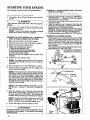
STARTING YOUR ENGINE ................
9
10
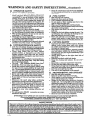
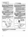
SPECIFICATIONS
ENGINE
TYPE:
2-Cycle,
Air Cooled
DISPLACEMENT:
32cc
ENGINE RPM:
Operating-,7500
Idle- -2600-3400
SERIAL NIFMBER
AND STARTING
INSTRUCTIONS
ROPE HANDLE
ENGINE
SWITCH
IGNITION:
Solid State
IGNITION TIMING:
Spark Advance Nonadjustable
m,,
.,,,,, .
,,.
CARBtYRETOR:
ENGINE
.... • ,,R
"OFF":
.ll
,,
/
............
Diaphragm All Position
With Adjustable Fuel
Mixture Jets
,N
,,,,,,,,,,u,
i
i
Positive Switch
, i
SHOULDER
STRAP CLAMP
THRO_
TRIGGERW/LOCK
SAFETY
LABELS
.................................
STARTER:
Auto Rewind
MUFFLER:
Temperature Limiting
(not spark arresting)
Trimmer Head: 18"
Blade: 8" I,.,I ll,ll
,I
CUTTING PATH:
HHI.ll
HANDLEBAR
STARTER
I
SHOULDER
STRAP
TRIMMER
FUEL TANK:
500ee
SPARK PLUG:
Champion (CJ - 14)
SPARK PLUG GAP:
.025"
LINE LIMITER
, ,,,
MODULE
FUEL(
'....................
AIR GAP:
/
METAL
SHIELD
,,,,,,
BLADE
.010"to.014"
LUBRICATION:
Gasoline/Oil
Mixture- 40:1
CUTTING LINE:
.060"Diameter
FILTER
line
PRIMER
BULB
& GUAP,D
Y_t.N_FACTUR]RD U'NDER ONE OR MORE OF THE FOLLOWING U.S. PATENTS:
4,0_,9L_;
4,052,789; 4,112,653; 4,161,820;, 4,16_',812_ 4, 185,138; 4,189,833; 4_I1,004;
4_8B,67_; 4,362,074; 4,451,983; 4,841,929; 4,940r028; & D324,051. OTHER U.S. AND FOREIGN PATENTS PENDING.
SPECIAL
NOTICE
For users on U.S. Forest Land and in some states, including
California(Public
Resources
Codes 4442 and 4443), Idaho,
Maine, Minnesota,
New Jerse_ Oregon, andWashington:
Certain internal combustion engines operated on forest, brush, and/or
grass-covered
land in the above areas are requiredto be equipped with a spark arrestor, maintaine d ineffective working order, or the
engine must be constructed, equipped, and maintained
for the prevention of fire. Check with your state or local authorities for regulations pertaining to these requirements.
Failure to follow these requL_ements is a violation ofthe law. This unit is not factoryequipped with asparkarrestor;
however, a spark arrestoris available as an optionalpart. Ira sparkarrestoris requiredinyour area_
content your Authorized Service Dealer for the correct kit.
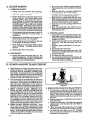
WARNINGS AND SAFETY INSTRUCTIONS
(See Additional Safety Instructions
,_,
DANGER
throughout this Manual)
-- THIS POWER
TOOL
CAN BE DANGEROUS!
This unit can cause serious
injury including amputation
or blindness
to the operator and others.
The warnings and safe_- ins_r_tctions in this manual must be followed to provide reasonable
safety and efficiency
in using the unit. The
operator is responsible
for following the warnings and instructions
in this manual and on the unit. Read
the entire Operator's Manual before assembling and using the unit! Restrict the use of this unit to persons who read,
understand, and follow the warnings and instructions in this manual and on the unit.
.......
ADANGER
BLADE
CAN THRUST
VIOLENTLY
AWAY FROM MATERIAL
IT DOES
NOT CUT..
-- BLADE THRUST CAN CAUSE
AMPUTATION
OF ARMS OR LEGS.
- KEEP PEOPLE AND ANIMALS
30 FEET (10 METERS) AWAY.
Leg Guards
W_NING
TRIMMER LINE CAN THROW
OBJECTS VIOLF,NTLY.
Thrown
bjects
-
YOU CAN BE BI3NDED
OR INJ't_.ED.
-
WEAR EYE AND LEG
PROTECTION.
.....,,,H
60 Foot (20 meter-)
Hazard Zone
Stop Coasting Blade
by Contact with
Material.
Safety
i
-
BLADE/TRIMMER
THROW OBJECTS
-
OTHERS CAN BE BLINDED
OR INJURED.
-
KEEP PEOPI.E AND ANIMALS
30 FEET (10 METERS) AWAY.
,,,N
LINE CAN
VIOLENTLY.
_k WAP,NING
BLADE COASTS
AFTER THE
THROTTLE
IS RELEASED.
-
THE BLADE CAN SERIOUSLY
CUT YOUOR OTHERS.
-
STOP THE BLADE WITH CUT
MATERIAL.
WARNING
READ
Labels
i
HAZARD ZONE FOR THROWN
OBJECTS.
A
Operator's
Manual
,,,,,,,,
OPERATOR'S
MANUAL.
-
FOLLOW ALL WARNINGS
AND INSTRUCTIONS.
-
F'_URE
RESULT
TO DO SO CAN
IN SERIOUS INJURY.
SAFETY ACCESSORIES
ITE_
S._____,_ C_)GGLESL_NG
PROTECTION
•. :..... • ._. •.. ................................
STOCK NO.
71-85707
_3_
ARNINGS
A
o
•
•
•
•
•
•
A
•
•
•
•
•
•
•
•
•
•
•
•
AND SAFETY INSTRUCTIONS....(Continued)
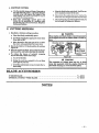
OPERATOR
A]w_v_
_,_r
s_e_
SAFETY
eve Drotect_0_.
boots, and gloves. Wearing safety leg guards is recommended. Do not go barefoot or wear sandals,
jewelry, short pants, short sleeves, loose clothing,
or clothing with loosely hangingties,
straps, tassels, etc.; they can be caught in moving parts. Be_fgt fully covered w;ffihelp protect you from pieces
oxic plants such as poison ivy thrown by blade
or trimmer head which could be more of a hazard
than touching the plant itself.
Secure hair so it is above shoulder length.
Do not operate unit when you are tired, ill, or under the influence of alcohol, drugs, or medication.
Wear hearing protection if you use the unit for
more than I- 1/2 hours per day.
Never start or run the engine inside a dosedroom
or building. Breathing exhaust fumes can kill.
Keep handles free of off and fuel.
Always use the handlebar and a properly adjusted
shoulder strap with a blade. See '_kssembly."
UNIT/MAIntENANCE
SAFETY
Look for and replace damaged or loose parts before each u_. Look for and repair fuelleaks before
use. Keep the unit in good working condition.
Throw away blades that are bent, warped,
cracked, broken, or damaged in any other way.
Replace trimmer head parts that are cracked,
Ch_pped,broken, or damaged in any other waybefore using the unit.
Maintain the unit accordingto recommended proeedures. Keep the blade sharp. Keep the cutting
line at the proper length.
Use only
.080" diameter SEAB._SLaser Line ®
brand line. Never use wire, rope, string, etc.
Install the required shield properly before using
the unit. Use the metal shield for all weed blade
use. Use the plastic shield for all line trimmer use.
Use only specified blade or trimmer head; make
sure it is properly installed and securely fastened.
Never start engine with dutch shroud removed.
The clutch can fly off and cause serious injury.
Be sure blade or trimmer head stopsturningwhen
engine idles.
Disconnect
the spark plug before performing
maintenance (except carburetor adjustments).
Make carburetor adjustments with the lower end
supported to prevent the blade or trimmer line
from contacting any object. Hold the unit by hand;
do not use the shoulder strap for support.
Keep others away when making carburetor adjustments.
Use only genuine SEARS
accessories as recommended for this unit.
_k
FUEL
SAFETY
•
•
•
•
Mix and pour fuel outdoors.
Keep away from sparks or flames.
Use a container approved for fuel.
Do not smoke or allow smoking near fuel or the
unit or while using the unit.
• Wipe up all fuel spills before starting engine.
• Move at least 10 feet (3 meters) away from fueling
site before star_g engine.
Stop engine and allow it to cool before removing
fuel cap.
• Empty the fuel tank before storing the unit. Use
up fuel lef_ in the carburetor by starting the engine and letting it run until it stops.
• Store unit and fi_eI in an area where fuel vapors
cannot reach sparks or open flames from water
heaters, electric motors or switches, furnaces, etc.
A
CUTTING
SAFETY
•
Inspect the areato be cut before eachuse. Remove
objects (rocks, broken glass, nails, wire, string,
etc.) which can be thrown or become entangled in
the blade or trimmer head.
• Keep others including children, animals, bystanders, and helpers outside the 60 foot (20 meter)
Hazard Zone. Stop the engine immediately if you
are approached.
• Always keep engine on the right-hand
side of
yourbody.
• Hold the unit firmly with both hands.
• Keep firm footing and balance. Do not overreach.
• Keep blade or trimmer head below waist level.
• Do not raise the engine above your waist.
• Keep allparts ofyour body away from blade, trimmer head, and muffler when engine is runrming.
• Cut from your right to your left.
• Use only for jobs explained in this manual.
A
TRANSPORTINGAND
STORAGE
:
Stop the unit before carrying.
Keep the muffler away from yourbody.
Allow engine to cool and secure unit before storing or transporting
it in a -vehicle.
Empty the fuel tank before storing or transporting the unit. Use up fuel left in the carburetor by
starting the engine andlettingit
run until it stops.
• Store unit and fuel in an area where fuel vapors
cannot reach sparks or open flames from water
heaters, electric motors or switches, fbxnaces, etc.
• Store unit so the blade or line limiter cannot accidentally cause injury. The unit can be hung by the
bracket below engine or by drive shaft housing.
• Store the unit out of reactfof children.
If situations
occur which are not covered in this manual,
use care and good judgment.
If you need assistance,
contact your Authorized
Service Dealer or the
CUSTOMER ASSISTANCE
HOTLINE at 1-800-235-5878.
-4-
IIIIIIIIIII
IIIIII
I
I
III
IIIIIIIIIIIIIIIIIIIIIIII
II
IIIII
II,,,,IH ,I
I I ,,,,,,,,,II
II
I,II
II
,,,,, ,ll I I
,,,,,,,,,,,,
KNOW "fOUR UNIT
i
J
,,,,,,
,
,,,,,,,,
.......................................
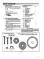
c. CARTON
CONTENTS
A. INTRODUCTION
Your too! is a versatile product developed for large
lawns and to make short work of a variety of lawn
care tasks -- trimming, scalping, mowing, and
sweeping.
DESCRIPTION
" En_ne
• _DriveShaftAssemb!y
Special Features Include:
t 18" Cutting Path
o
Semi-Automatic
Trimmer Head
o
Heavy Duty Precision
Clutch _
32cc Engine
o 8" Brush Blade
•
•
•
QTY
1
w/Safety
Label
•
•
•
•
•
•
0
Meta! Shield
Plastic Shield
8" Brush Blade
8" Weed Blade
Trimmer Head
Handlebar with Throttle Trigger
Assembly
Shoulder Strap w/Warning
40:1, 2-cycle Engine Off
Operator's Manual
Loose Parts Bag
I
i
I
i
1
I
i
I
i
1
I
PARTS BAG CONTENTS:
Cover- Handlebar
1
1. After removing the contents from the carton,
Retention Plate
t
check parts against the Carton Contents list.
1
Hex Wrench - 5/32"
Hex Wrench - 3/16 _
1
2. Examine the parts for damage. Do not use damFlex Shat_ Lube
1
agedparts.
Hex Socket Screw
2
B. Screw
4
3. Notil_ yaur SEARS Store immediately if a part
C.
Screw
6
is missing or damaged.
2
D. Hex Nut
Your unit has been shipped with a plastic
1
* E. Flange HexNut
* E Beveled Washer
1
shipping guard over the primer bulb (see "Spec* G. FlatWasher
1
ifications" for location).
Remove and discard
H. Grass Washer
1
the plastic shipping guard.
[ *
A WARNING
[
It is normal to hear the _el filter rattle in [Parts marked with * are critical and must be sup.
• :an empty fuel tank,
{plied by your SEARS Service Center. Failure to{
]use the proper parts can cause the blade to fly off
, ,i,_!_d sen_l_hurty0u
or0thers,
......
.....................
:,
[
B. DNPACKING
LOOSE
•
*
•
•
•
•
INSTRUCTIONS
D. HARDWAREUSAGE
HARDWARE
ACTUAL
NOT
SHOWN
SIZE
ThisHardware is packaged in the Plastic Bag. Refer to
the Hardware reference letters below during assembly.
©
A.
B.
C.
R
H.
E.
G,
Figure 1
-5-
ASSEMBLY
(if tool is received assembled,
justed for the operator.)
repeat
all steps
in this section
This Operator's Manual is designed to help you assemble the tool and to provide its safe operation. It is
important that you read the entire manual to become
familiar with the tool before you begin assembly. If
you have any questions or need further assistance,
call our CUSTOMER ASSISTANCE HOTLINE at
1-800-235-5878.
i
i
,,,m,,,,,
ii i
ii
B.ASSEMBLY
iii
i,,,,,,,,, ,,,i
ii
is correct
-
Small Hex Wrench (provided)
Large Hex Wrench (provided)
Adjustable Wrench
Standard Screwdriver
iiiiiiiiiiiiii
i
i
ii
ii iiii i
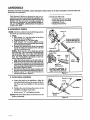
STEPS
MII
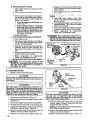
2. HANDLEBAR
ScrewsA.
u IV
I
\
material
maytube.
be
onthe endthat
of the
/
Locknuts D.
Close up view
; Hole
It may be necessary to
turn the arbor shaft to
align with the square hole.
Figure 2
|,
,,,,,,, ,,,,JUl, II
i
,
i
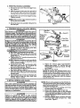
ASSEMBLY
a. Locate the decal on the handlebar.
Align the
mounting block between the arrows on the decal; then, seat the handlebar in the mounting
block.
Cover
handlebarand alignscrewholes.
c. Insertscrews"C."and tightensecurely.
NOTE: Refer to the illustration on the front cover for
proper positioning.
i
iiii
ii iii
i
/
Handlebar
b.Positionthe coverbetween the arrowson the
,,,11111
and is ad-
2. Tools you will need:
Hardware referred to in the following sections
are shown in actual size in Figure I.
1. TUBE
a. Place screws "A." into the holes on the front
shroudas shown in Figure2.
b. Position
locknuts"D."inlowerholes.
c. Hold locknuts "D." in place; tighten screws
with small hex wrench (provided) just enough
to hold hardware together.
d. Remove the packing cover from the straight
end of the tube if so equipped. Your unit may
not have a packing cover.
_TE:
Make sure the drive shaft does not fall
out of the tube. Dirt on the shaft will significantly
reduce the life of the unit. If the drive shaft falls
out of the tube, dean, re-lubricate,
and re-instal!. See "Drive Shaft Lubrication" in the Customer Responsibilities section.
e. Align the bottom groove on the tube with the
ridge on the lower wall of the engine opening.
f. Turn the arbor shaft at the bottom of the tube
as necessary to _
the square endofthe shaft
with the square h01e inside the front opening of
the engine. Figure 2 (inset).
g. Firmlypush _abeinto the engine openinguntil
the nose cone contacts the foam grip. Figure 2.
h. Tighten screws "A_" alternately ,_ith the hex
wrench until secure. Figure 2.
ii i
to be sure assembly
Block
Figure 3
i !
H
3_
THROTTLE
HANDLE
ASSEMBLY
a. Remove the rear screw from the trigger housing. Figure 4.
b. Slide the trigger housing onto the right side of
the handlebar. Align screw holes in the trigger
housing with the screw hole in the handlebar.
c. Reinstall the rear screwin the trigger housing.
Tighten securely.
Make sure the engine switch is located on
the top side of the handle.
d. Secure the loosewire
the shaft pad.
..............
assemblyin
i
4. TRIMMER
HEAD
IIHI
& PLASTIC
Screw
Hole
the groove in
II
I
Wire Assembly
In Shaft Pad
Figure 4
IIIIIIIIIIIIIIII
I
SHIELD
Gear Box
Widest Part
of Shield
Toward
[ _
A WARNING
,_tv_e
to install the shield in the position shown
_in Figure 5 can result in serious injury to the op[era tor, The length
of the shield must be ali_rned
[with the length of the tube. Direct the widest
]part of the shield toward the engine,
a: Remove and discard the packing cover from
the arbor shaft ffso equipped,
The, line limiter (on the underside
ld) m sharp and can cut you.
b3 Place the shield under the gear box and insert
four screws "B." through the gear box into the
= shield. Figure 5.
c, Tighten screws "B." evenlyandsecurelywith
a
standard screwdriver.
O__0___-:_,
Althou go h ascrowdrivers!otmpromdedm
.
•
screws "B.', It Is easier to mstall the screws
with a wrench or socket.
d. Install grass washer "H." over the arbor shaft.
Make sure grass washer "H," is against and
___ved over the dust cup, Figure 5.
e. b2art threading the trimmer head onto the arbor shai_ as shown in Figure 5.
f. Align the hole in the dust cup with the hole in
the center front of the gear box by turning the
trimmer head.
g. Insert the large hex wrench (provided) into the
aligned holes to keep the arbor shaft from
turning. Figure 5 (inset).
Arbor Shaft
Line
Trimmer
_Direction
to Install
Figure 5
h. Tighten the trimmer head counterclockwise
against grass washer "H." and the dust cup
while holding the large hex wrench. See Figure 5 (inset).
- . -i. Remove the hex wrench.
NOTE: To remove the trimmer
head, insert
the hex wrench into the aligned holes in the dust
cup and gear box. Unthread the trimmer head. Be
sure to store the grass washer, plastic shield, 4
shield screws, and hardware
with the trimmer
head for future use.
iii
5, METAL
SHIELD
AND
ii ,,,,,,,,m
i i
,,li!,mu,llli
i
IHIIlll
BLADE
A DANOER
The metal shield must be properly
installed
on
the tool any_m, e the tool _s used with the blade.
The forward
tip on the metal shield helps to re.
duce the occurrence
of blade thrust which can
cause serious injury such as amputation
to the
operator
or bystanders.
A pAN E
Dust Cup
....
!
Failure
to _astall
the shield
in the position I
shown in Figures 6 and 7 can result in serious [
injury to the operator. The length of the shield[
must be aligned with thelength
of the tube. Di- [
reef widest pa.-_of the shleldtow ,ardthe engine.[
NOTE: Ifyour unit is equipped as aline trimmer, remove the trimmer head, grass washer, and plastic
shield before instalh'ngthe
metalshield
and blade: ....
Store parts for future use.
a. Remove and discard the packing cover from
the arbor shaft, ff so equipped.
b. Remove the dust cup. Save for later use.
e. Position the retention plate on the underside
of the metal shield and align screw holes. Make
sure the flat side of the plate is against the metalshield.
Figure6.
d. Hold theretention
plateinpositionand place
the metal shieldunder the gear box. Align
screwholes.Figure6.
-7-
e. Insert the four shield screws "C." one at a time
through the gear box and shield, then thread
them into the retention plate.
f. Tighten the screws evenly and securely with
Screw c.* !
g. iI_.DL_ _i=_d_s_ o_p over _i_ ea'bor sh_.
h. Install blade over arbor shaft, making sure the
hole in the center of the blade is fitted around
the raised center on the dust cup. Figure 6.
When installing blade, make sure teeth
on blade are oriented as shown in Fig-are 6.
i. Install the large flat washer "Go', cupped
washer "E", and nut "E." as shown in Figure 6. Be sure cupped washer "E" is installed
as shown in Figure 6 (inset).
j. Align hole in the dust cup with the hole in the
side of the gear box by _ting
the dust cup.
k. Insert the large hex wrench (provided) into the
aligned holes. Figure 6 (inset, upper left).
1. While holding the hex wrench in position,
firmly tighten nut "E." countp_rclockwise with
a wrench.
rn_Remove thehexwrench.
n. Turn blade by hand. If the blade binds against
shield, blade is not centered. Reinstall blade.
NOTE: To remove the blade, align holes as in
step "j.'; then, insert the large hex wrench.
Unthread hex flange nut andremoveparts.
Be
sure to store the blade, fiat washer, cupped
washer, and hex flange nut for future use.
6. SHOULDER
i
I j,
Toward
Washer
E*
Blade I .........
/
#€I (see inset)
I
Nut Z.*
...................................
Figure 6
STRAP
I
A wAm ]r G
Proper
shoulder
strap and handlebar
adjust-[
ments before
starting
the engine are required[
for safe and efficient
use.
[
a_ Try on shoulder strap and adjust for fit and
balance before starting the engine and beginning a cutting operation,
b. Insert your right arm and head through the
shoulder strap and allow it to rest on your left
shoulder. Make sure the danger sign is on your
back and the hook is to the right side of your
waist. Figure 7.
Modify these initial adjustm __ts as necess _ary
for comfort and control but do not locate the
handlebar mounting block below the point of
the arrow on the safety labels. Do not locate the
shoulder strap clamp in any position other
than between
the engine and handlebar
m0un_g
block.
OPERATING
POSITION
A one-half twist is built in the shoulder
strap to allow the strap to rest fiat on the shoulder.
c. Adjust the strap so that the hook will be about
10 inches below the waist when the hook is attached to the shoulder strap.
d. Fasten shoulder strap hook to clamp and lift
tool to the operating position. Figure 7.
e. Check for the following
1. Left arm extended, hand holding handlebar
Danger Sign
Centered on
"four Back
grip.
2. Right hand holding trigger handle, fingers on
throttle triggen
3. Engine below waist level.
4. Shoulder strap pad centered on left shoulder.
5. Danger sign centered on your back.
6. Full weight of tool on left shoulder.
7. Without operator bending over, the blade or
trimmer head is near and parallel to the
ground m_d easfiyconta_s
material to be cu_.
-8-
Washer G.*
Washer E*
Figure 7
OPERATION
.................................................
BEFORE
A
STARTING
_,,_,_
........................................
ENGIr_:
WARNING
BE SURE TO READ THE FUEL SAFETY
INFORMATION
IN THE WARNINGS
AND SAFETY INSTRUCTIONS
SECTION OF THIS MAN-tlAL BEFORE YOU
BEGIN.
IF YOU DO NOT UNDERSTAND
THE
FUEL SAFETY SECTION, DO NOT ATTO FUEL YOUR I_NIT;, SEEK
HELP FROM SOMEONE
WHO DOES
UNDERSTAND
THE FUEL
SAFETY
SECTION OR CALL THE CUSTOMER
ASSISTANCE
HOTLINE
AT
1-800 -235-5878.
,
2-CYCLE
..............
J
ill
i
,,,,,ill i
i
i
OIL:
CRAFTSMAN 40:1 2 cycle oilis strongly recommended.
This off is specially blended with fue! stabilizers
for
increased fuel stability (extends fuel life up to 5 times
longer') and reduced smoke.
If CRAFTSMAN 2 cycle oil is not available, use a good
quality 2 cycle AIR-COOLED
engine oil that has a
recommended fuel mix ratio of 40:1.
IMPORTANT!
•
AUTOMOTIVE
•
BOAT OILS
Do not use:
OIL
(NMMA, BIA. etc.)
These oils do not have proper additives for 2-cycle,
AIR-COOLED
engines and can cause engine damage.
GASOLINE
The two-cycle engine on this product requires a fuel mixture of regular unleaded gasoline and a high quality engine oil for Iubrication of the bearings and other moving
parts. The correct fuel/oil mixture is 40:1 (see Fuel Mixture Chart). Too little oil or the incorrect oil type will
cause poor performance and may cause the engine to overheat and seize.
Gasoline and oil must be premlxed in a clean approved fuel
container. Always use fresh regular unleaded gasoline.
IMPORT _ANT:
Experience
indicates that alcohol
blended fuels called gasohol (or using ethanol or methanol) can attract moisture, which leads to oi!/gas separation and formation of acids during storage. Acidic gas can
damage the fuel system of an engine While in storage. To
avoid engine problems, the fuel system should be emptied
before storage for 30 days or longer. Drain the gas tank,
then run the fuel out of the carburetor and fuel lines by
starting the engine and letting it run until it stops. Use
fresh fuel next season. See STORAGE instructions
for
ad&'tional information.
Never use engine or carburetor
cleaner products in the fuel tank or permanent damage
may occur.
FUEL STABILIZER
Fuel stabilizer is an acceptable alternative in minimizing
the formation
of fuel gum deposits during storage. Add
stabilizer to gasoline in fuel tank or storage container.
Always follow the fuel mix ratio found on the stabilizer
container. Run engine at least 10 minutes after adding
stab'_zer to allow the stabilizer to reach the carburetor.
You do not have to drain the fuel tank for storage if you are
using fuel stabilizer.
CRAFTSMAN 40:1 2 cycle engine off is specially blended
with fuel stabilizers. If you do not use this Semrs off, you
can add afuel stabilizer (such as Craftsman No. 33500) to
y_r ._ael
ta_.
GASOLINE
AND
OIL iVIIXTURE
Mix gasoline and oil as follows:
•
Consult chart for correct quantities.
• Do not mix gasoline and oil directly in the fuel tank.
FOR ONE GALLON:
-
Pour 3.2 ounces of high quality, 2-cycle engine oil
into an empW, approved one gallon gasoline container.
°
Add one gallon of regular unleaded gasoline to the
gallon container, then securely replace the cap.
Shake the container momentarily.
•
The mixture is now ready for use. Fuel stabilizer
can be added at this time if desired; follow mixing
instructions
on the label.
FUEL MIXTLrRE CHART
40:1 Fuel:Oil
Mix Ratio
.....
t
1 gallon
Oil (ft. oz,)
3.2
1.25 ga!lons
4.0
2.5 gallons
8.0
]
STARTING YOUR ENGI-r TE
(For location
_L,t: _._
•
of controls,
_ £.__
refer
_£_
STARTING A WARM ENGINE
RUN OUT OF FUEL:
to "Specifications.")
L._'_G_._:
Fuel engine. Move 10 feet (3 meters) away from i_Jeling site.
The trimmer
starts.
$
head
will turn when
A WARNING
the engine
I
Rest engine and shield on ground, supporting trimmer head off ground.
Remove and discard t_e plastic shipping
guard on the primer bulb (if so equipped).
STARTING A COLD ENGINE, OR A WARM ENG]Y_E AFTER RUI_G
OUT OF FUEL:
*
e
t
e
Make sure the switch is in the "On" position.
Move the choke lever to the "Full Choke" position.
Slowly press the primer bulb 6 times.
Engage the throttle lock as follows
1.) press the throttle lock-out
2.) squeeze and hold the throttle trigger
3.) press and hold the throttle lock, then
4.) release the throttle trigger
Keep the throttle lock engaged until the engine runs
smoothly.
o PulI starter rope sharply 5 times.
$
Engage the throttle
THAT HAS NOT
lock as directed in "SARTING
untiI the engine runs smoothly.
Pull starter rope sharply until engine runs, but no
more than 5 pulls.
$ Allow the engine to run 15 seconds, then move the
choke lever to '!Off Choke." Release the throttle zoc_
by squeezing and releasing the trigger.
If engine has not started, pull starter rope 5
more pulls. If engine still does not run, it is probably
flooded. Proceed to "Starting a Flooded Engine."
To stop the engine, move switch to the "Off" position.
STARTING A FLOODED ENGINE:
Flooded engines can be started by placing the swi'tch_.
in the "On" position and the choke leverin the "Off
Choke" vesition; then, pul! the rope to clear the engine of excess fuel. This could require pu!ling the
starter rope many times depending on how badly the
unit is flooded.
If the unit still doesn't start, call the Customer Assistance Hotline at 1-800-2355878.
1STARTING pOSITION t
The en_e
may sound as if it is trying to
start before the 5 pull. If so, go to the next step immediately.
t
•
Move th e choke lever to the "H_f Choke" position.
Pull the starter rope sharply until the engine runs,
but no more than 6pulls.
If the engine has not started after 6 pulls (at
half choke), check to make sure the switch and the
choke lever are in the proper positions. Then, move
the choke lever to the "Fuli Choke" position and
press the primer bulb 6 times; pull the starter rope 2
more times. Move the choke lever to "Half Choke"
and pull the starter rope until the engine runs, but no
more than 6 more pulls.
Throttle Lock
STOP
Switch
Choke Lever
Allow the engine to run 15 seconds, then move the
choke lever to "Off Choke." Allow the unit to run for
30 more seconds at "Off Choke," then release the
throttle lock by squeezing and releasing the trigger.
H_LTFA If engine dies with the choke lever at the "Off
Choke" position, move the choke lever to "Half
Choke" and pull the rope until the engine runs.
•
To stop the engine, move the switch to "Off."
,i
A WARN .IN G
IAvoid any bodily contact with the muffler
when
] start inca warm engine. A hot muffler can cause
[serzous burns.
- 10 -
Throttle
Lock-Out
.......
If the engine still has not s_rtod, it isprobably flooded. Proceed to "Starting a Flooded Engine."
$
A
GOLDENGINE, .... "Keep the throttle lock engaged
Primer
Bulb
OPERATING
INSTRUCTIONS
•
When using the blade, bring the engine to full
throttle before entering the material to be cut. The
Blade has maximum cutting power at full throttle
and is less likely to bind_ stall, or cause blade thrust,
which can result in serious injury to the operator or
o_ers. Refer to "Guard A_st
Blade Thrust".
• When using the trianmer bead, do not run the engine at a higher speed than necessary. The cutting
line will cut efficiently when the engine is run at less
• than full throttle. At lower speeds, there is less engine noise and vibration. The cutting line wil! last
longer and w_ be less likely to "weld" onto the spoo!.
• If the blade or trimmer
head does not turn
when the engine is accelerated,
make sure the
drive shaft housing is properly seated in the engine
shroud. Refer to '_,ssembly Steps-Tube."
• Always release throttle
trigger and allow engine to return to idle speed when not cutting.
• The blade or trimmer
head should not turn
when the engine runs at idle speed. If the blade
or trimmer head turns when the engine is at idle
speed, refer to the "Trouble Shooting Chart."
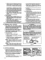
• To stop engine:
• Release the throttle trigger.
• Move ignition switch to the "Off" position.
• StopthebladebyalIowingthe"9o'clock"position to contact cut material. Figure 8.
USING
"'
Blade
Coasts
Figure8
YOUR UNIT AS A LINE TRIMMER
A
WAR_[_rG
- TH:ROWS
OBJECTS
The rapidly moving line causes objects to be
thrown violently. The shield will not provide
complete protection to the operator or others.
The operator
must wear a safety
face
shield or goggles.
Always wear heav_
longpants
and boots. Keep others atleast
30 feet (10 meters) away.
Leg Guards
nn
Face
Shield
]Stop Coasting Blade by Contact with Cut material.
Boots
A
60 Foot
/
Semi-Automatic
(20 meter)
Hazard Zone
WARI" NG - HAZARDZONE
This tool will throw objects and cut. Keep others including
children, animals, bystanders and helpers at least 30 feet ( 10 meters)
away from the operator
and tool. Stop
the engine if you are approached.
Trimmer Head
WARNING-
DAMAGED
TRIMMER
HEAD
Trimmerl£ead
parts that'_re Chipped, cracked.
or damaged in any other way can fly apartand
cause serious injury. Do not use. Replace
damaged parts before using the tool
IIIIIIIHI
A. LINE
TRIMMER
IIIII
II
JI
Ill
IIIIIIIIIUIIIIIIII
Ill Ill
Illlll,,ll,,ll,
I
illllllllllllllllllIll
illlll
I
Jllllllll
Illllllll
Ill
SAFETY
1. OPERATOR SAFETY
a. Always wear eye protection when operating,
Servicing, or performing maintenance
on your
_t.
See "_vty Accessories."
b. Do not operate this tool when you are tired, ill
or under the influence of alcohol, drugs, or
medication.
- 11 -
c. Always wear heavy,long pants,longsleeves,
boots,and gloves.Do notgo barefootor wear
sandals, short pants, short sleeves, jeweh-T_
loose clothing, or clothing with loosely hangshoulderlength.Beingfullycoveredwillhelp
protect
you from piecesoftoxicplantssuchas
poisonivythrown by theblade,Which couldbe
more ofahazardthan touchingtheplantitself.
d. Do notswing thetoolwithsuchforcethatyou
indanger oflosingyourbalance.
e. Never startor run the engineinsidea c!osed
room or building.Breathingexhaustfumes
can kill.
f. Keep handles free of oil and fuel.
TOOL SAFETY
a. Inspect the entire tool before each use. Replace damaged parts. Check for fue! leaks and
make sure all fasteners are in place and securely fastened.
b. Use only .080" diameter SEARS brand line.
Never use wire or rope, string, etc.
c. t_e sure the shield isproperly attached.
d. Make sure trimmer head is properly installed
and securely fastened. Refer to "Assembly."
e
III I
e. Be sure trimmer head stops turning when engine idles. See "Carburetor Adjustments."
f. Make carburetor adjustments with the drive
shaft housing supportsd to prevent the trim.
I
I
/1/
B. TRIMMER
I
II
l
LINE
I
II
'
3. C_G
SAFETY
a. Inspect the area to be cut before each use. Remove objects (rocks, broken glass, nails, wire,
string, etc.) which can be thrown or become entangled in the trimmer head.
b. Always keep the engine on the right side of
your body.
c. Hold thetoo!fn_alywithboth hands.
d. Keep finnfootingand balance.Do notoverreach.
e. Keep thetrimmer head below waistlevel.
f. Do notraisetheengineaboveyourwaist.
g. Keep allpartsofyourbody away fromthetrimmer lineand mufflerwhen engineisrunning.
h. Use onlyforjobsexplained
in thismanual.
I !!!Ill
Ill Ill
Ill
IIIII III I I I
ADVANCE
•
The trimmer
line will advance
approxi.
mately 2 inches each time the bottom of the
trimmer head is tapped on the ground with
the engine _-.u_g
at full throttle.
•
The most efficient
line length is the maxi,
mum length allowed by the line llmiter.
•
Always keep the shield in place
tool is being operated.
Figure 9.
•
To Advance
1. Operate
g. i_eep others away when ma_ng ca_'bure_or adjustments.
h. Use only SEARS accessories or attachments
as
recommended.
when
Use
only
.080"
A WARNING
diameter
SEARS
the engine at full throttle.
to and above
Always tap trimmer head on a grassy
are_ Tapping onsurfaces
such as concrete or
asphalt can cause excessive wear to the trimmer head.
To Advance Line,
Tap Bottom Of
Trimmer Head On
Ground One Time.
Line Limiter Cuts Line
To Proper Length.
If the line is worn down to two
inches or less, more than one tap will be re:
quired to obtain the most efficient line length.
I
//
C. CUTTING
I
Illlllllllllllllll
I I
I
II Illlll
IIIIIIIIIIIIIIIII I
I I
Illlllllll I
Illllll
METHODS
•
The tip of the line does the cutting.
You will
achieve the best performance and minimum line
wear by not crowding line into cutting area. The
right and wrong ways are shown in Figure 10.
•
For trimming
or scalping,
use less than full
throttle to increase
line life, especially_
- during light duty cutting.
- near objects around which the line can wrap
such as small posts, trees or fence wire.
- 12 -
Figure 9
Work Area
Figure 10
The (
lll_ll
line.
the
3. Tap bottom of trimmer head lightly on ground
one time, See Figure 9. Approximately
2_ of
line will be advanced with eac_ tap.
I
brand
Line:
2. Hold the trimmer head parallel
the grassy are_
[I
I I IIII
!!!Ill
_llllllllllllllll
•
•
The line will eas il y remove grass and weeds
from around walls, fences, trees and flower
beds, but it also can cut the tender bark of
trees or shrubs and scar fences. To help avoid
damage especially to delicate vegetation or trees
with tender bark, shorten line to 4-5 inches and
use at tess than full throttle.
For mowing or sweeping, use furl throttle
for
a good clean job.
i
A WArniNG
3 Inches
Above _
Ground ]
]
Tip of the Line
Does the Cutting
Figure
Use minimum
speed and do not crowd the line[
when cutting around hard objects (rock, grave!, [
fence posts, ere), which can damage the trimmer[
head,
become
entangled
in the line, or be[
thrown causin_ a serious hazard.
[
11
SCALPING
3 Inches
Above Ground
Figurei2
1. TRIMMING - Figure I1. Hold bottom of the
trimmer head about 3 inches above ground and at
an angle. Allow only the tip of the line to make
contact. Do not force trhnmer line into work area.
2. SCALPING
- Figure 12. The scalping technique removes unwanted vegetation.
Hold the
bottom of the trimmer head about 3 inches above
the ground and at an angle. Allow the tip of the
line to strike ground around trees, posts, monuments, etc. This technique increases line wear.
3. MOWINGFigure
13. Your trimmer is ideal
for mowing in places conventional lawn mowers
cannot reach. In the mowing position, keep the
line parallel to the ground. Avoid pressing the
head into the ground as this can scalp the ground
and damage the tool.
4. S _WEF_ING - Figure
14. The fanning action
of the rotating line can be used for a quick and easy
clean up. Keep the line parallel to and above surfaces being swept and move tool from side to side.
D. LINE
MOWING
...........
_gure
SWEEPING
Figure
14
REPLACEMENT
•
For proper line feed:
- Use only genuine
SEARS pro-wound
spoo!s and .080" diameter
SEARS brand
line. Use of other types of spools or lines can
result in excessive breakage, line welding and
impropr line feed.
- Pro-wound
spools offer the most convertlent method
for replacing
line as well as
optimum performance.
• Always clean dirt and debris from spoo! and
hub when performing any type maintenance.
1. Installing
Spoolw]th
To Remove, Turn Lock Ring Counterclockwise
To Replace, Turn Lock Ring Clockwise
Line
a. Hold the trimmer head as shown inFigure 15.
Press the lock tab and turn the lock ring as
shown in Figure 15.
b. Remove the lock ring, tap button, and spool.
Figure 16.
c. Clean dirt and debris from all parts.
d. Inspect all trimmer head parts for damage. Replace damaged parts.
V
13
A WA ± NO
Figure 15
Hub
f
I
]Trimmer
head parts that are chipped, cracked,[
[broken,
or damaged
in .any other way can fly[
[apart and cause serious x_ur_ Do not use. Re-[
LPlace damaged parts before u_ag _bthetoo!.
,
Lock Ring
- 13 -
The aluminum line saver (Figure 17 ) can
become worn during use. After a groove is worn
into line saver, remove it from trimmer head, turn
it upside down, and reinstal! it (with spool re-
e. Follow "Installing Spool with Line," steps
"e i "
If the line breaks off or backs up in the trimmer head, follow "Installing
Spool w/Line,"
tigh_iy
wound o_:uxes_ooLi.za_ing
4,,-6
inchesof
extendedline.Contin&ewithsteps%.-i.
The line saver must be installed only from the in-[
side of the _'._er
head. If installed on the out- I
side of the trimmer head, the line saver can fly l
oxt and become a dangerous
missile.
[
e. Insert the end ofthe line throughthe line saver.
Figure 17. Place spoolintrimmerhead.
Press
spool down, then turn it enough to lock lugs on
spool under tugs on drive gear. Figure 16.
Make sure the line is not caught between
the rim of spool and the wall of trimmer head.
f.
Catch
Lock Tab
Catch
Replace the tap button.
Align the lock ring
over the catches on the hub;push the lock ring
down on the hub and turn it clockwise until the
catches lock into place. Figure 17.
AWARNING
Catch
_gure 17
I
All catches
must be fastened
and the lock tab]
latched
in the Lock Ring.
If installed
incor-!
rectl3_ the Lo.ck Ring can fly off and become a l
dangerous
mmsile.
t
k
\.
,._ _
kct
/
Approximately
Be Pulled From the Trimmer Head
r/Each
g. Make sure lock ring is properly fastened by
pulling on it and trying to turn it counterclockwise. If it comes off, reinstall it properl3t
h. Pull on the line to change the spool from the
locked position to the operating position.
i. Obtain the correct line length (4-6 inches) by
pressin._ tl_e tap button(Figure
18 ) and pullmg on me line again.
Each time the tap button is pressed, approximately 2 inches ofline can be pulled from
the trimmer head: Figure 18.
2. Spool
2 Inches of Line Can
Time the Tap Button is Pre_ed.
Figure18
Replacement
a. Replace the spool when the square corners on
the lugs are rounded off, reduced in size, or broken off. Figure 19.
b. To replace the spool, follow the instructions in
"Installing Spool with Line."
3. Installing
.
Line
on Spool
....
To replace the Line on existing Spool:
a. Follow "Installing
Spool w/Line,"-steps
'!a-d." and remove any line remaining on
the spool.
b. Use a 40 foot length of.080" SEARS brand
line.
c_ Insert 1/16" to 1/8" of the end of the line
through the hole in the spool. Figure 20.
Allow no more than 118" line to extend inside the spool.
d. Wrap the line onto the spool fmnly_and
evenly in a clockwise direction as shown by
the arrow on the spool. Figure 20.
NOTE: The line must be wrapped firmly and
evenly for proper line feed.
MAINTENANCE
SEMI-AUTOMATIC
SPOOL W/nINE
For bestresults,
use only.080"
SBAP_ brand line.
Wrap Line on Spool
as Shown by Arrow
Figure 20
71-85807
952-701523
NYLON
CUTTING UNE
100 Ft .........................
200 Ft ..........................
400_.
- 14-
Line
ACCESSORIES
HEAD ........
...................
Figure19
(.080 dia.)
71-85771
71-85608
....
€_.-8o,_
_o
USING
YOUR UNIT AS A BRUSHCUTTER
The 8 inch Brush
in diameter.
_k
DANGER
Blade is designed
to cut grass, weeds,
- THIS POWER
TOOL
and woody brush and small trees up to 2 inches
CANBE
DyLNGEROUS!
Donotat_ach_blade
to this unit without the proper installation
of the Brush Blade Adaptor Kit #952-701616.
Blade usage
requires the proper installation
of all parts contained in the Kit. The Handlebar in the kit must be used
as abarrier
between the operator and the blade. Failure to use the handlebar can result in serious injury
to the operator.
This unit can cause serious injury including amputation or blindness to the operator and others.
The warnings and safety instructions in this manual must be followed to provide reasonable safety and efficiency in
uslng this unit. The operator is respons_le for fonowing the warnings and instructions in this manual and on the unit.
Read the entire Operator's Manual before using this unit! Restrict the use of this power tool to persons
who read, understand,
and follow the warnings and instructions
in this manual
and on the unit.
_k DANGER
- BLADE THRUST
When the spinning blade contacts anything it does not cut, a dan-
,4.
gerous reaction can occur causing the entire unit and
operator to be thrust violently in any direction. This
reaction is called Blade Thrust. As a result, the op.
erator can lose control of the unit. Use handlebar,
shoulder
strap,
and keep shield
in place.
Make sure others are at least 30 feet (10 meters) away.
Keep blade sharp.
Cut at full
throttle
and from your right to left.
Keep
hands, feet and unit in proper position;
refer
to "Guard Against Blade Thrust."
I
BLADE THRUST
DANGER
.787" (20ram)
>
8" Brush
....
Blade
(seeAccessoryList for partnumber)
Boots LegOuards
l' T own
..
WAF_NING
BLADE
- THROWS
OBJECTS
The rapidly moving blade causes objects to be
thrown violently. The shield will not provide complete protection to the operator or others. The operator must wear a safety face shield or goggles. Always wear safety leg guards and boots. Keep others
at least 30 feet (10 meters) away.
[ II !1
Eye Protection
^WARNING
&L
/_ X
- PROPER
Use only the 8 inch Brush Blade and proper
hardware
as shown.
The use of any other parts
can result in serious injury. Do not use any accessory or attachment
other than those recom.
mended by the manufacturer
for use with this
unit. Blades that are bent, warped, cracked, broken,
or damaged can fly apart and cause serious injury.
Do not use; Throw away.
•
\_
(20 meter)
!
_ntact with Cut material.
{
- HAZARD ZONE
This unit will throw objects and cut. Keep others
including
children,
animals, bystanders,
and
helpers at least 30 feet (10 meters) away from
the operator
and unit. Stop the eng_me and
blade immediately
if you are approached.
In areas where other people and animals
are present, such as near sidewalks, streets, houses,
etc., it is strongly recommended
that the operator
use the buddy system; that is, have another person
.serve as a "look out,?' keeping himself and others at
least 30 feet (10 meters) away from the operator.
WAP_TING
- COASTING
BLADE
The blade continues to spin after the engine is
stopped or the throttle is released.
The coasting
blade can thrust, throw objects, or seriously cut you
if accidentally touched. Stop the blade by leaving it in contact
with material
alread_
cut.
Use the "9 o'clock" pos_hon as the point of
contact.
- 15 -
A. BLADE
SAFETY
I. OPERATOR
b. Be sure the metal shield is properly attached.
The metal shield must be installed for all blade
usage.
c. Make sure the blade is _roperly installed and
securely fastened. Refer fo "_h__sembl_"
d. L_ sure the bl_
st:,pa _ur_'fing whsn tb.s engine idles. See "Trouble Shooting Chart."
e. Make carburetor adjustments with the drive
shaft housing supported to prevent the blade
from contacting any object. Hold unit by hand;
do not use the shoulder strap for support.
f. Keep others away when making carburetor adjustments.
g. Have all maintenance
and service not explained in this manual performed by an Authorized Service Dealer.
SAFETY
a. Always wear eye protection
when operating,
b. Always wear heavy,longpants,long sleeves,
boots,and gloves.Do notgo barefoot
or wear
sandals,jewelry,short pants,short sleeves,
looseclothing,
or clothing
with loosely
hangingstraps,
ties,
tassels,
etc.;
theycanbe caught
in moving parts. Secure hairso itis above
shoulderlength.Beingfiffiy
coveredwillhelp
protectyou from piecesoftoxic
plantssuchas
poisonivythrown by theblade,
which couldbe
more ofa hazardthan touchingtheplantitself.
c. Do notoperatethisunitwhenyou aretired,
ill,
or under the influenceof alcohol, drugs, or
medication.
d. Always use the handlebar and a properly
justed shoulder strap. See "Assembly."
3. _G
SAFETY
a. Inspect thearea to be cut before each use. Remove objects (rocks, broken glass, nails, wire,
string, etc.) which can be thrown or become entangled in the blade.
b. Always keep the engine on the right side of
your body. Hold the unit fmnly with both
hands.
c. Keep firm footing and balance. Do not overreach.
d. Keep blade below waist level.
e. Do not raise the engine aboveyour waist. The
blade can come dangerously close to your body.
f. Cut at full throttle.
g. Cut from your right to your left.
h. Use only for jobs explained in this manual. Do
not use the blade as an edger. The shield does
not provide adequate protection.
ad-
e. Do not swing the unit with such force that you
are in danger of losingyour balance.
f. Never start or run the engine inside a closed
room or building.Breathingexhaustfumes
can kill.
g. Keep handles
2. UNIT
free of oil and fuel.
SAFETY
a. Inspect the entire unit before each use. Replace damaged parts. Check for fuel leaks and
make sure all handles, guards, and fasteners
are in place and securely fastened.
B. GUARD
•
AGAINST
BLADE
THRUST
Blade Thrust is a reaction that only occurs when
using a bladed unit. This reaction can cause serious injurysuch as amputation.Carefully
study
thissection.Itisimportantthatyou understand
what causesbladethrust,
how you canreducethe
chance of itsoccurring,
and how you can remain
in controlofthe unitifbladethrustoccurs.
• The forwardtipon the shield
helpstoreducethe
occurrenceofbladethrustbut cannotpreventthe
occurrence.The operatormust followallwarnings and safetyinstructions
in thissectionto
lessenthechanceofbladethrustoccurring
and to
maintaincontrol
ofunitifthereaction
doesoccur.
1. WHAT
CAUSES
BLADE
THRUST
Blade
Thrust can occur when the spinningblade contactsan objectthatitdoesnotcut.This contact
causestheblade to stopforan instantand then
suddenly move or "thrust"away from the object
that was hit. The %hrusting" reaction can be violent enough to cause the operator to be propelled
in any direction and lose control of the unit: The
uncontrolled
unit can cause serious injury if the
blade contacts the operator or others, Figure 21.
2. WHEN BLADE THRUST
OCCURS.
Blade
thrust can occur without warning if the blade
snags, stalls, or binds. This is more likely to occur
in areas where it is difficult to see the material being cut. Byusingthe
unit properly, the occurrence
of blade thrust Will be reduced and the operator
will be less likely to lose control.
- 16 -
BLADE THRUST
•
3o
REDUCE
Figure 21
THE CHANCE
OF BLADE
THRUST
a. Cut only grass, weeds, and woody brush up to 2
inches in diameter with the brush blade. Do not
let the blade contact material it cannot cut such as
stumps, rocks, fences, metal, etc., or dusters of
hard, woody brush having a diameter greater than
2 inches.
b. Keep the blade sharp. A dullblade is more likely to
snag and thrust.
c. Cut only at full throttle. The blade has maximum
c_tting power at full throttle and is less likely to
bind or stall.
d. "Feed" the blade deliberately and not too rapidly.
The blade can thrust away if it is fed too rapidly.
e. CUt only from your right to your left. Swinging
the unit in the same direction as the blade spins
increases the cutting actiom
4. MAI_TAIN
CONTROL
a. U_sethe shoulder strap and keep a firm grip on
the unit with both hands. A properly adjusted
shoulder strap will support the weight of the
unit, freeing your arms and hands to control
and guide the cutting motion.
b. Keep feet comfortably
spread apart and
braced for the possibility of a sudden, rapid
thrust of the unit. Do not overreach. Keep fi)zn
footing and b_ance.
c. Keep the blade beIowwaist level. It will be easier to maintain control of the unit.
d. Do not raise the engine aboveyour waist as the
blade can come dangerously close to your body.
e. Do not swing the unit with such force that you
are in danger of losing your balance.
C. CUTTINGMETHODS
1. Establish a rhyth_c
cutting procedure.
a. Plant feet firmly, comfortably apart.
b. Cut While swingingthe
from right to left.
upper part ofyourbody
e. Move forward to the next area to be cut after
the return swing and plant feet once more.
Direction
to Cut
2. Use the 8 o'clockto 10 o'clockpositio n for cutting.
Figure 22.
3. Stop the engine and blade, then uncIip the shoulder strap from unit before clearing cut material.
4. To reduce the chance of material
around the blade, follow these steps:
Cut Between
the 8 o'clock
and 10 o'clock
Position
wrapp'mg
Figure 22
a. Cut at full throttle.
b. Swing the unit into material
your right to your left.
c:/Avoid the material just cut as you make the re.
' turn swing.
iiiiiiiiiiiiiiiiiii
A
to be cut from
iiiiiii
iiiiiiii
i
iiiiiii
!
The operator
or others must not try to clear I
away cut material
with the engine running or_
the blade turn_g
to avoid serious injury,
i
!
iiiiiiiiiiiiiiiiiiiiii
i
IIIIIIIH
III
I!111111
I
..........
i
..............................
BLADE ACCESSORIES
8" BRUSH BLADE .................
OPTIONAL
4
PO_W_
8
_
WEED
. ......................................................
BLADE
.......................................
71-85728
.
............
71_857_9
NOTES
- 17-
CUSTOMER
RESPONSIBILITIES
A. MAINTENANCE
--
MAINTENANCE
SAFETY
6_ Be sure blade or trimmer head stops turrdng when
2. Never start engine with clutch shroud removed.
The clutch can fly apart and cause serious i_ury.
3. Disconnect
maintenance
the spark plug before performing
except for carburetor adjustments.
4. Make carburetor adjustments with the lower end
supported to prevent the trimmer line from contatting any object.
5. Keep others
justments.
,H
away when making
carburetor
ad-
7. Replace blade or trimmer head parts that are
cracked, chipped ,or damaged in any other way be8. Use only
.080" diameter
SEARS brand line.
Never use wire, rope, string, etc.
9. Use only genuine SEARS
replacement parts as
recommended.
10. Inspect the entire unit. Replace damaged parts.
Check for fuel leaks and make sure all fasteners
are in place and securely fastened.
............................
B. FLEXIBLE
Lubricate
..........
DRPv_E SHAFT
the drive
, ,H,
i
i HI i
LUBRICATION
shaft:
- After each ten (10) hours of operation.
- Before operating if the unit has been stored for
90 daysor longer.
To order flexshaft lube, see the Accessory
List forthe proper part number.
If the engine is hot, avoid touching the muffler.
A hot muffler can cause serious burns.
_
,
Laythe drive shaft on a clean sure. Avoid laying shaft on the floor, ground
or on any other surface that may have dirt
or debris.
Even after wiping
the shaft,
Take care to avoid injury to your
hands and fingers with broken
wires when
checking
for damage or wiping
the drive
shaft. A cloth will not prevent broken wires
from puncturing
or tearing your skim
I. Remove thegearbox clamp screw and thelocatingscrewfrom the gearbox. Figure23.
2. Remove gearbox from thetube. Figure23.
3. Remove the driveshaftfrom the tube. Figure 23 (inset).
4. Check drive shaft for broken wires, twists, or
kinks, and replace if damage is foun&
5. Using a clean cloth, wipe the surface of the
drive shaft thoroughly to remove any old
grease.
6. Apply a uniformcoat ofhbe to the entire surface of the driveshafh
7. Inject the remaining contents of the container
into the top of the tube.
8. Reinstall the drive shaft in the tube.
Figure 23 (inset).
9. Reassemble
the gear box to the tube.
Locating
Screw
Tighten
Gear Box
be/
Gear Box
Clamp Screw
i i
i
,i ,,
iiiii
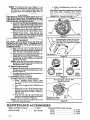
C. AIR FILTER
A dirty air filter decreases the life and
performance of the engine and increases fuel consumption.
1. Clean the Air Filter:.
Choke
Exit Slot
Air
Filter
Always after 5 tanks of fuel or 5 hours of
operation,
which-ever
is less.
More frequentI_
in dusty
conditions.
a_ Loosen the two screws on the a_ filter cover
enough to remove the cover from the engine. Figure 24.
b. Remove air filter from cover. Figure 24.
c. Wash filter in soap and water.
d. Squeeze filter dry and replace in cover.
| CAUTION: I Do not clean the air fdter in gasoline
or other flammable
solvent
to avoid
creating
a fire hazard.
- 18 -
Corners
Choke
Figure
24
e. Reinstall the air filter cover, making sure
the choke exit slot (Figure 24 ) is placed
over the choke lever.
I CAUTIQN: [ Make sure air filter is fitted into
corners of the cover to keep dust from entering engine and causing engine damage.
If replacin_
the air filter, see the
Accessory List for t_e proper par_ number.
D. CARBURETOR
ADJUSTMENTS
N__D__TFA
This is a complicated
task. Read all warnings and instructions
thoroughly
before starting adjustments.
If you do not think that you completely
understand
all warnings and instructions,
let your
Authorized
Service Dealer perform these adjustments.
2. BASIC CARBURETOR SETTINGS
_T_
In most cases, your engine can be made to
run properly with minor carburetor adjustments.
Refer to "Trouble Shooting Suggestions" in the
lef_ column for the condition you are experiencing
and follow the instructSons. The basic carburetor
settings are provided below.
a. Turn thelow speed mixture screw and the high
speed mix, re screw (Figure 25 ) clockwise
until they stop. Do not turn the screws until
they are tight as damage to the needle seatz can
DANGER
.Make carburetor
adjustments
with the lower
end supported
to prevent
blade or trimmer
line
from contacting
any object. Hold unit with your
hand,, do not use optional shoulder strap for sup.
port.
_eep others
ustments.
A WAltZING
away when making
carburetor
ad-
occur.
A WARNn G
[
Serious injury to the operator and others can oc- |
cur if the carburetor
is not properly adjusted.
J
•
•
•
•
1.
Poor engine performance
can be a result of
other causes such as dirty air filter, carbon
build-up
on muffler
outlets,
etc.
See
"Trouble Shooting
Chart" before proceeding with carb_tretor adjustments.
The carburetor
has been carefully adjusted
at the factor_
However, the operator must
be sure that a_ustments
are made when
any of the con .ditions occur as mentioned
on
the next page m "Trouble
Shooting Suggestions".
Very small adjustments
can affect engine
performance.
It is important to turn the screw a
very small amount per adjustment and test performance before making further adjustments.
Each adjustment should be no more than the
width of the slot in the adjusting screw.
This is a complicated
task and it is important to follow instructions
in sequence
as
indicated.
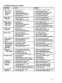
TROUBLE SHOOTING SUGGESTIONS
- Engine will not continue to run at idle position. See "Idle Speed Adjustment" and "Low
Speed Mixture Adjustment."
- Blade or trimmer head continues to spin when
the engine idles. See "Idle Speed Adjustment"
and "Deceleration Check."
- Engine dies or hesitates when it should accelerate. See "Acceleration Chec_"
, Loss of cutting power which cannot be corrected by cleaning the air filter. See "High
Speed Mixture Adjustment."
- Engine does not return to idle from full throttle within
2 seconds.
See "Deceleration
Check."
.....
- Engine will not run. See "Trouble Shooting
Chart."
Then, ff the carburetor requires adjustment, begin with "Basic Carburetor
Settings."
b. Turn the low S_eed mixture and high speed
mixture screws between three-quarters
and
one fi_ turn counterclockwise.
3. ADJUSTING
PROCEDURE
a. PREPARATION
1. Useafresh fuelmix. See"FuelingYourEngme,"
2. Make sure the line extends to the length allowed by the line limiter to provide correct
load on engine.
3. Startthe engine. Cut grass for 3 minutes to
warm enghle. The engine must be at operating temperature before carburetor ddjustments can be performed correctly,
b, IDLE SPEED ADJUSTMENT
1, Allow engine to idle,
2. Adjust idle speed screw (Figure 25 ) until
engine continues to run without stalling
and without blade or trimmer head moving.
- Turn screw clockwise to increase engine
speed if the engiae stalls or dies.
- Turn screw counterclockwise to slow engine down and/or to keep blade or trim,
mer head from turning.
3, Follow
instructions
in
'Ykcceleration
Check" and "Deceleration Check."
4. No further adjustments
are necessary
if the blade or trimmer head does not
turn at idle speed and if performance
is satisfactory.
c. ACCELERATION
CH_CK
1. Allow engine to idle.
2. Squeeze trigger fully
v_ If performance
is satisfactor_
proceed to "d. Deceleration Check,"
b. If the engine does not accelerate
smoothl_
turn the low speed mixture
screw (Figure 25 ) counterclockwise
a
small amount (no more than the width
of the slot in the adjusting screw).
3. Repeat step "2.)" until smooth acceleration
is obtained.
It ma_ be necessary to repeat "Idle Speed
Adjustment
through _cceleration
Check, to
obtain correct adjustments.
4. Follow
instructions
in
"Deceleration
Check."
- 19 -
d. DECELERATIONCHECK
1. Support the lower end so the trimmer line
is off the ground and will not make contact
with any object.
2. Allow engine to idle, then squeeze throttle
1. Allow en_e
to idle, then squeeze throttle
trigger fully.
2. Allow engine to run at ful! speed for about 1
3. Release the throttle trigger to the idle position and listen to the deceleration of the engine. It must return to idle smoothly and
within 1 to 2 seconds.
a. If performance
ceed to step "4."
is satisfactor_
throttle.
3. Turn high speed mixture screw (Figure 25 ) very slowly clock_me until engine
speed is reduced.
4. Turn high speed _e
screwvery slowly
counterclockwise.
Stop when the engine
begins to run roughly.
5. Turn screw slowly the minimum amount
clockwise until the engine runs smoothly.
6. Follow
instructions
in
"Acceleration
Check" and "Deceleration Check".
pro-
b. if the engin, e slow.lv or erratically
returns
to idle or Idles erratically,
repeat "Idle Speed Adjustment" or continue thr_agh Low Speed Mixture and
High Speed Mixture Adjustments to obtain proper deceleration.
4. Recheck idle speed.
e, LOW SPEED MIXTURE ADJUS22YIEN_r
[-CA_
If the engine does not operate according to these instructions
after repeatthe adjusting steps, do not use the unit,
Take it to your Authorized
Set'Ace Dealer.
1. Allow engine to idle.
2. Turn the low speed mixture screw (Figure
25_) slowly cl_oc]Awi'se
until the speed starts
to drop. Note this position.
3. Turn the low speed mixture screw counterclockwise until the speed increases and
then s_rts to drop agmn. Note this position.
High Speed
4. set the low speed mixture screw at the midpoint between the two positions.
5. Follow
instructions
in
"Acceleration
Check" end "Deceleration Check,"
f. HIGH SPEED MIXTURE ADJUSTMENT
[__
/
Idle Speed
Adjustment
Do not operate
engine at full
for prolonged
periods while makhigh speed adjustments
as damage to
the engine can occur.
_ttle
iHi
H,H
I ,, ,,I ,I
E. STARTER
•
I
,
Low Speed Adjustment Screw
"Nose Cone _'
Screws
Air Filter
Cover
crew
Figure 25
.................
ROPE
Replace a starter rope that breaks.
Clutch
Shroud Screws
I
A DANGER
Never start the engine with the clutch shroud re- ]
moved. The clutch will fly apart and cause seri- I
ous u
I
A WARNING
Do not remove the retaining
tab and screw or
The spring beneath the pulley is un.
out and cause serious inhousing assembly
is
rope, do not use unit.
Service Dealer.
1. Disconnect spark plug wire. Figure 26.
2. Removethe screw from the trigger housing.
to Figure 4 ).
(refer
3. Remove the trigger housing from the handlebar.
4. Carefully pu_ wire assembly out of the foam grip.
5. Loosen two "Nose Cone" screws and remove the
tube from the clutch shroud. Figure 26.
6. Remove the four clutch shroud screws with the
small hex wrench provided. Figure 26.
7. Separate clutch shroud from engine. Figure 26.
-20-
"Nose Cone"
Screws
Plug
Wire
Clutch
Shroud
Figure 26
i
A DANGER
'{
Use only a hand tool to remove the clutch. Do n!?t].
use any type of motorized
unit or stril_e the l
clutch in any way. Otherwise,
the clutch will fly [
apart and cause serious injury.
I
8. Hold the "Flats" of the clutch with an adjustable
wrench. Figure 27 (inset). Remove the nut counterclockwise with a wrench.
Clutch will slide off the crankshaft intact.
Do not disassemble the clutch.
9. Remove the cupped washer, clutch, and large fiat
washer as shown in Figure 27.
10.Remove p_Lfltey-hous_mg _om eng:me. ,._re
27.
11.Remove the rope retainer screw. Figure 28. Remove any remaining rope from around the pulley
ratchet. Figure 29.
Pulley
Housing
12.Hold pulley housing as shown in Figure 29 (inset). Hand turn pulley clock_dse as far as it _AI go.
13.Turn pulley counterclockwise
until the pulley
notch is aligned with the housing notch next to the
pulley tab and screw. Figure 29.
14.Next, turn the pulley one complete turn counterclockwise until the notches are aligned again.
15.Insert the he_xwrench into the hole formed by the
notches to hold the pulley in position.
Figure 29 (inset-upper left).
16.Use a 42" length
of replacement
Cupped Washer
(Curved Toward Clutch)
Nut
Figure 27
rope.
17.Move away 10 feet (3 meters) from the fuel tank
with the replacement rope. Use a match and melt
both ends of the rope to prevent fraying.
_q_-'-
18.PUlI melted ends through a thick, clean ragwhile
rope is still hot to obtain smooth, pointed ends.
Screw
Pulley
Rope
19.Insert one end of the rope through the handle and
secure with a knot. Leave a 3/16" pigtail behind
the knot. Figure 29 (inset-upper
right).
Tail
Screw Post
20.Insert other end of the roPe through the rope exit
hole into the inside of the housing, into the pulley
and up through the pulley hole. Figure 29.
Figure 28
21.Wrap
the rope counterclockwise
around the
pulley ratchet and tuck loose end under the rope
at the pulley hole. Figures 28 & 29. Leave a 1
inch tail laying flat on top of the pulley between the
retainer rib and the retainer post. Figure 29.
The rope tail must not extend beyond the raised
circla on the pulley to prevent interference
with
the pulley tab_ Figure 29.
Rope Exit Hole
Retainer Rib
22.Thread rope retahier screw into the screw post.
Figure 29. Do not overtighten screw.
Raised
Circle
Pulley
23.Hold the rope taut at the rope exit hole so the
pulley will not move. Remove hex wrench. ,_JIow
rope to rewind slowly.
24.Make sure spacer is in place. See Figure 27.
verse steps I through 10 to re-assemble.
Rope
Retainer
Rope
Taft
ReNotch
When reinstalling
the _clutch,
tighten the nut until the cupped washer
is
flattened
against the clutch. Over or under
tightening
nut can cause engine damage.
Rope
Retainer
Screw/Pest
Pulley
Hole
Pulley Tab
and Screw
Housing
Figure 29
......
Illlllllllllllllllml
mill
Illllllllllllllllllll
_
II
Illlllll
I I
II
NOTES
- 21 -
E
BLADE
SHARPENING
1. Brush
Blade
2. 4 Point
Weed Blade
A WA NG
A WAP G
i blade. The _blade wi_ continue to spin after the
!engine stops or after the throttle
trigger has
ibeen released.
Make sure the blade has stopped
ieoastmg and disconnect
the spark plug before
iperforming
work on the blade.
•
Check blades for flatness periodieaU}_
Lay
the blade on aflat surface andinspect the blade for
flatness before sharpening. Throw away a blade
that is not fiat.
•
File or grind each edge in the same manner
to maintain
a balanced blade. Figure 30.
* The 4 point, 8 inch blade is reversible.
When
the cutting edge on one side becomes dull, turn the
blade over. When both sides of cutting edges become du_, the blade may be resharpened.
• Check blades for flatness periodically.
Lay
the blade on a fiat surface and inspect the blade for
flatness before sharpening. Throw away a blade
that is not flat.
A WARrinG
Always replace
a blade that is bent, warped,
cracked, or damaged in any other way. Never attempt
to straighten
and re-use
a damaged
blade. Use only the specified replacement
blade
A WAP NG
each edge in the same manner
a balanced blade. Figure 30.
handling
the blade
i
Wear protective
gloves when
or performing
maintenance
on
to help avoid injury.
the blade from cracking
or flying_
sharpening,
do not f'de within 1/4_
inch of the radii
BRUSH
File or _d
to maintain
A
WARNING
Always replace
a blade that is bent, warped,
cracked, or damagedin
any other way. Never attempt to straighten
and re-use
a damaged
Made. Use onlythe specified
replacement
blade.
Wear protective
gloves
when
or performing
maintenance
on
to help avoid injur_
handling
the blade
To prevent
apart after
•
shown
in Figure
30.
]
_k WARNING
"
!
To prevent
the blade from cracking
or flying[
apart after sheening,
do not file w_thin 1/4[
inch of the rad_ shown in Figure 30.
]
BLADE
File Or Grind
Blade As Shown
\
Fileor Grind Each
Edge in the Same
Manner to Maintain
a Balanced Blade.
O
MaintainRadius
In This Area
1/4 Inch
Sharpen This
Area Only
-
Radius
In This Arev_
Figure 30
_.._I
_
Maintai_Radius
MaintainRadi_
Sharpen This _'_pw
Area Only
Figure 81
MAYNTENANCE
FLEX SHAFT
SPARK PLUG
ACCESSORIES
LUBE .....................................................................
952-030139
...........................................................................
71-85854
G. TROUBLE
SHOOTING
!SYMl m
CHART
CAUSE
REMEDY
Engine willnot
startor w_ run
onlyfora few
secondsafter
starting.
1.
2.
3.
4,
5,
6,
1.
2.
3.
4.
5.
6.
Engine will not
idle properly.
t. Carburetor requires adjustment.
2 None of the above.
3. Throttle trigger screw too tight.
L See _Carburetor Adjustments. "
2. Contact your Authorized Service Dealer.
3. See the "Throttle Cable" sectiom
Engine will not
accelerate,lacks
power, or dies
under a load.
1,
2.
3,
4.
6.
1.
2.
3.
4.
5.
' Engine smokes
excessively.
Engine runshot.
Cutting attachment
turns at idle
speed.
_
l%el tank empty.
Engine flooded,
Spark plug not firing.
Fuel not reaching carburetor.
Carburetor requires adjustment
None of the above.
Air filter
Spark plug fouled,
Carburetor req_es
adjustment,
Muffler outlets plugged.
None of the above,
F_ll tank _th correct fuel mixture
See "Starting Instructions."
Install new plug/check ignition system.
Clean fuel filter; inspect fuel line.
See _Carburetor Adjustments."
Contact your Service Dealer.
Clean or replace air filter,
Clean or replace spark plug and re-gap.
See "Carburetor Adjustments,"
Contact your Authorized Service Dealer.
Contact your Authorized Service Dealer.
1. Air filter
2. Fuel mixture incorrect.
3, Carburetor requires adjustment.
1. Clean or replace air filter.
2, Refuel with correct fuel mixture.
3. See"Carburetor
Adjustments."
1.
2.
3.
4,
1.
2.
3.
4.
FueI mixture incorrect,
Carburetor requires adjustment.
Spark plug incorrect.
None of the above.
See "Fueling Your Unit."
See "Carburetor Adjustments."
Replace with correct plug.
Contact your Authorized Service Dealer.
1. See "Carburetor Adjustments."
2. Contact your Authorized Service Dealer.
3. Contact your Authorized Service Dealer.
1, Carburetor requires adjustment.
2, Throttle cable binding.
3. Clutch requires repair.
.....
Cutting attachment
stops under a load
or does not turn
when engine is
accelerated.
Line does not
advance or breaks
while cutting.
1,
2,
3.
4.
Drive Shaft not engaged,
Drive shaft broken .............................................
Carburetor requires adjustments.
Clutch requires repair.
1. Lineproperlyrouted
inhead.
Line improperly wound onto spool.
Line size incorrect.
Too little line outside hea&
Dirt accumulated on cover cut-outs.
1.
2.
3.
4.
Line size incorrect.
Incorrect spool.
Crowding line against material being cut.
Cutting at higher speed than necessary.
Line releases
continuously.
Line us.age is
excesslve.
......................
Remove cover. Check fine routing.
Rewind line tightly and evenly.
Use only .080" SEARS brand line.
Remove cover. Pull 4" of line to outside.
Clean cover cut-outs.
................
,,,,
,,,,,,,
1.
2.
3.
4.
...........
,
.,,
,,,,,,,,,,,,
Use only .080" SEARS brand line.
Use proper spool.
Cut with tip of line.
Reduce cutting speed.
1. Line improperly routed in head.
2. Spool/lugs worn or broken.
1. Remove cover. Check line routing.
2. Replace spool/trimmer head,
.
Line improperly routed in head.
2. Line size incorrect.
Cutting at tfigh speed around hard objects.
4. Crowding line against material being cut.
1.
2.
3.
4.
,.........
into head.
,,,
1. See '_ssembly, "Tube."
-2,-C_ontactyour
AuthorizedBe-_C_I)€alei_: ..........
3. See "Carburetor Adjustments."
4, Contact your Authorized Service Dealer.
1.
2.
3.
4.
5,
2.
3.
4.
5.
,,
Line welds on spool.
.........
_
,,,,,
.........
1. Too little line outside of head.
2. Lin e size incorrect.
..........................
Remove coven Check line routing.
Use only .080" SEARS brand line.
Reduce speed around hard objects.
Cut with tip of line.
...............
.,.,
1. Remove cover. Pull 4" of line to outside.
2. Use only ,080" SEARS brand fine,
-23-
SEARS BRUSHWACKER
TM
REPAIR PART LIST - MODEL 358.798270-
32cc
51
23
\
22
57
52
4
35-
54
55
63
27
14
10
11
12
13
14
15
16
17
18
19
20
21
22
23
24
25
26
27
28
29
24
Part
No.
530-047040
530-094650
STD541025
530-047139
530-092243
71-85807
530-O36742
530-069252
530-069256
STD511005
530-094570
534-235901
530-094639
952-030139
530-093896
530-093898
530-340007
530-328929
530-095121
530-094568
530-015775
503-098302
502-045002
530-094566
530-094640
530-094571
530-094616
530-094612
530-015328
Description
o-- 25
(_--13
48
49
.................................
t e7
...........
Description
No.
Throttle Cable Ass'y.
Drive Shaft Housing
Nut
Handlebar
Screw
Cutting Head Ass'y.
Drive Shaft Pad
_T" Handle" Ass'y.
Shield FAt Ass'y.
(Incl. #10,11 & 12)
Screw
Locknut
Dust Cup
Shaft Lubrication
Hub Ass'y.
Line Saver
Spring
Cap-Spring
Drive Gear
Gear Box Ass'_
Screw
Switch
Throttle Hsg. Ass'y.
Drive Shaft
Seal
Grass Washer
Screw
Screw
Lockwasher
59
61
6
33
26
Key
iNo.
1
2
3
4
5
6
7
8
9
.oo
i
30
31
33
35
36
37
38
39
40
41
42
44
46
47
48
49
51
52
53
54
55
56
57
58
59
60
61
62
63
No.
530-001642
530-001711
530-027615
530-094572
530-012207
530-094686
530-094417
530-015791
71-85787
530"401183
530-344102
53O-O94627
71-85728
530-015792
530-015492
530-015793
530-047144
530-031111
530"031098
530-029162
530-029163
530-029765
530-027778
530-027749
71-85729
530-015792
530-015492
i 530-093748!
530-082432
Lockwasher
Screw
Shield Retention Plate
Handlebar Bracket
Handlebar Clamp
Clamp Harness Ass'y.
Shoulder S_ap
Screw
Spool w/Line
Release Button
Cover
Shidd
Brush Blade
Washer
Washer
Nut
V_re Harness Ass'y.
Hex Wrench (5/32)
Hex Wrench (3/16)
Deca!-Shaft
Warning (Upper)
Decal - Shaft Warning_Lower)
Der_l-Shield
Decal-Handlebar
Warning
Decal-Blade
Direction
Weed Blade
Washer
Washer
Nut
Operators Manual
\
\
\
\
\
\
\
\
/
\
11
\
SEARS BRUSHWACY R
Part
No.
TM
REPAIR PART LIST - MODEL
358.798270-32cc
Description
Description
J
i
,
!
53 [!- (27:'.772
2
3
4
5
6
7
8
9
10
11
12
13
14
530-027529
530-027530
530-015849
530-015852
530-015254
530-038103
530-037930
530-069247
530 -014362
530-035349
t 530-019156
530-014347
530-027606
15
16
17
19
t530-019154
530-027593
530"027594
530-010960
20
21
530-015789
530-010934
Wave Washer
Choke Shutter
Air Filter Plate
Fuel Line Kit
Fuel Hck-up Ass'y.
Carburetor
Carburetor Gasket
Fuel Cap Ass'y.
Shroud & Tank Ass'y.
(ind. #9,10 & 13)
Crankcase/Shroud Gasket
Reed
Reed Stop
Connecting Rod Ass'y.
(IncL Bearings)
Crankshaft Retaining Ring
Crankshaft Ass'y.
22
23
24
530-015126
530-015772
530-014015
Flywheel Key
Screw
Crankcase & Crankcase
Air _itter Cover
Air Filter
Screw
Ass'y.(r cI.#20,2128
530-014016
30
530-047145
31
32
33
34
35
STD610603
530-015162
530-025875
t530-019178
530-069349
36
37
38
39
40
43
44
45
46
47
48
49
50
530-347987
530-027518
530--069291
55
56
57
58
59
60
61
62
63
64
65
66
67
68
69
70
71
72
73
74
75
76
77
530-029395
530-027569
530-010961
530-094189
530-069254
530-010964
530-015767
530-027511
530-015770
530-015769
530-015496
530-015788
530-015796
STD541137
530-035164
530-035166
530-035178
530-035106
530-035188
530-035031
530-035028
530-035014
530-035151
78
.79
80
81
82
83
84
85
530-035147
530-035036
530-035142
530-035141
530-035023
530-035208
530-035203
530-035260
& 66)
Crankcase Ass'y,
(Incl. #36-39)
Lead WlredGrommet
Ass'y.
Screw
Piston Pin Retainer
Piston Ring
Cylinder Gasket
Piston Kit (Ind. #32,33,
86
530-035!85
87
530-069276
88
89
90
91
92
93
530-015239
530-015717
530-027781
952-701612
530-037972
530-016085
&pin)
530-032t03
530-015787
530-019158
530-032102
530-069232
530-069257
530-036409
530-015823
530-039134
530-015128
530-012235
530-030077
530-015768
Inner Bearing
Retaining Ring
Crankshaft Seal
Bearing Outer
Rope Kit
Muffler Kit
Muffler Attachment Spring
Screw
Ignition Module Kit
Screw
Cylinder
Spark Plug
Locknut
Sc_rew
Spacer
Screw
*+
*+
+
+
+
+
+
*+
*+
*+
Screw
Screw
Spacer
Washer
Nut
Pump Gasket
Pump Diaphragm
Inlet Screen
Inlet Needle Valve
Metering Lever Spring
Metering Lever
Metering Pin
Metering Diaphragm
Metering Diaphragm
Gasket
Circuit
PlateGasket
ffi Speed Needle Spring
Hi Speed Needle
IdleNeedle
Idle Needle Spring
Idle Speed Spring
Idle Speed Screw
Carb. Kwik Repair Kit
( +Indicates Contents)
Carb.Gasket/Diaphragm
Fit (*In.cares
Contents
Engine Gasket Kit
(:_Indicates Contents)
Screw
Screw
Muffler Guard
Spark Arrestor
Bulb Ass'y.
Screw
Kit
Not Shown
530-061277
530-029735
26
Washer
Fan Housing
Starter Pulley Kit
(Incl. #45)
Starter Spring
Starter Handle
Ptflley Housing Ass'y.
Clutch Washer
Clutch Ass'y. Kit
ClutchHousing
Spacer
( el. #36)
28
52
53
54
instruction
Carton
Decal
I
III
I
IIIIIIIIII[ I[IIIIII
IIII_
IIII
IIIIIIIIIILIII
II IIII
II
IIII
IIII
IIIIIIIIIIIII
IIIILI
..................
NOTES
-27-
The Model Number will be found below the top handle with the Serial
Number A!w_v_ mention the Model N1_mber when requesting service or
All parts listed herein may be ordered from any Sears Service Center
and most Sears Stores.
Operator's
WHEN ORDERING REPAIR PARTS ALWAYS GIVE THE
FOLLOWING INFORMATION AS SHOWN IN THIS LIST:
Manual
1.
The PART NUMBER
8.
The PART DESCRIPTION
2.
The MODEL NUMBER
4.
The NAME OF ITEM --
358.798270-32cc
32cc Gas Brushwacker
If the parts you need are not stocked locally, your order will be sent
to a Sears Repair Parts Distribution Center for handling.
When you buy merchandise
from
Sears you get an extra value that
nobody else can offer -Sears Service.
Model No.
358.798270-32cc
Across town or across the country,
Sears Service is always near, providing
trustworthy,
competent
service technicians
using only
Sears specified factory parts.
Ho to Order
Repair Parts
SEARS
Your Sears Merchandise takes on added value when you discover
that Sears has Service Units throughout
the country.
Each is
staffed by Sears- Trained, professional technicians using Sears approved methods.
SERVICE
IS AT YOUR SERVICE
Sears,
m,,,,,i
Roebuck
and Co., Hoffman
,,,, ],, ,,,I,,,,,,,,,H,,,,H
,,,,
I
I I
',"'
'
I H
'
Estafes,
IL 60179
,IH IH
U.S.A.
,I
, I,,,IHI
muSX