1
Operating Instructions
Diesel engine
12V 4000 M73, M73L, M93, M93L
16V 4000 M73, M73L, M93, M93L
20V 4000 M73, M73L, M93, M93L
MS150047/02E
Printed in Germany
© 2012 Copyright MTU Friedrichshafen GmbH
This Publication is protected by copyright and may not be used in any way whether in whole or in part without the prior
written permission of MTU Friedrichshafen GmbH. This restriction also applies to copyright, distribution, translation, micro‐
filming and storage or processing on electronic systems including data bases and online services.
This handbook is provided for use by maintenance and operating personnel in order to avoid malfunctions or damage
during operation.
Subject to alterations and amendments.
Table of Contents
1 Safety
1.1
1.2
1.3
1.4
General conditions
Personnel and organizational requirements
Transport
Safety regulations for maintenance and
repair work
1.5 Auxiliary materials, fire prevention and
environmental protection
1.6 Conventions for safety instructions in the
text
5
6
7
8
11
14
2 Product Summary
2.1 Engine Layout
2.1.1 Product description
2.1.2 Engine layout
2.1.3 Sensors, actuators and injectors – Overview
DCL-ID: 0000017652 - 001
2.2
2.3
2.4
2.5
Engine side and cylinder designations
Engine – Main dimensions
Firing order
Technical Data
2.5.1 ENGINE DATA 12V 4000M93, heat
exchanger installed, EPA stage 2
2.5.2 ENGINE DATA 12V 4000M93, heat
exchanger installed, IMO
2.5.3 ENGINE DATA 12V 4000M93L, heat
exchanger installed, EPA stage 2
2.5.4 ENGINE DATA 12V 4000M93L, heat
exchanger installed, IMO
2.5.5 ENGINE DATA 16V 4000M93, heat
exchanger installed, EPA stage 2
2.5.6 ENGINE DATA 16V 4000M93, heat
exchanger installed, IMO
2.5.7 ENGINE DATA 16V 4000M93L, heat
exchanger installed, EPA stage 2
2.5.8 ENGINE DATA 16V 4000M93L, heat
exchanger installed, IMO
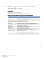
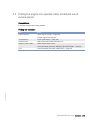
3.6 Fuel treatment system control cabinet –
Control elements
3.7 Tasks after extended out-of-service periods
(>3 weeks)
3.8 Checks prior to start-up
3.9 Fuel treatment system – Putting into
operation
3.10 Fuel treatment system – Switching on
3.11 Stopping the engine
3.12 Emergency engine stop
3.13 After stopping the engine
3.14 Fuel treatment system – Shutdown
3.15 Fuel prefilter – Draining
3.16 Plant – Cleaning
69
70
71
73
74
75
76
77
78
80
15
15
24
25
35
36
37
38
38
41
4 Maintenance
4.1 Maintenance schedule task reference table
[QL1]
81
5 Troubleshooting
5.1 Troubleshooting
5.2 Fuel treatment system – Troubleshooting
5.3 ADEC engine governor – Fault codes
82
85
86
44
47
50
53
56
59
6 Task Description
6.1 Engine
112
6.2 Cylinder Liner
114
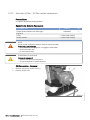
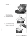
6.1.1 Engine – Barring manually
6.1.2 Engine – Barring with starting system
6.2.1 Cylinder liner – Endoscopic examination
6.2.2 Cylinder liner – Instructions and comments on
endoscopic and visual examination
6.3 Valve Drive
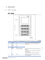
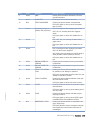
3 Operation
3.1 LOP – Controls
3.2 Putting the engine into operation after
extended out-of-service periods (>3
months)
3.3 Putting the engine into operation after
scheduled out-of-service-period
3.4 Starting the engine
3.5 Operational checks
68
62
64
65
66
67
6.3.1 Valve gear – Lubrication
6.3.2 Valve clearance – Check and adjustment
6.3.3 Cylinder head cover – Removal and
installation
112
113
114
116
118
118
119
123
6.4 Valve Gear
124
6.5 Injection Valve / Injector
125
6.4.1 HP pump – Filling with engine oil
6.5.1 Injector – Replacement
6.5.2 Injector – Removal and installation
124
125
126
MS150047/02E 2012-03 | Table of Contents | 3
6.6.1 Fuel filter – Replacement
6.7 Charge-Air Cooling
6.7.1 Compressor wheel – Cleaning
6.7.2 Intercooler – Check water drain for coolant
discharge and obstruction
6.8 Air Filter
6.8.1 Air filter – Replacement
6.8.2 Air filter – Removal and installation
6.9 Air Intake
6.9.1 Contamination indicator – Signal ring position
check (optional)
6.10 Starting Equipment
6.10.1 Starter – Condition check
6.11 Lube Oil System, Lube Oil Circuit
6.11.1 Engine oil level – Check
6.11.2 Engine oil – Change
6.11.3 Engine oil – Sample extraction and analysis
6.12 Oil Filtration / Cooling
6.12.1 Oil indicator filter – Cleaning
6.12.2 Automatic oil filter – Oil filter candles
replacement
6.12.3 Oil indicator filter – Check
6.12.4 Centrifugal oil filter – Cleaning and filtersleeve replacement
6.13 Coolant Circuit, General, HighTemperature Circuit
6.13.1
6.13.2
6.13.3
6.13.4
6.13.5
6.13.6
6.13.7
Venting points
Engine coolant – Level check
Engine coolant – Change
Engine coolant draining
Engine coolant – Filling
Engine coolant pump – Relief bore check
Engine coolant – Sample extraction and
analysis
6.13.8 Coolant filter – Replacement
131
131
133
135
136
136
137
139
140
140
141
143
168
6.18.1 Water drain valve – Check
6.18.2 Differential pressure gauge – Check
6.18.3 Water level probe (3-in-1 rod electrode) –
Check
6.18.4 Pump capacity – Check
6.18.5 Coalescer filter element – Replacement
163
162
163
170
171
172
6.20 Accessories for (Electronic) Engine
Governor / Control System
175
6.20.1 Start interlock limit switch – Check
6.20.2 Engine Control Unit ECU 7 – Checking plug
connections
6.20.3 Engine monitoring unit EMU – Plug
connection check
6.20.4 ECU 7 engine governor – Removal and
installation
6.20.5 EMU 7 – Removal and installation
151
160
161
168
169
174
6.19.1 Engine wiring – Check
146
149
153
154
155
156
157
159
167
6.19 Wiring (General) for Engine/Gearbox/Unit
144
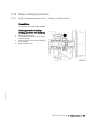
6.15 Battery-Charging Generator
4 | Table of Contents | MS150047/02E 2012-03
6.18 Fuel Supply System
144
153
164
165
167
6.17.1 Bilge pump – Relief bore check
138
139
164
6.17 Auxiliary PTO
138
162
6.15.1 Battery-charging generator drive – Coupling
condition check
6.16.1 Engine mounts – Checking securing screws
for firm seating
6.16.2 Engine mounts – Resilient element check
133
6.14 Raw Water Pump with Connections
6.14.1 Raw water pump – Relief bore check
6.16 Engine Mounting / Support
174
175
176
177
178
179
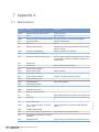
7 Appendix A
7.1 Abbreviations
7.2 MTU contacts/service partners
180
182
8 Appendix B
8.1
8.2
8.3
8.4
Index
Spare Parts
Consumables
Special Tools
183
185
187
191
DCL-ID: 0000017652 - 001
6.6 Fuel Filter
1 Safety
1.1 General conditions
General
In addition to the instructions in this publication, the applicable country-specific legislation and other com‐
pulsory regulations regarding accident prevention and environmental protection must be observed. This
state-of-the-art engine has been designed to meet all applicable laws and regulations. The engine may
nevertheless present a risk of injury or damage in the following cases:
• Incorrect use
• Operation, maintenance and repair by unqualified personnel
• Modifications or conversions
• Noncompliance with the Safety Instructions
Correct use
The engine is intended solely for use in accordance with contractual agreements and the purpose envis‐
aged for it on delivery. Any other use is considered improper use. The engine manufacturer accepts no
liability whatsoever for resultant damage or injury in such case. The responsibility is borne by the user
alone.
Correct use also includes observation of and compliance with the maintenance specifications.
Modifications or conversions
Unauthorized modifications to the engine represent a safety risk.
MTU will accept no liability or warranty claims for any damage caused by unauthorized modifications or
conversions.
Spare parts
Only genuine MTU spare parts must be used to replace components or assemblies. MTU accepts no
liability whatsoever for damage or injury resulting from the use of other spare parts and the warranty shall
be voided in such case.
Reworking components
TIM-ID: 0000000860 - 017
Repair or engine overhaul must be carried out in workshops authorized by MTU.
MS150047/02E 2012-03 | Safety | 5
1.2 Personnel and organizational requirements
Personnel requirements
All work on the engine shall be carried out by trained and qualified personnel only.
The specified legal minimum age must be observed.
The operator must specify the responsibilities of the operating, maintenance and repair personnel.
Organizational measures
This publication must be issued to all personnel involved in operation, maintenance, repair or transporta‐
tion.
Keep it at hand at the operating site of the engine so that it is available to operating, maintenance, repair
and transport personnel at all times.
Use the manual as a basis for instructing personnel on engine operation and repair with an emphasis on
explaining safety-relevant instructions.
This is particularly important in the case of personnel who only occasionally perform work on or around
the engine. This personnel must be instructed repeatedly.
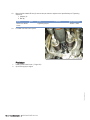
For the identification and layout of the spare parts during maintenance or repair work, take photos or use
the spare parts catalog.
Working clothes and protective equipment
Wear proper protective clothing for all work.
TIM-ID: 0000000874 - 018
Use the necessary protective equipment for the given work to be done.
6 | Safety | MS150047/02E 2012-03
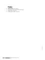
1.3 Transport
Transport
Lift the engine only with the lifting eyes provided.
The lifting eyes are designed for engine transport only, not for the transport of propulsion units (engine
and gearbox).
Use only the transport and lifting equipment approved by MTU.
The engine must only be transported in installation position, max. permissible diagonal pull 10°.
Take note of the engine center of gravity.
In the case of special packaging with aluminum foil, suspend the engine on the lifting eyes of the trans‐
port pallet or transport with equipment for heavy loads (forklift truck).
Prior to transporting the engine, it is imperative to install transportation locking devices for crankshaft and
engine mounts.
Secure the engine against tilting during transportation. The engine must be especially secured against
slipping or tilting when going up or down inclines and ramps.
Setting the engine down after transport
Place the engine only on an even, firm surface.
TIM-ID: 0000002621 - 002
Ensure appropriate consistency and load-bearing capacity of the ground or support surface.
Never place an engine on the oil pan, unless expressively authorized by MTU on a case-to-case basis to
do so.
MS150047/02E 2012-03 | Safety | 7
1.4 Safety regulations for maintenance and repair work
Safety regulations for maintenance and repair work
Have maintenance and repair work carried out by qualified and authorized personnel only.
Allow the engine to cool down before starting maintenance work (risk of explosion of oil vapors).
Before starting work, relieve pressure in systems and compressed-air lines which are to be opened.
Take special care when removing ventilation or plug screws from the engine. Cover the screw or plug
with a rag to prevent fluids escaping under pressure.
Take special care when draining hot fluids ⇒ Risk of injury.
When changing the engine oil or working on the fuel system, ensure that the engine room is adequately
ventilated.
Allow the engine / system to cool down before starting to work.
Observe the maintenance and repair instructions.
Never carry out maintenance and repair work with the engine running unless expressly instructed to do
so.
Secure the engine against accidental starting.
Disconnect the battery when electrical starters are fitted.
Close the main valve on the compressed-air system and vent the compressed-air line when pneumatic
starters are fitted.
Disconnect the control equipment from the assembly or system.
Use only proper, calibrated tools. Observe the specified tightening torques during assembly/disassembly.
Carry out work only on assembles and/or units which are properly secured.
Never use lines for climbing.
Keep fuel injection lines and connections clean.
Always seal connections with caps or covers if a line is removed or opened.
Take care not to damage lines, in particular fuel lines, during maintenance and repair work.
Ensure that all retainers and dampers are installed correctly.
Ensure that all fuel injection and pressurized oil lines are installed with enough clearance to prevent con‐
tact with other components. Do not place fuel or oil lines near hot components.
Do not touch elastomeric seals if they have carbonized or resinous appearance unless hands are proper‐
ly protected.
When working high on the engine, always use suitable ladders and work platforms. Make sure compo‐
nents are placed on stable surfaces.
Observe special cleanness when conducting maintenance and repair work on the assembly or system.
After completion of maintenance and repair work, make sure that no loose objects are in/on the assem‐
bly or system.
Before barring the engine, make sure that nobody is standing in the danger zone. Check that all guards
have been reinstalled and that all tools and loose parts have been removed after working on the engine.
The following additional instructions apply to starters with beryllium copper pinion:
• Breathing protection of filter class P2 must be applied during maintenance work to avoid health haz‐
ards caused by the beryllium-containing pinion. Do not blow out the interior of the flywheel housing or
the starter with compressed air. Clean the flywheel housing inside with a class H dust extraction de‐
vice as an additional measure.
8 | Safety | MS150047/02E 2012-03
TIM-ID: 0000000879 - 023
Note cooling time for components which are heated for installation or removal ⇒ Risk of burning.
Welding work
Never carry out welding work on the assembly, system, or engine-mounted units. Cover the engine when
welding in its vicinity.
Do not use the assembly or system as ground terminal.
Do not route the welding lead over or near the wiring harnesses of MTU systems. The welding current
may otherwise induce an interference voltage in the wiring harnesses which could conceivably damage
the electrical system.
Remove parts (e.g. exhaust pipes) which are to be welded from the engine beforehand.
Hydraulic installation and removal
Check the function and safe operating condition of tools and fixtures to be used. Use only the specified
devices for hydraulic removal/installation procedures.
Observe the max. permissible push-on pressure specified for the equipment.
Do not attempt to bend or apply force to lines.
Before starting work, pay attention to the following:
• Vent the hydraulic installation/removal tool, the pumps and the lines at the relevant points for the
equipment to be used (e.g. open vent plugs, pump until bubble-free air emerges, close vent plugs).
• For hydraulic installation, screw on the tool with the piston retracted.
• For hydraulic removal, screw on the tool with the piston extended.
For a hydraulic installation/removal tool with central expansion pressure supply, screw spindle into shaft
end until correct sealing is established.
During hydraulic installation and removal, ensure that nobody is standing in the immediate vicinity of the
component to be installed/removed.
Working on electrical/electronic assemblies
Always obtain the permission of the person in charge before commencing maintenance and repair work
or switching off any part of the electronic system required to do so.
De-energize the appropriate areas prior to working on assemblies.
Do not damage cabling during removal work. When reinstalling ensure that wiring is not damaged during
operation by contact with sharp objects, by rubbing against other components or by a hot surface.
Do not secure cables on lines carrying fluids.
Do not use cable binders to secure cables.
Always use connector pliers to tighten connectors.
Subject the device or system to a function check on completion of all repair work.
TIM-ID: 0000000879 - 023
Store spare parts properly prior to replacement, i.e. protect them against moisture in particular. Pack de‐
fective electronic components and assemblies in a suitable manner when dispatched for repair, i.e. par‐
ticularly protected against moisture and impact and wrapped in antistatic foil if necessary.
Working with laser equipment
When working with laser equipment, always wear special laser-protection goggles ⇒ Heavily focused ra‐
diation.
Laser equipment must be fitted with the protective devices necessary for safe operation according to
type and application.
MS150047/02E 2012-03 | Safety | 9
TIM-ID: 0000000879 - 023
For conducting light-beam procedures and measurement work, only the following laser devices must be
used:
• Laser devices of classes 1, 2 or 3A.
• Laser devices of class 3B, which have maximum output in the visible wavelength range (400 to 700
nm), a maximum output of 5 mW, and in which the beam axis and surface are designed to prevent
any risk to the eyes.
10 | Safety | MS150047/02E 2012-03
1.5 Auxiliary materials, fire prevention and environmental
protection
Fire prevention
Rectify any fuel or oil leaks immediately; even quantities of oil or fuel on hot components can cause fires
– therefore always keep the engine in a clean condition. Do not leave cloths soaking with fluids and lubri‐
cants on the engine. Do not store combustible materials near the engine.
Do not weld pipes and components carrying oil or fuel. Before welding, clean with a nonflammable fluid.
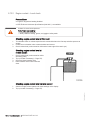
When starting the engine with an external power source, connect the ground lead last and remove it first.
To avoid sparks in the vicinity of the battery, connect the ground lead from the external power source to
the ground lead of the engine or to the ground terminal of the starter.
Always have a suitable extinguishing agent (fire extinguisher) on hand and familiarize yourself fully with
its handling.
SOLAS classification
On engines/plants with SOLAS classification, operational checks must include the following tasks:
• Check all covers (fitted in accordance with SOLAS requirements) on lube oil and fuel pipe connections
(>1.8 bar) for damage, replace as necessary. (→ Page 15)
Noise
Noise can lead to an increased risk of accidents if acoustic signals, warning shouts or sounds indicating
danger are drowned.
In all work areas with a sound pressure level in excess of 85 dB (A), wear ear protection (cotton wool,
ear plug or capsules).
Environmental protection
Modification or removal of mechanical or electronic components or the installation of additional compo‐
nents as well as the execution of calibration processes that might affect the emission characteristics of
the engine are prohibited by emission regulations. Emission control units/systems may only be main‐
tained, exchanged or repaired if the components used for this purpose are approved by MTU or equiva‐
lent components. Noncompliance with these guidelines might represent a violation of the Clean Air Act
and could involve the termination of the operating license by the emission authorities. MTU does not ac‐
cept any liability for violations of the emission regulations. MTU will provide assistance and advice if
emission-relevant components are intended to be modified. The MTU Maintenance Schedules ensure
the reliability and performance of MTU engines and must be complied with over the entire life cycle of the
engine.
TIM-ID: 0000002828 - 005
Only fuels of the specified quality required to achieve emission limits must be used.
In Germany, the VAwS (=regulations governing the use of plants that may affect water quality) is applica‐
ble, which means work must only be carried out by authorized specialist companies (MTU is an author‐
ized specialist company).
Dispose of used fluids, lubricants and filters in accordance with local regulations.
Auxiliary materials
Use only fluids and lubricants that have been tested and approved by MTU.
Fluids and lubricants must be kept in suitable, properly designated containers. When using fluids, lubri‐
cants and other chemical substances, follow the safety instructions that apply to the product. Take spe‐
cial care when using hot, chilled or caustic materials. When using flammable materials, avoid all sparks
and do not smoke.
MS150047/02E 2012-03 | Safety | 11
Lead
• When working with lead or lead-containing compounds, avoid direct contact to the skin and do not
inhale lead vapors.
• Prevent the buildup of white powder of lead.
• Switch on fume extraction system.
• After coming into contact with lead or lead-containing materials, wash your hands!
Acids and alkaline solutions
• When working with acids and alkalis, wear protective goggles or face mask, gloves and protective
clothing.
• If such solutions are spilled onto clothing, remove the affected clothing immediately!
• Rinse injured parts of the body thoroughly with clean water!
• Rinse eyes immediately with eyedrops or clean mains water!
Paints, enamels and varnishes
• When carrying out painting work outside the spray stands provided with fume extraction systems, en‐
sure that the area is well ventilated. Make sure that neighboring work areas are not impaired.
• No open flames!
• No smoking!
• Observe all fire-prevention regulations!
• Always wear a mask providing protection against paint and solvent vapors!
Liquid nitrogen
•
•
•
•
Store liquid nitrogen only in small quantities and always in specified containers without fixed covers.
Avoid body contact (eyes, hands). Contact of this nature would cause frostbite and numbing.
Wear protective clothing, protective gloves, closed shoes and protective goggles / safety mask!
Make sure that working area is well ventilated. Suffocation will result at 88% contamination of breath‐
ing air with nitrogen.
• Take great care not to subject containers, fittings and tools to impact or shock.
Compressed air
Compressed air is air compressed at excess pressure and is stored in tanks from which it can be extract‐
ed.
The pressure at which the air is kept can be read off at pressure gauges which must be connected to the
compressed air tanks and the compressed air lines.
• Pay special attention to the pressure level in the compressed air network and pressure vessel!
• Connecting devices and equipment must either be assembled for this pressure, or, if the permitted
pressure for the connecting elements is lower than the pressure required, a pressure reducing valve
and safety valve (set to permitted pressure) must form an intermediate connection. Hose couplings
and connections must be securely attached!
• Always wear protective goggles when blowing off tools or extracting chips!
• The snout of the air nozzle is provided with a protective disk (e.g. rubber disk), which prevents air‐
borne particles being reflected and thereby prevents injury to eyes.
• First shut off compressed air lines before compressed air equipment is disconnected from the supply
line, or before equipment or tool is to be replaced!
• Unauthorized use of compressed air, e.g. forcing flammable liquids (danger class AI, AII and B) out of
containers, results in a risk of explosion!
• Forcing compressed air into thin-walled containers (e.g. sheet metal, plastic, glass) for drying purpos‐
es or to check for leaks will result in a risk of bursting!
• Blowing dirt from soiled clothes while still worn is prohibited!
12 | Safety | MS150047/02E 2012-03
TIM-ID: 0000002828 - 005
When working with compressed air, safety precautions must be constantly observed:
Used oil
Used oil may contain harmful combustion residues.
TIM-ID: 0000002828 - 005
Rub your hands with skin protection cream!Wash your hands after contact with used oil.
MS150047/02E 2012-03 | Safety | 13
1.6 Conventions for safety instructions in the text
DANGER
WARNING
CAUTION
NOTICE
Note:
In the event of immediate danger.
Consequences: Death or serious injury
• Remedial action
In the event of potentially dangerous situations.
Consequences: Death or serious injury
• Remedial action
In the event of dangerous situations.
Consequences: Minor injury or material damage
• Remedial action
In the event of a situation involving potentially adverse effects on the product.
Consequences: Material damage.
• Remedial action
• Additional product information
This manual contains highlighted safety warnings in accordance with the US ANSI Z535 standard which
begin with one of the signal words listed above depending on the severity of the hazard.
Safety instructions
Read and familiarize yourself with all safety notices before starting up or repairing the product.
Pass on all safety instructions to your operating, maintenance, repair and transport personnel.
TIM-ID: 0000000881 - 018
1.
2.
14 | Safety | MS150047/02E 2012-03
2 Product Summary
2.1 Engine Layout
2.1.1
Product description
Description of the engine
Engine
The engine is a liquid-cooled four-stroke diesel engine, rotating counterclockwise (seen from driving
end), with direct injection, sequential turbocharging and charge-air cooling.
The engine is monitored by an engine control and monitoring system (ADEC).
Monitoring in the engine room is carried out by the engine control and monitoring unit (LOP).
Fuel system
Electronically controlled common-rail-injection system with HP pump, pressure accumulator (rail) and
single injectors with integrated individual store.
The electronic control unit controls
• Beginning of injection
• Injection quantity
• Injection pressure
Exhaust system
The exhaust system is equipped with triple-walled, water-cooled exhaust lines.
The triple-walled design permits
• low surface temperature,
• reduced amount of heat to be dissipated by the coolant,
• absolute gas-tightness.
Turbocharging
Sequential turbocharging with internal, engine-coolant-controlled charge-air cooling. The right-hand ex‐
haust turbocharger is cut-in and cut-out on 12V and 16V engines with electronically-controlled, hydrauli‐
cally-actuated flaps.
Cooling system
Engine cooling as split-circuit cooling system with plate-core heat exchanger.
TIM-ID: 0000010056 - 002
Heating of the charge air in idle and low-load operation prevents white smoke formation.
Seawater only flows through engine coolant and fuel heat exchanger as well as the raw water pump.
Service block
The service components are mounted on the auxiliary PTO end.
The arrangement facilitates easy access for maintenance operations.
MS150047/02E 2012-03 | Product Summary | 15
Service-components:
• Raw water pump, coolant pump
• Fuel duplex filter, switchable
• Automatic oil filter
• Centrifugal lube oil filter
• Coolant expansion tank
Electronic system
Electronic control and monitoring system with integrated safety and test system, providing interfaces to
Remote Control System (RCS) and Monitoring and Control System (MCS).
Electronic Engine Control Unit (ECU)
Functions:
• Engine speed control with fuel and speed limitation dependent on engine status and operating condi‐
tions;
• Control of sequential turbocharging, cylinder bank cut-out and air recirculation function.
• Data processing logistics for analog and binary signals;
• Interface for data transfer to CAN field bus for remote control and ship-side monitoring;
• RS 232 interface for connection of MTU dialog unit.
Electronic Engine Monitoring Unit (EMU), optional
Functions:
• Data processing logistics for analog and binary signals;
• Interface for data transfer to CAN field bus for remote control and ship-side monitoring.
Electronic Gear Control Unit (GCU), ship-side wall-mounting
Functions:
• Date processing logistics for gear coupling control;
• Input/output signals as well as data transfer to CAN field bus for remote control and ship-side monitor‐
ing.
Monitoring in engine room
Engine control and monitoring unit (LOP)
Functions:
• Alphanumeric, monochrome LCD display for monitoring of measured values as well as alarms when
limits are violated;
• Pushbuttons for menu control and dimming unit;
• Combined control and display elements for local engine/gear control;
• Flashing light and horn for combined alarm in engine room;
• Interface to CAN field bus for connected, communicating monitoring system components.
SOLAS – Fire protection specifications
All lines with SOLAS-compliant covers for pipe connections, according to MTU standard MTN5233, are
shown.
16 | Product Summary | MS150047/02E 2012-03
TIM-ID: 0000010056 - 002
Fuel system, fuel lines with fuel pressures exceeding 1.8 bar
1 Fuel line to fuel filter head
1 Fuel line from/to fuel filter head
TIM-ID: 0000010056 - 002
1 Fuel line to HP pump
MS150047/02E 2012-03 | Product Summary | 17
Lube oil system, oil lines with oil pressures exceeding 1.8 bar
All lines with SOLAS-compliant covers for pipe connections, according to MTU standard MTN5233, are
shown.
1 Parting line ETC oil supply free end
TIM-ID: 0000010056 - 002
1 Oil line on equipment carrier
18 | Product Summary | MS150047/02E 2012-03
1 Oil supply to HP pump
1 Oil supply to flap control free end
TIM-ID: 0000010056 - 002
1 ETC oil supply on main oil gallery
MS150047/02E 2012-03 | Product Summary | 19
1 Switching cylinder air flap turbo‐
charger B1
2 T piece flap control
1 Switching cylinder exhaust flap tur‐
bocharger B1
TIM-ID: 0000010056 - 002
1 Oil line from main oil gallery
2 Oil line to main oil gallery
20 | Product Summary | MS150047/02E 2012-03
1 Flap control distributor
1 Air recirculation valve
Special unions
TIM-ID: 0000010056 - 002
The following types of union are spray-proof in case of leakage even without covers and have been con‐
firmed as being SOLAS-compliant by GL and DNV.
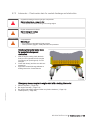
MS150047/02E 2012-03 | Product Summary | 21
Plug-in pipe union
Design precludes lateral spray as the point of separation is shielded by the sleeve (4).
Only seepage along the pipeline is possible whereby the pressure is greatly reduced by a faulty O-ring
(3).
The union is confirmed as being SOLAS-compliant by DNV and GL.
Screw plugs (2) are either sealed with copper sealing rings (1) as per DIN or O-rings (ISO).
The fluid must first pass the thread in case of a loose threaded union or faulty sealing ring (2).
The pressure is so greatly reduced by this and the faulty sealing ring (2) that any leakage is not under
pressure.
22 | Product Summary | MS150047/02E 2012-03
TIM-ID: 0000010056 - 002
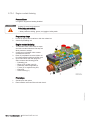
Plugs and sensors
High-pressure unions
1
2
3
4
5
6
7
Jacketed pipe
HP line
O-ring
Union nut
Recess for O-ring
Thrust ring
Leakage overflow bore
8
9
10
11
12
13
14
Thrust ring
Union nut
Union nut
Connecting piece
Snap ring
Thrust ring
Compensating disks
15
16
17
18
19
20
Union nut
Thrust ring
Outer HP line pipe
Inner high-pressure line
Ball-type seal area
Leak fuel connection
The HP fuel line is sealed by the thrust ring (8).
If leakage in the area of the thrust ring (8) or the HP line (5) occurs, the emerging fuel is routed to the
leakage chamber.
Leak fuel is allowed to escape without pressure via the leakage overflow bore (7). The leakage chamber
is sealed toward the outside by the O-rings (3).
This prevents leaking fuel from escaping.
TIM-ID: 0000010056 - 002
The union is confirmed as being SOLAS-compliant by DNV and GL.
MS150047/02E 2012-03 | Product Summary | 23
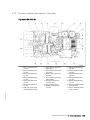
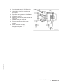
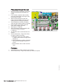
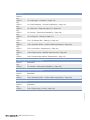
2.1.2
Engine layout
Also valid for 12V engines
1
2
3
4
5
6
Oil cooler
Coolant expansion tank
Crankcase breather
Air filter
Exhaust turbocharger
Intercooler
7
8
9
10
11
12
Cylinder head
Charge-air pipework
Oil filler neck
Oil pan
Engine mounting
HP fuel pump
13
14
15
16
Automatic oil filter
Fuel filter
Centrifugal oil filter(s)
Coolant cooler
Engine model designation
12, 16
Number of cylinders
V
Cylinder arrangement: V engine
4000
Series
M
Application
x
Application segment (1, 2 )
y
Design index (3)
z
R (reduced power/speed)
L (enhanced power/speed)
24 | Product Summary | MS150047/02E 2012-03
TIM-ID: 0000009991 - 004
Key to the engine model designations 16V 4000 Mxyz
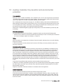
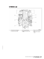
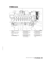
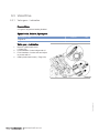
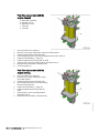
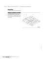
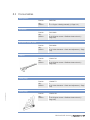
2.1.3
Sensors, actuators and injectors – Overview
Top view 12V 4000 M
8 B5.2 (lube oil pressure
after filter)
9 B34.2 (fuel pressure be‐
fore filter)
10 B34.1 (fuel pressure af‐
ter filter)
11 B5.3 (lube oil pressure
before filter)
12 B48 (fuel pressure in
common rail)
13 F33 (coolant level)
14 B4.B6 (exhaust temp.
cyl. B6)
15 B4.B5 (exhaust temp.
cyl. B5)
16 B4.B4 (exhaust temp.
cyl. B4)
17 B4.B3 (exhaust temp.
cyl. B3)
18 B4.B2 (exhaust temp.
cyl. B2)
19 B4.B1 (exhaust temp.
cyl. B1)
20 B4.22 (exhaust temper‐
ature, B bank)
21 B4.21 (exhaust temper‐
ature, A bank)
TIM-ID: 0000032308 - 001
1 B4.A1 (exhaust temp.
cyl. A1)
2 B4.A2 (exhaust temp.
cyl. A2)
3 B4.A3 (exhaust temp.
cyl. A3)
4 B4.A4 (exhaust temp.
cyl. A4)
5 B4.A5 (exhaust temp.
cyl. A5)
6 B4.A6 (exhaust temp.
cyl. A6)
7 B49 (charge-air temp.,
air recirculation valve)
MS150047/02E 2012-03 | Product Summary | 25
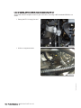
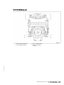
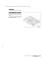
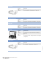
12V 4000 M left side
6 B10 (charge-air pres‐
sure)
7 B57.1 (main bearing
temp.)
8 B57.2 (main bearing
temp.)
9 B57.3 (main bearing
temp.)
10 B57.4 (main bearing
temp.)
11 B57.5 (main bearing
temp.)
12 B57.6 (main bearing
temp.)
13 B57.7 (main bearing
temp.)
TIM-ID: 0000032308 - 001
1 B5.1 (lube-oil pressure
after filter)
2 B7 (lube oil tempera‐
ture)
3 B50 (crankcase pres‐
sure)
4 B3 (intake air tempera‐
ture)
5 B44.1 (turbocharger A
speed)
26 | Product Summary | MS150047/02E 2012-03
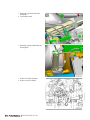
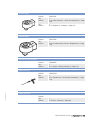
12V 4000 M free end
3 B1 (camshaft speed)
4 B54 (oil refill pump pres‐
sure)
5 B6.2 (coolant tempera‐
ture)
6 B6 (coolant tempera‐
ture)
TIM-ID: 0000032308 - 001
1 F46 (fuel level leakage)
2 B33 (fuel temp. (Rail)
MS150047/02E 2012-03 | Product Summary | 27
12V 4000 M right side
5 B77.B5 (spray oil temp.
(conrod bearing)
6 B77.B4 (spray oil temp.
(conrod bearing)
7 B77.B3 (spray oil temp.
(conrod bearing)
8 B77.B2 (spray oil temp.
(conrod bearing)
9 B77.B1 (spray oil temp.
(conrod bearing)
10 B9 (charge-air tempera‐
ture)
TIM-ID: 0000032308 - 001
1 B44.2 (turbocharger B
speed)
2 B16 (coolant pressure)
3 B21 (raw water pres‐
sure)
4 B77.B6 (spray oil temp.
(conrod bearing)
28 | Product Summary | MS150047/02E 2012-03
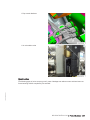
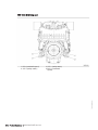
12 V 4000 M driving end
3 S37.1 (safety switch)
4 B13.2 (crankshaft
speed)
TIM-ID: 0000032308 - 001
1 B13 (crankshaft speed)
2 S37.2 (safety switch)
MS150047/02E 2012-03 | Product Summary | 29
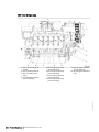
Top view 16V 4000 M
10 B4.A8 (exhaust temp.
cyl. A8)
11 B5.2 (P lube oil down‐
stream of filter)
12 B34.2 (fuel pressure be‐
fore filter)
13 B34.1 (fuel pressure af‐
ter filter)
14 B5.3 (lube oil pressure
before filter)
15 B48 (fuel pressure in
common rail)
16 F33 (coolant level)
17 B4.B8 (exhaust temp.
cyl. B8)
18 B4.B7 (exhaust temp.
cyl. B7)
19 B4.B6 (exhaust temp.
cyl. B6)
20 B4.B5 (exhaust temp.
cyl. B5)
21 B4.B4 (exhaust temp.
cyl. B4)
22 B4.B3 (exhaust temp.
cyl. B3)
23 B4.B2 (exhaust temp.
cyl. B2)
24 B4.B1 (exhaust temp.
cyl. B1)
25 B4.22 (exhaust temper‐
ature, B bank)
26 B4.21 (exhaust temper‐
ature, A bank)
TIM-ID: 0000032308 - 001
1 B4.A1 (exhaust temp.
cyl. A1)
2 B4.A2 (exhaust temp.
cyl. A2)
3 B4.A3 (exhaust temp.
cyl. A3)
4 B4.A4 (exhaust temp.
cyl. A4)
5 B4.A5 (exhaust temp.
cyl. A5)
6 B3 (intake air tempera‐
ture)
7 B4.A6 (exhaust temp.
cyl. A6)
8 B49 (charge-air temp.,
air recirculation valve)
9 B4.A7 (exhaust temp.
cyl. A7)
30 | Product Summary | MS150047/02E 2012-03
16V 4000 M left side
6 B57.1 (main bearing
temp.)
7 B57.2 (main bearing
temp.)
8 B57.3 (main bearing
temp.)
9 B57.4 (main bearing
temp.)
10 B57.5 (main bearing
temp.)
11 B57.6 (main bearing
temp.)
12 B57.7 (main bearing
temp.)
13 B57.8 (main bearing
temp.)
14 B57.9 (main bearing
temp.)
TIM-ID: 0000032308 - 001
1 B5.1 (lube-oil pressure
after filter)
2 B7 (lube oil tempera‐
ture)
3 B50 (crankcase pres‐
sure)
4 B44.1 (turbocharger A
speed)
5 B10 (charge-air pres‐
sure)
MS150047/02E 2012-03 | Product Summary | 31
16V 4000 M free end
3 B1 (camshaft speed)
4 B54 (oil refill pump pres‐
sure)
5 B6.2 (coolant tempera‐
ture)
6 B6 (coolant tempera‐
ture)
TIM-ID: 0000032308 - 001
1 F46 (fuel level leakage)
2 B33 (fuel temp. (Rail)
32 | Product Summary | MS150047/02E 2012-03
16V 4000 M right side
5 B77.B7 (spray oil temp.
(conrod bearing)
6 B77.B6 (spray oil temp.
(conrod bearing)
7 B77.B5 (spray oil temp.
(conrod bearing)
8 B77.B4 (spray oil temp.
(conrod bearing)
9 B77.B3 (spray oil temp.
(conrod bearing)
10 B77.B2 (spray oil temp.
(conrod bearing)
11 B77.B1 (spray oil temp.
(conrod bearing)
12 B9 (charge-air tempera‐
ture)
TIM-ID: 0000032308 - 001
1 B44.2 (turbocharger B
speed)
2 B16 (coolant pressure)
3 B21 (raw water pres‐
sure)
4 B77.B8 (spray oil temp.
(conrod bearing)
MS150047/02E 2012-03 | Product Summary | 33
16V 4000 M driving end
3 S37.1 (safety switch)
4 B13.2 (crankshaft
speed)
TIM-ID: 0000032308 - 001
1 B13 (crankshaft speed)
2 S37.2 (safety switch)
34 | Product Summary | MS150047/02E 2012-03
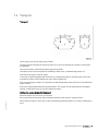
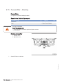
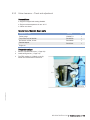
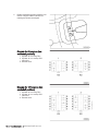
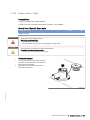
2.2 Engine side and cylinder designations
Engine sides are always designated as viewed from the driving end (KS).
The cylinders of the left engine side are designated with "A" and those of the right side with "B" (as per
DIN ISO 1204). The cylinders of each bank are numbered consecutively, starting with No. 1 at the en‐
gine's driving end.
Other components are numbered in the same way, i.e. starting with No. 1 at the engine's driving end.
3 KS = driving end
4 Left engine side
TIM-ID: 0000000863 - 018
1 KGS = free end
2 Right engine side
MS150047/02E 2012-03 | Product Summary | 35
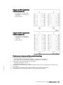
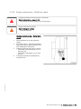
2.3 Engine – Main dimensions
Engine – Main dimensions
Length (A)
Width (B)
Height (C)
12V 4000 M73/93L
approx. 2991 mm
approx. 1463 mm
approx. 2368 mm
16V 4000 M73/93L
approx. 3583 mm
approx. 1463 mm
approx. 2368 mm
20V 4000 M73/93L
approx. 4192 mm
approx. 1484 mm
approx. 2368 mm
TIM-ID: 0000010044 - 002
Engine model
36 | Product Summary | MS150047/02E 2012-03
2.4 Firing order
Firing order
Firing order
8V
A1-B4-A4-A2-B3-A3-B2-B1
12V
A1-B5-A5-B3-A3-B6-A6-B2-A2-B4-A4-B1
16 V
A1-A7-B4-B6-A4-B8-A2-A8-B3-B5-A3-A5-B2-A6-B1-B7
20 V
A1-B5-A8-B7-A5-B2-A7-B10-A2-B3-A10-B6-A3-B4-A6-B9-A4-B1-A9-B8
TIM-ID: 0000002796 - 003
Num‐
ber of
cylin‐
ders
MS150047/02E 2012-03 | Product Summary | 37
2.5 Technical Data
2.5.1
ENGINE DATA 12V 4000M93, heat exchanger installed, EPA stage 2
Explanation:
DL
BL
A
G
R
L
N
X
Ref. value: Continuous power
Ref. value: Fuel stop power
Design value
Guaranteed value
Guideline value
Limit value, up to which the engine can be operated without changes (e.g. of power setting)
Not yet defined value
Not applicable
Applicable
REFERENCE CONDITIONS
Engine model
12V 4000
M93
Application group
1DS
Intake air temperature
°C
25
Raw water inlet temperature
°C
25
Barometric pressure
mbar
Site altitude above sea level
m
1000
100
POWER-RELATED DATA (power ratings are net brake power as per ISO 3046)
Number of cylinders
12
Rated engine speed
A
rpm
2100
Fuel stop power ISO 3046
A
kW
2340
GENERAL CONDITIONS (for maximum power)
Number of cylinders
12
Intake depression (new filter)
A
mbar
15
Intake depression, max.
L
mbar
30
MODEL RELATED DATA (basic design)
12
Cylinder arrangement: V angle
Degrees
90
Bore
mm
170
Stroke
mm
190
Displacement per cylinder
Liters
4.31
Displacement, total
Liters
51.72
Number of inlet valves per cylinder
2
Number of exhaust valves per cylinder
2
38 | Product Summary | MS150047/02E 2012-03
TIM-ID: 0000010927 - 001
Number of cylinders
RAW WATER CIRCUIT (open circuit)
Number of cylinders
12
Raw water pump: Inlet pressure, min.
L
bar
-0.2
Raw water pump: Inlet pressure , max.
L
bar
0.5
Pressure loss in external raw water system, max.
L
bar
0.7
LUBE OIL SYSTEM
Number of cylinders
12
Lube oil operating temperature before engine, from
R
°C
70*
Lube oil operating temperature before engine, to
R
°C
78*
Lube oil operating pressure before engine, from
R
bar
6
Lube oil operating pressure before engine, to
R
bar
8
Lube oil operating pressure, low idle (meas. point: before engine)
R
bar
2.0
FUEL SYSTEM
Number of cylinders
12
Fuel pressure at engine supply connection, min. (when engine is starting)
L
bar
-0.1
Fuel pressure at engine supply connection, min. (when engine is running)
L
bar
-0.3
Fuel pressure at engine supply connection, max. (when engine is starting)
L
bar
1.5
Fuel supply flow, max.
R
liter/min
30
GENERAL OPERATING DATA
Number of cylinders
12
Firing speed, from
R
rpm
80
Firing speed, to
R
rpm
120
STARTING (electric)
Number of cylinders
12
Starter, rated voltage (standard design)
R
V=
24
STARTING (with compressed air/hydraulic starter)
TIM-ID: 0000010927 - 001
Number of cylinders
12
Starting-air pressure before starter motor, min.
R
bar
8
Starting-air pressure before starter motor, max.
R
bar
10
INCLINATIONS, STANDARD OIL SYSTEM (reference: waterline)
Number of cylinders
12
Longitudinal inclination, continuous max., driving end down (option: max.
operating inclinations)
L
Degrees
15
Longitudinal inclination temporary max. drive side down (design: max. oper‐ L
ating inclinations)
Degrees
22.5
MS150047/02E 2012-03 | Product Summary | 39
Number of cylinders
12
Longitudinal inclination, continuous max., driving end up (option: max. oper‐ L
ating inclinations)
Degrees
10
Transverse inclination, constant max. (option: max. operating inclinations)
Degrees
22.5
L
CAPACITIES
Number of cylinders
Engine coolant, engine-side (with cooler)
12
R
Liters
360
Engine oil on initial filling (standard oil system) (option: max. operating incli‐ R
nations)
Liters
260
Oil change quantity, max. (standard oil system) (option: max. operating in‐
clinations)
R
Liters
205
Oil pan capacity at dipstick mark “min.” (standard oil system) (option: max.
operating inclinations)
L
Liters
160
Oil pan capacity at dipstick mark “max.” (standard oil system) (option: max.
operating inclinations)
L
Liters
200
WEIGHTS / MAIN DIMENSIONS
Number of cylinders
Engine dry weight (with attached standard accessories, without coupling)
12
R
kg
8010
ACOUSTICS
Number of cylinders
12
R
dB(A)
115
Engine surface noise with attenuated intake noise (filter), BL, (free-field
sound-pressure level Lp, 1m distance, ISO 6798, +2dB(A) tolerance)
R
dB(A)
104
TIM-ID: 0000010927 - 001
Exhaust noise, undamped - BL (free-field sound-pressure level Lp, 1m dis‐
tance, ISO 6798, +3dB(A) tolerance)
40 | Product Summary | MS150047/02E 2012-03
2.5.2
ENGINE DATA 12V 4000M93, heat exchanger installed, IMO
Explanation:
DL
BL
A
G
R
L
N
X
Ref. value: Continuous power
Ref. value: Fuel stop power
Design value
Guaranteed value
Guideline value
Limit value, up to which the engine can be operated without changes (e.g. of power setting)
Not yet defined value
Not applicable
Applicable
REFERENCE CONDITIONS
Engine model
12V 4000
M93
Application group
1DS
Intake air temperature
°C
25
Raw water inlet temperature
°C
25
Barometric pressure
mbar
Site altitude above sea level
m
1000
100
POWER-RELATED DATA (power ratings are net brake power as per ISO 3046)
Number of cylinders
12
Rated engine speed
A
rpm
2100
Fuel stop power ISO 3046
A
kW
2340
GENERAL CONDITIONS (for maximum power)
Number of cylinders
12
Intake depression (new filter)
A
mbar
15
Intake depression, max.
L
mbar
30
MODEL RELATED DATA (basic design)
TIM-ID: 0000010911 - 001
Number of cylinders
12
Cylinder arrangement: V angle
Degrees
90
Bore
mm
170
Stroke
mm
190
Displacement per cylinder
Liters
4.31
Displacement, total
Liters
51.72
Number of inlet valves per cylinder
2
Number of exhaust valves per cylinder
2
MS150047/02E 2012-03 | Product Summary | 41
RAW WATER CIRCUIT (open circuit)
Number of cylinders
12
Raw water pump: Inlet pressure, min.
L
bar
-0.2
Raw water pump: Inlet pressure , max.
L
bar
0.5
Pressure loss in external raw water system, max.
L
bar
0.7
LUBE OIL SYSTEM
Number of cylinders
12
Lube oil operating temperature before engine, from
R
°C
72*
Lube oil operating temperature before engine, to
R
°C
80*
Lube oil operating pressure before engine, from
R
bar
6
Lube oil operating pressure before engine, to
R
bar
8
Lube oil operating pressure, low idle (meas. point: before engine)
R
bar
2.0
FUEL SYSTEM
Number of cylinders
12
Fuel pressure at engine supply connection, min. (when engine is starting)
L
bar
-0.1
Fuel pressure at engine supply connection, min. (when engine is running)
L
bar
-0.3
Fuel pressure at engine supply connection, max. (when engine is starting)
L
bar
1.5
Fuel supply flow, max.
R
liter/min
30
GENERAL OPERATING DATA
Number of cylinders
12
Firing speed, from
R
rpm
80
Firing speed, to
R
rpm
120
STARTING (electric)
Number of cylinders
Starter, rated voltage (standard design)
12
R
V=
24
STARTING (with compressed air/hydraulic starter)
12
Starting-air pressure before starter motor, min.
R
bar
8
Starting-air pressure before starter motor, max.
R
bar
10
INCLINATIONS, STANDARD OIL SYSTEM (reference: waterline)
Number of cylinders
Longitudinal inclination, continuous max., driving end down (option: max.
operating inclinations)
12
L
Degrees
15
Longitudinal inclination temporary max. drive side down (design: max. oper‐ L
ating inclinations)
Degrees
22.5
42 | Product Summary | MS150047/02E 2012-03
TIM-ID: 0000010911 - 001
Number of cylinders
Number of cylinders
12
Longitudinal inclination, continuous max., driving end up (option: max. oper‐ L
ating inclinations)
Degrees
10
Transverse inclination, constant max. (option: max. operating inclinations)
Degrees
22.5
L
CAPACITIES
Number of cylinders
12
Engine coolant, engine-side (with cooler)
R
Liters
360
Engine oil on initial filling (standard oil system) (option: max. operating incli‐ R
nations)
Liters
260
Oil change quantity, max. (standard oil system) (option: max. operating in‐
clinations)
R
Liters
205
Oil pan capacity at dipstick mark “min.” (standard oil system) (option: max.
operating inclinations)
L
Liters
160
Oil pan capacity at dipstick mark “max.” (standard oil system) (option: max.
operating inclinations)
L
Liters
200
WEIGHTS / MAIN DIMENSIONS
Number of cylinders
12
Engine dry weight (with attached standard accessories, without coupling)
R
kg
8010
ACOUSTICS
Number of cylinders
12
R
dB(A)
115
Engine surface noise with attenuated intake noise (filter), BL, (free-field
sound-pressure level Lp, 1m distance, ISO 6798, +2dB(A) tolerance)
R
dB(A)
104
TIM-ID: 0000010911 - 001
Exhaust noise, undamped - BL (free-field sound-pressure level Lp, 1m dis‐
tance, ISO 6798, +3dB(A) tolerance)
MS150047/02E 2012-03 | Product Summary | 43
2.5.3
ENGINE DATA 12V 4000M93L, heat exchanger installed, EPA stage 2
Explanation:
DL
BL
A
G
R
L
N
X
Ref. value: Continuous power
Ref. value: Fuel stop power
Design value
Guaranteed value
Guideline value
Limit value, up to which the engine can be operated without changes (e.g. of power setting)
Not yet defined value
Not applicable
Applicable
REFERENCE CONDITIONS
Engine model
12V 4000
M93L
Application group
1DS
Intake air temperature
°C
25
Raw water inlet temperature
°C
25
Barometric pressure
mbar
Site altitude above sea level
m
1000
100
POWER-RELATED DATA (power ratings are net brake power as per ISO 3046)
Number of cylinders
12
Rated engine speed
A
rpm
2100
Fuel stop power ISO 3046
A
kW
2580
GENERAL CONDITIONS (for maximum power)
Number of cylinders
12
Intake depression (new filter)
A
mbar
15
Intake depression, max.
L
mbar
30
MODEL RELATED DATA (basic design)
12
Cylinder arrangement: V angle
Degrees
90
Bore
mm
170
Stroke
mm
190
Displacement per cylinder
Liters
4.31
Displacement, total
Liters
51.72
Number of inlet valves per cylinder
2
Number of exhaust valves per cylinder
2
44 | Product Summary | MS150047/02E 2012-03
TIM-ID: 0000010954 - 001
Number of cylinders
RAW WATER CIRCUIT (open circuit)
Number of cylinders
12
Raw water pump: Inlet pressure, min.
L
bar
-0.2
Raw water pump: Inlet pressure , max.
L
bar
0.5
Pressure loss in external raw water system, max.
L
bar
0.7
LUBE OIL SYSTEM
Number of cylinders
12
Lube oil operating temperature before engine, from
R
°C
72*
Lube oil operating temperature before engine, to
R
°C
80*
Lube oil operating pressure before engine, from
R
bar
6
Lube oil operating pressure before engine, to
R
bar
8
Lube oil operating pressure, low idle (meas. point: before engine)
R
bar
2.0
FUEL SYSTEM
Number of cylinders
12
Fuel pressure at engine supply connection, min. (when engine is starting)
L
bar
-0.1
Fuel pressure at engine supply connection, min. (when engine is running)
L
bar
-0.3
Fuel pressure at engine supply connection, max. (when engine is starting)
L
bar
1.5
Fuel supply flow, max.
R
liter/min
30
GENERAL OPERATING DATA
Number of cylinders
12
Firing speed, from
R
rpm
80
Firing speed, to
R
rpm
120
STARTING (electric)
Number of cylinders
12
Starter, rated voltage (standard design)
R
V=
24
STARTING (with compressed air/hydraulic starter)
TIM-ID: 0000010954 - 001
Number of cylinders
12
Starting-air pressure before starter motor, min.
R
bar
8
Starting-air pressure before starter motor, max.
R
bar
10
INCLINATIONS, STANDARD OIL SYSTEM (reference: waterline)
Number of cylinders
12
Longitudinal inclination, continuous max., driving end down (option: max.
operating inclinations)
L
Degrees
15
Longitudinal inclination temporary max. drive side down (design: max. oper‐ L
ating inclinations)
Degrees
22.5
MS150047/02E 2012-03 | Product Summary | 45
Number of cylinders
12
Longitudinal inclination, continuous max., driving end up (option: max. oper‐ L
ating inclinations)
Degrees
10
Transverse inclination, constant max. (option: max. operating inclinations)
Degrees
22.5
L
CAPACITIES
Number of cylinders
Engine coolant, engine-side (with cooler)
12
R
Liters
360
Engine oil on initial filling (standard oil system) (option: max. operating incli‐ R
nations)
Liters
260
Oil change quantity, max. (standard oil system) (option: max. operating in‐
clinations)
R
Liters
205
Oil pan capacity at dipstick mark “min.” (standard oil system) (option: max.
operating inclinations)
L
Liters
160
Oil pan capacity at dipstick mark “max.” (standard oil system) (option: max.
operating inclinations)
L
Liters
200
WEIGHTS / MAIN DIMENSIONS
Number of cylinders
Engine dry weight (with attached standard accessories, without coupling)
12
R
kg
8010
ACOUSTICS
Number of cylinders
12
R
dB(A)
116
Engine surface noise with attenuated intake noise (filter), BL, (free-field
sound-pressure level Lp, 1m distance, ISO 6798, +2dB(A) tolerance)
R
dB(A)
105
TIM-ID: 0000010954 - 001
Exhaust noise, undamped - BL (free-field sound-pressure level Lp, 1m dis‐
tance, ISO 6798, +3dB(A) tolerance)
46 | Product Summary | MS150047/02E 2012-03
2.5.4
ENGINE DATA 12V 4000M93L, heat exchanger installed, IMO
Explanation:
DL
BL
A
G
R
L
N
X
Ref. value: Continuous power
Ref. value: Fuel stop power
Design value
Guaranteed value
Guideline value
Limit value, up to which the engine can be operated without changes (e.g. of power setting)
Not yet defined value
Not applicable
Applicable
REFERENCE CONDITIONS
Engine model
12V 4000
M93L
Application group
1DS
Intake air temperature
°C
25
Raw water inlet temperature
°C
25
Barometric pressure
mbar
Site altitude above sea level
m
1000
100
POWER-RELATED DATA (power ratings are net brake power as per ISO 3046)
Number of cylinders
12
Rated engine speed
A
rpm
2100
Fuel stop power ISO 3046
A
kW
2580
GENERAL CONDITIONS (for maximum power)
Number of cylinders
12
Intake depression (new filter)
A
mbar
15
Intake depression, max.
L
mbar
30
MODEL RELATED DATA (basic design)
TIM-ID: 0000010940 - 001
Number of cylinders
12
Cylinder arrangement: V angle
Degrees
90
Bore
mm
170
Stroke
mm
190
Displacement per cylinder
Liters
4.31
Displacement, total
Liters
51.72
Number of inlet valves per cylinder
2
Number of exhaust valves per cylinder
2
MS150047/02E 2012-03 | Product Summary | 47
RAW WATER CIRCUIT (open circuit)
Number of cylinders
12
Raw water pump: Inlet pressure, min.
L
bar
-0.2
Raw water pump: Inlet pressure , max.
L
bar
0.5
Pressure loss in external raw water system, max.
L
bar
0.7
LUBE OIL SYSTEM
Number of cylinders
12
Lube oil operating temperature before engine, from
R
°C
72*
Lube oil operating temperature before engine, to
R
°C
80*
Lube oil operating pressure before engine, from
R
bar
6
Lube oil operating pressure before engine, to
R
bar
8
Lube oil operating pressure, low idle (meas. point: before engine)
R
bar
2.0
FUEL SYSTEM
Number of cylinders
12
Fuel pressure at engine supply connection, min. (when engine is starting)
L
bar
-0.1
Fuel pressure at engine supply connection, min. (when engine is running)
L
bar
-0.3
Fuel pressure at engine supply connection, max. (when engine is starting)
L
bar
1.5
Fuel supply flow, max.
R
liter/min
30
GENERAL OPERATING DATA
Number of cylinders
12
Firing speed, from
R
rpm
80
Firing speed, to
R
rpm
120
STARTING (electric)
Number of cylinders
Starter, rated voltage (standard design)
12
R
V=
24
STARTING (with compressed air/hydraulic starter)
12
Starting-air pressure before starter motor, min.
R
bar
8
Starting-air pressure before starter motor, max.
R
bar
10
INCLINATIONS, STANDARD OIL SYSTEM (reference: waterline)
Number of cylinders
Longitudinal inclination, continuous max., driving end down (option: max.
operating inclinations)
12
L
Degrees
15
Longitudinal inclination temporary max. drive side down (design: max. oper‐ L
ating inclinations)
Degrees
22.5
48 | Product Summary | MS150047/02E 2012-03
TIM-ID: 0000010940 - 001
Number of cylinders
Number of cylinders
12
Longitudinal inclination, continuous max., driving end up (option: max. oper‐ L
ating inclinations)
Degrees
10
Transverse inclination, constant max. (option: max. operating inclinations)
Degrees
22.5
L
CAPACITIES
Number of cylinders
12
Engine coolant, engine-side (with cooler)
R
Liters
360
Engine oil on initial filling (standard oil system) (option: max. operating incli‐ R
nations)
Liters
260
Oil change quantity, max. (standard oil system) (option: max. operating in‐
clinations)
R
Liters
205
Oil pan capacity at dipstick mark “min.” (standard oil system) (option: max.
operating inclinations)
L
Liters
160
Oil pan capacity at dipstick mark “max.” (standard oil system) (option: max.
operating inclinations)
L
Liters
200
WEIGHTS / MAIN DIMENSIONS
Number of cylinders
12
Engine dry weight (with attached standard accessories, without coupling)
R
kg
8010
ACOUSTICS
Number of cylinders
12
R
dB(A)
116
Engine surface noise with attenuated intake noise (filter), BL, (free-field
sound-pressure level Lp, 1m distance, ISO 6798, +2dB(A) tolerance)
R
dB(A)
105
TIM-ID: 0000010940 - 001
Exhaust noise, undamped - BL (free-field sound-pressure level Lp, 1m dis‐
tance, ISO 6798, +3dB(A) tolerance)
MS150047/02E 2012-03 | Product Summary | 49
2.5.5
ENGINE DATA 16V 4000M93, heat exchanger installed, EPA stage 2
Explanation:
DL
BL
A
G
R
L
N
X
Ref. value: Continuous power
Ref. value: Fuel stop power
Design value
Guaranteed value
Guideline value
Limit value, up to which the engine can be operated without changes (e.g. of power setting)
Not yet defined value
Not applicable
Applicable
REFERENCE CONDITIONS
Engine model
16V 4000
M93
Application group
1DS
Intake air temperature
°C
25
Raw water inlet temperature
°C
25
Barometric pressure
mbar
Site altitude above sea level
m
1000
100
POWER-RELATED DATA (power ratings are net brake power as per ISO 3046)
Number of cylinders
16
Rated engine speed
A
rpm
2100
Fuel stop power ISO 3046
A
kW
3120
GENERAL CONDITIONS (for maximum power)
Number of cylinders
16
Intake depression (new filter)
A
mbar
15
Intake depression, max.
L
mbar
30
MODEL RELATED DATA (basic design)
16
Cylinder arrangement: V angle
Degrees
90
Bore
mm
170
Stroke
mm
190
Displacement per cylinder
Liters
4.31
Displacement, total
Liters
68.96
Number of inlet valves per cylinder
2
Number of exhaust valves per cylinder
2
50 | Product Summary | MS150047/02E 2012-03
TIM-ID: 0000010971 - 001
Number of cylinders
RAW WATER CIRCUIT (open circuit)
Number of cylinders
16
Raw water pump: Inlet pressure, min.
L
bar
-0.2
Raw water pump: Inlet pressure , max.
L
bar
0.5
Pressure loss in external raw water system, max.
L
bar
0.7
LUBE OIL SYSTEM
Number of cylinders
16
Lube oil operating temperature before engine, from
R
°C
72*
Lube oil operating temperature before engine, to
R
°C
80*
Lube oil operating pressure before engine, from
R
bar
6
Lube oil operating pressure before engine, to
R
bar
8
Lube oil operating pressure, low idle (meas. point: before engine)
R
bar
2.0
FUEL SYSTEM
Number of cylinders
16
Fuel pressure at engine supply connection, min. (when engine is starting)
L
bar
-0.1
Fuel pressure at engine supply connection, min. (when engine is running)
L
bar
-0.3
Fuel pressure at engine supply connection, max. (when engine is starting)
L
bar
1.5
Fuel supply flow, max.
R
liter/min
30
GENERAL OPERATING DATA
Number of cylinders
16
Firing speed, from
R
rpm
80
Firing speed, to
R
rpm
120
STARTING (electric)
Number of cylinders
16
Starter, rated voltage (standard design)
R
V=
24
STARTING (with compressed air/hydraulic starter)
TIM-ID: 0000010971 - 001
Number of cylinders
16
Starting-air pressure before starter motor, min.
R
bar
8
Starting-air pressure before starter motor, max.
R
bar
10
INCLINATIONS, STANDARD OIL SYSTEM (reference: waterline)
Number of cylinders
16
Longitudinal inclination, continuous max., driving end down (option: max.
operating inclinations)
L
Degrees
15
Longitudinal inclination temporary max. drive side down (design: max. oper‐ L
ating inclinations)
Degrees
22.5
MS150047/02E 2012-03 | Product Summary | 51
Number of cylinders
16
Longitudinal inclination, continuous max., driving end up (option: max. oper‐ L
ating inclinations)
Degrees
10
Transverse inclination, constant max. (option: max. operating inclinations)
Degrees
22.5
L
CAPACITIES
Number of cylinders
16
R
Liters
540
Engine oil on initial filling (standard oil system) (option: max. operating incli‐ R
nations)
Liters
320
Oil change quantity, max. (standard oil system) (option: max. operating in‐
clinations)
R
Liters
270
Oil pan capacity at dipstick mark “min.” (standard oil system) (option: max.
operating inclinations)
L
Liters
215
Oil pan capacity at dipstick mark “max.” (standard oil system) (option: max.
operating inclinations)
L
Liters
260
Engine coolant, engine-side (with cooler)
WEIGHTS / MAIN DIMENSIONS
Number of cylinders
Engine dry weight (with attached standard accessories, without coupling)
16
R
kg
9600
ACOUSTICS
Number of cylinders
16
R
dB(A)
116
Engine surface noise with attenuated intake noise (filter), BL, (free-field
sound-pressure level Lp, 1m distance, ISO 6798, +2dB(A) tolerance)
R
dB(A)
105
TIM-ID: 0000010971 - 001
Exhaust noise, undamped - BL (free-field sound-pressure level Lp, 1m dis‐
tance, ISO 6798, +3dB(A) tolerance)
52 | Product Summary | MS150047/02E 2012-03
2.5.6
ENGINE DATA 16V 4000M93, heat exchanger installed, IMO
Explanation:
DL
BL
A
G
R
L
N
X
Ref. value: Continuous power
Ref. value: Fuel stop power
Design value
Guaranteed value
Guideline value
Limit value, up to which the engine can be operated without changes (e.g. of power setting)
Not yet defined value
Not applicable
Applicable
REFERENCE CONDITIONS
Engine model
16V 4000
M93
Application group
1DS
Intake air temperature
°C
25
Raw water inlet temperature
°C
25
Barometric pressure
mbar
Site altitude above sea level
m
1000
100
POWER-RELATED DATA (power ratings are net brake power as per ISO 3046)
Number of cylinders
16
Rated engine speed
A
rpm
2100
Fuel stop power ISO 3046
A
kW
3120
GENERAL CONDITIONS (for maximum power)
Number of cylinders
16
Intake depression (new filter)
A
mbar
15
Intake depression, max.
L
mbar
30
MODEL RELATED DATA (basic design)
TIM-ID: 0000010963 - 001
Number of cylinders
16
Cylinder arrangement: V angle
Degrees
90
Bore
mm
170
Stroke
mm
190
Displacement per cylinder
Liters
4.31
Displacement, total
Liters
68.96
Number of inlet valves per cylinder
2
Number of exhaust valves per cylinder
2
MS150047/02E 2012-03 | Product Summary | 53
RAW WATER CIRCUIT (open circuit)
Number of cylinders
16
Raw water pump: Inlet pressure, min.
L
bar
-0.2
Raw water pump: Inlet pressure , max.
L
bar
0.5
Pressure loss in external raw water system, max.
L
bar
0.7
LUBE OIL SYSTEM
Number of cylinders
16
Lube oil operating temperature before engine, from
R
°C
72*
Lube oil operating temperature before engine, to
R
°C
80*
Lube oil operating pressure before engine, from
R
bar
6
Lube oil operating pressure before engine, to
R
bar
8
Lube oil operating pressure, low idle (meas. point: before engine)
R
bar
2.0
FUEL SYSTEM
Number of cylinders
16
Fuel pressure at engine supply connection, min. (when engine is starting)
L
bar
-0.1
Fuel pressure at engine supply connection, min. (when engine is running)
L
bar
-0.3
Fuel pressure at engine supply connection, max. (when engine is starting)
L
bar
1.5
Fuel supply flow, max.
R
liter/min
30
GENERAL OPERATING DATA
Number of cylinders
16
Firing speed, from
R
rpm
80
Firing speed, to
R
rpm
120
STARTING (electric)
Number of cylinders
Starter, rated voltage (standard design)
16
R
V=
24
STARTING (with compressed air/hydraulic starter)
16
Starting-air pressure before starter motor, min.
R
bar
8
Starting-air pressure before starter motor, max.
R
bar
10
INCLINATIONS, STANDARD OIL SYSTEM (reference: waterline)
Number of cylinders
Longitudinal inclination, continuous max., driving end down (option: max.
operating inclinations)
16
L
Degrees
15
Longitudinal inclination temporary max. drive side down (design: max. oper‐ L
ating inclinations)
Degrees
22.5
54 | Product Summary | MS150047/02E 2012-03
TIM-ID: 0000010963 - 001
Number of cylinders
Number of cylinders
16
Longitudinal inclination, continuous max., driving end up (option: max. oper‐ L
ating inclinations)
Degrees
10
Transverse inclination, constant max. (option: max. operating inclinations)
Degrees
22.5
L
CAPACITIES
Number of cylinders
16
Engine coolant, engine-side (with cooler)
R
Liters
400
Engine oil on initial filling (standard oil system) (option: max. operating incli‐ R
nations)
Liters
320
Oil change quantity, max. (standard oil system) (option: max. operating in‐
clinations)
R
Liters
270
Oil pan capacity at dipstick mark “min.” (standard oil system) (option: max.
operating inclinations)
L
Liters
215
Oil pan capacity at dipstick mark “max.” (standard oil system) (option: max.
operating inclinations)
L
Liters
260
WEIGHTS / MAIN DIMENSIONS
Number of cylinders
16
Engine dry weight (with attached standard accessories, without coupling)
R
kg
9600
ACOUSTICS
Number of cylinders
16
R
dB(A)
116
Engine surface noise with attenuated intake noise (filter), BL, (free-field
sound-pressure level Lp, 1m distance, ISO 6798, +2dB(A) tolerance)
R
dB(A)
105
TIM-ID: 0000010963 - 001
Exhaust noise, undamped - BL (free-field sound-pressure level Lp, 1m dis‐
tance, ISO 6798, +3dB(A) tolerance)
MS150047/02E 2012-03 | Product Summary | 55
2.5.7
ENGINE DATA 16V 4000M93L, heat exchanger installed, EPA stage 2
Explanation:
DL
BL
A
G
R
L
N
X
Ref. value: Continuous power
Ref. value: Fuel stop power
Design value
Guaranteed value
Guideline value
Limit value, up to which the engine can be operated without changes (e.g. of power setting)
Not yet defined value
Not applicable
Applicable
REFERENCE CONDITIONS
Engine model
16V 4000
M93L
Application group
1DS
Intake air temperature
°C
25
Raw water inlet temperature
°C
25
Barometric pressure
mbar
Site altitude above sea level
m
1000
100
POWER-RELATED DATA (power ratings are net brake power as per ISO 3046)
Number of cylinders
16
Rated engine speed
A
rpm
2100
Fuel stop power ISO 3046
A
kW
3440
GENERAL CONDITIONS (for maximum power)
Number of cylinders
16
Intake depression (new filter)
A
mbar
15
Intake depression, max.
L
mbar
30
MODEL RELATED DATA (basic design)
16
Cylinder arrangement: V angle
Degrees
90
Bore
mm
170
Stroke
mm
190
Displacement per cylinder
Liters
4.31
Displacement, total
Liters
68.96
Number of inlet valves per cylinder
2
Number of exhaust valves per cylinder
2
56 | Product Summary | MS150047/02E 2012-03
TIM-ID: 0000010984 - 001
Number of cylinders
RAW WATER CIRCUIT (open circuit)
Number of cylinders
16
Raw water pump: Inlet pressure, min.
L
bar
-0.2
Raw water pump: Inlet pressure , max.
L
bar
0.5
Pressure loss in external raw water system, max.
L
bar
0.7
LUBE OIL SYSTEM
Number of cylinders
16
Lube oil operating temperature before engine, from
R
°C
72*
Lube oil operating temperature before engine, to
R
°C
80*
Lube oil operating pressure before engine, from
R
bar
6
Lube oil operating pressure before engine, to
R
bar
8
Lube oil operating pressure, low idle (meas. point: before engine)
R
bar
2.0
FUEL SYSTEM
Number of cylinders
16
Fuel pressure at engine supply connection, min. (when engine is starting)
L
bar
-0.1
Fuel pressure at engine supply connection, min. (when engine is running)
L
bar
-0.3
Fuel pressure at engine supply connection, max. (when engine is starting)
L
bar
1.5
Fuel supply flow, max.
R
liter/min
30
GENERAL OPERATING DATA
Number of cylinders
16
Firing speed, from
R
rpm
80
Firing speed, to
R
rpm
120
STARTING (electric)
Number of cylinders
16
Starter, rated voltage (standard design)
R
V=
24
STARTING (with compressed air/hydraulic starter)
TIM-ID: 0000010984 - 001
Number of cylinders
16
Starting-air pressure before starter motor, min.
R
bar
8
Starting-air pressure before starter motor, max.
R
bar
10
INCLINATIONS, STANDARD OIL SYSTEM (reference: waterline)
Number of cylinders
16
Longitudinal inclination, continuous max., driving end down (option: max.
operating inclinations)
L
Degrees
15
Longitudinal inclination temporary max. drive side down (design: max. oper‐ L
ating inclinations)
Degrees
22.5
MS150047/02E 2012-03 | Product Summary | 57
Number of cylinders
16
Longitudinal inclination, continuous max., driving end up (option: max. oper‐ L
ating inclinations)
Degrees
10
Transverse inclination, constant max. (option: max. operating inclinations)
Degrees
22.5
L
CAPACITIES
Number of cylinders
Engine coolant, engine-side (with cooler)
16
R
Liters
400
Engine oil on initial filling (standard oil system) (option: max. operating incli‐ R
nations)
Liters
320
Oil change quantity, max. (standard oil system) (option: max. operating in‐
clinations)
R
Liters
270
Oil pan capacity at dipstick mark “min.” (standard oil system) (option: max.
operating inclinations)
L
Liters
215
Oil pan capacity at dipstick mark “max.” (standard oil system) (option: max.
operating inclinations)
L
Liters
260
WEIGHTS / MAIN DIMENSIONS
Number of cylinders
Engine dry weight (with attached standard accessories, without coupling)
16
R
kg
9600
ACOUSTICS
Number of cylinders
16
R
dB(A)
117
Engine surface noise with attenuated intake noise (filter), BL, (free-field
sound-pressure level Lp, 1m distance, ISO 6798, +2dB(A) tolerance)
R
dB(A)
106
TIM-ID: 0000010984 - 001
Exhaust noise, undamped - BL (free-field sound-pressure level Lp, 1m dis‐
tance, ISO 6798, +3dB(A) tolerance)
58 | Product Summary | MS150047/02E 2012-03
2.5.8
ENGINE DATA 16V 4000M93L, heat exchanger installed, IMO
Explanation:
DL
BL
A
G
R
L
N
X
Ref. value: Continuous power
Ref. value: Fuel stop power
Design value
Guaranteed value
Guideline value
Limit value, up to which the engine can be operated without changes (e.g. of power setting)
Not yet defined value
Not applicable
Applicable
REFERENCE CONDITIONS
Engine model
16V 4000
M93L
Application group
1DS
Intake air temperature
°C
25
Raw water inlet temperature
°C
25
Barometric pressure
mbar
Site altitude above sea level
m
1000
100
POWER-RELATED DATA (power ratings are net brake power as per ISO 3046)
Number of cylinders
16
Rated engine speed
A
rpm
2100
Fuel stop power ISO 3046
A
kW
3440
GENERAL CONDITIONS (for maximum power)
Number of cylinders
16
Intake depression (new filter)
A
mbar
15
Intake depression, max.
L
mbar
30
MODEL RELATED DATA (basic design)
TIM-ID: 0000010978 - 001
Number of cylinders
16
Cylinder arrangement: V angle
Degrees
90
Bore
mm
170
Stroke
mm
190
Displacement per cylinder
Liters
4.31
Displacement, total
Liters
68.96
Number of inlet valves per cylinder
2
Number of exhaust valves per cylinder
2
MS150047/02E 2012-03 | Product Summary | 59
RAW WATER CIRCUIT (open circuit)
Number of cylinders
16
Raw water pump: Inlet pressure, min.
L
bar
-0.2
Raw water pump: Inlet pressure , max.
L
bar
0.5
Pressure loss in external raw water system, max.
L
bar
0.7
LUBE OIL SYSTEM
Number of cylinders
16
Lube oil operating temperature before engine, from
R
°C
72*
Lube oil operating temperature before engine, to
R
°C
80*
Lube oil operating pressure before engine, from
R
bar
6
Lube oil operating pressure before engine, to
R
bar
8
Lube oil operating pressure, low idle (meas. point: before engine)
R
bar
2.0
FUEL SYSTEM
Number of cylinders
16
Fuel pressure at engine supply connection, min. (when engine is starting)
L
bar
-0.1
Fuel pressure at engine supply connection, min. (when engine is running)
L
bar
-0.3
Fuel pressure at engine supply connection, max. (when engine is starting)
L
bar
1.5
Fuel supply flow, max.
R
liter/min
30
GENERAL OPERATING DATA
Number of cylinders
16
Firing speed, from
R
rpm
80
Firing speed, to
R
rpm
120
STARTING (electric)
Number of cylinders
Starter, rated voltage (standard design)
16
R
V=
24
STARTING (with compressed air/hydraulic starter)
16
Starting-air pressure before starter motor, min.
R
bar
8
Starting-air pressure before starter motor, max.
R
bar
10
INCLINATIONS, STANDARD OIL SYSTEM (reference: waterline)
Number of cylinders
Longitudinal inclination, continuous max., driving end down (option: max.
operating inclinations)
16
L
Degrees
15
Longitudinal inclination temporary max. drive side down (design: max. oper‐ L
ating inclinations)
Degrees
22.5
60 | Product Summary | MS150047/02E 2012-03
TIM-ID: 0000010978 - 001
Number of cylinders
Number of cylinders
16
Longitudinal inclination, continuous max., driving end up (option: max. oper‐ L
ating inclinations)
Degrees
10
Transverse inclination, constant max. (option: max. operating inclinations)
Degrees
22.5
L
CAPACITIES
Number of cylinders
16
Engine coolant, engine-side (with cooler)
R
Liters
400
Engine oil on initial filling (standard oil system) (option: max. operating incli‐ R
nations)
Liters
320
Oil change quantity, max. (standard oil system) (option: max. operating in‐
clinations)
R
Liters
270
Oil pan capacity at dipstick mark “min.” (standard oil system) (option: max.
operating inclinations)
L
Liters
215
Oil pan capacity at dipstick mark “max.” (standard oil system) (option: max.
operating inclinations)
L
Liters
260
WEIGHTS / MAIN DIMENSIONS
Number of cylinders
16
Engine dry weight (with attached standard accessories, without coupling)
R
kg
9600
ACOUSTICS
Number of cylinders
16
R
dB(A)
117
Engine surface noise with attenuated intake noise (filter), BL, (free-field
sound-pressure level Lp, 1m distance, ISO 6798, +2dB(A) tolerance)
R
dB(A)
106
TIM-ID: 0000010978 - 001
Exhaust noise, undamped - BL (free-field sound-pressure level Lp, 1m dis‐
tance, ISO 6798, +3dB(A) tolerance)
MS150047/02E 2012-03 | Product Summary | 61
3 Operation
3.1 LOP – Controls
Item
Color
Inscription
Meaning / Function
1
White
F1
2
White
F2
3
White
F3
Function keys to control the man-machine inter‐
face. Functions vary and are displayed on the
LCD screen.
4
White
F4
5
White
F5
6
White
ALARM ACKNOWL
Pressing the button the first time stops alarm sig‐
nalization.
Pressing the button a second time acknowledges
an active alarm.
LED (spot) lights up when an alarm is active.
7
White
62 | Operation | MS150047/02E 2012-03
DIM ↑
Holding down the button increases LCD back‐
ground illumination.
TIM-ID: 0000008861 - 002
LOP – Controls
Item
Color
Inscription
Meaning / Function
8
White
DIM ↓
Holding down the button decreases LCD back‐
ground illumination.
9
White
LAMP TEST
Pressing the button initiates lamp test.
10
Red
TEST OVERSPEED
Pressing the button initiates overspeed test.
LED (spot) lights up as long as the overspeed
test is running.
11
Green
(depending on type of
gearbox and propulsion)
FPP: Pressing the button engages gear ahead.
CPP, WJ, VS: Pressing the button engages
clutch.
LED (spot) lights up when GCU feedback is ac‐
tive.
12
Green
FPP, CPP, WJ, VS: Pressing the button disen‐
gages clutch.
LED (spot) lights up when GCU feedback is ac‐
tive.
13
Green
FPP: Pressing the button engages gear astern.
CPP, VS: No function assigned.
WJ: Holding down the button provides flushing of
water jet intake channel (water-jet reverse) .
LED (spot) lights up when GCU feedback is ac‐
tive.
14
White
ENGINE SPEED IN‐
CREASE
Engine speed is increased as long as the button
is held down.
15
White
ENGINE SPEED DE‐
CREASE
Engine speed is decreased as long as the button
is held down.
16
Green
READY FOR OPERA‐
TION
Pressing the button switches between "Not ready
for operation" and "Ready for operation".
LED (spot) is illuminated when the button is in the
"Ready for operation" position.
17
Green
LOCAL CONTROL
Pressing the button switches between local oper‐
ation and remote control.
LED (spot) lights up when local mode is active.
18
White
START
Pressing the button initiates the automatic engine
start sequence.
TIM-ID: 0000008861 - 002
LED (spot) lights up as long as the starting proce‐
dure is running.
19
White
STOP
Pressing the button initiates automatic engine
stopping procedure.
LED (spot) lights up as long as the STOP signal
is available (also if transmitted from RCS).
20
Red
EMERGENCY STOP
Pressing the button initiates an immediate emer‐
gency engine stop.
LED (spot) flashes once the emergency stop has
been tripped and until the alarm has been ac‐
knowledged.
MS150047/02E 2012-03 | Operation | 63
3.2 Putting the engine into operation after extended out-ofservice periods (>3 months)
Preconditions
☑ Engine is stopped and starting disabled.
☑ MTU Fluids and Lubricants Specifications (A001061/..) are available.
Putting into operation after long out-of-service periods (>3 months)
Item
Action
Engine
Depreserve (→ MTU Fluids and Lubricants Specifications A001061/..).
Lube oil system
Check engine oil level (→ Page 140);
Preheat engine oil if required.
Raw water pump (if located Fill with water (approx. 3 – 4 liters).
above waterline)
Coolant circuit
If engine is out of service for more than one year, change coolant
(→ Page 155).
Coolant circuit
Check coolant level (→ Page 154).
Coolant circuit
Heat coolant with coolant preheating unit.
Engine Control Unit
Check plug connections (→ Page 176).
HP fuel pump
Only for engines without oil priming pump
Fill HP fuel pump with new engine oil (→ Page 124)
Engine Control System
Switch master switch to ON;
Press illuminated pushbutton READY FOR OPERATION (→ Page 62).
Press illuminated pushbutton LAMP TEST (→ Page 62).
TIM-ID: 0000010093 - 004
LOP
64 | Operation | MS150047/02E 2012-03
3.3 Putting the engine into operation after scheduled out-ofservice-period
Preconditions
☑ Engine is stopped and starting disabled.
Putting into operation
Item
Action
Lube oil system
Check engine oil level (→ Page 140);
Preheat engine oil if required.
Coolant circuit
Check coolant level (→ Page 154).
Coolant circuit
Heat coolant with coolant preheating unit.
Engine Control System
Switch master switch to ON;
Press illuminated pushbutton READY FOR OPERATION (→ Page 62).
Press illuminated pushbutton LAMP TEST (→ Page 62).
TIM-ID: 0000010656 - 003
LOP
MS150047/02E 2012-03 | Operation | 65
3.4 Starting the engine
Preconditions
☑ External start interlock is not active.
☑ Emergency air shut-off flaps (if fitted) are open.
DANGER
WARNING
Unguarded rotating and moving engine components.
Risk of serious injury – danger to life!
• Before barring or starting the engine, make sure that nobody is in the danger zone.
Engine noise above 85 dB (A).
Risk of damage to hearing!
• Wear ear protectors.
The engine can be started from the following points
Item
Action
Control stand
(→ Operating instructions for electronic system)
Local Operating Panel LOP (→ Operating instructions for electronic system)
(→ Operating instructions for electronic system)
CCU
(→ Operating instructions for electronic system)
TIM-ID: 0000002240 - 003
Local Operation Station
LOS
66 | Operation | MS150047/02E 2012-03
3.5 Operational checks
DANGER
WARNING
Unguarded rotating and moving engine components.
Risk of serious injury – danger to life!
• Take special care when working on a running engine.
Engine noise above 85 dB (A).
Risk of damage to hearing!
• Wear ear protectors.
Operational checks
Item
Action
Engine oil
Check engine oil level (→ Page 140).
Engine under load,
Visually inspect engine for leaks and general condition;
engine at nominal speed
Check speed, pressures and temperatures;
Check engine and external lines for leaks;
Check for abnormal running noises and vibration;
Check exhaust color (→ Page 82).
Air filter
Check signal ring position of service indicator (→ Page 138);
Replace air filter (→ Page 136) if the signal ring is completely visible in the
service indicator observation window.
Intercooler
Check condensate drain(s) for water discharge and obstruction
(→ Page 135).
Exhaust gas system
Check condensate drain for obstructions.
Fuel prefilter(s)
Drain water and contamination from fuel prefilter (if fitted) (→ Page 78).
Check pointer position of differential pressure gage at fuel prefilter (if ap‐
plicable).
Check relief bore for oil and coolant discharge and contamination
(→ Page 159).
Raw water pump
Check relief bore for oil and water discharge and contamination
(→ Page 162).
TIM-ID: 0000010131 - 005
HT coolant pump
MS150047/02E 2012-03 | Operation | 67
3.6 Fuel treatment system control cabinet – Control elements
No.
Color
Caption
Meaning/Function
1
Green
Signal lamp
Indicates „Pump running“
2
Red
Signal lamp
Indicates „Pump fault“
3
Yellow
Illuminated but‐ Indicates „Water drain“ / Press to drain water manually.
ton
4
Red
Illuminated but‐ Indicates „Water alarm“ / Press to acknowledge.
ton
5
Yellow
Signal lamp
6
Red
Illuminated but‐ Indicates „Replace filter element“ / Press to acknowledge.
ton
Switch
Pump operating mode “Remote– 0 – Manual”
• Switch position “Remote”: Pump is controlled at LOP
• Switch position “0”: Pump is switched OFF
• Switch position “Manual”: Pump is started manually
Signal lamp
Indicates „Control voltage present”.
9
Hour meter
Indicates runtime of pump.
10
Master switch
8
White
68 | Operation | MS150047/02E 2012-03
TIM-ID: 0000015755 - 004
7
Indicates „Filter warning“ due to increased differential pressure.
3.7 Tasks after extended out-of-service periods (>3 weeks)
Tasks after extended out-of-service periods (>3 weeks)
Operate fuel treatment system for at least 5 minutes.
Start up fuel treatment system (→ Page 71).
Shut down fuel treatment system (→ Page 77).
TIM-ID: 0000007730 - 005
Note:
1.
2.
MS150047/02E 2012-03 | Operation | 69
3.8 Checks prior to start-up
Checks prior to start-up
1.
2.
3.
4.
5.
6.
Result:
TIM-ID: 0000007736 - 005
7.
Result:
Check tank and the entire pipework for cleanness. If microorganisms are detected:
a) Clean affected components.
b) Disinfect affected components with biocides (→ MTU Fluids and Lubricants Specifications
A001061/..).
Close drain valves on housing.
Open all supply and discharge valves.
Switch on fuel treatment system (→ Page 73).
Check direction of rotation of pump.
Vent bypass and fuel lines of the system.
a) Open ball valve for pressure tank.
b) Open ball valve for overflow tank.
c) Close ball valve at the inlet to the fuel treatment system.
Bypass line is vented via the overflow tank.
d) Open ball valve at the inlet to the fuel treatment system.
Check the fuel treatment system for leaks.
The fuel treatment system is ready for operation.
70 | Operation | MS150047/02E 2012-03
3.9 Fuel treatment system – Putting into operation
Overview of fuel treatment system
1
2
3
4
5
6
7
8
9
10
11
12
13
14
15
16
17
18
19
20
21
22
23
24
Pressure-free overflow
Bypass 1
Bypass 2
Safety valve, 3 bar
Ball valve, inlet
Pressure gage
Ventilation, sample extraction
Differential pressure gage
Ball valve, outlet
Check valve 700 mbar
Check valve 5 mbar
Return to overflow container
Engine
Overflow container
Water separator filter
Ball valve, drain
Automatic water drain
Water level electrode
Ball valve, sample extraction, inlet
Switchgear cabinet
Pump
Coarse filter
Fuel supply from tank
Tank
Switching on fuel treatment system
1.
2.
Result:
Switch on fuel treatment system (→ Page 73).
Check differential pressure at differential pressure gage (8). Differential pressure in a new system:
0.1 bar to 0.3 bar.
If no differential pressure is measured, the coalescer filter element is probably being bypassed.
1. Remove coalescer filter element (→ Page 172).
2. Check sealing surfaces on coalescer filter element and in the pressure tank.
Initial operation: HAT
1.
TIM-ID: 0000015773 - 005
Note:
2.
3.
Result:
4.
5.
6.
Note:
7.
8.
Result:
Replace fuel filter on engine (→ Page 131).
Determine the suction pressure upstream of the engine-mounted fuel delivery pump.
Install pressure gage in fuel supply line from Yard fuel system to engine.
Switch on fuel treatment system and operate it for some minutes (→ Page 73).
The fuel is drawn from tank (24), cleaned by the water separator filter (15) and then routed via overflow
tank (14) back to tank (24). Water that collects in the tank is separated.
Start engine (→ Page 66).
Run engine at idling speed.
Check suction pressure (see technical data of the engine) at the engine-mounted fuel delivery pump.
If the suction pressure is within the permissible limits and engine operation is satisfactory.
Increase engine speed to 1000 rpm and monitor suction pressure.
Check suction pressure at the engine-mounted fuel delivery pump.
If the values are within the limits specified by the manufacturer, the system is ready to start filter replace‐
ment simulation with the engine running as part of the Harbor Acceptance Tests.
MS150047/02E 2012-03 | Operation | 71
Simulation of filter replacement with the engine running: HAT
1.
2.
3.
4.
Result:
5.
Result:
6.
Note:
7.
Result:
Switch on fuel treatment system (→ Page 73).
Start engine (→ Page 66).
Run engine at idling speed.
Close ball valve (5) at inlet to fuel treatment system.
The pressure upstream of the fuel treatment system increases until the overflow valve at the pump unit
opens and fuel flows through bypass (3) and bypass (2).
Open ball valve (19) .
Fuel emerges. If no fuel emerges:
• Open ball valve (5) at inlet to fuel treatment system.
• No function of bypasses (2) and (3); carry out functional test of bypasses (2) and (3) .
Check suction pressure (see technical data of the engine) at the fuel delivery pump.
If the suction pressure is within the permissible limits and engine operation is satisfactory.
Increase engine speed to 1000 rpm and monitor suction pressure.
If all engine operating values are within the specified limits, open ball valve (5) at inlet to fuel treatment
system.
Simulation of power failure (emergency): HAT
1.
2.
3.
4.
Result:
5.
Switch on fuel treatment system (→ Page 73).
Start engine (→ Page 66).
Run engine at idling speed.
Switch off pump (21) on switchgear cabinet (20).
The engine-mounted fuel delivery pump draws fuel via bypass (2) directly from tank (24).
Check suction pressure at the engine-mounted fuel delivery pump.
Note:
6.
Result:
If the suction pressure is within the permissible limits and engine operation is satisfactory.
Increase engine speed to 1000 rpm and monitor suction pressure.
If the suction pressure is within the specified limits, simulation was successful.
Simulation of power failure (emergency): SAT
Switch on fuel treatment system (→ Page 73).
Start engine (→ Page 66).
Run engine at idling speed.
Switch off pump (21) at switchgear cabinet (20).
The engine-mounted fuel delivery pump draws fuel via bypass (2) directly from tank (24).
Check suction pressure at the engine-mounted fuel delivery pump.
Note:
6.
Result:
If the suction pressure is within the permissible limits and engine operation is satisfactory.
Operate engine at full load and monitor suction pressure.
If the suction pressure is within the specified limits, simulation was successful.
TIM-ID: 0000015773 - 005
1.
2.
3.
4.
Result:
5.
72 | Operation | MS150047/02E 2012-03
3.10 Fuel treatment system – Switching on
Preconditions
☑ The on-board power supply is switched on.
CAUTION
Damage to engine/plant.
Major material damage!
• Before switching on, ensure that the engine/plant is ready for operation.
• Before switching on, ensure that all housings are closed.
• Before switching on, ensure that no work is in progress anywhere on the entire system.
Switching on fuel treatment system
Carry out checks prior to start-up (→ Page 70).
Switch on master switch on switch cabinet.
Signal lamp “Control voltage present” lights up.
Switch on switch for pump.
Signal lamp “Pump running” lights up.
TIM-ID: 0000007731 - 005
1.
2.
Result:
3.
Result:
MS150047/02E 2012-03 | Operation | 73
3.11 Stopping the engine
Stopping the engine via the automation system
TIM-ID: 0000017528 - 004
Refer to automation system operating instructions
74 | Operation | MS150047/02E 2012-03
3.12 Emergency engine stop
CAUTION
An emergency stop causes extreme stress to the engine.
Risk of overheating, damage to components!
• Initiate emergency stop only in emergency situations.
Emergency stop
Refer to automation system operating instructions.
Follow instructions.
TIM-ID: 0000017530 - 004
1.
2.
MS150047/02E 2012-03 | Operation | 75
3.13 After stopping the engine
Preconditions
☑ MTU Fluids and Lubricants Specifications (A001061/..) are available.
After stopping the engine
Item
Action
Coolant circuit
Drain coolant (→ Page 156) if:
• freezing temperatures are expected and the engine is to remain out of
service for an extended period, but engine coolant has no antifreeze
additive;
• the engine room is not heated;
• the coolant is not kept at a suitable temperature;
• the antifreeze concentration is insufficient for the engine-room tempera‐
ture;
• antifreeze concentration is 50 % and engine-room temperature is below
-40 °C.
Raw water
Drain
• If freezing temperatures are to be expected and the engine is to remain
out of service for an extended period.
Engine control system
Switch off.
Air intake and exhaust sys‐ Out-of-service-period > 1 week
tem
• Seal engine's air and exhaust sides.
Out-of-service-period > 1 month
• Preserve engine (→ MTU Fluids and Lubricants Specifications
A001061/.. )
TIM-ID: 0000002324 - 007
Engine
76 | Operation | MS150047/02E 2012-03
3.14 Fuel treatment system – Shutdown
Shutting down fuel treatment system
1.
TIM-ID: 0000007732 - 005
2.
3.
4.
5.
Press the illuminated pushbutton "Water drain" on the switch cabinet until water discharge from the outlet
stops.
Switch off fuel treatment system.
Close ball valve at the inlet to the fuel treatment system.
Close ball valve at the outlet of the fuel treatment system.
Open drain valve until pressure has escaped from fuel treatment system.
MS150047/02E 2012-03 | Operation | 77
3.15 Fuel prefilter – Draining
Preconditions
☑ Engine is stopped and starting disabled.
Special tools, Material, Spare parts
Designation / Use
Diesel fuel
Seal
WARNING
Part No.
Qty.
(→ Spare Parts Catalog)
Fuels are combustible.
Risk of fire and explosion!
• Avoid open flames, electrical sparks and ignition sources.
• Do not smoke.
Draining fuel prefilter
I Left filter cut in
II Right filter cut in
Switch off filter to be drained.
TIM-ID: 0000019514 - 001
1.
78 | Operation | MS150047/02E 2012-03
2.
3.
4.
5.
6.
7.
8.
9.
TIM-ID: 0000019514 - 001
10.
11.
Open threaded vent plug (5) of filter to be
drained.
Unlock drain valve (6) by pressing toggle
and open it.
Drain water and contaminants from filter un‐
til pure fuel emerges.
Close drain valve (6).
Remove screws securing cover and take off
cover (2).
Fill filter housing with clean fuel.
Place new seal in cover (2).
Fit cover with seal and secure it with
screws.
Switch on cut-out filter again.
Close threaded vent plug (5) when fuel
emerges from system.
MS150047/02E 2012-03 | Operation | 79
3.16 Plant – Cleaning
Preconditions
☑ Engine is stopped and starting disabled.
☑ Operating voltage is not applied.
Special tools, Material, Spare parts
Designation / Use
Part No.
Qty.
Steam jet cleaner
-
1
30390
1
Cleaning agent (Hakupur 312)
WARNING
WARNING
CAUTION
NOTICE
Compressed air
Risk of injury!
• Do not direct compressed-air jet at persons.
• Wear protective goggles / safety mask and ear protectors.
Water jet.
Risk of injury and scalding!
• Do not direct water jet at persons.
• Wear protective clothing, gloves, and goggles / safety mask.
Excessive reaction time of cleaning agents on components.
Damage to component!
• Observe manufacturer's instructions.
• Wear protective clothing, gloves, and goggles / safety mask.
Dry with compressed air.
Damage to component!
• Never aim compressed air directly at electronic components.
1.
2.
3.
4.
Note:
5.
Carry out plant cleaning only in areas where an appropriate oil separator is provided (environmental pro‐
tection).
Prior to putting the cleaning unit into operation, read the Operating Instructions of the water/steam jet unit
carefully and observe the safety precautions.
For external cleaning with high-pressure jet, use a flat-mouth nozzle only.
Carry out external cleaning as follows:
a) Remove coarse dirt.
b) Spray on cleaner sparingly and leave it for 1 to 5 minutes.
c) Use the high-pressure jet to remove the loosened dirt.
d) During external cleaning of the plant with water/steam-jet units, the pressure of the high-pressure jet
(cleaning jet) must not exceed 50 bar. A minimum distance between spray nozzle and plant of 1 m
must be observed. The temperature of the cleaning medium must not exceed 80 °C.
Never aim compressed air directly at electronic components.
Dry engine.
80 | Operation | MS150047/02E 2012-03
TIM-ID: 0000010171 - 023
Plant – Cleaning
4 Maintenance
4.1 Maintenance schedule task reference table [QL1]
The maintenance tasks and intervals for this product are defined in the Maintenance Schedule. The
Maintenance Schedule is a stand-alone publication.
TIM-ID: 0000036097 - 001
The task numbers in this table provide reference to the maintenance tasks specified in the Maintenance
Schedule.
Task
Maintenance tasks
W0500
Check engine oil level
(→ Page 140)
W0501
Visually inspect engine for leaks and general condition
(→ Page 67)
W0502
Check intercooler drain(s)
(→ Page 135)
W0503
Check air filter maintenance indicator
(→ Page 138)
W0505
Check relief bores on coolant pump(s)
(→ Page 159)
W0506
Check engine for abnormal running noises, exhaust color
and vibrations
(→ Page 67)
W0507
Drain water and dirt from fuel prefilter (if applicable)
-
W0508
Check reading on differential pressure gage of fuel prefilter (if fitted)
W1001
Replace fuel filter or fuel filter element
(→ Page 131)
W1002
Check valve clearance
(→ Page 119)
W1005
Replace air filter
(→ Page 136)
W1006
Replace fuel injectors
(→ Page 125)
W1008
Replace engine oil filter at each oil change or when the time
limit (years) is reached, at the latest
-
W1009
Check layer thickness of oil residue, clean and replace filter
sleeve (if fitted) when the oil is changed at the latest
(→ Page 151)
W1011
Perform endoscopic inspection of combustion chambers
(→ Page 114)
W1016
Battery-charging generator: Check condition of coupling
-
W1029
Check air pipework between air filter and exhaust turbo‐
charger for leaks and damage
(→ Page 67)
W1036
Replace coolant filter
(→ Page 161)
W1047
Check and clean oil indicator filter
(→ Page 149)
W1076
Exhaust turbocharger: Clean compressor wheel
(→ Page 133)
W1244
Check operation of rod electrode (if applicable)
(→ Page 170)
W1245
Differential-pressure gage, check alarm function (if applica‐
ble)
(→ Page 169)
W1246
Check pump performance (if applicable)
(→ Page 171)
W1463
Check general condition of engine mounting (visual inspec‐
tion)
(→ Page 165)
W1487
Check intercooler for contamination
(→ Page 135)
Table 1: Maintenance schedule task reference table [QL1]
MS150047/02E 2012-03 | Maintenance | 81
5 Troubleshooting
5.1 Troubleshooting
Engine does not turn when starter is actuated
Component
Probable cause
Task
Battery
Low or defective
Charge or replace (see manufacturer's
documentation).
Cable connections defective
Check whether cable connections are
properly secured (see manufacturer's
documentation).
Starter
Engine wiring or starter defective
Check whether cable connections are
properly secured, contact Service.
Engine wiring
Defective
Check (→ Page 174).
LOP
Seating of assemblies or connectors
possibly loose
Inspect visually.
ECU
Plug-in connections possibly loose
Check plug connections (→ Page 176).
Engine
Running gear blocked (engine cannot
be barred manually)
Contact Service.
Engine turns on starting but does not fire
Component
Probable cause
Task
Starter
Poor rotation by starter: Battery low or
defective
Charge or replace battery (see manu‐
facturer's documentation).
Engine wiring
Defective
Check (→ Page 174).
ECU
Defective
Contact Service.
Engine fires unevenly
Component
Probable cause
Task
Fuel injection equip‐
ment
Injector defective
Replace (→ Page 125).
Engine wiring
Defective
Check (→ Page 174).
ECU
Defective
Contact Service.
Component
Probable cause
Task
Fuel supply
Easy-change fuel filter clogged
Replace (→ Page 131).
Air supply
Air filter clogged
Check signal ring position of service in‐
dicator (→ Page 138).
Fuel injection equip‐
ment
Injector defective
Replace (→ Page 125).
Engine wiring
Defective
Check (→ Page 174).
Engine
Overload
Contact Service.
82 | Troubleshooting | MS150047/02E 2012-03
TIM-ID: 0000010521 - 001
Engine does not reach rated speed
Engine speed not steady
Component
Probable cause
Task
Fuel injection equip‐
ment
Injector defective
Replace (→ Page 125).
Speed sensor
Defective
Contact Service.
ECU
Defective
Contact Service.
Charge-air temperature too high
Component
Probable cause
Task
Engine coolant
Incorrect engine coolant concentration
Check (MTU test kit).
Intercooler
Contaminated
Contact Service.
Engine room
Air-intake temperature too high
Check fans and air supply / ventilation
ducts.
Charge-air pressure too low
Component
Probable cause
Task
Air supply
Air filter clogged
Check signal ring position of service in‐
dicator (→ Page 138).
Intercooler
Contaminated
Contact Service.
Exhaust turbocharger Defective
Contact Service.
Coolant leaks on intercooler
Component
Probable cause
Task
Intercooler
Leaking, major coolant discharge
Contact Service.
Component
Probable cause
Task
Air supply
Air filter clogged
Check signal ring position of service in‐
dicator (→ Page 138).
Fuel injection equip‐
ment
Injector defective
Replace (→ Page 125).
Engine
Overload
Contact Service.
Component
Probable cause
Task
Engine oil
Too much oil in engine
Drain engine oil (→ Page 141).
Oil separator or oil preseparator of
crankcase breather clogged
Replace.
Exhaust gas black
TIM-ID: 0000010521 - 001
Exhaust gas blue
Exhaust turbocharg‐ Defective
er, cylinder head, pis‐
ton rings, cylinder lin‐
er
Contact Service.
MS150047/02E 2012-03 | Troubleshooting | 83
Exhaust gas white
Probable cause
Task
Engine
Not at operating temperature
Run engine to reach operating temper‐
ature.
Intercooler
Leaking
Contact Service.
TIM-ID: 0000010521 - 001
Component
84 | Troubleshooting | MS150047/02E 2012-03
5.2 Fuel treatment system – Troubleshooting
Illuminated pushbutton “Water alarm” is lit.
Cause
Corrective action
When the maximum water level
is reached, the water level elec‐
trode opens the water drain
valve and water is discharged. If
the opening period of the valve
exceeds a preset limit (4 mi‐
nutes), the pump will switch off
and an alarm is initiated.
1. Press illuminated pushbutton “Water alarm” to acknowledge.
2. In addition to the automatic water drain function, water can also
be drained manually. To do so, press the illuminated pushbutton
“Water drain” to open the drain valve.
Signal lamp “Pump fault” is lit.
Cause
The drive motor is equipped with
an overload protection. If the
maximum permissible current
consumption is exceeded, e.g. in
case of a blockage or dry-run‐
ning, the motor protection relay
triggers and the pump is switch‐
ed off.
Corrective action
u Reset motor protection relay.
Signal lamp “Warning filter” is lit.
Cause
The differential pressure exceed‐
ed 1.3 bar.
Corrective action
u Replace coalescer filter element (→ Page 172).
Illuminated pushbutton “Replace filter element” is lit.
TIM-ID: 0000031170 - 001
Cause
The max. permissible differential
pressure of 1.5 bar was exceed‐
ed. If the coalescer filter element
is not replaced, pressure will in‐
crease further and the safety
valve will open. Fuel will be led
via the bypass directly into the
overflow tank.
Corrective action
1. Replace coalescer filter element (→ Page 172).
2. Press illuminated pushbutton “Replace filter element” to ac‐
knowledge.
MS150047/02E 2012-03 | Troubleshooting | 85
5.3 ADEC engine governor – Fault codes
29 – HI ETC Idle Speed too High
ZKP-Number: 18.004.206
Cause
Corrective action
Idle speed of one of the
secondary turbochargers is too
high.
u Contact Service.
38 – AL ETC Speed Deviation
ZKP-Number: 18.004.205
Cause
Speed of one of the secondary
turbochargers deviates from
primary turbocharger speed.
Corrective action
1. Reduce power.
2. Contact Service.
39 – AL ETC2 CutIn Failure
ZKP-Number: 18.004.204
Cause
ETC2 could not be cut in.
Corrective action
1. Reduce power.
2. Contact Service.
81 – AL Rail Leakage
ZKP-Number: 18.004.046
Cause
Pressure gradient in rail is too
low during starting or too high
during stopping (HP system
leaky or air in the system)
Corrective action
u Contact Service.
102 – AL Cons. Counter Defect
ZKP-Number: 18.004.624
Consumption meter faulty.
Corrective action
u Contact Service.
104 – AL Eng Hours Counter Defect
ZKP-Number: 18.004.623
Cause
Hour meter faulty.
86 | Troubleshooting | MS150047/02E 2012-03
Corrective action
u Contact Service.
TIM-ID: 0000018389 - 002
Cause
141 – AL Power too high
ZKP-Number: 11.088.007
Cause
This alarm occurs if the average
value of power over the last 24
hours exceeded the maximum
value specified in PR1.1088.001.
Corrective action
u Reduce power.
142 – AL MCR exceeded 1 hour
ZKP-Number: 11.088.006
Cause
This alarm occurs if the MCR
was exceeded for more than 1
hour within the last 12 hours.
Corrective action
u Reduce power.
201 – SD T-Coolant
ZKP-Number: 18.004.570
Cause
Coolant temperature sensor
faulty; Short circuit or wire break
Corrective action
1. Check sensor and cabling (B6), replace as necessary.
2. Error cleared after restarting the engine.
202 – SD T-Fuel
ZKP-Number: 18.004.572
Cause
Coolant temperature sensor
faulty; Short circuit or wire break
Corrective action
1. Check sensor and cabling (B33), replace as necessary.
2. Error cleared after restarting the engine.
203 – SD T-Charge Air
ZKP-Number: 18.004.571
Cause
Charge-air temperature sensor
faulty; Short circuit or wire break
Corrective action
1. Check sensor and cabling (B9), replace as necessary.
2. Error cleared after restarting the engine.
TIM-ID: 0000018389 - 002
204 – SD Level Lube Oil
ZKP-Number: 18.004.602
Cause
Lube oil level sensor defective;
Short circuit or wire break
Corrective action
u Check sensor and cabling, replace as necessary.
MS150047/02E 2012-03 | Troubleshooting | 87
205 – SD T-Coolant Intercooler
ZKP-Number: 18.004.574
Cause
Intercooler coolant temperature
sensor faulty; Short circuit or
wire break
Corrective action
u Check sensor and cabling (B26), replace as necessary.
206 – SD T-Exhaust A
ZKP-Number: 18.004.576
Cause
Exhaust temperature sensor on
A-side faulty; Short circuit or wire
break
Corrective action
u Check sensor and cabling (B4.21), replace as necessary.
207 – SD T-Exhaust B
ZKP-Number: 18.004.577
Cause
Exhaust temperature sensor on
B-side faulty; Short circuit or wire
break
Corrective action
u Check sensor and cabling (B4.22), replace as necessary.
208 – SD P-Charge Air
ZKP-Number: 18.004.566
Cause
Charge-air pressure sensor
faulty; Short circuit or wire break
Corrective action
1. Check sensor and cabling (B10), replace as necessary.
2. Error cleared after restarting the engine.
211 – SD P-Lube Oil
ZKP-Number: 18.004.563
Cause
Lube oil pressure sensor faulty;
Short circuit or wire break
Corrective action
1. Check sensor and cabling (B5), replace as necessary.
2. Error cleared after restarting the engine.
ZKP-Number: 18.004.564
Cause
Coolant pressure sensor faulty;
Short circuit or wire break
88 | Troubleshooting | MS150047/02E 2012-03
Corrective action
1. Check sensor and cabling (B16), replace as necessary.
2. Error cleared after restarting the engine.
TIM-ID: 0000018389 - 002
212 – SD P-Coolant
213 – SD P-Coolant Intercooler
ZKP-Number: 18.004.569
Cause
Corrective action
Intercooler coolant pressure
sensor faulty; Short circuit or
wire break
1. Check sensor and cabling (B43), replace as necessary.
2. Error cleared after restarting the engine.
214 – SD P-Crankcase
ZKP-Number: 18.004.568
Cause
Corrective action
Crankcase pressure sensor
faulty; Short circuit or wire break
1. Check sensor and cabling (B50), replace as necessary.
2. Error cleared after restarting the engine.
215 – SD P-HD
ZKP-Number: 18.004.567
Cause
Corrective action
Rail pressure sensor faulty;
High-pressure regulator
emergency mode; Short circuit
or wire break
1. Check sensor and cabling (B48), replace as necessary.
2. Error cleared after restarting the engine.
216 – SD T-Lube Oil
ZKP-Number: 18.004.575
Cause
Corrective action
Lube oil temperature sensor
faulty; Short circuit or wire break
1. Check sensor and cabling (B7), replace as necessary.
2. Error cleared after restarting the engine.
219 – SD T-Intake Air
ZKP-Number: 18.004.573
Cause
Corrective action
Intake air temperature sensor
faulty; Short circuit or wire break
1. Check sensor and cabling (B3), replace as necessary.
2. Error cleared after restarting the engine.
TIM-ID: 0000018389 - 002
220 – SD Level Coolant Water
ZKP-Number: 18.004.584
Cause
Coolant level sensor faulty; Short
circuit or wire break
Corrective action
1. Check sensor and cabling (F33), replace as necessary.
2. Error cleared after restarting the engine.
MS150047/02E 2012-03 | Troubleshooting | 89
221 – SD P-Diff-Lube Oil
ZKP-Number: 18.004.585
Cause
Corrective action
Lube oil differential pressure
sensor faulty; Short circuit or
wire break
1. Check sensor and cabling (F25), replace as necessary.
2. Error cleared after restarting the engine.
222 – SD Level Leakage Fuel
ZKP-Number: 18.004.582
Cause
Corrective action
Leak-off fuel level sensor faulty;
Short circuit or wire break
1. Check sensor and cabling (F46), replace as necessary.
2. Error cleared after restarting the engine.
223 – SD Level Coolant Intercooler
ZKP-Number: 18.004.583
Cause
Corrective action
Coolant level sensor of
intercooler faulty; Short circuit or
wire break
1. Check sensor and cabling (F57), replace as necessary.
2. Error cleared after restarting the engine.
227 – SD P-Lube Oil before Filter
ZKP-Number: 18.004.620
Cause
Corrective action
Sensor for lube oil pressure
before filter faulty; Short circuit or
wire break
1. Check sensor and cabling (B5.3), replace as necessary.
2. Error cleared after restarting the engine.
228 – SD P-Fuel before Filter
ZKP-Number: 18.004.595
Cause
Fuel pressure sensor faulty;
Short circuit or wire break
Corrective action
1. Check sensor and cabling (B5.3), replace as necessary.
2. Error cleared after restarting the engine.
ZKP-Number: 18.004.562
Cause
Engine shutdown due to
camshaft sensor fault (and a
prior crankshaft sensor fault in
the same operating cycle).
90 | Troubleshooting | MS150047/02E 2012-03
Corrective action
1. Check sensor and cabling to connector B1, replace as
necessary.
2. Error cleared after restarting the engine.
TIM-ID: 0000018389 - 002
229 – AL Stop Camshaft Sensor Defect
230 – SD Crankshaft Speed
ZKP-Number: 18.004.498
Cause
Crankshaft sensor faulty; Short
circuit or wire break
Corrective action
1. Check sensor and cabling (B13), replace as necessary.
2. Error cleared after restarting the engine.
231 – SD Camshaft Speed
ZKP-Number: 18.004.499
Cause
Camshaft sensor faulty; Short
circuit or wire break
Corrective action
1. Check sensor and cabling (B1), replace as necessary.
2. Error cleared after restarting the engine.
232 – SD Charger 1 Speed
ZKP-Number: 13.011.128
Cause
Speed sensor of primary
turbocharger faulty; Short circuit
or wire break
Corrective action
1. Check sensor and cabling (B44.1), replace as necessary.
2. Error cleared after restarting the engine.
233 – SD Charger 2 Speed
ZKP-Number: 13.011.129
Cause
Speed sensor of secondary
turbocharger faulty; Short circuit
or wire break
Corrective action
1. Check sensor and cabling (B44.2), replace as necessary.
2. Error cleared after restarting the engine.
239 – SD P-Diff Fuel
ZKP-Number: 18.004.598
Cause
TIM-ID: 0000018389 - 002
Fuel differential pressure sensor
faulty; occurs only in
combination with alarm "SD PFuel before Filter" or "SD P-Fuel
after Filter".
Corrective action
u Note further fault messages.Pressure sensor before or after filter
is faulty.
240 – SD P-Fuel
ZKP-Number: 18.004.565
Cause
Fuel pressure sensor faulty;
Short circuit or wire break
Corrective action
1. Check sensor and cabling (B34), replace as necessary.
2. Error cleared after restarting the engine.
MS150047/02E 2012-03 | Troubleshooting | 91
241 – SD T-Umblasen
ZKP-Number: 18.004.581
Cause
Recirculation temperature
sensor faulty; Short circuit or
wire break
Corrective action
1. Check sensor and cabling (B49), replace as necessary.
2. Error cleared after restarting the engine.
242 – SD T-Coolant (R)
ZKP-Number: 18.004.622
Cause
Redundant coolant temperature
sensor faulty; Short circuit or
wire break
Corrective action
1. Check sensor and cabling, replace as necessary.
2. Error cleared after restarting the engine.
244 – SD P-Lube Oil (R)
ZKP-Number: 18.004.621
Cause
Redundant lube oil pressure
sensor faulty; Short circuit or
wire break
Corrective action
1. Check sensor and cabling, replace as necessary.
2. Error cleared after restarting the engine.
301 – AL Timing Cylinder A1
ZKP-Number: 18.004.500
Cause
Time-of-flight measuring fault of
injector in cylinder A1: Time-of
flight measured value extremely
low or extremely high.
Corrective action
u If alarm occurs frequently, replace solenoid valve of injector
302 – AL Timing Cylinder A2
ZKP-Number: 18.004.501
Time-of-flight measuring fault of
injector in cylinder A2: Time-of
flight measured value extremely
low or extremely high.
92 | Troubleshooting | MS150047/02E 2012-03
Corrective action
u If alarm occurs frequently, replace solenoid valve of injector
TIM-ID: 0000018389 - 002
Cause
303 – AL Timing Cylinder A3
ZKP-Number: 18.004.502
Cause
Time-of-flight measuring fault of
injector in cylinder A3: Time-of
flight measured value extremely
low or extremely high.
Corrective action
u If alarm occurs frequently, replace solenoid valve of injector
304 – AL Timing Cylinder A4
ZKP-Number: 18.004.503
Cause
Time-of-flight measuring fault of
injector in cylinder A4: Time-of
flight measured value extremely
low or extremely high.
Corrective action
u If alarm occurs frequently, replace solenoid valve of injector
305 – AL Timing Cylinder A5
ZKP-Number: 18.004.504
Cause
Time-of-flight measuring fault of
injector in cylinder A5: Time-of
flight measured value extremely
low or extremely high.
Corrective action
u If alarm occurs frequently, replace solenoid valve of injector
306 – AL Timing Cylinder A6
ZKP-Number: 18.004.505
Cause
Time-of-flight measuring fault of
injector in cylinder A6: Time-of
flight measured value extremely
low or extremely high.
Corrective action
u If alarm occurs frequently, replace solenoid valve of injector
307 – AL Timing Cylinder A7
ZKP-Number: 18.004.506
TIM-ID: 0000018389 - 002
Cause
Time-of-flight measuring fault of
injector in cylinder A7: Time-of
flight measured value extremely
low or extremely high.
Corrective action
u If alarm occurs frequently, replace solenoid valve of injector
MS150047/02E 2012-03 | Troubleshooting | 93
308 – AL Timing Cylinder A8
ZKP-Number: 18.004.507
Cause
Corrective action
Time-of-flight measuring fault of
injector in cylinder A8: Time-of
flight measured value extremely
low or extremely high.
u If alarm occurs frequently, replace solenoid valve of injector
309 – AL Timing Cylinder A9
ZKP-Number: 18.004.508
Cause
Corrective action
Time-of-flight measuring fault of
injector in cylinder A9: Time-of
flight measured value extremely
low or extremely high.
u If alarm occurs frequently, replace solenoid valve of injector
310 – AL Timing Cylinder A10
ZKP-Number: 18.004.509
Cause
Time-of-flight measuring fault of
injector in cylinder A10: Time-of
flight measured value extremely
low or extremely high.
Corrective action
u If alarm occurs frequently, replace solenoid valve of injector
311 – AL Timing Cylinder B1
ZKP-Number: 18.004.510
Cause
Time-of-flight measuring fault of
injector B1: Time-of flight
measured value extremely low or
extremely high.
Corrective action
u If alarm occurs frequently, replace solenoid valve of injector
312 – AL Timing Cylinder B2
ZKP-Number: 18.004.511
Time-of-flight measuring fault of
injector B2: Time-of flight
measured value extremely low or
extremely high.
94 | Troubleshooting | MS150047/02E 2012-03
Corrective action
u If alarm occurs frequently, replace solenoid valve of injector
TIM-ID: 0000018389 - 002
Cause
313 – AL Timing Cylinder B3
ZKP-Number: 18.004.512
Cause
Time-of-flight measuring fault of
injector B3: Time-of flight
measured value extremely low or
extremely high.
Corrective action
u If alarm occurs frequently, replace solenoid valve of injector
314 – AL Timing Cylinder B4
ZKP-Number: 18.004.513
Cause
Time-of-flight measuring fault of
injector B4: Time-of flight
measured value extremely low or
extremely high.
Corrective action
u If alarm occurs frequently, replace solenoid valve of injector
315 – AL Timing Cylinder B5
ZKP-Number: 18.004.514
Cause
Time-of-flight measuring fault of
injector B5: Time-of flight
measured value extremely low or
extremely high.
Corrective action
u If alarm occurs frequently, replace solenoid valve of injector
316 – AL Timing Cylinder B6
ZKP-Number: 18.004.515
Cause
Time-of-flight measuring fault of
injector B6: Time-of flight
measured value extremely low or
extremely high.
Corrective action
u If alarm occurs frequently, replace solenoid valve of injector
317 – AL Timing Cylinder B7
ZKP-Number: 18.004.516
TIM-ID: 0000018389 - 002
Cause
Time-of-flight measuring fault of
injector B7: Time-of flight
measured value extremely low or
extremely high.
Corrective action
u If alarm occurs frequently, replace solenoid valve of injector
MS150047/02E 2012-03 | Troubleshooting | 95
318 – AL Timing Cylinder B8
ZKP-Number: 18.004.517
Cause
Corrective action
Time-of-flight measuring fault of
injector B8: Time-of flight
measured value extremely low or
extremely high.
u If alarm occurs frequently, replace solenoid valve of injector
319 – AL Timing Cylinder B9
ZKP-Number: 18.004.518
Cause
Corrective action
Time-of-flight measuring fault of
injector B9: Time-of flight
measured value extremely low or
extremely high.
u If alarm occurs frequently, replace solenoid valve of injector
320 – AL Timing Cylinder B10
ZKP-Number: 18.004.519
Cause
Time-of-flight measuring fault of
injector B10: Time-of flight
measured value extremely low or
extremely high.
Corrective action
u If alarm occurs frequently, replace solenoid valve of injector
321 – AL Wiring Cylinder A1
ZKP-Number: 18.004.520
Cause
Short-circuit in injector cabling to
cylinder A1. Result: Misfiring.
Corrective action
1. Rectify short circuit in injector solenoid valve circuit (positive to
negative) (e.g. by injector replacement)
2. Error cleared after restarting the engine.
322 – AL Wiring Cylinder A2
ZKP-Number: 18.004.521
Short-circuit in injector cabling to
cylinder A2. Result: Misfiring.
96 | Troubleshooting | MS150047/02E 2012-03
Corrective action
1. Rectify short circuit in injector solenoid valve circuit (positive to
negative) (e.g. by injector replacement)
2. Error cleared after restarting the engine.
TIM-ID: 0000018389 - 002
Cause
323 – AL Wiring Cylinder A3
ZKP-Number: 18.004.522
Cause
Short-circuit in injector cabling to
cylinder A3. Result: Misfiring.
Corrective action
1. Rectify short circuit in injector solenoid valve circuit (positive to
negative) (e.g. by injector replacement)
2. Error cleared after restarting the engine.
324 – AL Wiring Cylinder A4
ZKP-Number: 18.004.523
Cause
Short-circuit in injector cabling to
cylinder A4. Result: Misfiring.
Corrective action
1. Rectify short circuit in injector solenoid valve circuit (positive to
negative) (e.g. by injector replacement)
2. Error cleared after restarting the engine.
325 – AL Wiring Cylinder A5
ZKP-Number: 18.004.524
Cause
Short-circuit in injector cabling to
cylinder A5. Result: Misfiring.
Corrective action
1. Rectify short circuit in injector solenoid valve circuit (positive to
negative) (e.g. by injector replacement)
2. Error cleared after restarting the engine.
326 – AL Wiring Cylinder A6
ZKP-Number: 18.004.525
Cause
Short-circuit in injector cabling to
cylinder A6. Result: Misfiring.
Corrective action
1. Rectify short circuit in injector solenoid valve circuit (positive to
negative) (e.g. by injector replacement)
2. Error cleared after restarting the engine.
327 – AL Wiring Cylinder A7
ZKP-Number: 18.004.526
Cause
TIM-ID: 0000018389 - 002
Short-circuit in injector cabling to
cylinder A7. Result: Misfiring.
Corrective action
1. Rectify short circuit in injector solenoid valve circuit (positive to
negative) (e.g. by injector replacement)
2. Error cleared after restarting the engine.
328 – AL Wiring Cylinder A8
ZKP-Number: 18.004.527
Cause
Short-circuit in injector cabling to
cylinder A8. Result: Misfiring.
Corrective action
1. Rectify short circuit in injector solenoid valve circuit (positive to
negative) (e.g. by injector replacement)
2. Error cleared after restarting the engine.
MS150047/02E 2012-03 | Troubleshooting | 97
329 – AL Wiring Cylinder A9
ZKP-Number: 18.004.528
Cause
Corrective action
Short-circuit in injector cabling to
cylinder A9. Result: Misfiring.
1. Rectify short circuit in injector solenoid valve circuit (positive to
negative) (e.g. by injector replacement)
2. Error cleared after restarting the engine.
330 – AL Wiring Cylinder A10
ZKP-Number: 18.004.529
Cause
Short-circuit in injector cabling to
cylinder A10. Result: Misfiring.
Corrective action
1. Rectify short circuit in injector solenoid valve circuit (positive to
negative) (e.g. by injector replacement)
2. Error cleared after restarting the engine.
331 – AL Wiring Cylinder B1
ZKP-Number: 18.004.530
Cause
Cabling fault in injector cabling to
cylinder B1. Result: Misfiring.
Corrective action
1. Rectify short circuit in injector solenoid valve circuit (positive to
negative) (e.g. by injector replacement)
2. Error cleared after restarting the engine.
332 – AL Wiring Cylinder B2
ZKP-Number: 18.004.531
Cause
Cabling fault in injector cabling to
cylinder B2. Result: Misfiring.
Corrective action
1. Rectify short circuit in injector solenoid valve circuit (positive to
negative) (e.g. by injector replacement)
2. Error cleared after restarting the engine.
333 – AL Wiring Cylinder B3
ZKP-Number: 18.004.532
Cabling fault in injector cabling to
cylinder B3. Result: Misfiring.
Corrective action
1. Rectify short circuit in injector solenoid valve circuit (positive to
negative) (e.g. by injector replacement)
2. Error cleared after restarting the engine.
334 – AL Wiring Cylinder B4
ZKP-Number: 18.004.533
Cause
Cabling fault in injector cabling to
cylinder B4. Result: Misfiring.
98 | Troubleshooting | MS150047/02E 2012-03
Corrective action
1. Rectify short circuit in injector solenoid valve circuit (positive to
negative) (e.g. by injector replacement)
2. Error cleared after restarting the engine.
TIM-ID: 0000018389 - 002
Cause
335 – AL Wiring Cylinder B5
ZKP-Number: 18.004.534
Cause
Corrective action
Cabling fault in injector cabling to
cylinder B5. Result: Misfiring.
1. Rectify short circuit in injector solenoid valve circuit (positive to
negative) (e.g. by injector replacement)
2. Error cleared after restarting the engine.
336 – AL Wiring Cylinder B6
ZKP-Number: 18.004.535
Cause
Corrective action
Cabling fault in injector cabling to
cylinder B6. Result: Misfiring.
1. Rectify short circuit in injector solenoid valve circuit (positive to
negative) (e.g. by injector replacement)
2. Error cleared after restarting the engine.
337 – AL Wiring Cylinder B7
ZKP-Number: 18.004.536
Cause
Corrective action
Cabling fault in injector cabling to
cylinder B7. Result: Misfiring.
1. Rectify short circuit in injector solenoid valve circuit (positive to
negative) (e.g. by injector replacement)
2. Error cleared after restarting the engine.
338 – AL Wiring Cylinder B8
ZKP-Number: 18.004.537
Cause
Corrective action
Cabling fault in injector cabling to
cylinder B8. Result: Misfiring.
1. Rectify short circuit in injector solenoid valve circuit (positive to
negative) (e.g. by injector replacement)
2. Error cleared after restarting the engine.
339 – AL Wiring Cylinder B9
ZKP-Number: 18.004.538
Cause
Corrective action
TIM-ID: 0000018389 - 002
Cabling fault in injector cabling to
cylinder B9. Result: Misfiring.
1. Rectify short circuit in injector solenoid valve circuit (positive to
negative) (e.g. by injector replacement)
2. Error cleared after restarting the engine.
340 – AL Wiring Cylinder B10
ZKP-Number: 18.004.539
Cause
Cabling fault in injector cabling to
cylinder B10. Result: Misfiring.
Corrective action
1. Rectify short circuit in injector solenoid valve circuit (positive to
negative) (e.g. by injector replacement)
2. Error cleared after restarting the engine.
MS150047/02E 2012-03 | Troubleshooting | 99
341 – AL Open Load Cylinder A1
ZKP-Number: 18.004.540
Cause
Disruption fault in injector cabling
to cylinder A1. Result: Misfiring.
Corrective action
1. Check continuity of injector cabling or exclude open load in
solenoid valve circuit (e.g. by injector replacement)
2. Error clearance: After each working cycle.
342 – AL Open Load Cylinder A2
ZKP-Number: 18.004.541
Cause
Disruption fault in injector cabling
to cylinder A2. Result: Misfiring.
Corrective action
1. Check continuity of injector cabling or exclude open load in
solenoid valve circuit (e.g. by injector replacement)
2. Error clearance: After each working cycle.
343 – AL Open Load Cylinder A3
ZKP-Number: 18.004.542
Cause
Disruption fault in injector cabling
to cylinder A3. Result: Misfiring.
Corrective action
1. Check continuity of injector cabling or exclude open load in
solenoid valve circuit (e.g. by injector replacement)
2. Error clearance: After each working cycle.
344 – AL Open Load Cylinder A4
ZKP-Number: 18.004.543
Cause
Disruption fault in injector cabling
to cylinder A4. Result: Misfiring.
Corrective action
1. Check continuity of injector cabling or exclude open load in
solenoid valve circuit (e.g. by injector replacement)
2. Error clearance: After each working cycle.
345 – AL Open Load Cylinder A5
ZKP-Number: 18.004.544
Disruption fault in injector cabling
to cylinder A5. Result: Misfiring.
Corrective action
1. Check continuity of injector cabling or exclude open load in
solenoid valve circuit (e.g. by injector replacement)
2. Error clearance: After each working cycle.
346 – AL Open Load Cylinder A6
ZKP-Number: 18.004.545
Cause
Disruption fault in injector cabling
to cylinder A6. Result: Misfiring.
100 | Troubleshooting | MS150047/02E 2012-03
Corrective action
1. Check continuity of injector cabling or exclude open load in
solenoid valve circuit (e.g. by injector replacement)
2. Error clearance: After each working cycle.
TIM-ID: 0000018389 - 002
Cause
347 – AL Open Load Cylinder A7
ZKP-Number: 18.004.546
Cause
Disruption fault in injector cabling
to cylinder A7. Result: Misfiring.
Corrective action
1. Check continuity of injector cabling or exclude open load in
solenoid valve circuit (e.g. by injector replacement)
2. Error clearance: After each working cycle.
348 – AL Open Load Cylinder A8
ZKP-Number: 18.004.547
Cause
Disruption fault in injector cabling
to cylinder A8. Result: Misfiring.
Corrective action
1. Check continuity of injector cabling or exclude open load in
solenoid valve circuit (e.g. by injector replacement)
2. Error clearance: After each working cycle.
349 – AL Open Load Cylinder A9
ZKP-Number: 18.004.548
Cause
Disruption fault in injector cabling
to cylinder A9. Result: Misfiring.
Corrective action
1. Check continuity of injector cabling or exclude open load in
solenoid valve circuit (e.g. by injector replacement)
2. Error clearance: After each working cycle.
350 – AL Open Load Cylinder A10
ZKP-Number: 18.004.549
Cause
Disruption fault in injector cabling
to cylinder A10. Result: Misfiring.
Corrective action
1. Check continuity of injector cabling or exclude open load in
solenoid valve circuit (e.g. by injector replacement)
2. Error clearance: After each working cycle.
351 – AL Open Load Cylinder B1
ZKP-Number: 18.004.550
Cause
TIM-ID: 0000018389 - 002
Disruption fault in injector cabling
to cylinder B1. Result: Misfiring.
Corrective action
1. Check continuity of injector cabling or exclude open load in
solenoid valve circuit (e.g. by injector replacement)
2. Error clearance: After each working cycle.
352 – AL Open Load Cylinder B2
ZKP-Number: 18.004.551
Cause
Disruption fault in injector cabling
to cylinder B2. Result: Misfiring.
Corrective action
1. Check continuity of injector cabling or exclude open load in
solenoid valve circuit (e.g. by injector replacement)
2. Error clearance: After each working cycle.
MS150047/02E 2012-03 | Troubleshooting | 101
353 – AL Open Load Cylinder B3
ZKP-Number: 18.004.552
Cause
Disruption fault in injector cabling
to cylinder B3. Result: Misfiring.
Corrective action
1. Check continuity of injector cabling or exclude open load in
solenoid valve circuit (e.g. by injector replacement)
2. Error clearance: After each working cycle.
354 – AL Open Load Cylinder B4
ZKP-Number: 18.004.553
Cause
Disruption fault in injector cabling
to cylinder B4. Result: Misfiring.
Corrective action
1. Check continuity of injector cabling or exclude open load in
solenoid valve circuit (e.g. by injector replacement)
2. Error clearance: After each working cycle.
355 – AL Open Load Cylinder B5
ZKP-Number: 18.004.554
Cause
Disruption fault in injector cabling
to cylinder B5. Result: Misfiring.
Corrective action
1. Check continuity of injector cabling or exclude open load in
solenoid valve circuit (e.g. by injector replacement)
2. Error clearance: After each working cycle.
356 – AL Open Load Cylinder B6
ZKP-Number: 18.004.555
Cause
Disruption fault in injector cabling
to cylinder B6. Result: Misfiring.
Corrective action
1. Check continuity of injector cabling or exclude open load in
solenoid valve circuit (e.g. by injector replacement)
2. Error clearance: After each working cycle.
357 – AL Open Load Cylinder B7
ZKP-Number: 18.004.556
Disruption fault in injector cabling
to cylinder B7. Result: Misfiring.
Corrective action
1. Check continuity of injector cabling or exclude open load in
solenoid valve circuit (e.g. by injector replacement)
2. Error clearance: After each working cycle.
358 – AL Open Load Cylinder B8
ZKP-Number: 18.004.557
Cause
Disruption fault in injector cabling
to cylinder B8. Result: Misfiring.
102 | Troubleshooting | MS150047/02E 2012-03
Corrective action
1. Check continuity of injector cabling or exclude open load in
solenoid valve circuit (e.g. by injector replacement)
2. Error clearance: After each working cycle.
TIM-ID: 0000018389 - 002
Cause
359 – AL Open Load Cylinder B9
ZKP-Number: 18.004.558
Cause
Disruption fault in injector cabling
to cylinder B9. Result: Misfiring.
Corrective action
1. Check continuity of injector cabling or exclude open load in
solenoid valve circuit (e.g. by injector replacement)
2. Error clearance: After each working cycle.
360 – AL Open Load Cylinder B10
ZKP-Number: 18.004.559
Cause
Disruption fault in injector cabling
to cylinder B10. Result: Misfiring.
Corrective action
1. Check continuity of injector cabling or exclude open load in
solenoid valve circuit (e.g. by injector replacement)
2. Error clearance: After each working cycle.
361 – AL Power Stage Low
ZKP-Number: 18.004.496
Cause
Internal electronic fault
(electronics possibly faulty). If bit
"1.1020.021" (Power Stage
Failure: Stop engine) is set,
engine is additionally stopped in
this case.
Corrective action
u Start ITS. If the ITS diagnosis result is "electronics OK", note
further fault messages (e.g. cabling faults).
362 – AL Injector Power Stage High
ZKP-Number: 18.004.497
Cause
Internal electronic fault
(electronics possibly faulty). If bit
"1.1020.021" (Power Stage
Failure: Stop engine) is set,
engine is additionally stopped in
this case.
Corrective action
u Start ITS. If the ITS diagnosis result is "electronics OK", note
further fault messages (e.g. cabling faults).
363 – AL Stop Power Stage
TIM-ID: 0000018389 - 002
ZKP-Number: 18.004.560
Cause
Internal electronic fault
(electronics possibly faulty). If bit
"1.1020.021" (Power Stage
Failure: Stop engine) is set,
engine is additionally stopped in
this case.
Corrective action
u Start ITS. If the ITS diagnosis result is "electronics OK", note
further fault messages (e.g. cabling faults).
MS150047/02E 2012-03 | Troubleshooting | 103
365 – AL Stop MV-Wiring Ground
ZKP-Number: 18.004.561
Cause
Injector cabling fault. If bit
"1.1020.021" (Power Stage
Failure: Stop engine) is set,
engine is additionally stopped in
this case. Possible causes:
1. Short circuit of positive
connection of one or more
injectors to ground
2. Short circuit of negative
connection of one or more
injectors to ground
Corrective action
u Check wiring, replace wiring harness as necessary.
371 – AL Wiring TO 1
ZKP-Number: 18.004.634
Cause
Short circuit or wire break on
transistor output 1 (TO 1).
Corrective action
1. Check charger valve/cabling, repair as necessary.
2. Replace engine governor
372 – AL Wiring TO 2
ZKP-Number: 18.004.635
Cause
Short circuit or wire break on
transistor output 2 (TO 2).
Corrective action
1. Check air recirculation valve/cabling, repair as necessary
2. Replace engine governor
373 – AL Wiring TO 3
ZKP-Number: 18.004.636
Cause
Short circuit or wire break on
transistor output 3 (TO 3).
Corrective action
u Check wiring of charger valve 2 (marine engine)
374 – AL Wiring TO 4
Cause
Short circuit or wire break on
transistor output 4 (TO 4).
104 | Troubleshooting | MS150047/02E 2012-03
Corrective action
u Check wiring of charger valve 3 (marine engine)
TIM-ID: 0000018389 - 002
ZKP-Number: 18.004.637
390 – AL MCR exceeded
ZKP-Number: 11.085.009
Cause
Corrective action
DBR/MCR feature: MCR
(maximum continuous rating)
was exceeded.
1. If the alarm occurs temporarily, no action required.
2. If the alarm is permanently active, contact Service.
396 – TD T-Coolant Sensor Deviation
ZKP-Number: 10.480.193
Cause
Corrective action
Maximum deviation of coolant
temperature values from sensors
1. Check sensor and cabling, replace as necessary.
2. Contact Service.
397 – TD P-Oil Sensor Deviation
ZKP-Number: 10.480.293
Cause
Corrective action
Maximum deviation of lube oil
pressure values from sensors
1. Check sensor and cabling, replace as necessary.
2. Contact Service.
417 – SD Level Water Fuel Prefilter
ZKP-Number: 18.004.594
Cause
Corrective action
Water level sensor in fuel
prefilter faulty; Short circuit or
wire break
u Check sensor and cabling, replace as necessary.
419 – SD T-Coolant b.Engine
ZKP-Number: 18.004.604
Cause
Coolant inlet temperature sensor
faulty; Short circuit or wire break
Corrective action
u Check sensor and cabling (B3), replace as necessary.
TIM-ID: 0000018389 - 002
444 – SD U-PDU
ZKP-Number: 18.004.578
Cause
Injector power stage sensor
defect; Internal fault in ECU 7.
Corrective action
u Replace ECU 7.
MS150047/02E 2012-03 | Troubleshooting | 105
445 – SD P-Ambient Air
ZKP-Number: 18.004.580
Cause
Ambient air pressure sensor
faulty.
Corrective action
1. Check pressure sensor and cabling, replace as necessary.
2. Replace engine governor.
464 – SD P-AUX 1
ZKP-Number: 18.004.589
Cause
Analog input signal for Aux 1
pressure faulty; Short circuit or
wire break
Corrective action
u Check pressure sensor and cabling, replace as necessary.
468 – SD T-AUX 1
ZKP-Number: 18.004.579
Cause
Analog input signal for Aux 1
temperature faulty;
Corrective action
1. Check signal transmitter and wiring, replace as necessary.
2. Replace engine governor.
469 – SD AUX 1
ZKP-Number: 18.004.590
Cause
Analog input signal for Aux 1
faulty; Short circuit or wire break
Corrective action
u Check signal transmitter and cabling, replace as necessary.
470 – SD T-ECU
ZKP-Number: 18.004.587
Cause
Temperature sensor for ECU
faulty; Short circuit or wire break
Corrective action
u Check sensor and cabling, replace as necessary.
471 – SD Coil Current
Cause
Control of HP fuel control block
faulty; Short circuit or wire break
106 | Troubleshooting | MS150047/02E 2012-03
Corrective action
u Check sensor and cabling, replace as necessary.
TIM-ID: 0000018389 - 002
ZKP-Number: 18.004.592
473 – AL Wiring PWM_CM2
ZKP-Number: 18.004.593
Cause
Cable break or short circuit on
channel PWM_CM2.
Corrective action
1. Check cabling.
2. Contact Service.
475 – AL CR Trigger Engine Stop
ZKP-Number: 18.010.009
Cause
Tripped by crash recorder
triggering due to engine
shutdown.
Corrective action
1. Determine cause of trigger/engine stop and rectify.
2. Contact Service.
476 – AL Crash Rec. Init. Error
ZKP-Number: 18.010.007
Cause
Initialization error of crash
recorder.
Corrective action
1. Check settings with DiaSys.
2. Contact Service.
482 – SD T-Exhaust C
ZKP-Number: 18.004.596
Cause
Exhaust temperature sensor on
A-side faulty; Short circuit or wire
break
Corrective action
u Check sensor and cabling (B4.23), replace as necessary.
483 – SD T-Exhaust D
ZKP-Number: 18.004.597
Cause
Exhaust temperature sensor on
A-side faulty; Short circuit or wire
break
Corrective action
u Check sensor and cabling (B4.24), replace as necessary.
TIM-ID: 0000018389 - 002
492 – AL ETC4 CutIn Failure
ZKP-Number: 18.004.202
Cause
ETC4 could not be cut in.
Corrective action
u Check control valve on ETC 4.
MS150047/02E 2012-03 | Troubleshooting | 107
493 – AL ETC3 CutIn Failure
ZKP-Number: 18.004.203
Cause
ETC3 could not be cut in.
Corrective action
u Check control valve on ETC 3.
500 – AL Wiring POM Starter 1
ZKP-Number: 14.500.900
Cause
A wiring fault was detected in the
connection between starter 1
and POM. This may be due to a
missing consumer, wire break or
a short circuit.
Corrective action
u Check connection between POM and starter.
501 – AL Wiring POM Starter 2
ZKP-Number: 14.500.901
Cause
A wiring fault was detected in the
connection between starter 2
and POM. This may be due to a
missing consumer, wire break or
a short circuit.
Corrective action
u Check connection between POM and starter.
502 – AL Open Load POM Alternator
ZKP-Number: 14.500.902
Cause
Open load was detected at the
connection of the batterycharging generator on the POM.
Corrective action
u Check connection between POM and starter.
503 – AL Battery Not Charging
ZKP-Number: 14.500.903
Battery is not charged by
battery-charging generator.
Corrective action
u Check battery-charging generator and cabling.
504 – AL CAN POM Node Lost
ZKP-Number: 14.500.904
Cause
POM missing on CAN bus.
108 | Troubleshooting | MS150047/02E 2012-03
Corrective action
u Check connection and POM. If alarm occurs in combination with
alarm 508, the resistor in the POM cabling is missing.
TIM-ID: 0000018389 - 002
Cause
506 – AL Low Starter Voltage
ZKP-Number: 14.500.906
Cause
The battery voltage is too low for
the starting process.
Corrective action
u Check starter battery and cabling.
507 – AL POM Error
ZKP-Number: 14.500.907
Cause
A general POM error occurred.
Corrective action
u Replace POM.
508 – AL Wrong POM-ID
ZKP-Number: 14.500.908
Cause
POM sends a different ID
number than expected.If alarm
occurs in combination with alarm
504, the resistor in the POM
cabling is missing.
Corrective action
u Check POM wiring harness.
519 – Oillevel Calibration Error
ZKP-Number: 10.158.921
Cause
Error when writing the calibration
value into the Flash or SD
memory of the level sensor;
associated PV: AL Group 6 Mot
Bit 11
Corrective action
1. Check sensor and cabling, replace as necessary.
2. Contact Service.
525 – SD P-Lube Oil (R2)
ZKP-Number: 18.004.638
TIM-ID: 0000018389 - 002
Cause
Redundant lube oil pressure
sensor faulty; Short circuit or
wire break
Corrective action
u Check sensor and cabling, replace as necessary.
526 – SD T-Coolant (R2)
ZKP-Number: 18.004.639
Cause
Redundant coolant temperature
sensor faulty; Short circuit or
wire break
Corrective action
u Check sensor and cabling, replace as necessary.
MS150047/02E 2012-03 | Troubleshooting | 109
527 – TD EngineSpd. Sensor Deviation
ZKP-Number: 10.480.093
Cause
Maximum deviation of speed
sensors
Corrective action
1. Check cabling of speed sensors.Observe additional messages.
2. Contact Service.
528 – SD Engine Speed 3rd Sensor
ZKP-Number: 12.500.102
Cause
Redundant crankshaft sensor
faulty; Short circuit or wire break
Corrective action
u Check sensor and cabling, replace as necessary.
576 – AL ESCM Override
ZKP-Number: 11.075.083
Cause
Violation of corrected MCR or
DBR/MCR curve. Engine
overload!
Corrective action
u Reduce power.
577 – SD T-Lube Oil Pan
ZKP-Number: 10.137.900
Cause
Temperature sensor in oil pan
defective; Short circuit or wire
break
Corrective action
u Check sensor and cabling, replace as necessary.
582 – AL Emergency Stop Failed
ZKP-Number: 11.005.006
This alarm occurs if the engine
fails to come to a standstill within
a specified (by parametrization)
a period of time after the
emergency stop signal was
output.
Corrective action
u The delay between the emergency stop signal and this alarm
signal is set in parameter 1.1005.4.
588 – SD P-Oil Refill Pump
ZKP-Number: 10.159.910
Cause
Pressure sensor faulty; Short
circuit or wire break
110 | Troubleshooting | MS150047/02E 2012-03
Corrective action
u Check sensor and cabling, replace as necessary.
TIM-ID: 0000018389 - 002
Cause
596 – AL Develop PR Set
ZKP-Number: 18.004.645
Cause
The parameter set used is a test
parameter set.
Corrective action
u The alarm remains active until a series-production parameter set
was installed.
600 – SD T-Exhaust A+B
ZKP-Number: 18.004.646
Cause
SD T-Exhaust A and T-Exhaust
B
Corrective action
u Check sensor and cabling, replace as necessary.
601 – SD ETC1+ETC2
ZKP-Number: 13.011.227
Cause
SD ETC1 and ETC2
Corrective action
u Check sensor and cabling, replace as necessary.
625 – SD P-Fuel before Prefilter
ZKP-Number: 18.004.600
Cause
1. Check pressure sensor and cabling, replace as necessary.
2. Error cleared after restarting the engine.
TIM-ID: 0000018389 - 002
Analog input signal for pressure
before prefilter faulty; Short
circuit or wire break
Corrective action
MS150047/02E 2012-03 | Troubleshooting | 111
6 Task Description
6.1 Engine
6.1.1
Engine – Barring manually
Preconditions
☑ Engine is stopped and starting disabled.
Special tools, Material, Spare parts
Designation / Use
DANGER
Part No.
Qty.
Barring device
F6555766
1
Ratchet head with extension
F30006212
1
Unguarded rotating and moving engine components.
Risk of serious injury – Danger to life!
• Before barring the engine, ensure that nobody is in the danger zone.
Engine – Barring manually
1.
Result:
2.
3.
4.
TIM-ID: 0000010503 - 003
5.
Remove guard plate.
Safety switch preventing engine starting ac‐
tivated.
Engage barring device (2) in ring gear (3)
and install on flywheel housing.
Apply ratchet (1) to barring device (2).
Rotate crankshaft in engine direction of ro‐
tation. Apart from the normal compression
resistance, there should be no resistance.
For barring device removal, follow reverse
sequence of working steps.
112 | Task Description | MS150047/02E 2012-03
6.1.2
Engine – Barring with starting system
Barring using the automation system
TIM-ID: 0000017532 - 003
Refer to automation system operating instructions
MS150047/02E 2012-03 | Task Description | 113
6.2 Cylinder Liner
6.2.1
Cylinder liner – Endoscopic examination
Preconditions
☑ Engine is stopped and starting disabled
Special tools, Material, Spare parts
Designation / Use
Part No.
Qty.
Rigid endoscope
Y20097353
1
Preparatory steps
1.
2.
Remove cylinder head cover (→ Page 123).
Remove injector (→ Page 126).
Positioning crankshaft at BDC
1.
2.
Using barring gear, turn crankshaft until crankshaft journal of the cylinder to be inspected has reached
BDC.
Insert endoscope into cylinder liner through injector seat.
Endoscopic examination of cylinder liner
Findings
Action
•
•
•
•
No action required
• Dark areas with even or varying degrees of discoloration
• Beginning and end of the discoloration are not sharply defined and
do not cover the entire stroke area
• Dark areas in the upper section of the cooling bore, remaining cir‐
cumference without objections
• Piston rings without objections
Further endoscopic examina‐
tion required as part of main‐
tenance work
• On the entire circumference, apart from light areas of discoloration
Cylinder liner must be re‐
(that do not impair operation) clearly darker stripes that start at the
placed; Service must be con‐
top piston ring
tacted
• Heat discoloration in the direction of stroke and honing pattern dam‐
age
• Heat discoloration of piston rings
1.
2.
3.
Compile endoscopy report using the table.
Use technical terms for description of the liner surface (→ Page 116).
Depending on findings:
• do not take any action or
• carry out a further endoscopic examination as part of maintenance work or
• contact Service; cylinder liner must be replaced.
114 | Task Description | MS150047/02E 2012-03
TIM-ID: 0000000015 - 013
•
•
•
•
•
Thin carbon coating on circumference of carbon scraper ring
Slight localized additive deposits at top edge
Localized smooth areas on bottom edge
Carbon deposits on circumference in clearance between top piston
ring and bottom edge of carbon scraper ring
First signs of marks left by top piston ring
Bright mark on entire circumference
Consistent honing pattern without objections
First signs of marks left by lower cooling bores
Running pattern seems darker
Final steps
Install injector (→ Page 126).
Install cylinder head cover (→ Page 123).
TIM-ID: 0000000015 - 013
1.
2.
MS150047/02E 2012-03 | Task Description | 115
6.2.2
Cylinder liner – Instructions and comments on endoscopic and visual
examination
Terms used for endoscopic examination
Use the terms listed below to describe the condition of the cylinder-liner surface in the endoscopic exami‐
nation report.
Findings
Measure
Minor dirt scores
Minor dirt scores can occur during the assembly of a new engine (honing prod‐
ucts, particles, broken-off burrs). Removed cylinders clearly show such scoring
on the running surface under endoscope magnification. Cannot be felt with the
fingernail.
Findings not critical.
Single scores
Clearly visible scores caused by hard particles. They usually start in the TDC
area and cross through the hone pattern in the direction of stroke.
Findings not critical.
Scored area
These areas consist of scores of different length and depth next to one anoth‐
er. In most cases, they are found at the 6-o'clock and 12-o'clock positions (in‐
let/exhaust) along the transverse engine axis.
Findings not critical.
Smoothened area
Smoothened areas are on the running surface but almost the whole honing
pattern is still visible. Smoothened areas appear brighter and more brilliant
than the surrounding running surface.
Findings not critical.
Bright area
Bright areas are on the running surface and show local removal of the honing
pattern. Grooves from honing process are not visible any more.
Discoloration
This is caused by oxidation (surface discoloration through oil or fuel) and tem‐
perature differences around the liner. It appears rather darker within the honed
structure in contrast to the bright metallic running surface. The honing pattern
is undisturbed. Discolorations extend in stroke direction and may be interrupt‐
ed.
Findings not critical.
Corrosion fields / spots Corrosion fields / spots result from water (condensed water) with the valves in
the overlap (open) position. They are clearly visible due to the dark color of the
honing groove bottom.
This corrosion is not critical unless there is corrosion pitting.
Black lines are a step towards heat discoloration. They are visible as a clear
discoloration from TDC to BDC in the running surface and the start of localized
damage to the honing pattern.
Cylinder liners with a large number of black lines around the running surface
have limited service life and should be replaced.
116 | Task Description | MS150047/02E 2012-03
TIM-ID: 0000000014 - 013
Black lines
Findings
Measure
Burn mark
This is caused by a malfunction in the liner / ring tribosystem. Usually they run
over the whole ring-travel area (TDC/BDC), starting at the first TDC-ring and
becoming more visible from the second TDC-ring 2 onwards and less pro‐
nounced from TDC-ring 1. The honing pattern is usually no longer visible and
displays a clearly defined (straight) edge to the undisturbed surface. The dam‐
aged surface is usually discolored. The circumferential length varies.
Liners with burn marks, or heat discoloration, starting in TDC ring 1 have to be
replaced.
Seizure marks, scuff‐
ing
Irregular circumference lengths and depths. Can be caused either by the pis‐
ton skirt or the piston crown. Material deposits on the liner (smear), heavy dis‐
coloration. Severe, visible scoring.
Replace liner.
Evaluation of findings and further measures
TIM-ID: 0000000014 - 013
The findings in the start phase of oxidation discoloration and heat discoloration are similar. A thorough
investigation and compliance with the above evaluation criteria allow an unambiguous evaluation. To
avoid unnecessary disassembly work, it is recommended that another inspection be carried out after fur‐
ther operation of the engine.
MS150047/02E 2012-03 | Task Description | 117
6.3 Valve Drive
6.3.1
Valve gear – Lubrication
Preconditions
☑ Engine is stopped and starting disabled.
Special tools, Material, Spare parts
Designation / Use
Part No.
Qty.
Engine oil
Valve gear – Lubrication
1.
2.
3.
TIM-ID: 0000000921 - 007
4.
Remove cylinder head covers
(→ Page 123).
Fill oil chambers of valve bridges with oil.
Fill oil chambers of rocker arms and adjust‐
ing screws with oil.
Install cylinder head covers (→ Page 123).
118 | Task Description | MS150047/02E 2012-03
6.3.2
Valve clearance – Check and adjustment
Preconditions
☑ Engine is stopped and starting disabled.
☑ Engine coolant temperature is max. 40 °C.
☑ Valves are closed.
Special tools, Material, Spare parts
Designation / Use
Part No.
Qty.
Feeler gauge
Y20098771
1
Torque wrench, 60-320 Nm
F30452768
1
Box wrench socket, 24 mm
F30039526
1
Ratchet adapter
F30027341
1
Engine oil
Preparatory steps
Remove cylinder head cover (→ Page 123).
Install barring device (→ Page 112).
3.
The TDC marking (1) (if fitted) on the fly‐
wheel must not be used for reference.
TIM-ID: 0000000922 - 008
1.
2.
MS150047/02E 2012-03 | Task Description | 119
4.
Rotate crankshaft with barring device in di‐
rection of engine rotation until TDC-A1
marking and pointer are aligned.
Diagram for 8V engines (two
crankshaft positions)
1
2
I
X
Cylinder A1 is in firing TDC
Cylinder A1 is in overlap TDC
Inlet valve
Exhaust valve
Diagram for 12V engines (two
crankshaft positions)
Cylinder A1 is in firing TDC
Cylinder A1 is in overlap TDC
Inlet valve
Exhaust valve
TIM-ID: 0000000922 - 008
1
2
I
X
120 | Task Description | MS150047/02E 2012-03
Diagram for 16V engines (two
crankshaft positions)
1
2
I
X
Cylinder A1 is in firing TDC
Cylinder A1 is in overlap TDC
Inlet valve
Exhaust valve
Diagram for 20V engines (two
crankshaft positions)
1
2
I
X
Cylinder A1 is in firing TDC
Cylinder A1 is in overlap TDC
Inlet valve
Exhaust valve
Checking valve clearance at two crankshaft positions
1.
2.
TIM-ID: 0000000922 - 008
3.
4.
5.
Check TDC position of piston in cylinder A1:
• If the rocker arms are unloaded on cylinder A1, the piston is in firing TDC.
• If the rocker arms are under load on cylinder A1, the piston is in overlap TDC.
Check valve clearance adjustment with cold engine:
• Inlet (long rocker arm) = 0.2 mm
• Exhaust (short rocker arm) = 0.5 mm
Check all valve clearances in two crankshaft positions (firing TDC and overlap TDC of cylinder A1) as
per diagram.
Use feeler gauge to determine the distance between valve bridge and rocker arm.
If the deviation from the set value exceeds 0.1 mm, adjust valve clearance.
MS150047/02E 2012-03 | Task Description | 121
Adjusting valve clearance
1.
2.
3.
4.
5.
6.
7.
Release locknut (1).
Insert feeler gauge between valve bridge
and rocker arm.
Use Allen key to set adjusting screw (2) so
that the specified valve clearance is estab‐
lished.
Feeler gauge must just pass through the
gap.
Tighten locknut (1) with torque wrench to the specified tightening torque, holding the adjusting screw (2)
to prevent it from turning.
Name
Size
Type
Locknut
M16 x 1.5 Tightening torque
Lubricant
Value/Standard
(Engine oil)
90 Nm +9 Nm
Replace or rectify adjusting screws and/or locknuts which do not move freely.
Check valve clearance.
Final steps
Remove barring device (→ Page 112).
Install cylinder head cover (→ Page 123).
TIM-ID: 0000000922 - 008
1.
2.
122 | Task Description | MS150047/02E 2012-03
6.3.3
Cylinder head cover – Removal and installation
Preconditions
☑ Engine is stopped and starting disabled.
Special tools, Material, Spare parts
Designation / Use
Part No.
Gasket
Qty.
(→ Spare Parts Catalog)
Removing cylinder head cover
1.
2.
3.
Clean very dirty cylinder head covers prior
to removal.
Remove screws.
Remove cylinder head cover with gasket
from cylinder head.
Installing cylinder head cover
Clean mating face.
Check condition of gasket, replace if necessary.
Place gasket and cylinder head cover on cylinder head.
Install cylinder head cover.
TIM-ID: 0000000923 - 006
1.
2.
3.
4.
MS150047/02E 2012-03 | Task Description | 123
6.4 Valve Gear
6.4.1
HP pump – Filling with engine oil
Preconditions
☑ Engine is stopped and starting disabled.
Special tools, Material, Spare parts
Designation / Use
Part No.
Qty.
Engine oil
WARNING
WARNING
CAUTION
Fuels are combustible.
Risk of fire and explosion!
• Avoid open flames, electrical sparks and ignition sources.
• Do not smoke.
Oils/oil vapors are combustible.
Risk of fire!
• No open flames, no electric sparks. Do not smoke. Avoid ignition sources.
Fuel system high-pressure pump not filled with engine oil.
Damage to components, major material damage!
• Make sure that the high-pressure fuel pump is filled with engine oil before installation or initial
operation.
Filling HP pump
1.
2.
TIM-ID: 0000001640 - 008
3.
Remove plug screw (2).
Use pump oiler to fill HP pump (1) with en‐
gine oil until engine oil emerges.
Insert plug screw (2).
124 | Task Description | MS150047/02E 2012-03
6.5 Injection Valve / Injector
6.5.1
Injector – Replacement
Special tools, Material, Spare parts
Designation / Use
Part No.
Injector
Qty.
(→ Spare Parts Catalog)
Replacing injector
Remove injector and install new injector (→ Page 126).
TIM-ID: 0000000022 - 013
u
MS150047/02E 2012-03 | Task Description | 125
6.5.2
Injector – Removal and installation
Preconditions
☑ Engine is stopped and starting disabled.
Special tools, Material, Spare parts
Designation / Use
Part No.
Qty.
Installation/removal tool
F6789889
1
Milling cutter
F30452739
1
Torque wrench, 0.5-5 Nm
0015384230
1
Torque wrench, 10-60 Nm
F30452769
1
Torque wrench, 60-320 Nm
F30452768
1
Assembly paste (Optimoly Paste White T)
40477
1
Grease (Kluthe Hakuform 30-10/Emulgier)
X00029933
1
Engine oil
O-ring
WARNING
(→ Spare Parts Catalog)
Fuels are combustible.
Risk of fire and explosion!
• Avoid open flames, electrical sparks and ignition sources.
• Do not smoke.
Preparatory steps
1.
2.
Shut off fuel supply to engine.
Remove cylinder head cover (→ Page 123).
Removing injector
Disconnect cable connector on injector.
TIM-ID: 0000000925 - 006
1.
126 | Task Description | MS150047/02E 2012-03
2.
3.
Note:
4.
5.
6.
7.
8.
9.
10.
The injector accumulator will be emptied
when removing the adapter.
Remove adapter (3).
Remove screw (2) and take off hold-down
clamp (1).
Install installation/removal tool on cylinder
head.
Remove injector with installation/removal
tool.
Remove installation/removal tool.
Remove sealing ring (4) from injector or use
a self-made hook to take it out of the cylin‐
der head.
Remove O-rings (3), O-ring (2) and damper
ring (1) from injector.
Clean all mating and sealing surfaces.
Cover all connections and bores, or seal
with suitable plugs.
TIM-ID: 0000000925 - 006
11.
12.
Remove HP fuel line (4).
Remove return line (5).
MS150047/02E 2012-03 | Task Description | 127
Installing injector
1.
2.
3.
Remove plug before installing the injec‐
tor. (Do not remove the plug from the HP
line before installing the adapter.)
Coat injector with assembly paste at the
seat of the nozzle clamping nut.
Fit new sealing ring (4) (included in the
scope of supply of the injector) with grease
on injector, observe installation position of
sealing ring (4).
4.
Fit new O-rings (3) (included in the scope of
supply of the injector), O-ring (2) and damp‐
ing ring (1) onto the injector and coat with
grease.
5.
Clean sealing face on cylinder head and
protective sleeve with milling cutter.
Insert injector into cylinder head, ensuring
that the HP line adapter is correctly aligned.
Use installation/removal tool to press in in‐
jector.
Remove installation/removal tool.
6.
7.
TIM-ID: 0000000925 - 006
8.
128 | Task Description | MS150047/02E 2012-03
9.
10.
Note:
11.
12.
Coat screw head mating face (2) and
thread with engine oil.
Fit hold-down clamp (1) in the correct position and use torque wrench to tighten screw (2) to the specified
initial tightening torque.
Name
Size
Type
Lubricant
Value/Standard
Screw
M12
Preload torque
(Engine oil)
5 Nm to 10 Nm
Ensure special cleanness.
Coat thread and sealing cone of adapter (3) with engine oil.
Install adapter (3) and use torque wrench to tighten to the specified initial tightening torque.
Name
Size
Adapter
13.
14.
Value/Standard
Preload torque
(Engine oil)
5 Nm to 10 Nm
Name
Size
Type
Screw
M12
Tightening torque
Lubricant
Value/Standard
100 Nm + 10 Nm
Tighten adapter (3) with torque wrench to the specified tightening torque.
Size
Adapter
TIM-ID: 0000000925 - 006
Lubricant
Tighten screw (2) with torque wrench to the specified tightening torque.
Name
15.
Type
Type
Lubricant
Tightening torque
Value/Standard
100 Nm + 10 Nm
Install return line (7).
Note:
16.
Ensure special cleanness.
Coat thread and sealing cone of HP line (5) with engine oil.
Note:
17.
Two HP line versions (single- and double-walled) with different torques as described below.
Mount single-walled HP line (5) and use torque wrench to tighten to the specified torque. Tightening se‐
quence:
1 Rail (6)
2 Adapter (4)
Name
Union nut / thrust
screw
Size
Type
Tightening torque
Lubricant
Value/Standard
30 Nm + 5 Nm
MS150047/02E 2012-03 | Task Description | 129
18.
Mount double-walled HP line (5) and use torque wrench to tighten to the specified torque. Tightening
sequence:
1 Adapter (4)
2 Rail (6)
Name
Size
Union nut / thrust
screw
19.
Type
Tightening torque
Lubricant
Value/Standard
40 Nm + 5 Nm
Fit cable connector onto injector.
Final steps
Install cylinder head cover (→ Page 123).
Open fuel supply to engine.
TIM-ID: 0000000925 - 006
1.
2.
130 | Task Description | MS150047/02E 2012-03
6.6 Fuel Filter
6.6.1
Fuel filter – Replacement
Preconditions
☑ Engine is stopped and starting disabled.
Special tools, Material, Spare parts
Designation / Use
Oil filter wrench
DANGER
WARNING
WARNING
Qty.
F30379104
1
Diesel fuel
Easy-change filter
(→ Spare Parts Catalog)
Synthetic ring
(→ Spare Parts Catalog)
Unguarded rotating and moving engine components.
Risk of serious injury – danger to life!
• Take special care when working on a running engine.
Fuels are combustible.
Risk of fire and explosion!
• Avoid open flames, electrical sparks and ignition sources.
• Do not smoke.
Engine noise above 85 dB (A).
Risk of damage to hearing!
• Wear ear protectors.
Damage to component.
Serious damage to plant!
• For filter replacement with the engine running, operate the engine at low engine load.
• The filter which is to be exchanged must be cut out for a brief period only.
TIM-ID: 0000012705 - 001
CAUTION
Part No.
MS150047/02E 2012-03 | Task Description | 131
Fuel filter replacement with the
engine stopped
A
B
C
1
2
1.
2.
3.
4.
5.
6.
7.
8.
9.
Both filters operating
Left filter cut out
Right filter cut out
Fuel vent
Fuel filter
Cut out the filter to be replaced.
Remove cut-out easy-change filter using the oil filter wrench.
Clean the sealing face of the filter head.
Check sealing ring of the new easy-change filter and coat it with fuel.
Install SOLAS shielding (→ Page 15).
Install and tighten easy-change filter by hand.
Set three-way cock to operating position (both filters cut in).
Replace further fuel filters in the same way.
Vent fuel system (1).
Fuel filter replacement with the
engine running
1.
2.
3.
4.
5.
6.
7.
TIM-ID: 0000012705 - 001
8.
Cut out the filter to be replaced.
Remove cut-out easy-change filter using
the oil filter wrench.
Clean the sealing face of the filter head.
Check sealing ring of the new easy-change
filter and coat it with fuel.
Install SOLAS shielding (→ Page 15).
Install and tighten easy-change filter by
hand.
Set three-way cock to operating position
(both filters cut in).
Replace further fuel filters in the same way.
132 | Task Description | MS150047/02E 2012-03
6.7 Charge-Air Cooling
6.7.1
Compressor wheel – Cleaning
Preconditions
☑ Engine is stopped and starting disabled.
Special tools, Material, Spare parts
Designation / Use
Cold cleaner
WARNING
WARNING
CAUTION
CAUTION
Part No.
Qty.
X00056750
1
Compressed air
Risk of injury!
• Do not direct compressed-air jet at persons.
• Wear protective goggles / safety mask and ear protectors.
Chemical substances.
Risk of irritation and chemical burns!
• Always obey manufacturer's instructions for use!
Incorrect installation of components and lines.
Damage to component!
• Ensure that components/lines are installed so that they are never under tension or strain.
• Ensure correct installation position of components.
Unsuitable cleaning tool.
Damage to component!
• Observe manufacturer's instructions.
• Use appropriate cleaning tool.
Preparatory steps
TIM-ID: 0000034852 - 001
1.
2.
3.
4.
5.
Drain engine coolant.(→ Page 156)
Remove air filter.(→ Page 137)
Remove exhaust system after exhaust turbocharger.
Remove exhaust flap with actuators.
Remove air intake.
Compressor wheel – Cleaning
Note:
1.
2.
3.
Do not use wire brush, scraper or similar tools for cleaning!
Clean compressor housing with paint brush or smooth brush.
Clean compressor wheel and bearing housing with cold cleaner.
Thoroughly blow out all parts with compressed air to remove cold cleaner.
MS150047/02E 2012-03 | Task Description | 133
Final steps
Install air intake.
Install exhaust flap with actuators.
Install exhaust system after exhaust turbocharger.
Install air filter.(→ Page 137)
Fill with engine coolant.(→ Page 157)
TIM-ID: 0000034852 - 001
1.
2.
3.
4.
5.
134 | Task Description | MS150047/02E 2012-03
6.7.2
DANGER
WARNING
WARNING
Intercooler – Check water drain for coolant discharge and obstruction
Unguarded rotating and moving engine components.
Risk of serious injury – danger to life!
• Take special care when working on a running engine.
Engine noise above 85 dB (A).
Risk of damage to hearing!
• Wear ear protectors.
Compressed air
Risk of injury!
• Do not direct compressed-air jet at persons.
• Wear protective goggles / safety mask and ear protectors.
Checking intercooler water drain
for coolant discharge and
obstruction
1.
2.
3.
With the engine running check the drain
bore(s) on the right and left of the engine
for emerging air (at driving end). If no air
emerges:
Clean drain bore(s) and blow out with com‐
pressed air.
Significant coolant discharge indicates a
leaking intercooler. Contact Service.
Emergency measures prior to engine start with a leaking intercooler
Remove injectors (→ Page 126).
Bar engine manually (→ Page 112).
Bar engine with starting system to blow out cylinder chambers (→ Page 112).
Install injectors (→ Page 126).
TIM-ID: 0000013246 - 007
1.
2.
3.
4.
MS150047/02E 2012-03 | Task Description | 135
6.8 Air Filter
6.8.1
Air filter – Replacement
Special tools, Material, Spare parts
Designation / Use
Air filter
Part No.
Qty.
(→ Spare Parts Catalog)
Replacing the air filter
Remove old air filter and install new air filter (→ Page 137).
Reset signal ring of contamination indicator (→ Page 138).
TIM-ID: 0000005447 - 009
1.
2.
136 | Task Description | MS150047/02E 2012-03
6.8.2
Air filter – Removal and installation
Preconditions
☑ Engine is stopped and starting disabled.
Removing and installing air filter
1.
2.
3.
4.
TIM-ID: 0000005457 - 006
5.
Release clamp (2).
Remove air filter (3) and clamp (2) from
connecting flange of intake housing (1).
Verify that there are no objects in the con‐
necting flange of the intake housing (1) and
clean it.
Place new air filter (3) with clamp (2) onto
intake housing (1).
Tighten clamp (2).
MS150047/02E 2012-03 | Task Description | 137
6.9 Air Intake
6.9.1
Contamination indicator – Signal ring position check (optional)
Preconditions
☑ Engine is stopped and starting disabled.
Checking signal ring position
1.
2.
TIM-ID: 0000005484 - 007
Result:
If the signal ring is completely visible in the
observation window (2), replace air filter
(→ Page 136).
After installation of new filter, press reset
button (1).
Engaged piston with signal ring moves back
to initial position.
138 | Task Description | MS150047/02E 2012-03
6.10 Starting Equipment
6.10.1
Starter – Condition check
Preconditions
☑ Engine is stopped and starting disabled.
Checking starter condition
Check securing screws of starter for secure seating and tighten if required.
Check wiring (→ Page 174).
TIM-ID: 0000000905 - 017
1.
2.
MS150047/02E 2012-03 | Task Description | 139
6.11 Lube Oil System, Lube Oil Circuit
6.11.1
Engine oil level – Check
Preconditions
☑ Engine shut down and starting disabled.
Checking oil level prior to engine
start
1.
2.
Note:
3.
4.
5.
Withdraw oil dipstick from guide tube and
wipe it.
Insert oil dipstick into guide tube up to stop,
withdraw after approx. 10 seconds and
check oil level.
After extended standstill, the oil level may
exceed the mark (1) by up to 2 cm. This
can be caused by oil flowing from e.g. oil fil‐
ter or heat exchanger back to the oil pan.
The oil level must reach mark (1) or exceed
mark (1) by up to 2 cm.
Top up with oil to mark (1) as necessary
(→ Page 141).
Insert oil dipstick into guide tube up to the
stop.
Checking oil level after the engine is stopped
5 minutes after stopping the engine, remove oil dipstick from the guide tube and wipe it.
Insert oil dipstick into guide tube up to stop, withdraw after approx. 10 seconds and check oil level.
Oil level must be between marks (1) and (2).
Top up with oil to mark (1) as necessary (→ Page 141).
Insert oil dipstick into guide tube up to the stop.
TIM-ID: 0000000931 - 009
1.
2.
3.
4.
5.
140 | Task Description | MS150047/02E 2012-03
6.11.2
Engine oil – Change
Preconditions
☑ Engine is stopped and starting disabled.
☑ Engine is at operating temperature.
☑ MTU Fluids and Lubricants Specifications (A001061/..) are available.
Special tools, Material, Spare parts
Designation / Use
Part No.
Qty.
Torque wrench
F30027337
1
Ratchet adapter
F30027341
1
Engine oil
Sealing ring
WARNING
(→ Spare Parts Catalog)
Hot oil.
Oil can contain combustion residues which are harmful to health.
Risk of injury and poisoning!
• Wear protective clothing, gloves, and goggles / safety mask.
• Avoid contact with skin.
• Do not inhale oil vapor.
Oil change without semirotary hand pump: Draining oil at drain plug(s) on oil pan
1.
2.
3.
Provide a suitable container in which to collect the oil.
Remove drain plug(s) and drain oil.
Install drain plug(s) with new sealing ring.
Oil change using semirotary hand pump: Oil extraction
1.
2.
Provide a suitable container in which to collect the oil.
Extract all oil from oil pan using the semirotary hand pump.
Draining residual oil at the
equipment carrier
1.
TIM-ID: 0000014100 - 001
2.
3.
4.
Provide a suitable container in which to col‐
lect the oil.
Remove drain plugs (1) and (2) and drain
oil:
• Approx. 12 liters at (1)
• Approx. 5 liters at (2)
Check oil indicator filter (→ Page 149).
Install drain plug(s) with new sealing ring.
MS150047/02E 2012-03 | Task Description | 141
5.
Tighten drain plugs (1) and (2) with torque wrench to the specified torque:
Name
Size
Type
Tightening torque
Lubricant
Value/Standard
100 Nm+10Nm
Filling new oil
1.
2.
TIM-ID: 0000014100 - 001
3.
4.
5.
Open cover of filler neck.
Pour oil in at filler neck up to "max." mark at
oil dipstick.
Close cover of filler neck.
Check engine oil level (→ Page 140).
After oil change, bar engine with starting
system (→ Page 113).
142 | Task Description | MS150047/02E 2012-03
6.11.3
Engine oil – Sample extraction and analysis
Preconditions
☑ MTU Fluids and Lubricants Specifications (A001061/..) are available.
Special tools, Material, Spare parts
Designation / Use
MTU test kit
DANGER
WARNING
WARNING
Part No.
Qty.
5605892099/00
1
Unguarded rotating and moving engine components.
Risk of serious injury – danger to life!
• Take special care when working on a running engine.
Hot oil.
Oil can contain combustion residues which are harmful to health.
Risk of injury and poisoning!
• Wear protective clothing, gloves, and goggles / safety mask.
• Avoid contact with skin.
• Do not inhale oil vapor.
Engine noise above 85 dB (A).
Risk of damage to hearing!
• Wear ear protectors.
Engine oil sample extraction and
analysis
1.
2.
3.
TIM-ID: 0000014114 - 003
4.
5.
With the engine running at operating tem‐
perature, open screw on automatic oil filter
by 1 to 2 turns.
Drain approx. 2 liters engine oil to flush out
the oil sludge.
Drain approx. 1 liter engine oil into a clean
container.
Close screw.
Using the equipment and chemicals of the
MTU test kit, check engine oil for:
• Dispersing capacity (spot test);
• Water content;
• Dilution by fuel.
MS150047/02E 2012-03 | Task Description | 143
6.12 Oil Filtration / Cooling
6.12.1
Oil indicator filter – Cleaning
Preconditions
☑ Engine is stopped and starting disabled
Special tools, Material, Spare parts
Designation / Use
WARNING
WARNING
Part No.
Qty.
Cleaning agent (Snow-White 11-0)
40460
1
Cleaning agent (Hakupur 312)
30390
1
Engine oil
O-ring
(→ Spare Parts Catalog)
1
O-ring
(→ Spare Parts Catalog)
1
Strainer
(→ Spare Parts Catalog)
1
Hot oil.
Oil can contain combustion residues which are harmful to health.
Risk of injury and poisoning!
• Wear protective clothing, gloves, and goggles / safety mask.
• Avoid contact with skin.
• Do not inhale oil vapor.
Compressed air
Risk of injury!
• Do not direct compressed-air jet at persons.
• Wear protective goggles / safety mask and ear protectors.
Removing strainer
Remove cover (1).
Remove strainer from housing and allow oil
to drip into container.
TIM-ID: 0000014187 - 002
1.
2.
144 | Task Description | MS150047/02E 2012-03
Cleaning strainer
1.
2.
3.
4.
Shake coarse deposits out of strainer.
Clean all metallic parts with cleaning agent (Snow-White 11-0), then rinse with cleaning agent (Hakupur
312).
Use a soft brush to remove stubborn deposits from strainer if required. Ensure that the mesh is not dam‐
aged.
Carefully blow out strainer with compressed air from outside to inside.
Checking strainer
1.
2.
Check strainer for damage.
Fit new strainer if damaged or severely contaminated.
Installing strainer
Insert strainer with new O-ring into housing.
Fill housing with new engine oil.
Install cover (1) with new O-ring.
TIM-ID: 0000014187 - 002
1.
2.
3.
MS150047/02E 2012-03 | Task Description | 145
6.12.2
Automatic oil filter – Oil filter candles replacement
Preconditions
☑ Engine is stopped and starting disabled.
Special tools, Material, Spare parts
Designation / Use
Grease (Kluthe Hakuform 30-10/Emulgier)
WARNING
CAUTION
Part No.
Qty.
X00029933
1
Engine oil
O-ring
(→ Spare Parts Catalog)
Oil filter candles
(→ Spare Parts Catalog)
Hot oil.
Oil can contain combustion residues which are harmful to health.
Risk of injury and poisoning!
• Wear protective clothing, gloves, and goggles / safety mask.
• Avoid contact with skin.
• Do not inhale oil vapor.
Contamination of components.
Damage to component!
• Observe manufacturer's instructions.
• Check components for special cleanness.
Oil filter candles – Removal
Remove nuts (2) from oil filter cover (1).
Remove oil filter cover.
TIM-ID: 0000006401 - 003
1.
2.
146 | Task Description | MS150047/02E 2012-03
3.
4.
Withdraw filter insert (1).
Remove O-ring.
5.
6.
7.
8.
9.
10.
Remove screw (2).
Withdraw spinner (1) with spring.
Remove nut (3).
Take off spring washer and washer.
Remove screw (4).
Remove flushing arm (5) from screen
plate (6).
11.
Turn filter insert upside down and use ap‐
propriate tool to push out filter candles (1).
Turn filter insert by 180° and insert new fil‐
ter candles (1) with chamfer facing down‐
wards.
TIM-ID: 0000006401 - 003
12.
MS150047/02E 2012-03 | Task Description | 147
Oil filter candles – Installation
For installation follow reverse sequence of working steps.
In addition, the following work must be performed:
• Replace all sealing elements with new parts.
• Coat O-rings with grease.
• Insert O-rings in grooves.
• Pay attention to installation position of fillister-head screw to slot in shaft.
TIM-ID: 0000006401 - 003
1.
2.
148 | Task Description | MS150047/02E 2012-03
6.12.3
Oil indicator filter – Check
Preconditions
☑ Engine is stopped and starting disabled.
Special tools, Material, Spare parts
Designation / Use
WARNING
WARNING
CAUTION
Part No.
Strainer
(→ Spare Parts Catalog)
Square-section ring
(→ Spare Parts Catalog)
O-ring
(→ Spare Parts Catalog)
Qty.
Hot oil.
Oil can contain combustion residues which are harmful to health.
Risk of injury and poisoning!
• Wear protective clothing, gloves, and goggles / safety mask.
• Avoid contact with skin.
• Do not inhale oil vapor.
Compressed air
Risk of injury!
• Do not direct compressed-air jet at persons.
• Wear protective goggles / safety mask and ear protectors.
Unsuitable cleaning tool.
Damage to component!
• Observe manufacturer's instructions.
• Use appropriate cleaning tool.
Removing strainer
1.
TIM-ID: 0000006402 - 001
2.
3.
4.
Clean oil indicator filter before disassem‐
bling it.
Remove screws (1).
Take off cover (2) with O–ring (3).
Take strainer (5) from filter housing.
MS150047/02E 2012-03 | Task Description | 149
Checking strainer
Item
Findings
Task
Strainer
Metallic residues
•
•
•
•
Strainer
Damaged
Replace
Square-section ring
Damaged
Replace
O-ring
Damaged
Replace
Clean
Monitor engine operation
Check strainer daily
Contact Service.
Cleaning strainer
1.
2.
3.
Wash strainer (5) with cleaner.
Remove stubborn deposits with soft brush.
Blow out strainer (5) with compressed air from inside.
Installing strainer
Coat square-section ring (4) on strainer (5) with engine oil and install strainer (5).
Coat O–ring (3) with engine oil and fit in filter housing.
Fit cover (2) and secure with screws (1) and washers.
TIM-ID: 0000006402 - 001
1.
2.
3.
150 | Task Description | MS150047/02E 2012-03
6.12.4
Centrifugal oil filter – Cleaning and filter-sleeve replacement
Preconditions
☑ Engine is stopped and starting disabled.
Special tools, Material, Spare parts
Designation / Use
WARNING
Qty.
Torque wrench, 6-50 Nm
F30027336
1
Cold cleaner (Hakutex 60)
X00056750
1
Filter sleeve
(→ Spare Parts Catalog)
Sealing ring
(→ Spare Parts Catalog)
Sealing ring
(→ Spare Parts Catalog)
Hot oil.
Oil can contain combustion residues which are harmful to health.
Risk of injury and poisoning!
• Wear protective clothing, gloves, and goggles / safety mask.
• Avoid contact with skin.
• Do not inhale oil vapor.
Compressed air
Risk of injury!
• Do not direct compressed-air jet at persons.
• Wear protective goggles / safety mask and ear protectors.
TIM-ID: 0000000934 - 007
WARNING
Part No.
MS150047/02E 2012-03 | Task Description | 151
Centrifugal oil filter – Cleaning and
filter-sleeve replacement
16.
Remove clamp (3).
Release cover screw (1) and take off cover
(2).
Carefully lift rotor (6), allow oil to drain and
remove from housing.
Holding the rotor (6) firmly, release rotor
cover nut (7).
Take off rotor cover (8).
Remove filter sleeve (10).
Measure thickness of oil residues on filter
sleeve (10).
If maximum layer thickness of oil residues
exceeds 45 mm, shorten maintenance in‐
terval.
Disassemble rotor tube (11), conical
disk (12) and rotor base (14).
Wash rotor cover (8), rotor tube (11), coni‐
cal disk (12) and rotor base (14) with cold
cleaner.
Blow out with compressed air.
Check sealing ring (13), fit new one if nec‐
essary.
Assemble rotor tube (11), conical disk (12)
and rotor base (14) with sealing ring (13).
Insert new filter sleeve (10) in rotor tube
(11) with the smooth paper surface facing
the wall.
Check sealing ring (9), fit new one if neces‐
sary.
Mount rotor cover (8) with sealing ring (9).
17.
Tighten rotor cover nut (7) with torque wrench to the specified torque.
3.
4.
5.
6.
7.
8.
9.
10.
11.
12.
13.
14.
15.
Name
Size
Nut
Type
Lubricant
Tightening torque
35 Nm to 45 Nm
18.
19.
20.
21.
22.
Place rotor (6) in housing (5) and check for ease of movement.
Check sealing ring (4), fit new one if necessary.
Fit sealing ring (4) on housing (5).
Fit cover (2).
Fit cover screw (1) by hand.
23.
Install clamp (3) and tighten with torque wrench to the specified torque.
Name
Size
Clamp
24.
Type
Value/Standard
Lubricant
Tightening torque
Value/Standard
8 Nm to 10 Nm
Tighten cover nut (1) with torque wrench to the specified torque.
Name
Screw
Size
Type
Tightening torque
152 | Task Description | MS150047/02E 2012-03
Lubricant
Value/Standard
5 Nm to 7 Nm
TIM-ID: 0000000934 - 007
1.
2.
6.13 Coolant Circuit, General, High-Temperature Circuit
6.13.1
Venting points
Coolant lines on ETC
1 Venting point
Vent line – Cross-distributionn expansion tank
TIM-ID: 0000006694 - 002
1 Venting point
MS150047/02E 2012-03 | Task Description | 153
6.13.2
Engine coolant – Level check
Preconditions
☑ Engine is stopped and starting disabled.
☑ MTU Fluids and Lubricants Specifications (A001061/..) are available.
WARNING
Coolant is hot and under pressure.
Risk of injury and scalding!
• Let the engine cool down.
• Wear protective clothing, gloves, and goggles / safety mask.
Checking engine coolant level at filler neck:
1.
2.
3.
Turn breather valve on coolant expansion tank counterclockwise to the first stop and allow pressure to
escape.
Continue to turn breather valve counterclockwise and remove.
Check coolant level (coolant must be visible at the lower edge of the cast-in eye).
Checking engine coolant level at
remote cooler:
1.
2.
3.
4.
Check coolant level (coolant must be visible
at marking plate).
Top up coolant if necessary (→ Page 157).
Check and clean breather valve.
Place breather valve on filler neck and
close.
Checking engine coolant level via level sensor:
Switch on engine control system and check readings on the display.
Top up coolant if necessary (→ Page 157).
TIM-ID: 0000000937 - 011
1.
2.
154 | Task Description | MS150047/02E 2012-03
6.13.3
Engine coolant – Change
Special tools, Material, Spare parts
Designation / Use
Part No.
Qty.
Engine coolant
Changing engine coolant
Drain engine coolant (→ Page 156).
Fill with engine coolant (→ Page 157).
TIM-ID: 0000000036 - 029
1.
2.
MS150047/02E 2012-03 | Task Description | 155
6.13.4
Engine coolant draining
Preconditions
☑ Engine is stopped and starting disabled.
WARNING
Coolant is hot and under pressure.
Risk of injury and scalding!
• Let the engine cool down.
• Wear protective clothing, gloves, and goggles / safety mask.
Preparatory steps
1.
2.
Provide an appropriate container to drain the coolant into.
Switch off preheating unit.
Engine coolant draining
1.
2.
3.
4.
Turn breather valve of filler neck on expan‐
sion tank counterclockwise to first stop and
allow pressure to escape.
Continue to turn breather valve counter‐
clockwise and remove.
Draw off precipitated corrosion inhibitor oil
from the expansion tank through filler neck.
Open drain valves and drain plugs and
drain coolant at the following points:
• Preheating unit
• Elbow of HT coolant pump (2)
• Crankcase, left and right side (3)
• T piece (5) on engine driving end;
• Intercooler
• Carrier housing (1)
Final steps
Seal all open drain points
Place breather valve onto filler neck and close it.
TIM-ID: 0000014595 - 001
1.
2.
156 | Task Description | MS150047/02E 2012-03
6.13.5
Engine coolant – Filling
Preconditions
☑ Engine is stopped and starting disabled.
☑ MTU Fluids and Lubricants Specifications (A001061/..) are available.
Special tools, Material, Spare parts
Designation / Use
Part No.
Qty.
Engine coolant
WARNING
CAUTION
Coolant is hot and under pressure.
Risk of injury and scalding!
• Let the engine cool down.
• Wear protective clothing, gloves, and goggles / safety mask.
Cold coolant in hot engine can cause thermal stress.
Formation of cracks in components!
• Fill / top up coolant only into cold engine.
Preparatory steps
1.
TIM-ID: 0000036684 - 001
2.
Turn breather valve on filler neck of expan‐
sion tank counterclockwise to first stop and
allow pressure to escape.
Continue to turn breather valve counter‐
clockwise and remove.
MS150047/02E 2012-03 | Task Description | 157
Filling coolant through filler neck
1.
2.
3.
4.
5.
6.
7.
8.
9.
Open vent points on distributor, oil heat ex‐
changer and exhaust turbochargers (ar‐
rowed).
Fill in coolant in expansion tank via filler
neck until coolant level at top edge of filler
neck remains constant.
When coolant emerges from the vent
points, close vent points one by one, pro‐
ceeding from the lowest point upwards.
Check satisfactory condition of breather
valve and clean sealing surfaces if required.
Place breather valve on filler neck and
close until it engages (first lock).
Start engine (→ Page 66).
After 10 seconds of engine operation with‐
out load, shut down the engine
(→ Page 74).
Turn breather valve counterclockwise and
remove.
Check coolant level (→ Page 154) and top
up engine coolant as required:
a) Repeat the steps from “Start engine”
(→ Step 6) until coolant no longer needs
topping up.
b) Check satisfactory condition of breather
valve and clean sealing surfaces if re‐
quired.
c) Place breather valve on filler neck and
close.
Final steps
Start engine and run without load for some minutes.
Check coolant level (→ Page 154) and top up coolant as required.
TIM-ID: 0000036684 - 001
1.
2.
158 | Task Description | MS150047/02E 2012-03
6.13.6
DANGER
WARNING
Engine coolant pump – Relief bore check
Unguarded rotating and moving engine components.
Risk of serious injury – danger to life!
• Take special care when working on a running engine.
Engine noise above 85 dB (A).
Risk of damage to hearing!
• Wear ear protectors.
Engine coolant pump – Relief bore
check
1.
2.
3.
TIM-ID: 0000014623 - 002
4.
Check relief bore for oil and coolant dis‐
charge.
Shut down engine (→ Page 66) and disable
engine start, observe general safety instruc‐
tions “Maintenance and Repair”.
Clean the relief bore with a wire if it is dirty.
• Permissible coolant discharge: up to 10
drops per hour;
• Permissible oil discharge: up to 5 drops
per hour.
If discharge exceeds the specified limits:
Contact Service.
MS150047/02E 2012-03 | Task Description | 159
6.13.7
Engine coolant – Sample extraction and analysis
Preconditions
☑ MTU Fluids and Lubricants Specifications (A001061/..) are available.
Special tools, Material, Spare parts
Designation / Use
MTU test kit
DANGER
WARNING
WARNING
Part No.
Qty.
5605892099/00
1
Unguarded rotating and moving engine components.
Risk of serious injury – danger to life!
• Take special care when working on a running engine.
Coolant is hot and under pressure.
Risk of injury and scalding!
• Let the engine cool down.
• Wear protective clothing, gloves, and goggles / safety mask.
Engine noise above 85 dB (A).
Risk of damage to hearing!
• Wear ear protectors.
1.
2.
3.
4.
5.
6.
With the engine running, open drain valve
(1).
Rinse extraction point by draining approx. 1
liter of engine coolant.
Drain approx. 1 liter of engine coolant into a
clean container.
Close drain valve (1).
Use the equipment and chemicals of the
MTU test kit to check the engine coolant
for:
• Antifreeze concentration
• Corrosion inhibitor concentration
• pH value
Engine coolant change intervals (→ MTU
Fluids and Lubricants Specifications).
160 | Task Description | MS150047/02E 2012-03
TIM-ID: 0000014608 - 004
Engine coolant – Sample extraction
and analysis
6.13.8
Coolant filter – Replacement
Preconditions
☑ Engine is stopped and starting disabled.
Special tools, Material, Spare parts
Designation / Use
WARNING
Part No.
Qty.
Filter wrench
F30379104
1
Engine oil
Coolant filter
(→ Spare Parts Catalog)
Coolant is hot and under pressure.
Risk of injury and scalding!
• Let the engine cool down.
• Wear protective clothing, gloves, and goggles / safety mask.
Coolant filter – Replacement
1.
2.
3.
4.
5.
TIM-ID: 0000006858 - 006
6.
Close shut-off cocks (1).
Remove coolant filter (2) with filter wrench.
Clean sealing surface on connecting piece.
Coat seal on new coolant filter with engine
oil.
Screw on coolant filter and tighten handtight.
Open shut-off cocks (1).
MS150047/02E 2012-03 | Task Description | 161
6.14 Raw Water Pump with Connections
6.14.1
DANGER
WARNING
Raw water pump – Relief bore check
Unguarded rotating and moving engine components.
Risk of serious injury – danger to life!
• Take special care when working on a running engine.
Engine noise above 85 dB (A).
Risk of damage to hearing!
• Wear ear protectors.
Raw water pump – Relief bore
check
1.
2.
3.
TIM-ID: 0000015174 - 003
4.
Check relief bore for oil and raw water dis‐
charge.
Shut down engine (→ Page 66) and disable
engine start, observe general safety instruc‐
tions “Maintenance and Repair”.
Clean the relief bore with a wire if it is dirty.
• Permissible raw water discharge: up to
10 drops per hour;
• Permissible oil discharge: up to 5 drops
per hour.
If discharge exceeds the specified limits:
Contact Service.
162 | Task Description | MS150047/02E 2012-03
6.15 Battery-Charging Generator
6.15.1
Battery-charging generator drive – Coupling condition check
Preconditions
☑ Engine shut down and starting disabled.
Checking condition of batterycharging generator drive coupling
1.
2.
3.
TIM-ID: 0000007390 - 006
4.
Remove protective cover.
Check resilient coupling for cracks and de‐
formation (arrow).
Contact Service in case of severe deforma‐
tion or cracking.
Install protective cover.
MS150047/02E 2012-03 | Task Description | 163
6.16 Engine Mounting / Support
6.16.1
Engine mounts – Checking securing screws for firm seating
Preconditions
☑ Engine is stopped and starting disabled.
Engine mounts – Checking securing screws for firm seating
Check securing screws for firm seating.
Tighten loose threaded connections.
TIM-ID: 0000007548 - 007
1.
2.
164 | Task Description | MS150047/02E 2012-03
6.16.2
Engine mounts – Resilient element check
Preconditions
☑ Engine is stopped and starting disabled.
☑ Engine is filled with coolant and engine oil.
Special tools, Material, Spare parts
Designation / Use
Part No.
Qty.
Feeler gauge
Y20010128
1
Calipers
Y20001743
1
Box wrench
F30379609
1
Engine oil
Engine mounts – Checking the
condition of resilient elements
1.
2.
3.
Wipe rubber surface with dry cloth, do not
use organic detergents.
Check resilient elements for crack formation
and deformation by visual inspection.
Have cracked mounts replaced, contact
Service.
Engine mounts – Measuring adjustment dimension
1.
On new blocked mounts, the adjustment dimension is approx. 28 mm.
If the measured value of dimension a = 20 mm is lower than the specified value, the resilient element
must be replaced, contact Service.
TIM-ID: 0000007556 - 004
Note:
2.
Measure dimension (a) with Vernier caliper.
MS150047/02E 2012-03 | Task Description | 165
Engine mounts – Checking buffer
clearance
1.
2.
3.
4.
Take off protective cap (2).
Check marking (1):
• With marking 30: a = 3 mm +0,3 mm.
• With marking 40: a = 4 mm +0,3 mm.
Check dimension (a) with feeler gauge on
measuring groove (4).
If dimension (a) deviates from the above
specifications, adjust buffer clearance.
Engine mounts – Buffer clearance adjustment
1.
2.
3.
Undo nut (3).
Adjust buffer clearance by turning the central buffer (1).
Coat mating face of nut (3) and thread of central buffer (1) with a little engine oil. Engine oil must not get
in contact with the rubber elements of the resilient mount.
4.
Tighten nut (3) to the specified tightening torque securing the central buffer (1) to prevent it turning.
Size
Type
Lubricant
Value/Standard
Nut
M27 x 2
Tightening torque
(Engine oil)
580 Nm +50 Nm
Fit protective cap (2).
TIM-ID: 0000007556 - 004
5.
Name
166 | Task Description | MS150047/02E 2012-03
6.17 Auxiliary PTO
6.17.1
DANGER
WARNING
Bilge pump – Relief bore check
Unguarded rotating and moving engine components.
Risk of serious injury – danger to life!
• Take special care when working on a running engine.
Engine noise above 85 dB (A).
Risk of damage to hearing!
• Wear ear protectors.
Checking bilge pump relief bore
1.
2.
3.
TIM-ID: 0000015791 - 003
4.
Check relief bores for oil and water dis‐
charge.
Stop engine (→ Page 74) and disable en‐
gine start.
Clean relief bores with a wire if dirty.
• Permissible water discharge: Up to 10
drops per hour
• Permissible oil discharge: Up to 5 drops
per hour
If discharge exceeds the specified limits:
Contact Service.
MS150047/02E 2012-03 | Task Description | 167
6.18 Fuel Supply System
6.18.1
Water drain valve – Check
Water drain valve – Check
Open water drain valve.
Check water outlet for obstructions.
Close water drain valve.
TIM-ID: 0000007733 - 007
1.
2.
3.
168 | Task Description | MS150047/02E 2012-03
6.18.2
WARNING
Differential pressure gauge – Check
Fuels are combustible.
Risk of fire and explosion!
• Avoid open flames, electrical sparks and ignition sources.
• Do not smoke.
Checking differential pressure gauge
Switch on fuel treatment system (→ Page 73).
Set the alarm points at the differential pressure gauge to zero.
Alarm is initiated with preset delay.
Reset the alarm points at the differential pressure gauge to the specified values.
TIM-ID: 0000007737 - 005
1.
2.
Result:
3.
MS150047/02E 2012-03 | Task Description | 169
6.18.3
Water level probe (3-in-1 rod electrode) – Check
Preconditions
☑ System is put out of service and emptied.
WARNING
Fuels are combustible.
Risk of fire and explosion!
• Avoid open flames, electrical sparks and ignition sources.
• Do not smoke.
Water level probe (3-in-1 rod electrode) – Check
Disconnect plug from water level probe.
Unscrew water level probe.
Disconnect plug from water level probe.
Immerse water level probe into a tank filled with water until water level reaches the thread.
Water drain valve opens.
Leave water level probe in tank.
Alarm must be triggered with the preset delay.
Disconnect plug from water level probe.
Remove water level probe from tank.
Screw in water level probe.
Connect plug for water level probe.
Put the fuel treatment system into operation.
TIM-ID: 0000007739 - 006
1.
2.
3.
4.
Result:
5.
Result:
6.
7.
8.
9.
10.
170 | Task Description | MS150047/02E 2012-03
6.18.4
WARNING
Pump capacity – Check
Fuels are combustible.
Risk of fire and explosion!
• Avoid open flames, electrical sparks and ignition sources.
• Do not smoke.
Checking pump capacity
1.
2.
Note:
3.
4.
Install suitable pressure gauge at the neck of the intake side of the pump.
Check pump pressure.
a) Switch on fuel treatment system (→ Page 73).
The pressure limiting valve at the pump might respond and open. Audible noise is caused by overflowing
fuel and can be disregarded.
b) Close ball valve at the outlet of the fuel treatment system.
c) Check pressure at the pressure gauge in the inlet to the fuel treatment system and note it.
Check pump pressure with reduced suction.
a) Reduce suction pressure of pump to -0.8 bar with the shutoff valve at the pump intake side.
b) Check pressure at the pressure gauge in the inlet to the fuel treatment system and note it.
c) Open ball valve at inlet and outlet of fuel treatment system.
Calculate wear limit.
Example:
Measured value (normal condition).
3 bar
Measured value (reduced suction condition).
2.6 bar
TIM-ID: 0000007740 - 007
If the measured value (reduced suction condition) is 10% lower than the measured value (normal con‐
dition), the wear limit is reached. Repair pump (contact Service).
MS150047/02E 2012-03 | Task Description | 171
6.18.5
Coalescer filter element – Replacement
Preconditions
☑ System is switched off and starting disabled.
Special tools, Material, Spare parts
Designation / Use
WARNING
CAUTION
CAUTION
Part No.
Qty.
Torque wrench, 6-50 Nm
F30027336
1
Ratchet adapter
F30027339
1
Diesel fuel
Engine oil
Coalescer filter element
(→ Spare Parts Catalog)
Gasket
(→ Spare Parts Catalog)
Fuels are combustible.
Risk of fire and explosion!
• Avoid open flames, electrical sparks and ignition sources.
• Do not smoke.
Contamination of components.
Damage to component!
• Observe manufacturer's instructions.
• Check components for special cleanness.
Incorrect installation of components and lines.
Damage to component!
• Ensure that components/lines are installed so that they are never under tension or strain.
• Ensure correct installation position of components.
1.
2.
3.
4.
5.
6.
7.
8.
9.
10.
11.
12.
13.
14.
15.
Close ball valve at the inlet and outlet of the
fuel treatment system.
Open drain valve.
Drain fuel.
Close drain valve.
Remove nut (9) with washer (2).
Remove screws (1).
Remove cover with gasket (10).
Remove nut (3), washer (8) and end
plate (7).
Remove coalescer filter element (4).
Catch fuel as it runs out.
Clean housing with a non-linting cloth, rinse
with fuel if required.
Check housing for corrosion.
Clean housing sealing surfaces.
Install coalescer filter element.
Install end plate (7), washer (8) and nut (3).
172 | Task Description | MS150047/02E 2012-03
TIM-ID: 0000007735 - 007
Coalescer filter element –
Replacement
16.
Name
Size
Type
Lubricant
Value/Standard
Nut
M16
Tightening torque
(Engine oil)
30 Nm +3 Nm
Fit gasket (10).
Install cover.
Install screw (1), washer (2) and nut (9).
Tighten nut (9).
Open ball valve at the inlet and outlet of the fuel treatment system.
The fuel treatment system is ready for operation.
TIM-ID: 0000007735 - 007
17.
18.
19.
20.
21.
Result:
Tighten nut (3) to specified tightening torque using a torque wrench.
MS150047/02E 2012-03 | Task Description | 173
6.19 Wiring (General) for Engine/Gearbox/Unit
6.19.1
Engine wiring – Check
Preconditions
☑ Engine is stopped and starting disabled.
Special tools, Material, Spare parts
Designation / Use
Part No.
Qty.
Isopropyl alcohol
X00058037
1
Engine wiring – Check
1.
2.
3.
4.
5.
6.
Close male connectors that are not plugged in with the protective cap supplied.
Clean dirty connector housings, sockets and contacts with isopropyl alcohol.
Ensure that all sensor connectors are securely engaged.
TIM-ID: 0000000029 - 018
Note:
7.
8.
Check securing screws of cable clamps on engine and tighten loose threaded connections.
Ensure that cables are fixed in their clamps and cannot swing freely.
Check that cable ties are firm, tighten loose cable ties.
Replace faulty cable ties.
Visually inspect the following electrical line components for damage:
• connector housings;
• contacts;
• sockets;
• cables and terminals;
• plug-in contacts.
(→ Contact Service) if cable conductors are damaged.
174 | Task Description | MS150047/02E 2012-03
6.20 Accessories for (Electronic) Engine Governor / Control
System
6.20.1
Start interlock limit switch – Check
Preconditions
☑ Engine is stopped and starting disabled.
Note:
1.
2.
Start interlock limit switch – Check
Check if switch housing (1) and cover plate
(3) are mounted and the switch (2) is in ONposition.
If switch housing (1) and/or cover plate (3)
is/are not mounted:
• Secure cover plate (3) with screws.
• Then install switch housing (1) with
screws, ensuring that the switch (2) is
actuated by the cover plate (3).
If switch housing (1) and cover plate (3) are
mounted, but switch (2) is in OFF-position:
• Make certain that the cover plate (3) at
the side of the switch (2) is not distorted.
• Loosen switch housing (1) and fit it with
screws in a position providing that the
switch (2) is ON.
• If this is not feasible, contact Service.
TIM-ID: 0000008444 - 005
3.
Being in OFF-position, the limit switch initiates start interlock, i.e. the engine cannot be started.
MS150047/02E 2012-03 | Task Description | 175
6.20.2
Engine Control Unit ECU 7 – Checking plug connections
Preconditions
☑ Engine is stopped and starting disabled.
Check plug connections on ECU 7
1.
TIM-ID: 0000016847 - 005
2.
Check all connectors on ECU for firm seat‐
ing. Ensure that clips (3) are engaged.
Check screws (2) of cable clamps on ECU
for firm seating. Ensure that cable clamps
are not faulty.
176 | Task Description | MS150047/02E 2012-03
6.20.3
Engine monitoring unit EMU – Plug connection check
Preconditions
☑ Engine is stopped and starting disabled.
Checking EMU plug connections
1.
TIM-ID: 0000016798 - 004
2.
Check both connectors on EMU (2) for firm
seating. Make sure that frames (3) are en‐
gaged.
Check screws (1) of cable clamps on EMU
(2) for firm seating. Make sure that cable
clamps are not defective.
MS150047/02E 2012-03 | Task Description | 177
6.20.4
ECU 7 engine governor – Removal and installation
Preconditions
☑ Engine is stopped and starting disabled.
CAUTION
Wrong engine governor installed.
Engine damage!
• When reassembling an engine, make sure that the governor with the data record for the given
engine is installed.
Removing engine governor from
engine
1.
2.
3.
4.
5.
6.
Note or mark assignment of cables and
connectors.
Remove all screws (2).
Undo latches (3) of the connectors.
Remove all connectors.
Remove screws (1).
Take off engine governor.
Installing engine governor on engine
Install in reverse order. In doing so, ensure correct assignment of connectors and sockets.
Check rubber mount before installation.
If the rubber mount is porous or defective, replace it.
TIM-ID: 0000000049 - 005
1.
2.
Result:
178 | Task Description | MS150047/02E 2012-03
6.20.5
EMU 7 – Removal and installation
Preconditions
☑ Engine is stopped and starting disabled.
CAUTION
Wrong engine governor installed.
Engine damage!
• When reassembling an engine, make sure that the governor with the data record for the given
engine is installed.
Removing ECU with EMU from
engine
1.
2.
3.
4.
5.
6.
Note or mark assignment of cables and
connectors.
Remove all screws (2).
Undo clips (3) on connectors.
Disconnect all connectors.
Remove screws (1).
Remove ECU (1) with EMU (4).
Removing EMU
1.
2.
Undo screws on base of EMU (4).
Remove EMU (4) from ECU (1).
Installing EMU
1.
2.
Place EMU (4) on ECU (1).
Screw in and tighten screws on base of EMU (4).
Installing ECU with EMU on engine
Install in reverse order. Ensure correct assignment of connectors and sockets in so doing.
Check resilient mount before installing.
Replace resilient mount if porous or defective.
TIM-ID: 0000016799 - 004
1.
2.
Result:
MS150047/02E 2012-03 | Task Description | 179
7 Appendix A
7.1 Abbreviations
Abbrevia‐
tion
Meaning
Explanation
ADEC
Advanced Diesel Engine Control
Engine governor
AL
Alarm
Alarm (general)
ANSI
American National Standards Institute Governing body for US American standards
ATL
Abgasturbolader
Exhaust turbocharger
BR
Baureihe
Series
BV
Betriebsstoffvorschrift
Fluids and Lubricants Specifications, MTU Publica‐
tion No. A01061/..
CAN
Controller Area Network
Data bus system, bus standard
CPP
Controllable Pitch Propeller
DIN
Deutsches Institut für Normung e. V
DIS
Display unit
DL
Default Lost
ECS
Engine Control System
ECU
Engine Control Unit
EDM
Engine Data Module
EIM
Engine Interface Module
EMU
Engine Monitoring Unit
ETK
Ersatzteilkatalog
FPP
Fixed Pitch Propeller
GCU
Gear Control Unit
GMU
Gear Monitoring Unit
HAT
Harbour Acceptance Test
HI
High
Alarm: Measured value exceeds 1st maximum limit
HIHI
High High
Alarm: Measured value exceeds 2nd maximum lim‐
it
HT
High Temperature
ICFN
ISO - Continuous rating - Fuel stop
power - Net
IDM
Interface Data Module
IMO
International Maritime Organisation
ISO
International Organization for Stand‐
ardization
KGS
Kraftgegenseite
180 | Appendix A | MS150047/02E 2012-03
German Standardization Organization, at the same
time identifyer of German standards ("Deutsche In‐
dustrie-Norm")
Alarm: Default CAN bus failure
Engine governor
Interface to engine monitoring system
Power specification in accordance with DIN-ISO
3046-7
International maritime organisation
Engine free end in accordance with DIN ISO 1204
TIM-ID: 0000002050 - 002
Spare Parts Catalog
TIM-ID: 0000002050 - 002
Abbrevia‐
tion
Meaning
Explanation
KS
Kraftseite
Engine driving end in accordance with DIN ISO
1204
LCD
Liquid Crystal Display, Liquid Crystal
Device
LCU
Local Control Unit
LED
Light Emitting Diode
LMU
Local Monitoring Unit
LOP subassembly
LO
Low
Alarm: Measured value lower than 1st minimum
limit
LOLO
Low Low
Alarm: Measured value lower than 2nd minimum
limit
LOP
Local Operating Panel
LOS
Local Operating Station
MCS
Monitoring and Control System
MG
Message
MPU
Microprocessor Unit, Microprocessing
Unit
OT
Oberer Totpunkt
Top dead center
P-xyz
Pressure-xyz
Pressure measuring point xyz
PAN
Panel
Operating panel
PCU
Propeller Control Unit
PIM
Peripheral Interface Module
RCS
Remote Control System
RL
Redundancy Lost
Alarm: Redundant CAN bus failure
SAE
Society of Automotive Engineers
U.S. standardization organization
SAT
Sea Acceptance Test
SD
Sensor Defect
SDAF
Shut Down Air Flaps
SS
Safety System
Indicated alarm is initiated by the safety system
SSK
Schnellschlussklappe(n)
Shut-down air flap(s)
T-xyz
Temperature-xyz
Temperature measuring point xyz
TD
Transmitter Deviation
Alarm: Sensor comparison fault
UT
Unterer Totpunkt
Bottom dead center
VS
Voith Schneider
Voith-Schneider drive
WJ
Water Jet
WZK
Werkzeugkatalog
Tools Catalog
ZKP
Zugehörigkeit-Kategorie-Parameter
Numbering plan for ADEC ECU signals
LOP subassembly
Message
Alarm: Sensor failure
MS150047/02E 2012-03 | Appendix A | 181
7.2 MTU contacts/service partners
Service
Our worldwide sales network with its subsidiaries, sales offices, representatives and customer service
centers ensures fast and direct support on site and the high availability of our products.
Local support
Experienced and qualified specialists place their knowledge and expertise at your disposal.
For locally available support, go to the MTU internet site: http://www.mtu-online.com
24h hotline
With our 24h hotline and the outstanding flexibility of our service staff, we are always ready to assist you
- either during operation, for preventive maintenance, corrective work in case of malfunction or changed
operating conditions, or for spare parts supply.
Your contact at Headquarters:[email protected]
Spare parts service
Fast, simple and correct identification of spare parts for your drive system or vehicle fleet. The right spare
part at the right time at the right place.
With this aim in mind, we can call on a globally networked spares logistics system
- a central depot at Headquarters, as well as decentralized depots among our subsidiaries, representa‐
tives and contractual workshops.
Your contact at Headquarters:
E-mail: [email protected]
Phone: +49 7541 908555
TIM-ID: 0000000873 - 012
Fax: +49 7541 908121
182 | Appendix A | MS150047/02E 2012-03
8 Appendix B
8.1 Index
A
Abbreviations 180
Actuators
– Overview 25
After stopping the engine 76
Air filter
– Removal and installation 137
– Replacement 136
Automatic oil filter
– Oil filter candles replacement 146
Auxiliary materials 11
B
Battery-charging generator drive
– Coupling condition check 163
Bilge pump
– Relief bore check 167
C
DCL-ID: 0000017652 - 001
Centrifugal oil filter
– Cleaning and filter-sleeve replacement 151
Checks
– Prior to start-up 70
Coalescer filter element
– Replacement 172
Compressor wheel
– Cleaning 133
Contact persons 182
Contamination indicator
– Signal ring position check 138
Coolant filter
– Replacement 161
Cylinder
– Designation 35
Cylinder head cover
– Removal and installation 123
Cylinder liner
– Endoscopic examination 114
– Instructions and comments on endoscopic and visual
examination 116
D
Differential pressure gauge
– Check 169
E
ECU 7 engine governor
– Removal and installation 178
EMU 7
– Removal and installation 179
Engine
– Barring with starting system 113
– Emergency stop 75
– Start 66
– Stopping 74
– Wiring check 174
Engine Control Unit ECU 7
– Checking plug connections 176
Engine coolant
– Change 155
– Filling 157
– Level check 154
– Sample extraction and analysis 160
Engine coolant draining 156
Engine coolant pump – Relief bore check 159
ENGINE DATA 12V 4000M93, heat exchanger installed,
EPA stage 2 38
ENGINE DATA 12V 4000M93, heat exchanger installed,
IMO 41
ENGINE DATA 12V 4000M93L, heat exchanger instal‐
led, EPA stage 2 44
ENGINE DATA 12V 4000M93L, heat exchanger instal‐
led, IMO 47
ENGINE DATA 16V 4000M93, heat exchanger installed,
EPA stage 2 50
ENGINE DATA 16V 4000M93, heat exchanger installed,
IMO 53
ENGINE DATA 16V 4000M93L, heat exchanger instal‐
led, EPA stage 2 56
ENGINE DATA 16V 4000M93L, heat exchanger instal‐
led, IMO 59
Engine layout 24
Engine monitoring unit EMU 7
– Plug connection check 177
Engine mounts
– Resilient element check 165
Engine mounts
– Checking securing screws for firm seating 164
Engine oil
– Centrifugal oil filter – Cleaning and filter-sleeve re‐
placement 151
Engine oil level
– Check 140
Engine oil – Change 141
Engine oil – Sample extraction and analysis 143
Engine sides
– Designation 35
Engine wiring
– Check 174
Engine – barring manually 112
Engine – Main dimensions 36
Environmental protection 11
MS150047/02E 2012-03 | Appendix B | 183
Filter
– Coalescer Element – Replacement 172
Fire protection 11
Firing order 37
Fluids and lubricants 11
Fuel
– Treatment system – Troubleshooting 85
– treatment system – Shutdown 77
– Switching on 73
Fuel filter – Replacement 131
Fuel prefilter – Draining 78
Fuel treatment system
– Putting into operation 71
– Shutdown 77
– Switching on 73
Fuel treatment system control cabinet – Control ele‐
ments 68
G
General conditions 5
H
HP pump
– Filling with engine oil 124
I
Injector
– Removal and installation 126
– Replacement 125
Injectors
– Overview 25
Intercooler
– Check water drain for coolant discharge and obstruc‐
tion 135
L
LOP – Controls 62
M
Maintenance work
– Safety regulations 8
MTU contact persons 182
O
Oil indicator filter – Check 149
Oil indicator filter – Cleaning 144
Operational checks 67
P
Personnel and organizational requirements 6
Plant
– Cleaning 80
Product description 15
Pump capacity
– Check 171
184 | Appendix B | MS150047/02E 2012-03
Putting the engine into operation after extended out-ofservice periods (>3 months) 64
Putting the engine into operation after scheduled out-ofservice-period 65
R
Raw water pump – Relief bore check 162
Repair work
– Safety regulations 8
S
Safety instructions 14
Safety regulations 8
Sensors
– Overview 25
Service partners 182
Start interlock limit switch
– Check 175
Starter
– Condition check 139
T
Tasks
– After extended out-of-service periods 69
Tasks after extended out-of-service periods (>3 weeks) 69
Transport 7
Troubleshooting 82
– Fuel treatment system 85
V
Valve clearance
– Adjustment 119
– Check 119
Valve gear
– Lubrication 118
Venting points 153
W
Water drain valve
– Check 168
Water level probe (3-in-1 rod electrode)
– Check 170
Wiring - engine
– Check 174
DCL-ID: 0000017652 - 001
F
8.2 Spare Parts
Assembly paste (Optimoly Paste White T)
Part No.:
40477
Qty.:
Used in:
1
6.5.2 Injector – Removal and installation (→ Page 126)
Cleaning agent (Hakupur 312)
Part No.:
30390
Qty.:
Used in:
1
3.16 Plant – Cleaning (→ Page 80)
Qty.:
Used in:
1
6.12.1 Oil indicator filter – Cleaning (→ Page 144)
Cleaning agent (Snow-White 11-0)
Part No.:
40460
Qty.:
Used in:
1
6.12.1 Oil indicator filter – Cleaning (→ Page 144)
Cold cleaner
Part No.:
X00056750
Qty.:
Used in:
1
6.7.1 Compressor wheel – Cleaning (→ Page 133)
Cold cleaner (Hakutex 60)
Part No.:
X00056750
Qty.:
Used in:
1
6.12.4 Centrifugal oil filter – Cleaning and filter-sleeve replacement (→ Page 151)
Diesel fuel
DCL-ID: 0000017652 - 001
Part No.:
Qty.:
Used in:
3.15 Fuel prefilter – Draining (→ Page 78)
Qty.:
Used in:
6.6.1 Fuel filter – Replacement (→ Page 131)
Qty.:
Used in:
6.18.5 Coalescer filter element – Replacement (→ Page 172)
Engine coolant
Part No.:
Qty.:
Used in:
6.13.3 Engine coolant – Change (→ Page 155)
Qty.:
Used in:
6.13.5 Engine coolant – Filling (→ Page 157)
MS150047/02E 2012-03 | Appendix B | 185
Engine oil
Part No.:
Qty.:
Used in:
6.3.1 Valve gear – Lubrication (→ Page 118)
Qty.:
Used in:
6.3.2 Valve clearance – Check and adjustment (→ Page 119)
Qty.:
Used in:
6.4.1 HP pump – Filling with engine oil (→ Page 124)
Qty.:
Used in:
6.5.2 Injector – Removal and installation (→ Page 126)
Qty.:
Used in:
6.11.2 Engine oil – Change (→ Page 141)
Qty.:
Used in:
6.12.1 Oil indicator filter – Cleaning (→ Page 144)
Qty.:
Used in:
6.12.2 Automatic oil filter – Oil filter candles replacement (→ Page 146)
Qty.:
Used in:
6.13.8 Coolant filter – Replacement (→ Page 161)
Qty.:
Used in:
6.16.2 Engine mounts – Resilient element check (→ Page 165)
Qty.:
Used in:
6.18.5 Coalescer filter element – Replacement (→ Page 172)
Grease (Kluthe Hakuform 30-10/Emulgier)
Part No.:
X00029933
Qty.:
Used in:
1
6.5.2 Injector – Removal and installation (→ Page 126)
Grease (Kluthe Hakuform 30-10/Emulgier)
Part No.:
X00029933
Qty.:
Used in:
1
6.12.2 Automatic oil filter – Oil filter candles replacement (→ Page 146)
Isopropyl alcohol
X00058037
Qty.:
Used in:
1
6.19.1 Engine wiring – Check (→ Page 174)
DCL-ID: 0000017652 - 001
Part No.:
186 | Appendix B | MS150047/02E 2012-03
8.3 Consumables
Barring device
Part No.:
F6555766
Qty.:
Used in:
1
6.1.1 Engine – Barring manually (→ Page 112)
Part No.:
F30379609
Qty.:
Used in:
1
6.16.2 Engine mounts – Resilient element check (→
Page 165)
Part No.:
F30039526
Qty.:
Used in:
1
6.3.2 Valve clearance – Check and adjustment (→ Page
119)
Part No.:
Y20001743
Qty.:
Used in:
1
6.16.2 Engine mounts – Resilient element check (→
Page 165)
Part No.:
Y20098771
Qty.:
Used in:
1
6.3.2 Valve clearance – Check and adjustment (→ Page
119)
Part No.:
Y20010128
Qty.:
Used in:
1
6.16.2 Engine mounts – Resilient element check (→
Page 165)
Box wrench
Box wrench socket, 24 mm
Calipers
Feeler gauge
DCL-ID: 0000017652 - 001
Feeler gauge
MS150047/02E 2012-03 | Appendix B | 187
Filter wrench
Part No.:
F30379104
Qty.:
Used in:
1
6.13.8 Coolant filter – Replacement (→ Page 161)
Part No.:
F6789889
Qty.:
Used in:
1
6.5.2 Injector – Removal and installation (→ Page 126)
Part No.:
F30452739
Qty.:
Used in:
1
6.5.2 Injector – Removal and installation (→ Page 126)
Part No.:
5605892099/00
Qty.:
Used in:
1
6.11.3 Engine oil – Sample extraction and analysis (→
Page 143)
Qty.:
Used in:
1
6.13.7 Engine coolant – Sample extraction and analysis
(→ Page 160)
Part No.:
F30379104
Qty.:
Used in:
1
6.6.1 Fuel filter – Replacement (→ Page 131)
Installation/removal tool
Milling cutter
MTU test kit
DCL-ID: 0000017652 - 001
Oil filter wrench
188 | Appendix B | MS150047/02E 2012-03
Ratchet adapter
Part No.:
F30027341
Qty.:
Used in:
1
6.3.2 Valve clearance – Check and adjustment (→ Page
119)
Qty.:
Used in:
1
6.11.2 Engine oil – Change (→ Page 141)
Part No.:
F30027339
Qty.:
Used in:
1
6.18.5 Coalescer filter element – Replacement (→ Page
172)
Part No.:
F30006212
Qty.:
Used in:
1
6.1.1 Engine – Barring manually (→ Page 112)
Part No.:
Y20097353
Qty.:
Used in:
1
6.2.1 Cylinder liner – Endoscopic examination (→ Page
114)
Part No.:
-
Qty.:
Used in:
1
3.16 Plant – Cleaning (→ Page 80)
Ratchet adapter
Ratchet head with extension
DCL-ID: 0000017652 - 001
Rigid endoscope
Steam jet cleaner
MS150047/02E 2012-03 | Appendix B | 189
Torque wrench
Part No.:
F30027337
Qty.:
Used in:
1
6.11.2 Engine oil – Change (→ Page 141)
Part No.:
0015384230
Qty.:
Used in:
1
6.5.2 Injector – Removal and installation (→ Page 126)
Part No.:
F30452769
Qty.:
Used in:
1
6.5.2 Injector – Removal and installation (→ Page 126)
Part No.:
F30027336
Qty.:
Used in:
1
6.12.4 Centrifugal oil filter – Cleaning and filter-sleeve
replacement (→ Page 151)
Qty.:
Used in:
1
6.18.5 Coalescer filter element – Replacement (→ Page
172)
Part No.:
F30452768
Qty.:
Used in:
1
6.3.2 Valve clearance – Check and adjustment (→ Page
119)
Qty.:
Used in:
1
6.5.2 Injector – Removal and installation (→ Page 126)
Torque wrench, 0.5-5 Nm
Torque wrench, 10-60 Nm
Torque wrench, 6-50 Nm
190 | Appendix B | MS150047/02E 2012-03
DCL-ID: 0000017652 - 001
Torque wrench, 60-320 Nm
8.4 Special Tools
Air filter
Part No.:
Qty.:
Used in:
6.8.1 Air filter – Replacement (→ Page 136)
Coalescer filter element
Part No.:
Qty.:
Used in:
6.18.5 Coalescer filter element – Replacement (→ Page 172)
Coolant filter
Part No.:
Qty.:
Used in:
6.13.8 Coolant filter – Replacement (→ Page 161)
Easy-change filter
Part No.:
Qty.:
Used in:
6.6.1 Fuel filter – Replacement (→ Page 131)
Filter sleeve
Part No.:
Qty.:
Used in:
6.12.4 Centrifugal oil filter – Cleaning and filter-sleeve replacement (→ Page 151)
Gasket
Part No.:
Qty.:
Used in:
6.3.3 Cylinder head cover – Removal and installation (→ Page 123)
Qty.:
Used in:
6.18.5 Coalescer filter element – Replacement (→ Page 172)
Injector
DCL-ID: 0000017652 - 001
Part No.:
Qty.:
Used in:
6.5.1 Injector – Replacement (→ Page 125)
MS150047/02E 2012-03 | Appendix B | 191
O-ring
Part No.:
Qty.:
Used in:
6.5.2 Injector – Removal and installation (→ Page 126)
Qty.:
Used in:
1
6.12.1 Oil indicator filter – Cleaning (→ Page 144)
Qty.:
Used in:
1
6.12.1 Oil indicator filter – Cleaning (→ Page 144)
Qty.:
Used in:
6.12.2 Automatic oil filter – Oil filter candles replacement (→ Page 146)
Qty.:
Used in:
6.12.3 Oil indicator filter – Check (→ Page 149)
Oil filter candles
Part No.:
Qty.:
Used in:
6.12.2 Automatic oil filter – Oil filter candles replacement (→ Page 146)
Seal
Part No.:
Qty.:
Used in:
3.15 Fuel prefilter – Draining (→ Page 78)
Sealing ring
Part No.:
Qty.:
Used in:
6.11.2 Engine oil – Change (→ Page 141)
Qty.:
Used in:
6.12.4 Centrifugal oil filter – Cleaning and filter-sleeve replacement (→ Page 151)
Qty.:
Used in:
6.12.4 Centrifugal oil filter – Cleaning and filter-sleeve replacement (→ Page 151)
Square-section ring
Part No.:
Qty.:
Used in:
6.12.3 Oil indicator filter – Check (→ Page 149)
Part No.:
Qty.:
Used in:
1
6.12.1 Oil indicator filter – Cleaning (→ Page 144)
Qty.:
Used in:
6.12.3 Oil indicator filter – Check (→ Page 149)
192 | Appendix B | MS150047/02E 2012-03
DCL-ID: 0000017652 - 001
Strainer
Synthetic ring
Part No.:
6.6.1 Fuel filter – Replacement (→ Page 131)
DCL-ID: 0000017652 - 001
Qty.:
Used in:
MS150047/02E 2012-03 | Appendix B | 193