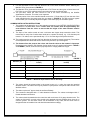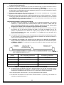
1
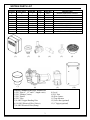
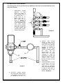
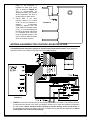
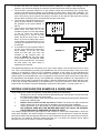
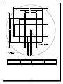
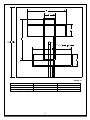
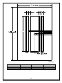
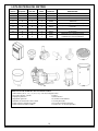
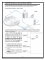
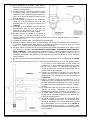
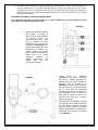
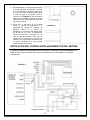
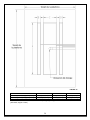
WetDek
INSTALLATION INSTRUCTIONS
AND OWNER’S MANUAL
CORPORATE HEADQUARTERS
WESTERN SALES AND MANUFACTURING PLANT
P.O. Box 400 ● 1017 SW Berg Parkway
Canby, Oregon 97013
(503) 266-2231 ● Fax (503) 266-4334
www.srsmith.com
06-901
© S.R. Smith LLC 2008
JUN14
INTRODUCTION
The WetDek is designed for use as a residential splash pad. Proper installation, use, and maintenance
are essential for optimal performance and to reduce the risk of accident or injury. These instructions are
developed and intended for use with either the stand alone or poolside versions of the WetDek with 6, 9,
or 12 nozzles.
**IMPORTANT**
Check entire box and inside all packing materials for parts. Before beginning assembly, read the
instructions and identify parts using the figures and parts listed in this document. It is critical that all
parts be carefully inspected by the installer prior to installation to ensure that no damage occurred in
transit and that a damaged part is not used. Proper installation cannot be overstressed, as improper
installation voids S.R. Smith’s warranty and may affect the safety of the user.
WARNINGS
This unit must be hardwired only to a supply circuit that is protected by a ground
fault circuit interrupter (GFCI). Such a GFCI is required by most building codes and should be
provided by the installer, and must be tested before each use. Consult GFCI manufacturers’ instructions
for correct testing and operation. A bonding lug has been provided on the outside of the electrical control
box. The lug permits the connection of No. 8 AWG solid copper bonding conductor between the controller
and all other electrical equipment and exposed metal in the vicinity. ALL ELECTRICAL CONNECTIONS
MUST COMPLY WITH NATIONAL ELECTRIC CODE, AS WELL AS ANY APPLICABLE LOCAL
CODES. A LICENSED ELECTRICIAN MUST BE USED FOR ALL ELECTRICAL CONNECTIONS.
The custom circuit board in the WetDek AquaDirector Controller has been tested before leaving
the manufacturing plant. A BLOWN CIRCUIT BOARD IS NOT COVERED UNDER THE WARRANTY
OF THIS PRODUCT. It is important to have a licensed electrician install the AquaDirector. Also, it is
important that they read the instructions provided here and the wire diagram in the controller to insure that
the circuit board is not damaged.
DANGER – RISK OF ELECTRICAL SHOCK. Install at least 5 feet (1.5m) away from all metal
surfaces. A WetDek may be installed within 5 feet of metal surfaces if each metal surface is permanently
connected by a minimum No. 8 AWG solid copper conductor that is bonded to the control box. Do not
permit any electrical appliance such as a light, telephone, radio, or television within 5 feet (1.5m)
of a WetDek.
EXTREME CAUTION – adult supervision required during use. Do not leave
children unattended around the WetDek. To avoid accidents and injury, insure that children
cannot use the Wetdek unless they are supervised by a responsible adult at all times. Do not use the
WetDek if the drain cover or nozzles are broken or malfunctioning in any way. A broken drain cover can
cause severe injury so examination of drain before each use is critical. Insure before use that drain cover
is secured and that drain is functioning properly. Note: the WetDek is not intended to be a wading pool of
any sort; do not allow use if pooling or back up of water occurs.
CHEMICAL SAFETY – Play it safe with chemicals. Maintain sanitizer level of 3-5 ppm of
bromine or chlorine. There is risk of illness if the water is not properly sanitized. Follow all chemical
manufacturers’ recommendations to insure proper sanitation. Always store chemicals according to the
manufacturer’s label directions and keep them out of reach of children. The stand alone model reservoir
should be emptied at least every two months.
2
WETDEK PARTS LIST
Poolside
X
X
X
X
X
X
X
Stand Alone
X
X
X
X
X
X
X
X
X
X
(1)
ITEM NO.
1
2
3
4
5
6
7
8
9
10
(2)
(7)
QTY.
1
6, 9, 12
4
4
1
1
1
1
1
1
PART NO.
30011
31000
30005
30006
30007
30013
30014
30001
30015
30004
(3)
DESCRIPTION
WetDek AquaDirector Controller
Brass Nozzles
1” HPV Valves
1” Valve Manifold Tee
1” Globe Valve
8” Drain w/ 6” ABS Hub
6” ABS to 4” PVC Converter
¾ HP Pump
25sf Filter Housing/Chlorinator
150 Gallon Reservoir w/ Fittings
(4)
(5)
(9)
(8)
ITEMS NEEDED FOR INSTALLATION
1) PVC Pipe (4”, 1.5” and 1”, length varies)
2) PVC Fittings (Varies)
3) PVC Primer
4) PVC Glue
5) 8 AWG Copper Bonding Wire
6) 16 AWG Electrical Wire (Valves)
7) 8 AWG Electrical Wire (Pump)
3
8) Level
9) PVC Saw
10) Wire Cutters
11) Tape Measure
12) Valve Box (optional)
13) 1” Spigot (optional)
(6)
(10)
WETDEK INSTALLATION GUIDELINES
The WetDek can be installed as a stand alone product or as a poolside feature. Each model requires
variations in installation. There is also a section of common installation requirements and a section for
optional additions that can be added to the system.
BACKYARD STAND ALONE MODEL
FIGURE 1
The stand alone version of the WetDek, shown in FIGURE 1, requires the installation of a dependent
pump and filtration system, as well as the placement of a 150 gallon reservoir. This is in addition to the
valve manifold, control box, and spray pad area that are required for all WetDeks.
Because the WetDek is based upon a
gravity drain, the top of the reservoir must be
located at least 6 inches lower than the drain.
This means that the reservoir should either be
positioned below ground level or placed downhill
from the WetDek surface (if the tank is located
underground, DO NOT BACKFILL AROUND
OR ON TOP OF THE TANK WITHOUT
PROPER REINFORCEMENT OR TANK MAY
COLLAPSE). The maximum change in height
from the WetDek surface to the standing
FIGURE 2
level of water in the reservoir is 5 feet; if more
height is required contact S.R. Smith. DO NOT
HOOK THE WETDEK UP TO A SUCTION
RETURN.
1. The 150 Gallon Reservoir (10) has four
fittings that are pre-attached to the tank.
There are three 1 ½” female threaded
fittings and one 4” female threaded fitting.
The dimensions for the tank are as follows:
32” diameter, 51” height.
2. The 4” fitting is designated for the drain line.
3. The three 1 ½” fittings are in-line with each
other, and are located 90 degrees from the
4” drain line, as shown in FIGURE 2.
4
4. The lowest fitting is designated for the
suction line to the pump.
5. The middle fitting is designated for the
recirculation/bypass line returning from the
valve manifold.
6. The top fitting on the reservoir should be
FIGURE 3
connected as an overflow pipe or as an auto-fill.
If used as an overflow pipe, it should run to a
French drain or other overflow area.
7. The ¾ HP Pump (8) and 25sf Filter/Chlorinator
(9) should be setup as shown in FIGURE 3.
8. The ¾ HP Pump (8) and 25sf Filter/Chlorinator
(9) require 1 ½” PVC pipe for both inlet and
outlet.
9. The inlet of the pump should be connected to
the lowest 1 ½” fitting on the reservoir; the
maximum height for the self-priming pump
above the waterline in the reservoir is 7 ft.
10. The pump outlet should run directly to the
filter/chlorinator.
11. From the filter/chlorinator to the valve manifold
the pipe should stay at 1 ½” as long as possible
to reduce pressure loss in the pipe, but it needs
to be scaled down to 1” before the valve
manifold.
12. The pump for the stand alone version of the WetDek should be wired directly to the control box that
comes with the WetDek. THIS CONNECTION MUST BE DONE BY A LICENSED ELECTRICIAN.
This will regulate when the pump runs in unison with the valves. The pump and controller run off of a
115 Volt power source. The WetDek AquaDirector Controller (1) is rated as a NEMA 3R enclosure,
which allows it to be placed indoors or outdoors.
13. The valve manifold for the Stand Alone version
should be setup as shown in FIGURE 4.
14. Each of the 1” Manifold Tees (4) should be
attached to one of the 1” HPV Valves (3). This is
done by threading the male portion of the
FIGURE 4
manifold tee to the female inlet side of the valve.
It is important to insure that the valve is placed
in the correct direction for the system to work
properly.
15. It is also important to insure that the valves are
all in the same orientation before attaching the
Manifold Tees (4) as shown in FIGURE 4.
16. The Manifold Tees (4) should first be wiped with
a PVC Primer and then given a liberal amount of
PVC Glue on one of the surfaces before
connecting the male and female ends.
17. The first three valves will each connect to one of
the zones controlled by the WetDek
AquaDirector Controller. The order is not
important.
18. The fourth valve will control the daily
recirculation function that is vital for the Stand
Alone version of the WetDek to insure that the
water remains clean.
19. The last portion of the valve manifold should
connect the 1” Globe Valve (5) from the end of
the valve manifold to the same line as the
recirculation line, as shown in FIGURE 4. This
will work as a bypass and will allow you to
manually adjust the heights of the water spray
for the whole system.
5
POOLSIDE MODEL
FIGURE 5
1. The proper layout for the WetDek poolside plumbing is located in FIGURE 5.
2. The poolside version of the WetDek should run off of an independent pump from the rest of the
pool. This independent pool pump will need to provide the following gallons per minute (GPM): a
six nozzle model will require 18 GPM minimum, a nine nozzle model will require 27 GPM
minimum, and a twelve nozzle model will require 36 GPM minimum. This pump should be
powered through the WetDek AquaDirector Controller (1) in the same manner as the Stand Alone
version.
3. Alternately, if the pool equipment is controlled by an intelligent system (i.e. Easy Touch,
AquaLink) then the pool pump can be setup to provide the water flow required. This will be
covered in the WetDek AquaDirector Controller Installation section.
4. The drain must be a minimum of 6” above the
surface of the water in the adjacent pool. This
will help to eliminate puddles from forming on
the surface. The drain should run directly to the
FIGURE 6
pool and MUST NEVER BE CONNECTED TO
A SUCTION RETURN. If bulkhead fittings are
used, the 4” drain line can be split into two 1 ½”
lines that run into the pool.
5. For existing pools, where bulkhead fittings would
be difficult, it is possible to hook up the drain line
to the pool return line as long as it is not
connected to the suction side.
6. The WetDek should have its own 1 ½” or 2” pipe
coming off of the independent pump. This
should be sized down to 1” pipe right before the
valve manifold.
7. The valve manifold for the Poolside version
should be setup as shown in FIGURE 6.
8. Each of the 1” Manifold Tees (4) should be
attached to one of the 1” HPV Valves (3). This is
done by threading the male portion of the
manifold tee to the female inlet side of the valve.
It is important to insure that the valve is placed
in the correct direction for the system to work
properly.
6
9. It is also important to insure that the valves are all in the same orientation before attaching the
Manifold Tees (4) as shown in FIGURE 6.
10. The Manifold Tees (4) should first be wiped with a PVC Primer and then given a liberal amount of
PVC Glue on one of the surfaces before connecting the male and female ends.
11. The first three valves will each connect to one of the zones controlled by the WetDek
AquaDirector Controller. The order is not important.
12. The last portion of the valve manifold should connect the 1” Globe Valve (5) from the end of the
valve manifold back to the pools return line, as shown in FIGURE 6. This will work as a bypass
and will allow you to manually adjust the heights of the water spray for the whole system.
COMMON INSTALLATION INSTRUCTIONS
1. The nozzles can be placed in any of the examples presented in the WETDEK CONFIGURATION
EXAMPLES & GUIDELINES section. Please note: all nozzles must be approximately the
same distance from the valves to assure that the height of the water streams remains
constant.
2. The slope of the surface needs to have a minimum two degree slope toward the drain. This
means that for every foot of radius there needs to be a quarter inch drop, e.g. 14 ft. diameter pad
means a 7 ft. radius, so the pad should drop 1 ¾ in. from the edge of the pad to the drain.
20. The nozzles must be at least two feet from the edge of the pad to prevent overspray. The nozzles
have adjustable ball valves that can be aimed in any direction, up to 60 degrees.
21. The distance from the pump to the valves and from the valves to the nozzles is important.
Depending on the distance, the diameter of pipe needs to vary for optimal performance. TABLE 1
and FIGURE 7, below, show the size of pipe required for varying distances of pipe.
FIGURE 7
Distance (Ft)
Pump to Valves (Pipe Diameter in
Inches)
Valves to Nozzles (Pipe Diameter in
Inches)
50
1.5
1
100
1.5
Not Recommended
150
2
Not Recommended
200
2
Not Recommended
250
Not Recommended
Not Recommended
TABLE 1 – Maximum Pipe Distance due to Viscosity
5. The valves should be placed either in the pump house or in a valve box near the intended
WetDek surface. The valves can only be placed in a pump house if the pad is within 50 feet of the
WetDek surface.
6. The drain requires a 4” pipe to drain the surface efficiently.
7. The nozzles are designed with a 1” male threaded connection. The valves are designed with 1”
female threaded connections.
8. The valves should be attached to the control box with a minimum of 16 gauge electrical wire. The
valves are 24 Volt AC, so each valve needs to be attached with two separate wires; there is no
common ground. The first three valves can be attached in any order, but the fourth valve is
designed as the recirculation line and should be attached accordingly.
7
OPTIONAL INSTALLATION ADD-ONS
The following items are not provided with your WetDek kit but can be purchased additionally from
many local suppliers.
1. ADDITIONAL GLOBE
VALVES:
To
help
control the height of
each individual zone it
is required that a 1”
Globe Valve (5) be
placed after each 1”
HPV Valve (3) as
shown in FIGURE 8.
This allows the WetDek
to be customized even
more. Water heights
can be set to the exact
same level or setup on
a tiered system that
separates each zone by
measured increments.
FIGURE 8
2. SPIGOT
FOR
STAND
ALONE: A spigot can be
incorporated in the stand
alone version of the WetDek
to allow for draining the
reservoir, as shown in
FIGURE 9; this spigot
should be located between
the
pump
(8)
and
filter/chlorinator (9). The
spigot must be easily
accessible to allow for
connection to a hose. No
spigot is required for the
poolside version because
the pool will have its own
drain system.
3. UNION FITTINGS: It is also
a good idea to use union
fittings before and after
each piece of equipment
used in the WetDek system
to allow for easy repair or
replacement. This is also
shown in FIGURE 9.
FIGURE 9
4. AUTO-FILL: Another optional
item for the Stand Alone version
of the WetDek, an Auto-Fill can
be attached to the top 1 ½”
8
fitting on the Reservoir to
regulate the water level in the
tank, as shown in FIGURE 10.
This is recommended for
WetDeks located in hot climates
where evaporation will have a
greater effect on water levels.
5. VALVE BOX: If the valve
manifold needs to be moved
closer to the pad because of
distance
requirements
(maximum distance from the
valve manifold to furthest nozzle
is 50’), it is recommended that
the valves be buried and placed
in a standard green valve box
used for sprinkler systems. This
can be used for either the Stand
Alone or Poolside versions.
FIGURE 10
WETDEK AQUADIRECTOR CONTROLLER INSTALLATION
The WetDek System Controller requires an onsite licensed electrician to install. These guidelines
should be used to insure that the controller has been installed properly.
FIGURE 11
1. FIGURE 11 shows the internal wiring for the WetDek AquaDirector Controller. The WetDek controller
is manufactured to handle 120V input; this diagram shows how to install the standard configuration
for 120V power. Please read this section carefully to prevent damage to the circuit board. All
circuit boards are tested twice before they leave our shop to insure that they are operational. A blown
circuit board is not covered under warranty.
9
2. All wires that enter the controller should be placed in NEMA-3R, or higher, rated fittings. For UL
purposes, the electrician installing the controller must drill these holes onsite and place the fittings.
3. The first wires connected should run to the solenoid valves and recirculation lines. These wires
connect to the Printed Circuit Board, and are labeled as follows: SOL1, SOL2, SOL3, RECIRC. The
valves are 24V AC, which means that each valve needs two wires to run directly from the board to the
valve. There will not be a common wire used for the valves. If the solenoid valve wires are touching
this will cause continuance in the circuit and will blow the circuit board.
4. The next item connected should be the
pump, and this should be connected to
the contactor in the inputs labeled T1
and T3.
5. The last wires connected should be the
power wires, and these run to the
contactor as well but on the side labeled
L1 and L2. (There are already black
wires running to L1 and L2, but the
power should be wired next to these
wires.) If you use a 240V power source
on the system as manufactured you will
overload the transformer and blow the
circuit board.
6. It is possible to run the system at 240V if
you are using a pump that requires this
FIGURE 12
much voltage. To do this you must
switch the wire that runs from the
contactor to the terminal block, as
shown in FIGURE 12. This wire needs
to be moved to the terminal that reads
240V on the terminal block. This should
be done before any other wiring is
attached to the controller.
The WetDek AquaDirector can be hooked up to a pool control system, such as the Easy Touch or Aqua
Link. This is accomplished by powering the AquaDirector from one of the free relays on the pool control
system. It is important to follow all of the installation guidelines in this section to avoid damaging the
AquaDirector. If attached to a pool control system, it is possible to run the pump through the pool control
system instead of the AquaDirector, but it is important to insure that the pump cannot be running when
the AquaDirector has stopped running. The AquaDirector is designed to default to an ON position for 30
minutes every time power is returned to the system. It will also remember the last program that was used.
If the pump is setup independently of the AquaDirector, it should be placed on a timer that shuts the
pump off after 30 minutes to prevent damaging a component of the system (i.e. pump, valves, etc…).
WETDEK CONFIGURATION EXAMPLES & GUIDELINES
When building your WetDek configuration, follow these guidelines for best results.
1.
All piping from valve to nozzle should be approximately the same length. This will insure that
the water shoots equally from each nozzle.
2.
To avoid forming puddles, make sure that the drain is located at the lowest point and that the
surface has a steady slope.
3.
Nozzles must be placed so that top surface is level. The surface can slope around the
nozzle, and the ball on the nozzle can be adjusted to aim the water after installation.
4.
Surface options are up to the installer; we recommend using stamped or brushed concrete.
ANY SURFACE USED WITH THE WETDEK MUST MEET ANY LOCAL OR NATIONAL
CODES FOR NON-SLIP SURFACES AND HEALTH SAFETY.
The following images show the pipe layouts for the nozzles for various pad configurations. These are
some stock examples, but custom designs are encouraged to give each project a unique feel. Nozzles
should be divided evenly amongst the three zones (Two nozzles per zone for a 6 nozzle kit, three nozzles
per zone for a 9 nozzle kit, and four nozzles per zone for a 12 nozzle kit). Nozzles can be placed
anywhere on the loop to allow for maximum customization.
10
FIGURE 13
PAD SIZE
A*
11’ Diameter (6 Nozzles)
84
13’ Diameter (9 Nozzles)
108
15’ Diameter (12 Nozzles)
132
TABLE 2 *All dimensions given in inches
B*
48
72
96
11
C*
24
36
48
FIGURE 14
PAD SIZE
12’ x 12’ (6 Nozzles)
14’ x 14’ (9 Nozzles)
16’ x 16’ (12 Nozzles)
TABLE 3 *All dimensions given in inches
A*
24
36
48
12
B*
84
108
132
FIGURE 15
PAD SIZE
A*
12’ x 8’ (6 Nozzles)
96
14’ x 10’ (9 Nozzles)
120
16’ x 12’ (12 Nozzles)
144
TABLE 4 *All dimensions given in inches
B*
6
12
18
13
C*
24
36
48
OPERATING THE CONTROLLER
The control box that operates the WetDek has three buttons, which are used to control the system, and
four lights, as well as a four digit numerical display. The three buttons are labeled “Sel”, “Inc/+”, and
“Dec/-“. The four lights are labeled “Program Select”, “Run Time”, “Recirc Start”, and “Time of Day”.
Buttons
Sel
This button allows you to change between the different light functions.
Inc/+
This button will increase the variable on the numerical display by one. To
increase time quickly, press and hold the button down
Dec/-
This button will decrease the variable on the numerical display by one. To
decrease time quickly, press and hold the button down
Lights
Program Select
There are five programs to choose in the “Program Select” light, numbered 1-5:
program 1 is a set pattern of one zone at a time with variable timeframes,
program 2 is a set pattern of two or three zones for variable timeframes, program
3 is a randomized spray of variable time, program 4 is all of the jets spraying
continuously, and program 5 cycles through all four of the other programs.
Run Time
The run time can be set from 1 minute to 23 hours and 59 minutes. The system
will shut itself off after the time frame has elapsed.
Recirc Start
The start time for the recirculation function of the control box. It is meant to
control the fourth solenoid valve and determines what time of day that it should
run at. Generally, you would pick a time when the system would not normally be
running because it will take away from the overall performance of the WetDek.
Recirculation is only required on Stand Alone versions of the WetDek.
Time of Day
Time of Day is set as a reference for the recirculation line and should remain
constant, even if the box is unplugged because a battery is present to run the
clock.
COMMONLY ASKED QUESTIONS
1. How do you hook up the controller to Pentair, Jandy and Hayward controllers? Just one power
cord going from the SRS box to the controller. It will only use one relay on the automation system and
will only control turning the box on/off.
2. What size pump is required for the pool kit version? The builder should know the capabilities of
the preexisting equipment. The size of the pump and filter will always be determined by the hydraulics
and the body of water. Things like how far away the equipment is, to plumbing size or number of
fittings, can determine this.
3. How thick should the concrete slab be? Should rebar be used? The concrete slab should be 4”
thick, and does not require rebar (although some local codes might require that rebar be used). The
nozzles need to be grounded so this will help; otherwise, copper wire must be connected from each
of the nozzles to a grounding point.
4. What should the slab size be for either a square or round pad for each unit? What about
different shape slab; will SRS help with jet and drain placement? For a 6 nozzle WetDek the
recommended minimum size is either an 11’ diameter circle or a 12’ x 12’ square. This is to minimize
the amount of water lost. Obviously someone could put it in a smaller pad, but an auto-fill would
become a necessity and other issues could come up, so we do not recommend using a smaller pad.
SR Smith can help design custom pads but the customer will be charged for this service.
5. How to keep water from entering the drain in the winter? The easiest way to do this would be to
keep the cover (which is plastic) or use a similar material and place it under the grate and tighten it in
place.
6. Can the nozzles be placed in the deck of a new pool and shoot water into the pool? Yes, there
are endless possibilities for location of the nozzles and this one simplifies the process because of the
removal of a drainage system.
7. How long does it take to complete the whole job on a stand alone with 6 nozzles? Generally 3
days but after completing a few units this should be reduced to 1.5 to 2 days.
14
WETDEK CARE & MAINTENANCE
There are a couple of areas of the WetDek that require regular maintenance: water, plumbing, and the
pump. Routine checks will help prolong the life of all components of the WetDek.
WATER TESTING
It is recommended that you test your WetDek water regularly with an accurate test kit or test strips. These
are available from your local Pool & Spa Dealer. Also, be sure to follow chemical manufacturers’
instructions for chemical use.
pH CONTROL
All water solutions have pH, which is a measure of the acid to base relationship. A pH reading of 7.0 is
neutral, a lower reading is acidic and a higher reading is basic. The proper pH for WetDek water is
between 7.4 and 7.6 High pH (above 7.6) can reduce sanitizer efficiency, cloud the water, promote scale
formation on surfaces and equipment, and interfere with filter operations. When pH is too high, add a pH
decreaser. Low pH (below 7.2) is equally damaging and can cause equipment corrosion, water that is
irritating, and rapid sanitizer dissipation. Add pH increaser to bring the pH higher.
It is important to use scale and stain inhibitor weekly to prevent calcium deposits from damaging your
WetDek and equipment. If this happens, it could void the warranty. Refer to your chemical handbook for
further information on water chemistry and troubleshooting.
DRAINING THE WATER
Locate the spigot between the chlorinator and valve manifold. Attach a garden hose and open the valve.
The controller should be set to recirculation during draining. Any water that the pump does not remove
should be sucked out with a wet/dry vacuum.
FILTER MAINTENENCE
At least once a month, (or more often based on environmental conditions) check and clean the skimmer
basket of the pump to ensure proper flow. Remove leaves, foreign matter and debris when present. It is
also very important to maintain your WetDek filter cartridge clean and free of particles that can obstruct
water flow. A clean filter will permit the system to function properly and also allows more efficient filtering.
Depending on how frequently your WetDek is used, we recommend cleaning the WetDek filter cartridge
every four to six weeks. If this is not done, the filter may clog and restrict water flow, which causes
inadequate filtration and poor nozzle performance.
CLEANING THE FILTER
Carefully pull up the filter cartridge and bring it out of the WetDek. Rinse cartridge using a garden hose.
Rotate and separate filter pleats while spraying water to remove all debris possible. Let the filter dry and
look for calcium deposits (scaling) or an oil film. If you find these, you will need to deep clean your filter
cartridge with a “spa filter cleaning” solution to break down and remove mineral deposits and oils.
WINTERIZATION
You must winterize the WetDek when freezing temperatures are expected or if prolonged periods without
use are expected; this will help protect all components. Water should be drained from the reservoir in the
stand alone model, and water should be cleared from the pump, filter, chlorinator, and all piping. The balls
in the nozzles should be rotated so that no water can drain into them, and then tightened.
IMPORTANT
PERSONALLY GIVE TO OWNER THIS WETDEK OWNER’S MANUAL, THE
WARRANTY CARD AND ANSWER ALL QUESTIONS.
15
WetDek
INSTRUCCIONES PARA LA INSTALACIÓN
Y MANUAL DEL PROPIETARIO
OFICINAS GENERALES
PLANTA OCCIDENTAL DE VENTAS Y FABRICACIÓN
P.O. Box 400 ● 1017 SW Berg Parkway
Canby, Oregon 97013
(503) 266-2231 ● Fax (503) 266-4334
www.srsmith.com
16
INTRODUCCIÓN
El WetDek ha sido construido para utilizarse como una atracción acuática residencial para chapotear. Su
instalación, utilización y mantenimiento correctos son esenciales para que funcione óptimamente y
disminuya el riesgo de un accidente o una lesión. Se redactaron estas instrucciones para utilizarse ya
sea con la plataforma sola o con las versiones del WetDek con 6, 9, ó 12 boquillas para instalarse al lado
de la alberca.
**IMPORTANTE**
Revise toda la caja y el interior de los materiales del empaque para encontrar las piezas. Antes de
comenzar con el ensamblado, lea las instrucciones e identifique las piezas consultando las figuras y
las piezas enumeradas en este documento. Es esencial que el instalador inspeccione todas las piezas
detenidamente antes de la instalación para asegurar que no se hayan dañado en tránsito y que no se
utilice una pieza dañada. Hacemos mucho hincapié en la instalación correcta, ya que una instalación
indebida anula la garantía de S.R. Smith y podría afectar la seguridad del usuario.
ADVERTENCIAS
Se debe conectar esta unidad únicamente a un circuito de suministro protegido con un
interruptor de circuito sin conexión a tierra (GFCI, por sus siglas en inglés). La mayoría de
los códigos de construcción requieren tal GFCI, el cual debe ser provisto por el instalador y probado
antes de cada uso. Consulte las instrucciones de los fabricantes de los GFCI para probarlos y operarlos
correctamente. Se ha incluido una aleta de conexión en el exterior de la caja eléctrica de control. La aleta
permite conectar el conductor de conexión de cobre sólido No. 8 AWG entre el controlador y todo el otro
equipo eléctrico y metal expuesto en los alrededores. TODAS LAS CONEXIONES ELÉCTRICAS
DEBEN CUMPLIR CON EL CÓDIGO ELÉCTRICO NACIONAL Y CON TODOS LOS CÓDIGOS
LOCALES PERTINENTES. DEBE CONTRATARSE A UN ELECTRICISTA PROFESIONAL
AUTORIZADO PARA QUE REALICE TODAS LAS CONEXIONES ELÉCTRICAS.
Se ha probado el tablero del circuito hecho a la medida del Controlador AquaDirector del WetDek
antes de salir de la planta manufacturera. LA GARANTÍA DE ESTE PRODUCTO NO CUBRE UN
TABLERO DEL CIRCUITO QUEMADO. Es importante que un electricista profesional autorizado instale
el AquaDirector y que se lean las instrucciones proporcionadas aquí y el diagrama de los cables en el
controlador para asegurarse de que el tablero del circuito no haya sido dañado.
PELIGRO – RIESGO DE CHOQUE ELÉCTRICO. Instale la unidad por lo menos a 5 pies (1.5
m) de distancia de toda superficie metálica. Un WetDek puede instalarse a 5 pies o menos de superficies
metálicas si cada una de ellas está conectada permanentemente por un conductor de cobre sólido (No. 8
AWG como mínimo) que va conectado a la caja de control. No permita que haya ningún aparato
eléctrico como lámpara, teléfono, radio o televisión a 5 pies (1.5 m) o menos de un WetDek.
PRECAUCIÓN EXTREMA – la supervisión adulta es obligatoria durante el uso. No
deje a los niños alrededor del WetDek sin atenderlos. Para evitar accidentes y lesiones,
cerciórese de que los niños no puedan utilizar el WetDek a menos que estén siendo supervisados por
un adulto responsable en todo momento. No use el WetDek si la cubierta del drenaje o las boquillas
se han roto o funcionan mal de la manera que sea. Una cubierta rota del drenaje puede causar lesiones
graves por lo que es esencial revisarla antes de cada uso. Antes el uso, asegúrese que la cubierta del
drenaje esté fija y que el drenaje funcione debidamente. Nota: el WetDek no se construyó para ser
ningún tipo de alberca para niños; no permita su uso si se forma un estanque o si se acumula el agua.
SEGURIDAD QUÍMICA – cuídese de las sustancias químicas. Mantenga la
concentración del desinfectante de 3 a 5 ppm de bromo o cloro. Hay riesgo de enfermedad si el agua
no ha sido debidamente desinfectada. Siga todas las recomendaciones de los fabricantes químicos
para asegurar la desinfección adecuada. Siempre almacene las sustancias químicas conforme a las
indicaciones de la etiqueta del fabricante y déjelas fuera del alcance de los niños. Se debe vaciar el
depósito del modelo separado por lo menos cada dos meses.
17
LISTA DE PIEZAS DEL WETDEK
Junto a la
alberca
Separado
NO. ART.
CANT.
PIEZA NO.
DESCRIPCIÓN
X
X
1
1
30011
Controlador AquaDirector del WetDek
X
X
2
6, 9, 12
31000
Boquillas de latón
X
X
3
4
30005
X
X
4
4
30006
Válvulas HPV de 1” (2.54 cm)
Accesorio en T de 1” (2.54 cm) de la válvula de
distribución
X
X
5
1
30007
X
X
6
1
30013
X
X
7
1
30014
X
8
1
30001
X
X
9
10
1
1
30002
30004
(1)
(7)
(2)
(3)
Válvula de globo de 1” (2.54 cm)
Drenaje de 8” (20.3 cm) con cubo ABS de 6”
(14.2 cm)
Convertidor del ABS de 6” (15.2 cm) a PVC de
4” (10.2 cm)
Bomba de ¾ de caballos de fuerza
Cubierta del filtro/Clorinador para 25 pies
cuadrados (2.3 metros cuadrados)
Depósito de 150 galones (567.8 l) con accesorios
(4)
(8)
(5)
(9)
ARTÍCULOS NECESARIOS PARA LA INSTALACIÓN
1) Tubo de PVC (de 4”, 1.5” y 1” (10.1, 3.8 y 2.54 cm) la longitud varía)
2) Accesorios de PVC (varían)
8) Nivel
3) Tapaporos para PVC
9) Sierra de PVC
4) Pegamento para PVC
10) Tenazas corta alambres
5) Alambre de conexión de cobre 8 AWG
11) Cinta para medir
6) Cable eléctrico (válvulas) 16 AWG
12) Caja de la válvula (opcional)
7) Cable eléctrico (bomba) 8 AWG
13) Llave de 1” (2.54 cm) (opcional)
18
(6)
(10)
DIRECTRICES PARA LA INSTALACIÓN DEL WETDEK
Se puede instalar el WetDek como producto separado o junto a la alberca. Cada modelo tiene una
manera de instalación un poco distinta. También hay una sección de requerimientos comunes de
instalación y otra sección para adiciones opcionales que pueden añadirse al sistema.
MODELO SEPARADO PARA EL JARDÍN TRASERO
FIGURA 1
La versión separada del WetDek que se muestra en la FIGURA 1 requiere la instalación de un sistema
dependiente de bombeo y filtración así como la colocación de un depósito de 150 galones (567.8 l)
además de la válvula de distribución, la caja de control y el área para la plataforma para salpicar que
requieren todos los WetDeks.
Ya que el WetDek funciona con drenaje por
gravedad, se debe colocar la parte superior del
depósito por lo menos 6 pulgadas (15.2 cm)
más abajo que el drenaje. Esto significa que se
debe enterrar o colocar el depósito más abajo que
la superficie del WetDek. La máxima
modificación de altura desde la superficie del
WetDek hasta el nivel estacionario del agua en
el depósito es 5 pies (1.5 m); si necesita más
altura, diríjase a S.R. Smith. NO CONECTE EL
FIGURA 2
WETDEK A UNA SUCCIÓN DE RETORNO.
22. El depósito de 150 galones (10) tiene cuatro
accesorios previamente unidos al tanque. Hay
tres accesorios hembra roscados de 1 ½” (3.8
cm) y uno de 4” (10.1 cm). El tanque mide 32”
(81.3 cm) de diámetro y 51” (129.5 cm) de altura.
23. El accesorio de 4” (10.1 cm) es para la tubería
del drenaje.
24. Los tres accesorios de 1 ½” están alineados
mutuamente y ubicados a 90 grados de la
tubería del drenaje de 4”, como se aprecia en
la FIGURA 2.
25. Se ha designado el accesorio más bajo como
tubería de succión a la bomba.
19
26. Se ha designado el accesorio central para la
FIGURA 3
tubería de recirculación/desvío que regresa de
la válvula de distribución.
27. Se debe conectar el accessorio superior sobre
el depósito como tubo de derrame o llenado
automático. Si se utiliza como tubo de derrame,
debe ir a un drenaje de piedra en zanja o a otra
área de derrame.
28. Se debe instalar la bomba de ¾ de caballos de
fuerza (8) y el filtro/clorinador para 25 pies
2
cuadrados (2.3 m ) (9) como se muestra en la
FIGURA 3.
29. La bomba de ¾ de caballos de fuerza (8) y el
filtro/clorinador para 25 pies cuadrados (9)
requieren un tubo de PVC de 1 ½” (3.8 cm)
tanto para la entrada como para la salida.
30. Se debe conectar la entrada de la bomba al
accesorio de 1 ½” que está más abajo en el
depósito; la altura máxima para la bomba autocebante por encima del nivel del agua en el depósito
es de 7 pies (2.1 m).
31. La salida de la bomba debe ir directamente al filtro/clorinador.
32. Se debe mantener la tubería desde el filtro/clorinador a la válvula de distribución en un tamaño de 1
½” la mayor longitud posible para disminuir la pérdida de presión en la tubería, pero se necesita
reducir a 1” (2.54 cm) antes de llegar a la válvula de distribución.
33. Se debe cablear la bomba para la versión separada del WetDek directamente a la caja de control
que viene con el WetDek. UN ELECTRICISTA PROFESIONAL AUTORIZADO DEBE REALIZAR
ESTA CONEXIÓN. Tendrá una función reguladora cuando la bomba trabaje al unísono con las
válvulas. La bomba y el controlador funcionan con una fuente de poder de 115 voltios. Ya que el
controlador AquaDirector del WetDek (1) está aprobado para cobertura NEMA 3R, puede colocarse
afuera o adentro.
34. Se debe instalar la válvula de distribución para la versión separada como se muestra en la FIGURA
4.
35. Se debe fijar cada accesorio en T de 1” (2.54 cm) de la distribución (4) a una de las válvulas HPV de
1” (3). Esto se hace enroscando la parte macho del
accesorio en T de la distribución al lado de la entrada
hembra de la válvula. Es importante asegurarse de
colocar la válvula en la dirección correcta para que el
sistema funcione debidamente.
36. También es importante cerciorarse de que todas las
FIGURA 4
válvulas tengan la misma orientación antes de fijar los
accesorios en T de la distribución (4) como se muestra en
la FIGURA 4.
37. Primero, se deben limpiar los accesorios en T de la
distribución (4) con un tapaporos para PVC y luego poner
una capa abundante de pegamento para PVC en una de
las superficies antes de conectar los extremos macho y
hembra.
38. Se conectarán cada una de las primeras tres válvulas a
una de las zonas controladas por el controlador
AquaDirector del WetDek. El orden no es importante.
39. La cuarta válvula controlará la recirculación diaria vital
para la versión separada del WetDek para asegurar que
el agua se mantenga limpia.
40. La última sección de la válvula de distribución debe
conectar la válvula de globo de 1” (5) del extremo de la
válvula de distribución a la misma tubería como aquélla
de la recirculación, como se muestra en la FIGURA 4.
Esto funcionará como un desvío y le permitirá ajustar
manualmente las distintas alturas del rocío de agua para
todo el sistema.
20
MODELO AL LADO DE LA ALBERCA
FIGURA 5
13. La FIGURA 5 muestra el trazado correcto para la plomería del WetDek al lado de la alberca.
14. La versión del WetDek al lado de la alberca debe funcionar con una bomba independiente del resto
de la alberca que deberá suministrar los siguientes galones por minuto (GPM): el modelo con 6
boquillas requerirá un mínimo de 18 GPM (68.1 l), el de 9 boquillas requerirá un mínimo de 27 GPM
(102.2 lpm) y el de 12 boquillas un mínimo de 36 GPM (136.3 lpm). El controlador AquaDirector del
WetDek (1) debe activar esta bomba de la misma manera que funciona el modelo separado.
15. En cambio, si un equipo inteligente (Easy Touch o AquaLink, por ejemplo) controla el equipo de la
alberca, entonces se puede instalar la bomba de la alberca para suministrar la corriente de agua
necesaria. La sección “Instalación del controlador AquaDirector del WetDek” tratará esto.
16. El drenaje deberá estar por lo menos a 6” (15.2 cm)
por encima de la superficie del agua en la alberca
contigua para ayudar a que no se formen charcos en
la superficie. El drenaje debe ir directamente a la
FIGURA 6
alberca y NUNCA DEBE CONECTARSE A UN
RETORNO DE SUCCIÓN. Si se usan accesorios de
tapón, se puede dividir la tubería del drenaje de 4”
(10.2 cm) en dos tuberías de 1 ½” (3.8 cm) que van a
la alberca.
17. Para las albercas existentes, donde sería difícil
instalar accesorios de tapón, se puede conectar la
tubería del drenaje a la tubería de retorno de la
alberca siempre que no esté conectada al lado de
succión.
18. El WetDek debe tener su propia tubería de 1 ½” ó
2” (3.8 ó 5.1 cm) que sale de la bomba
independiente y se debe reducir esta tubería a una
tubería de 1” (2.54 cm) justo antes de la válvula de
distribución.
19. Se debe instalar la válvula de distribución para el
modelo al lado de la alberca como se muestra en
la FIGURA 6.
20. Se debe fijar cada accesorio en T de 1” de la
distribución (4) a una de las válvulas HPV de 1”
(3) enroscando la parte macho del accesorio en T
de la distribución al lado de la entrada hembra de
21
21.
22.
23.
24.
la válvula. Es importante asegurarse de que la válvula sea colocada en la dirección correcta para que
el sistema funcione debidamente.
También es importante cerciorarse de que todas las válvulas tengan la misma orientación antes de
fijar los accesorios en T de la distribución (4) como se muestra en la FIGURA 6.
Primero, se deben limpiar los accesorios en T de la distribución (4) con un tapaporos de PVC y luego
se debe aplicar una cantidad abundante de pegamento para PVC en una de las superficies antes de
conectar los extremos macho y hembra.
Cada una de las primeras tres válvulas irán a una de las zonas controladas por el controlador
AquaDirector del WetDek. El orden no es importante.
Se debe conectar la última sección de la válvula de distribución a la válvula de globo de 1” (5) desde
el final de la válvula de distribución de regreso a la tubería de retorno de la alberca, como se muestra
en la FIGURA 6. Esto funcionará como un desvío y le permitirá ajustar manualmente las distintas
alturas del rocío de agua para todo el sistema.
INSTRUCCIONES PARA LA INSTALACIÓN COMÚN
1. Se pueden colocar las boquillas en cualquiera de los ejemplos presentados en la sección
EJEMPLOS Y DIRECTRICES DE CONFIGURACIÓN PARA EL WETDEK. Tome nota que
todas las boquillas deberán estar a la misma distancia aproximada de las válvulas para
asegurar que la altura de las corrientes del agua permanezca constante.
2. La superficie necesita tener una inclinación mínima de dos grados hacia el drenaje, o sea que
por cada pie (30 cm) de radio se necesita una caída de un cuarto de pulgada (0.6 cm). Por
ejemplo, una plataforma con un diámetro de 14 pies (4.3 m) equivale a un radio de 7 pies (2.2
m), así que la plataforma debe tener una caída de 1 ¾ pulgadas (4.4 cm) del borde de la
plataforma hacia el drenaje.
41. Las boquillas deben estar por lo menos a dos pies (60 cm) del borde de la plataforma para evitar
un rocío excesivo. Las boquillas tienen válvulas esféricas ajustables que pueden apuntarse un
máximo de 60 grados hacia cualquier dirección.
42. La distancia de la bomba a las válvulas y de las válvulas a las boquillas es importante.
Según la distancia, el diámetro de la tubería necesita variar para tener un funcionamiento óptimo.
La TABLA 1 y FIGURA 7, a continuación, muestran el tamaño de tubería necesario para varias
distancias de tubería.
FIGURA 7
Distancia en pies
(metros)
Distancia bomba a válvulas (diámetro del
tubo en pulgadas y centímetros)
Válvulas a boquillas (diámetro del tubo
en pulgadas y centímetros)
50’ (15.2 m)
1.5” (3.8 cm)
1” (2.54 cm)
100’ (30.5 m)
1.5 “ (3.8 cm)
No se recomienda
150’ (45.7 m)
2” (5.1 cm)
No se recomienda
200’ (61 m)
2” (5.1 cm)
No se recomienda
250’ (76.2 m)
No se recomienda
No se recomienda
TABLA 1 – Distancia máxima de la tubería debido a la viscosidad
9. Se deben colocar las válvulas ya sea en la casa de bombas o en una caja de válvulas cerca de
la superficie destinada para el WetDek. Se pueden colocar las válvulas en la casa de bombas
solamente si la plataforma está a 50 pies (15.2 m) o menos de la superficie del WetDek.
10. El drenaje requiere una tubería de 4” (10.2 cm) para drenar bien la superficie.
11. Se fabricaron las boquillas con una conexión roscada macho de 1” (2.54 cm) y las válvulas con
conexiones roscadas hembra de 1”.
22
12. Se deben fijar las válvulas a la caja de control con cable eléctrico de calibre 16 como mínimo. Ya
que las válvulas son de 24 voltios corriente alterna, se debe fijar cada una con dos cables
separados; no hay una conexión a tierra común. Se pueden fijar las primeras tres válvulas en
cualquier orden, pero la cuarta válvula está diseñada como línea de recirculación y se la debe
fijar como corresponde.
SUPLEMENTOS PARA LA INSTALACIÓN OPCIONAL
Los siguientes artículos no forman parte de su equipo WetDek pero puede adquirirlos como
opciones de muchos distribuidores locales.
FIGURA 8
6. MÁS VÁLVULAS DE GLOBO:
para ayudar a controlar la
altura de cada zona individual
se necesita colocar una
válvula de globo de 1” (2.54
cm) (5) después de cada
válvula HPV de 1” (3) como se
muestra en la FIGURA 8. Esto
permite darle toques aún más
individuales al WetDek. Se
pueden ajustar las alturas
para el agua exactamente al
mismo nivel o se puede
configurar
utilizando
un
sistema
superpuesto
que
separa
cada
zona
por
incrementos medidos.
7. LLAVE
PARA
EL
MODELO
SEPARADO: Se puede incorporar
una llave al modelo separado del
WetDek para que pueda drenarse el
depósito, como se muestra en la
FIGURA 9; se debe colocar esta llave
entre la bomba (8) y el filtro/clorinador
(9). La llave debe ser fácilmente
accesible para permitir la conexión a
una manguera. No se necesita una
llave para el modelo al lado de la
alberca porque éste tiene su propio
sistema de drenaje.
FIGURA 9
8. ACCESORIOS DE UNIÓN: también
es una buena idea utilizar accesorios
de unión antes y después de cada
pieza de equipo usado en el sistema
WetDek para facilitar su reparación o
sustitución. Esto también se muestra
en la FIGURA 9.
23
9. AUTOLLENADO: otro artículo opcional para
la versión separada del WetDek, se puede
fijar el autollenado al accesorio superior de
1 ½” (3.8 cm) sobre el depósito para regular
el nivel del agua en el tanque, como se
muestra en la FIGURA 10. Se recomienda
esto para los WetDeks instalados en climas
cálidos donde la evaporación afectará más
los niveles del agua.
10. CAJA DE LA VÁLVULA: si se necesita
acercar la válvula de distribución a la
plataforma por razones de distancia (la
distancia máxima de la válvula de
distribución a la boquilla más alejada debe
ser de 50 pies o 15.2 m), recomendamos
enterrar las válvulas y colocarlas en una
caja de válvulas estándar verde que se
utiliza para los sistemas de extinción de
incendios. Se puede utilizar esto tanto para
la versión separada como para aquélla
ubicada al lado de la alberca.
FIGURA 10
INSTALACIÓN DEL CONTROLADOR AQUADIRECTOR DEL WETDEK
Un electricista profesional autorizado tiene que instalar el controlador del sistema WetDek en el
lugar. Se debe consultar estas directrices para cerciorarse de que se ha instalado el controlador
correctamente.
FIGURA 11
24
7. La FIGURA 11 muestra el cableado interno para el controlador AquaDirector del WetDek, fabricado
para funcionar con 120V; este diagrama muestra cómo instalar la configuración estándar para un
voltaje de 120V. Por favor lea esta sección detenidamente para evitar que se dañe la tarjeta de
circuitos. Probamos todas las tarjetas de circuitos dos veces antes de salir de nuestra fábrica para
asegurarnos de que funcionen totalmente. La garantía no cubre una tarjeta de circuitos
quemada.
8. Se deben usar todos los cables que entran al controlador en los accesorios con la clasificación
NEMA-3R o superior. Para los fines de los laboratorios UL, el electricista que instale el controlador
deberá taladrar estos orificios en el lugar y colocar los accesorios.
9. Los primeros cables conectados deben ir hacia las válvulas de solenoide y las líneas de
recirculación. Conecte estos cables a la tarjeta de circuito impreso y rotúlelos como sigue: SOL1,
SOL2, SOL3, RECIRC. Las válvulas son de corriente alterna de 24V, lo que significa que cada una
necesita dos cables que vayan directamente de la tarjeta a la válvula. No se usará un cable común
para las válvulas. Si se tocan los cables de la válvula de solenoide habrá continuidad en el circuito y
se quemará la tarjeta de circuitos.
10. El siguiente artículo que se debe conectar es la bomba, la cual se debe conectar al contactor en las
entradas rotuladas T1 y T3.
11. Los cables de energía eléctrica son los últimos
cables que deben conectarse y éstos van también
hacia el contactor, pero en el lado rotulado L1 y
L2. (Ya hay cables negros que van a L1 y L2, pero
se debe conectar la potencia debe conectarse al
lado de estos cables.) Si utiliza una fuente de
potencia de 240V en el sistema fabricado, se
sobrecargará el transformador y se quemará la
tarjeta de circuitos.
12. Es posible hacer funcionar al sistema con 240V si
está usando una bomba que requiera tanto voltaje.
Para hacerlo, debe cambiar el cable que va del
FIGURA 12
contactor al bloque de terminal, como se muestra
en FIGURA 12. Se necesita mover este cable a la
terminal que diga 240V en el bloque de terminal y
efectuar esto antes de conectar cualquier otro
cable al controlador.
Se puede conectar el AquaDirector del WetDek a un sistema controlador de albercas como el Easy
Touch o Aqua Link. Se hace esto activando el AquaDirector desde uno de los relevadores libres en el
sistema controlador de albercas. Es importante seguir todas las directrices de instalación en esta sección
para evitar daños al AquaDirector. Si se fija al sistema controlador de albercas, es posible activar la
bomba a través del sistema controlador de albercas en vez de a través del AquaDirector, pero es
importante asegurarse de que la bomba no pueda funcionar cuando el AquaDirector haya sido apagado.
El AquaDirector fue construido para que por predeterminación vuelva a la posición de encendido (ON)
durante 30 minutos cada vez que se vuelva a encender el sistema. También recordará el último
programa utilizado. Si se instaló la bomba independientemente del AquaDirector, debe ir conectada a un
reloj automático que apaga la bomba después de 30 minutos para evitar que se dañe un componente del
sistema (como la bomba, las válvulas, etc…).
EJEMPLOS Y DIRECTRICES PARA CONFIGURAR EL WETDEK
Cuando construya su configuración del WetDek, siga estas directrices para obtener los mejores
resultados:
5.
Cada tubo que vaya de la válvula a la boquilla debe tener la misma longitud aproximada para
asegurar que el agua salga disparada igualmente de cada boquilla.
6.
Para evitar la formación de charcos, fíjese que el drenaje esté ubicado en el punto más bajo
y que la superficie tenga una inclinación constante.
7.
Se deben colocar las boquillas de tal manera que la superficie superior esté nivelada.
La superficie puede inclinarse alrededor de la boquilla y se puede ajustar la bola de la
boquilla después de la instalación con el propósito de apuntar el agua.
8.
El instalador puede seleccionar la superficie que desee, recomendamos usar concreto
estampado o cepillado. TODA SUPERFICIE UTILIZADA PARA EL WETDEK DEBERÀ
25
CUMPLIR CON CUALQUIER CÓDIGO NACIONAL O LOCAL PARA SUPERFICIES
ANTIDERRAPANTES Y DE SEGURIDAD SANITARIA.
Las siguientes imágenes muestran los trazados de la tubería para las boquillas de varias configuraciones
de plataformas. Se muestran ejemplos del archivo, pero recomendamos diseños hechos por encargo
para darle un toque individual a cada proyecto. Se deben dividir las boquillas equitativamente entre las
tres zonas (dos boquillas por zona para un juego de 6 boquillas, tres boquillas por zona para un juego de
9 boquillas y cuatro boquillas por zona para un juego de 12 boquillas). Se pueden colocar las boquillas
en cualquier lugar de la curva para lograr máxima individualización.
FIGURA 13
TAMAÑO DE LA PLATAFORMA
A*
B*
C*
11’ (3.4 m) de diámetro (6 boquillas)
84” (213.3 cm)
48” (121.9 cm)
24” (61 cm)
13’ (4 m) de diámetro (9 boquillas)
108” (274.3 cm)
72” (182.9 cm)
36” (91.4 cm)
15‘ (4.6 m) de diámetro (12 boquillas)
132” (335.3 cm)
96” (243.8 cm)
48” (121.9 cm)
TABLA 2 *Todas las dimensiones se indican en pies y pulgadas (y en centímetros o metros entre
paréntesis, según el caso)
26
FIGURA 14
TAMAÑO DE LA PLATAFORMA
A*
B*
12’ x 12’ (3.7 x 3.7 m) (6 boquillas)
24” (61 cm)
84” (213.3 cm)
14’ x 14’ (4.3 x 4.3 m) (9 boquillas)
36” (91.4 cm)
108” (274.3 cm)
16’ x 16’ (4.9 x 4.9 m) (12 boquillas)
48” (121.9 cm)
132” (335.3 cm)
TABLA 3 * Todas las dimensiones se indican en pies y pulgadas (y en centímetros o metros entre
paréntesis, según el caso)
27
FIGURA 15
TAMAÑO DE LA PLATAFORMA
A*
B*
C*
12’ x 8’ (3.7 x 2.4 m) (6 boquillas)
96” (243.8 cm)
6” (15.2 cm)
24” (61 cm)
14’ x 10’ (4.3 x 2.5 m) (9 boquillas)
120” (304.8 cm)
12” (30.5 cm)
36” (91.4 cm)
16’ x 12’ (4.9 x 3.7 m) (12 boquillas)
144” (365.8 cm)
18” (45.7 cm)
48” (121.9 cm)
TABLA 4 * Todas las dimensiones se indican en pies y pulgadas (y en centímetros o metros entre
paréntesis, según el caso)
28
CÓMO OPERAR EL CONTROLADOR
La caja de control que opera el WetDek tiene tres botones utilizados para controlar el sistema, y cuatro
luces, así como una visualización numérica de cuatro dígitos. Los tres botones “Sel”, “Inc/+” y “Dec/-“; las
cuatro luces llevan las etiquetas “Program Select”, “Run Time”, “Recirc Start” y “Time of Day”.
Botones
Sel
Se utiliza este botón para cambiar las distintas funciones de la luz.
Inc/+
Se utiliza este botón para incrementar por una unidad la variable en la
visualización numérica. Para incrementar el tiempo rápidamente, mantenga el
botón presionado.
Dec/-
Se utiliza este botón para reducir por una unidad la variable en la visualización
numérica. Para reducir el tiempo rápidamente, mantenga el botón presionado.
Luces
Select Program
En la luz “Program Select” (seleccionar programas), se pueden seleccionar cinco
programas numerados del 1 al 5: el programa 1 es un patrón fijo de una zona a
un tiempo con períodos variables, el programa 2 es un patrón fijo de una o dos
zonas para períodos variables de tiempo, el programa 3 es un rocio aleatorio
para períodos variables de tiempo, el programa 4 es el rocío continuo de todos
los chorros y el programa 5 alterna repetitivamente a través de todos los otro
cuatro programas.
Run Time
Se puede fijar el tiempo de ejecución (“Run Time”) desde 1 minuto hasta 23 horas y
59 minutos. El sistema se apagará automáticamente una vez transcurrido el período
de tiempo.
Recirc Start
Es el tiempo de inicio para la función de recirculación de la caja de control.
Controla la cuarta válvula de solenoide y determina a qué hora debe funcionar.
Por lo general, uno escogería una hora en la que el sistema no funcionaría
normalmente porque disminuiría el rendimiento general del WetDek. La
recirculación es necesaria sólo en las versiones separadas del WetDek.
Time of Day
Se utiliza la hora del día (“Time of Day”) como referencia para la línea de
recirculación y debe permanecer constante, incluso si se desconecta la caja
porque una pila hace funcionar al reloj.
LAS PREGUNTAS MÁS FRECUENTES
8. ¿Cómo conecto el controlador a los controladores Pentair, Jandy y Hayward? Sólo con un
cable de poder que va de la caja SRS al controlador. Se utilizará sólo un relevador en el sistema de
automatización y sólo controlará el encendido y apagado de la caja.
9. ¿Qué tamaño de bomba se necesita para la versión del juego de la alberca? El constructor
debería conocer las capacidades del equipo preexistente. El tamaño de la bomba y del filtro siempre
estará determinado por la hidráulica y el cuerpo de agua. Factores como lo alejado que está el
equipo, tamaño de la plomería o número de accesorios pueden determinar esto.
10. ¿Qué grosor debe tener la losa de concreto? ¿Debe usarse una varilla reforzada? La losa de
concreto debe tener un grosor de 4” (10.2 cm) y no necesita varillas de refuerzo (aunque algunos
códigos locales pudiesen requerirla). Se necesita conectar las boquillas a tierra, así que esto
ayudará; de lo contrario, se debe conectar un alambre de cobre desde cada boquilla hasta un punto
de conexión a tierra.
11. ¿De qué tamaño debe ser la losa para una plataforma cuadrada o circular para cada unidad?
¿Y si una losa tiene forma distinta, ayudará SRS a colocar el chorro y drenaje? Para un
WetDek de 6 boquillas, el tamaño mínimo recomendado es un círculo con un diámetro de 11’ (3.4 m)
o un cuadrado de 12’ x 12’ (3.7 x 3.7 m) para minimizar la cantidad de agua perdida. Obviamente,
podría ponerse sobre una plataforma más pequeña, pero el autollenado se volvería necesario y
surgirían otros problemas, así que no recomendamos utilizar una plataforma más pequeña. SR Smith
puede ayudar a diseñar plataformas por encargo pero se le cobrará al cliente por este servicio.
12. ¿Cómo evito que el agua penetre al drenaje en el invierno? La manera más fácil de lograrlo sería
mantener la cubierta de plástico o un material similar sobre la rejilla y fijarla en el lugar.
13. ¿Pueden colocarse las boquillas en el borde de la alberca para que disparen agua a ella? Sí,
hay un sinfín de posibilidades para colocar las boquillas y ésta simplifica el proceso porque no se
necesita un sistema de drenaje.
29
14. ¿Cuánto tiempo tarda la instalación completa del modelo separado con 6 boquillas? Por lo
general 3 días, pero tras instalar unas pocas unidades el trabajo, debería poder realizarse en 1.5 a 2
días.
CUIDADO Y MANTENIMIENTO DE SU WETDEK
Hay algunas cosas del WetDek que necesitan mantenimiento continuo como el agua, la plomería y la
bomba. Revisiones de rutina ayudarán a prolongar la vida de todos los componentes del WetDek.
ANÁLISIS DEL AGUA
Se recomienda que use un equipo analítico preciso o tiras de prueba para analizar con regularidad el
agua de su WetDek. Consígalos con su distribuidor local de albercas y balnearios. También asegúrese
de seguir las instrucciones del fabricante químico para saber cómo utilizar las sustancias químicas.
CONTROL DEL pH
Todas las soluciones acuosas tienen un pH que indica la relación ácido-base. Un pH de 7.0 es neutral,
uno más bajo es ácido y uno más alto es alcalino. El pH del agua del WetDek debe estar entre 7.4 y 7.6.
Un pH alto (superior a 7.6) puede disminuir la eficacia del desinfectante, enturbiar el agua, promover la
formación de incrustaciones en las superficies y el equipo, y obstaculizar la operación del filtro. Cuando
el pH es demasiado elevado, añada un disminuidor de pH. Un pH bajo (menor a 7.2) es igual de dañino y
puede causar corrosión del equipo, volver el agua irritante y disipar rápidamente el desinfectante. Añada
incrementador de pH para aumentar el valor del pH.
Es importante aplicar cada semana un inhibidor de incrustaciones y manchas para evitar la formación de
depósitos de calcio que dañarán a su WetDek y al equipo. Si esto sucede, podría anularse su garantía.
Consulte su manual químico para saber más sobre la química del agua y la resolución de problemas.
CÓMO DRENAR EL AGUA
Localice la llave entre el clorinador y la válvula de distribución, conecte una manguera de jardín y abra la
válvula. El controlador debe ser fijado a recirculación durante el drenaje. Toda agua no extraída por la
bomba debe ser succionada hacia fuera con una aspiradora para líquidos y sólidos.
MANTENIMIENTO DEL FILTRO
Por lo menos una vez al mes (o más seguido según las condiciones medioambientales) revise y limpie la
cesta desnatadora de la bomba para asegurar suficiente corriente. Quite hojas, partículas extrañas y la
basura presentes. También es esencial que le dé mantenimiento al cartucho del filtro de WetDek para
que esté limpio y libre de partículas que pueden obstruir la corriente del agua. Un filtro limpio hará que el
sistema funcione debidamente y también permitirá un filtrado más eficiente. Según la frecuencia con que
utilizará su WetDek, recomendamos limpiar el cartucho del filtro de su unidad cada cuatro a seis
semanas. Si no lo hace, el filtro podría taparse y limitar la corriente del agua, lo que causará filtración
insuficiente y mal rendimiento de las boquillas.
CÓMO LIMPIAR EL FILTRO
Con cuidado, jale el cartucho del filtro hacia arriba y sáquelo del WetDek. Enjuague el cartucho con una
manguera de jardín. Gire y separe los pliegues del filtro mientras rocía agua para expulsar toda la basura
posible. Deje que se seque el filtro y revíselo para ver si tiene depósitos de calcio (incrustaciones) o una
película de aceite. Si los encuentra, necesitará limpiar el cartucho de su filtro a fondo con una solución de
“limpieza de filtros para balnearios” para disolver y quitar los depósitos minerales y aceites.
PREPARACIÓN PARA EL INVIERNO
Usted debe preparar a su WetDek para que resista temperaturas bajo cero o si espera no utilizarlo por
largo tiempo. Drene el agua del depósito del modelo separado y también vacíe de la bomba, el filtro, el
clorinador y de todas las tuberías. Giré las bolas en las boquillas para que nada de agua penetre en ellas
y luego apriételas.
IMPORTANTE
ENTREGUE PERSONALMENTE ESTE MANUAL DEL PROPIETARIO DEL
WETDEK Y LA TARJETA DE LA GARANTÍA AL PROPIETARIO, Y RESPONDA
TODAS SUS PREGUNTAS.
30