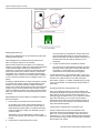
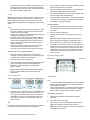
1
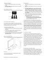
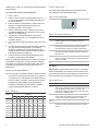
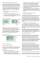
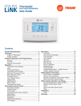
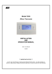
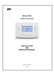
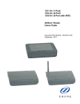
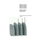
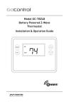
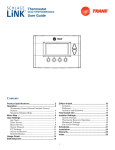
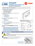
NX-592E NetworX Cellular Module Installation
Sheet
Part Number
Description
NX-592E-GSM-ZX-AT
NetworX Cellular Module, Alarm.com
HSPA 3G GSM with Z-wave, AT&T
NX-592E-GSM-ZX-RG
NetworX Cellular Module, Alarm.com
HSPA 3G GSM with Z-wave, Rogers
(Canada use only)
NX-592E-GSM-ZX-TM
NetworX Cellular Module, Alarm.com
HSPA 3G GSM with Z-wave, T-Mobile
NX-592E-CDMA-ZX-VZ
NetworX Cellular Module, Alarm.com
1xRTT CDMA with Z-wave, Verizon
Description
The NX-592E Cellular Module interfaces with the NetworX
panel data bus and is powered by the panel or an auxiliary 12
VDC power supply. Status LEDs indicate bus and cellular
network communications.
Figure 1 below shows the location of the main module
components and Table 1 below describes the component
functions.
Figure 1: Components
Serial Number Label
BUS LED
Antenna Jack
Gateway
Status LEDs
Z-wave Button
Wiring Terminals
Cellular Status LEDs
Wire Access Area
Mounting Holes
P/N 466-4435 • REV B • 18JUL13
Table 1: Components
Component
Function
BUS LED
Indicates data bus activity between the
panel and the bus module
Gateway Status
LEDs
Not Used
Wiring Terminals
Provides panel wiring connections
Antenna Jack
Antenna connection for snap-in MMCX
antenna
Cellular status LEDs
Indicates communication with the cellular
network, report errors and signal strength
Serial number
A 15-digit number. Only the last 10 digits
(after the dash “-“) are used for account
activation
Account creation
Before installing the Alarm.com cellular module in a NetworX
system, a new customer account needs to be created with
Alarm.com. We recommend creating the account at least 24
hours in advance of installation to ensure that the radio is
activated prior to installation.
To activate an account go to www.alarm.com/dealer and login.
Under the “Customers” heading at the top left of the page click
on “Create New Customer”. You will need the following
customer information to create the account:
•
•
•
•
•
•
Customer Name
Customer Address
Customer Phone Number
Customer E-mail
Preferred login name for the customer
Alarm.com Module Serial Number
At the end of the account creation process you will be able to
print a Welcome Letter for the customer that has their login
information and temporary password for the Alarm.com
website.
1
Installation Tips
•
Avoid mounting the module in areas with excessive metal
or electrical wiring, such as furnace or utility rooms.
Use the following tips to ensure success with the Alarm.com
NetworX cellular module:
•
Locate the module near an outside wall, preferably on an
upper level.
•
Make sure you create the customer account on the
Alarm.com dealer website at least 24 hours before
installation.
•
For homes or businesses located in canyons or with hills
nearby, it is necessary to place the antenna higher in the
building.
•
Use the Cellular Status LEDs on the module to check the
signal strength before you permanently mount the module.
•
NetworX panels support a maximum of one wireless
gateway per system.
•
Do a manual phone test to initiate communication (see
“Power up” on page 3).
Caution: You must be free of static electricity before handling
electronic components. Touch a grounded metal surface
before touching the circuit board.
To mount the module:
1.
Press down on the top of the enclosure cover, remove it,
and set it aside.
The module draws a maximum of 65 mA (continuous) from the
panel in power save mode, and 100 mA (continuous) from the
panel in idle and connected modes. The module can draw up
to 1600 mA (instantaneous peaks) from the panel. Do not
exceed the panel total output power when using panel power
for bus devices and hardwired sensors (refer to the panel
documentation).
2.
Snap the antenna onto the antenna connector (see
Figure 1 on page 1). To connect the antenna, place one of
your thumbs or fingers behind the antenna connector.
With your other hand, press the end of the micro miniature
coaxial connector (MMCX) into the antenna connector
until you hear a slight click.
3.
Place the back plate on the wall at the desired mounting
location, check for level, and mark the three mounting
holes and the wire access area (see Figure 1 on page 1).
Use three-conductor, 22 or 18 gauge stranded wire to connect
the module to the panel. Table 2 below shows the maximum
wire length for each gauge.
4.
To avoid placing unnecessary strain on the antenna
connector, which can damage the module, use either of
the following orientations shown in Figure 2.
Table 2: Maximum wire length
Figure 2: Antenna Routing
Installation
Gauge
Maximum wire length to panel
22 gauge
40 ft. (12.2 m)
18 gauge
90 ft. (27.4 m)
You will need the following tools and supplies to install the
module:
•
•
•
•
•
•
•
Small blade and Phillips screwdrivers
Drill and bits for screws and/or anchors
Wire cutter/stripper
Three-conductor, 22-gauge or larger stranded wire
#6 pan head screws (4 included)
Wall anchors (four included)
3.3-Kohm EOL resistors (included with main NX panel)
Use the following guidelines to choose a location for the
module:
•
•
2
Check the signal strength before choosing a location. Do a
walking signal strength test by powering the module off the
battery directly (connect the COM and POS terminals).
After 2 minutes, cellular status LED 4 will flash between
one and five times, where 5 indicates strongest signal
level. We recommend a signal level of two or higher.
Do not the mount the module inside the panel’s metal
enclosure.
Loop antenna and feed
-ORback through top of module
Feed antenna through wire
access area and into wall
5.
Set the back plate aside and drill holes at the mounting
and wire access area locations.
6.
Use wall anchors where studs are not present and secure
the back plate to the wall with the enclosed screws.
Wiring Connections
Caution: To prevent damaging the panel or module, you must
remove panel AC power and disconnect the backup battery
before making or changing wiring connections.
NX-592E NetworX Cellular Module Installation Sheet
To wire the module:
To power up:
1.
Remove AC panel power and disconnect the backup
battery.
1.
Verify that all wiring between the panel and module is
correct.
2.
Wire the module to the panel bus and power terminals
(see Figure 3 below).
2.
Connect the backup battery and restore AC power to the
panel.
3.
Verify that radio status LED 1 is not flashing any errors
(see Cellular Status LEDs on page 4). Also, verify that
LED 4 is flashing a cellular signal level of two or higher.
Otherwise, relocate the module. If LED 1 and LED 4 are
not flashing, and LED 2 and LED 3 are flashing together,
the module is in Power Save mode and the battery needs
to be charged.
4.
Perform a manual phone test by pressing *44 while the
system is disarmed (Make sure that panel’s Location 37,
Segment 2, Bit 7 is set).
Note: if Location 37, Segment 2, Bit 6 is set,
performing the phone test will trigger the local siren.
To avoid triggering the siren when performing the
phone test, make sure Bit 6 is OFF.
Figure 3: Wiring connections
POS COM DATA
Gateway
Panel
KP POS KP COM KP DATA
Case tamper switch (optional)
If the module is easily accessible, you can add case tamper
detection to activate an alarm or trouble (depending on panel
programming) when the cover is removed.
To install the tamper switch:
1.
Slide the reed switch into the plastic holder on the module
back plate.
2.
Connect a UL-Listed reed switch (with EOL resistor) to
any unused hardwired input on the panel.
3.
Insert the magnet into the nibs on the top cover and press
the magnet clip down over the magnet until it clicks into
place into the cover.
Figure 4: Case tamper switch
The panel will not show any indication that the phone test
signal has been sent. You can check the radio status LEDs L3
and L4: L4 should be blinking on for 2 seconds and off for 2
seconds. L3 will blink once briefly as soon as you press *44. If
the account is reporting to a Central Station, wait for a minute
and check with the Central Station to see if the phone test
signal was received correctly. The phone test is also used by
Alarm.com to set the module's parameters the first time the
module is powered up. It ensures that Alarm.com will receive
the sensors list and any other information required for proper
signaling.
Enrolling the module
The NetworX control panels automatically find and store in
memory the presence of all keypads, zone expanders, wireless
receivers, output modules, and any other device on the keypad
bus, allowing these devices to be supervised by the control
panel. To enroll the devices, enter Program Mode (refer to your
control panel documentation). When you exit Program Mode,
the control panel automatically enrolls the devices. This
process takes about 12 seconds. During this time, the Service
LED will illuminate and User codes will not be accepted. Once
a module is enrolled, if it is not detected by the control panel,
the Service LED will illuminate. When initially powering up, the
control panel automatically performs the device enrollment
process.
Programming using the keypad
Power up
You will need to power up the module and panel to start
communication between them.
NX-592E NetworX Cellular Module Installation Sheet
The wireless gateway needs to know the address of at least
one of the LCD keypads. Some commands, such as getting
the zone names for display on the website, will not work if the
keypad address is not known. By default, the wireless gateway
assumes a keypad address of 192 (keypad 1, partition 1). If
your LCD keypad is programmed differently (press *94 +
installer code to check), you must change the wireless gateway
keypad address.
To change the gateway keypad address:
1.
Press *, then 8.
2.
Enter the “Go to program” code (the default code is 9, 7, 1,
3). If the code is valid the keypad display will prompt you
for a device address.
3.
Enter the address of the NX-592E (7, 8) then press #. At
this point, the keypad display will prompt you for a
programming location to be entered.
4.
Enter 0, followed by the # key. Location 0, which is the
LCD address will display. The default is 192. For a list of
address, see Table 3 below.
5.
To change the LCD keypad address, enter the new
address, followed by the * key. The display will return to
the location prompt.
6.
To exit this location without changing the data, press the #
key.
7.
To review the data, repeat the above procedure, pressing
the * key without entering data first. If you attempt to
program an invalid entry for a particular segment, the
keypad sounder will emit a triple error beep and remain in
that segment waiting for a valid entry.
8.
Press the Exit key to exit this programming level. Press
the Exit key again to exit Program Mode.
While in programming mode and not in a location, the number
in parentheses is the location you were previously changing.
For example, if the display reads “Enter location, then # (2)”, it
is reminding you that location 2 was the last location you
programmed.
Location 0: LCD keypad address
Certain commands in the module require it to know the location
of at least one LCD keypad (if one exists in the system). If
your system has an LCD keypad we recommend that you
place it in Partition 1 Keypad 1. This will allow Location 0
to be left at the factory default. If the LCD keypad is
selected as something other than Partition 1 Keypad 1,
program the appropriate address in Location 0.
Cellular Status LEDs
The cellular radio status LEDs are five small LEDs located
near the bottom of the radio daughter board.
Figure 5: Cellular Status LEDs
Table 4: Cellular Status LED Functions
LED
Function
L1
Error LED. Flashes 1 to 8 times in an 8-second interval to
indicate a specific error. See Table 6 for errors and
common fixes.
L2
Panel Communication and Z-Wave status messages.
Flashes every time the module communicates with the
panel and flashes in patterns to indicate Z-Wave status.
L3
Cellular Communication. Flashes every time the cellular
signal level is checked and when packets are exchanged
with Alarm.com.
L4
Cellular Signal Level. Flashes 0 to 5 times to indicate signal
strength, or toggles on/off slowly when communicating with
Alarm.com servers.
L5
Z-Wave Error LED. See Table 7 for error descriptions.
LED Details
LED L1 (red). L1 flashes when there is an error. The number
of flashes indicates the error number. If there are two or more
errors at the same time, the errors will flash one after the other.
The LED will stay off for at least four seconds between errors.
Table 5: LED L1 errors
Flashes
Error
1
Module cannot communicate with the panel. Perform a
power cycle on the panel. If the error persists lift the module
out of the gateway and re-insert it. If the error is still
observed try a different module. Finally, if that does not fix
the problem try a different panel.
2
The SIM card is missing. The SIM card holder can be found
on the module. Verify that the SIM card holder is closed
securely and that there is a SIM card in the holder.
2 then 4
The module provisioning process could not be completed.
2 then 5
The module provisioning process could not be completed
because the module is currently roaming on the carrier’s
network.
Table 3: Addresses
Keypad
4
Partition
1
2
3
4
5
6
7
8
1
192
193
194
195
196
197
198
199
2
200
201
202
203
204
205
206
207
3
208
209
210
211
212
213
214
215
4
216
217
218
219
220
221
222
223
5
224
225
226
227
228
229
230
231
6
232
233
234
235
236
237
238
239
7
240
241
242
243
244
245
246
247
8
248
249
250
251
252
253
254
255
NX-592E NetworX Cellular Module Installation Sheet
Table 6: Z-wave LED Status Indicators
Flashes
Error
3
The module is trying to register on the cellular network. If it
persists for more than a few minutes, the module is having
problems registering with the network. Check L4 for signal
level. If signal level is lower than 2 “bars,” change the
module’s location or use a remote antenna option. If the
signal is good, the module may be roaming on a network
that does not partner with our providers, or the SIM card
was not activated yet because the Alarm.com account was
not created correctly.
LED
L2
4
The module is registered on the network, but cannot
connect with Alarm.com. Contact Alarm.com technical
support.
5
Radio portion of the module is not working correctly. If this
persists for more than a few minutes the module may need
to be replaced. This error is extremely rare so verify that the
module is flashing 5 times.
6
This is an error only if it persists for more than a minute.
Otherwise, it’s just an indication that the module is fixing an
unusual condition regarding communication with the
network.
7
There are bit sets in Location 21 that prevent Alarm.com
from getting the sensor list from the panel. In Location 21,
segment 1, if bits 5 and 6 are set the module cannot
retrieve the sensor list. Note that bit 7 will prevent location
21 from being displayed at the keypad. Bits 5, 6 and 7 can
only be set via the Downloader program.
This could also mean that the module is not compatible with
the current panel type..
8
If it persists, the account may have been set up incorrectly.
Contact Alarm.com Technical Support. You will be asked to
check the serial number of the module.
LED L2 (yellow). Flashes with every communication between
the module and the panel. Normal pattern calls for a series of
quick flashes every 2 seconds in idle mode or every 4 seconds
in power save mode. It also occasionally flashes in patterns to
indicate Z-wave status. See Table 6 below for a description of
various possibilities.
LED
L5
Device Status or
Error
Description
4-blink
Add mode (lasts
120 seconds or
until a device is
added)
In this mode you can add a
device to the local Z-Wave
network. Devices cannot
be added to a network if
they are already a part of a
network.
2-blink
Delete mode
(lasts 120
seconds or until a
device is deleted)
In this mode you can delete
a device from a Z-Wave
network. A device can only
be in one network at a
time, and must receive a
“delete” command before it
can be learned into a new
network.
Solid
Successful add
node/remove
node/ replication
(lasts 60 seconds)
After receiving this signal
leave all devices by the
cellular module for 1
minute. Locks must be left
next to the module for 4
minutes.
Solid
with
one
blink
Add node attempt
failed because
node already in
network (lasts 60
seconds)
The device you attempted
to add to a network is
already in a network, and
must be “deleted” before it
can join a new network.
2-blink
No other nodes
are in the network
(lasts until a
device is added to
the network)
No devices have been
added that can be
controlled by the cellular
module. See above for
instructions on how to add
devices.
5-blink
Learn mode error
(lasts 60 seconds)
The device you attempted
to add into a Z-Wave
network was not
successfully added.
6-blink
No Home ID
present (lasts until
the module
connects to
Alarm.com and is
configured)
When the cellular module
first connects to Alarm.com
it is configured with a
necessary unique network
ID.
LED L3 (yellow). Flashes with every communication between
the module and its radio unit in idle mode and with every
communication with Alarm.com in connected mode. In power
save mode, this LED flashes in unison with LED L2.
LED L4 (green). Indicates cellular signal level as a number of
flashes (0 to 5). The signal level is updated every 10 seconds if
it fluctuates or every 30 seconds if it is fairly stable.
No flashes indicate one of the following:
•
The module is in power save mode.
•
The module is just powering up, or has just exited power
save mode.
•
There is no carrier coverage in the area.
In connected mode, the LED toggles on and off.
LED L5 (yellow) Indicates Z-Wave errors. The possible
signals and what they indicate is shown in 6 below
NX-592E NetworX Cellular Module Installation Sheet
Module modes
The module modes (states) include:
Idle mode
AC power is up, the battery level is greater than 11.5 volts, and
the module is currently not connected to Alarm.com servers.
This is normal for the module and the most common state.
•
LED L1 flashes errors, if any.
•
LED L2 indicates communication with panel.
•
LED L3 indicates communication with radio unit.
•
LED L4 indicates the signal level (1 to 5 bars).
Power save mode
The module just powered up, AC power is down, or battery
level is less than 11.5 volts. The radio part of the module draws
10 mA in power save mode. It is fully functional and will go into
connected mode as soon as a signal needs to be sent. Doing a
manual phone test will switch the module into idle mode and
update the signal level reading.
•
LED L1 is inactive.
•
LED L2 indicates communication with panel.
•
LED L3 flashes in unison with LED L2.
•
LED L4 is inactive.
Connected mode
The module is connected to the Alarm.com servers and
reported an alarm or other condition. The module stays in
connected mode for at least 6 minutes after the last message
is exchanged. Entering the panel’s Installer Programming
mode will cause the module to go into idle mode.
•
•
•
•
LED L1 flashes errors, if any.
LED L2 indicates communication with panel.
LED L3 indicates communication with Alarm.com.
LED L4 alternates 2 seconds on, then 2 seconds off.
Module Troubleshooting Information
During account creation and other troubleshooting it may be
necessary to know the serial number, the SIM card number, or
the types of reports that the cellular module is allowed to
transmit. These can be found using the following procedure on
an LCD keypad (Skip this section if there is no LCD keypad
connected to the panel):
The cellular module will record its serial number, SIM card
number, or list of allowed reports into the name fields of zones
190, 191, and 192 of the LCD keypad. These zone names can
be viewed on any LCD keypad, even if the panel doesn't
support 192 zones. To access these zone names, press *92 +
installer code to enter Zone Name Programming Mode. Then
enter 192# for the module serial number, 191# for the SIM
number, or 190# for the reports list.
Table 7: Reporting Bits
B
Phone Test
M
Panel Programming
E
Alarms
N
Tamper
F
System Trouble
O
Cancels
G
Sensor Trouble
P
Normal Activity
H
Arming/Disarming
Q
Modem Online
J
Sensor Bypass
R
Pings
K
AC Power Failure
V
Panel Low Battery
L
Phone failure (phone failure will always be reported for
alarms and cancels)
Equipment List and Zones
On NX, the Alarm.com module cannot automatically determine
how many zones are installed. The module assumes that the
first 20 zones are installed by default. The module needs to
know the highest numbered zone installed in order to send an
accurate equipment list to Alarm.com. The equipment list is
used for alarm reporting to the Central Station and is displayed
on the Alarm.com websites.
The number of zones can be changed via one of these 4
methods:
•
Trip the highest zone installed (put the zone in alarm or
perform the Walk-Test procedure). This method can only
increase the number of zones. To decrease the number of
zones, use one of the alternative options below.
•
Send the “Highest Zone Number” command from the
Equipment page on the Dealer Web Site.
•
Enter the max zone number in location 189 of the main
LCD keypad (see procedure below).
•
Zones that are not installed should be skipped by setting
their partition to 0 (locations 26, 28, 32...) or else they will
By default, the keypad shows "Zone 190", "Zone 191", or
"Zone 192". To tell the cellular module to show its information
in place of these zone names, add a space in front of the zone
names by pressing the Stay button, followed by * and # to
validate the entry. When you are done with all 3 zones, press
Exit to leave programming mode.
be listed in the equipment list on the web site.
Within 1 to 2 minutes, the module will update the zone names
that start with a space with the required information. Zone 192
will show the updated serial number, zone 191 will show the
updated SIM card number, and zone 190 will show the
updated list of allowed reports. You can tell that the module
updated the fields by the fact that the leading space will have
been removed.
Alarms and troubles.
Table 7 describes the reporting bits as indicated in the text field
for zone #190:
6
Note: NX-8E supports up to 192 Zones. Alarm.com can
monitor any of the first 120 zones for Normal Activity (nonalarm sensor activity - subject to the limitations of the
Alarm.com service plan). All 192 zones are monitored for
Procedure for displaying or for changing the number of
zones via location 189 of an LCD keypad:
1. Type *92 + installer code to enter Zone Name
Programming
Mode.
NX-592E NetworX Cellular Module Installation Sheet
2.
Enter 189#.
3.
Press the STAY button to add a space at the beginning of
the zone name.
4.
Press * to validate the space.
5.
Press # and EXIT to exit Zone Name Programming Mode.
Bit 7: Interior zone – Bypass is sent only when panel is armed
away
Bit 8: Local zone – Bypass is never sent how the updated list
of allowed reports. You can tell that the module updated the
fields by the fact that the leading space will have been
removed.
Wait one minute and then repeat the steps above. You should
see “ZMAX:xxx”, with no space at the beginning, and with xxx
being the highest zone number that the cellular module is
going to list in the equipment list. To change this number of
zones, do the following:
Troubleshooting/Testing
1.
Press the STAY button to add a space at the beginning of
the zone name.
2.
Press * to move over the “:”
3.
Press “Chime” to remove the “:”
Check cellular status LED 4 for signal strength (if it is toggling
on and off it is connected). If signal strength is less than 2, do a
walking signal strength test (see Module Location Guidelines
on page 2).
4.
Press * to move over the digit you want to change.
5.
Press the up or down arrow to change the digit.
6.
Press * to validate the new digit.
7.
Repeat steps 4, 5, and 6 with the other digits.
8.
Press # and EXIT to exit Zone Name Programming Mode.
Within one minute, the cellular module will update its
equipment list according to the number of zones you specified.
This equipment list will be sent with the next phone test or
alarm.
Check the cellular status LED 1 to see if it is flashing any
errors. See Table 5 on page 5 for descriptions of the errors
indicated.
If touchpads/sirens are beeping even though the system is not
armed, press * 2 to display the trouble condition. Refer to
specific touchpad manual for more details.
Z-Wave devices
Required items for installation
•
NetworX panel (NX versions 4V2, 6V2, 8V2, 8E)
•
Alarm.com cellular Module with integrated Z-wave support
•
Z-Wave peripherals to be installed
Local Zones
Bit 8, segment 1 of the Zone Type Characteristic Select
locations determines whether the cellular module will report
alarms for this sensor type (See locations 111, 113, ..., 169).
Account creation and system setup
1.
Create a new account on the Alarm.com Dealer Site (or
swap the module into an existing customer account). Add
the appropriate emPower services (Lights, Thermostats,
and/or Locks) on the service plan page. (Note that “Light
Automation” refers to X10 and is not compatible with
emPower.)
2.
Install the Alarm.com Z-Wave-enabled cellular module and
gateway, connecting it to the NetworX panel.
3.
Perform a cellular test at the panel to initiate
communication between the module and Alarm.com.
If bit 8 is set, the panel and the module consider this sensor
type as “local” and will not report an alarm (The alarm will be
“reported” locally via the siren if so programmed).
Bypassed Zones
The cellular module will report bypass on a zone only when the
zone is in an “armed” state. The arming level of a zone is
determined by 4 bits of segment 1 of the Zone Type
Characteristic Select locations:
Bit 1: Fire zone – Bypass is sent regardless of panel arming
state
Bit 2: 24 Hour zone – Bypass is sent regardless of panel
arming state
NX-592E NetworX Cellular Module Installation Sheet
Make sure to install the Alarm.com module and gateway
outside the metal can. If it is inside the can, this will
negatively impact Z-Wave signal transmission.
Figure 6: Z-Wave module overview
Adding z-Wave devices
Once the module (or controller) is in Z-Wave Add mode,
press the appropriate buttons on the Z-Wave device to
add it to the network. See Device-specific instructions (or
the instructions that came with the device) for more
information.
Make sure the NetworX panel is connected to AC power when
enrolling Z-Wave devices.
When adding devices, first add the devices closest to the
Alarm.com system, and then move outwards.
Devices must be within 6 ft of the Alarm.com module when
adding it to the network. Install each of the Z-Wave peripherals
in their desired locations, following the manufacturer’s
instructions. Then follow the instructions to add (include) each
device into the Alarm.com module’s network. If a device will
not be within 6 ft. of the Alarm.com module in its permanent
installation location, include it in the network before installation
or use a controller (controllers are not available for locks, see
below).
If installing a portable Z-Wave controller, first add the controller
to the Alarm.com Z-Wave network using the NetworX panel,
and then use the portable controller to add the remaining
devices to the network while the devices are in their permanent
locations. (Locks cannot be added to the controller, and will
need to be added by the Alarm.com module.) Devices must be
within 6 ft. of the controller if a controller is being used to learn
in devices.
Add a Z-Wave device to the Alarm.com module’s network
(Device Inclusion)
1.
Put the Alarm.com module into Z-Wave Add mode.
On the Alarm.com module, press and hold down the ZWave Mode button for a few seconds, until the LED L2
begins flashing a 4-blink pattern to indicate Z-Wave Add
mode. (See Figure 6 on page 8) for illustration of how to
press the button.)
Alternatively, use a portable Z-Wave controller to add
devices to the network. (See the section on Controllers for
details).
2.
8
3.
Confirm the Z-Wave device is added successfully.
Once the device has been added successfully, the panel
will beep, and the yellow LED L2 will become solid and
stay solid for 1 minute (allow up to 5 seconds for
confirmation once the device has been triggered).
To add another device, repeat the steps above. (You do not
need to wait for the solid light to go away before holding down
the Alarm.com Z-Wave button to enter Add mode again.
See Table 6 on page 5 or “Z-Wave Troubleshooting” on page
12 for more information on interpreting the Z-Wave LEDs on
the module.
Checking the Devices list with Alarm.com
Once you’ve added the devices, the customer website will
automatically update the Devices list (under the emPower tab)
within about 2 minutes of the last device being added. (To
manually trigger the update sooner, you can perform a cellular
phone test at the panel.) You can also view the Z-Wave
devices through the Alarm.com Dealer website by pulling up
the customer account and clicking on the emPower Devices
link in the left-hand navigation.
Testing device communication with Alarm.com
Once the Z-Wave devices have been installed in their
permanent locations and are displayed in the device list on
Alarm.com, we recommend sending a remote command to
each device (e.g., turn on a light; adjust the target temperature
at a thermostat) to verify that it is successfully communicating
with the Alarm.com module.
Press buttons on the Z-Wave device to add.
NX-592E NetworX Cellular Module Installation Sheet
If you are onsite at the customer location and do not have
access to the website, you can also check communication
using the Z-Wave LED L2. When the Alarm.com module is in
Normal mode it is by default off, but issues a single flash
whenever it receives a message from a device in its own ZWave network. If a device is next to the panel, you can use this
feature to test whether or not the device is currently installed
on the Alarm.com Z-Wave network, and whether or not it is
communicating properly.
To check communication between a Z-Wave device and
the Alarm.com module:
1.
Ensure that the Z-Wave device is powered on, and then
press the same button you would use if you were trying to
add it to a network (check the device’s installation
instructions if you are unsure which button to press).
2.
The LED L2 on the module will issue a quick single flash
to indicate it has heard the signal form the device. If the
LED L2 does not flash when the device’s button is
pressed, this is most likely because of one of the following:
a) the device is not in the Alarm.com module’s Z-Wave
network; b) it is out of direct communication range from
the Alarm.com module; or c) the device is not powered on
or working properly.
Deleting a Z-Wave device (Device Exclusion)
You can enter Delete mode to:
•
•
Delete a Z-Wave device from the Alarm.com module’s ZWave network if you no longer want the device in the
network (e.g., if it is no longer in use).
Delete a Z-Wave device from a different network so that it
can then be added into the Alarm.com network. (A given
Z-Wave device can only be assigned to one Z-Wave
network at a time. If it is already assigned to one network,
it needs to be deleted from that network before it can be
added to another network.)
Whether you are deleting a device from the Alarm.com
module’s Z-Wave network or another Z-Wave network, the
steps are the same.
1.
2.
Put the Alarm.com module into Z-Wave Add mode.
If a device is no longer functioning, you can also delete it
through the Device Automation page on the Alarm.com Dealer
website. Send a remote command to the device and wait a few
minutes for the command to register as failed. The failed
device will have a remote node link next to it.
emPower on the Alarm.com Dealer website
Through the Alarm.com Dealer Website you can modify the
emPower service plan, view the Z-Wave device list, and order
emPower modules and devices. To add or remove emPower
features from your customer’s service plan, go to the
customer’s service plan page and check the features (lights,
locks, thermostat, or the energy package - lights and
thermostat) that you would like to add/remove. To view a list of
your customer’s Z-Wave devices, pull up their account and
click the “emPower Devices” link.
Device-specific instructions
Controllers
Advanced Remote Controller
Note: if a controller will be used with the system, Alarm.com
recommends adding it before the rest of the Z-Wave devices.
Refer to the instructions that came with your controller for more
information on controller features and operation.
To add the controller to the security panel (system):
1.
Enter your panel into Add mode.
2.
With the controller close to your panel, press and hold the
Setup button on the controller until the controller screen
displays “Lights Setup”.
3.
Use the arrow buttons to scroll until you see “Transfer” on
the controller screen. Press the OK button.
4.
The controller screen should now display “Primary”. Use
the arrow buttons to scroll until you see “Receive”.
5.
Press the OK button. The controller screen should display
“Receiving”.
6.
The controller screen will briefly display “Success” after
the controller has been successfully included into the
panel.
On the Alarm.com module, press and hold down the ZWave Mode button to enter Add mode (4-blink pattern on
the LED L2). Once in Add mode, press and hold down the
Z-Wave Mode button again until the LED L2 begins
flashing a 2-blink pattern to indicate Z-Wave Delete mode.
(See Figure 6 on page 8 for illustration of how to press the
button.)
To add a light module to the system using the controller:
1.
Press and hold the Setup button on the controller until the
screen displays “Light Setup”. Press the OK button.
Press buttons on the Z-Wave device to delete.
2.
The controller screen should now display “Add”. Press the
OK button.
3.
The controller screen should now display “To Network”.
4.
Use the arrow buttons to scroll until you see “To a Key”
and then press the OK button.
5.
Press a number key 1 to 9 or Setup (Shift) and a number
key for numbers 10 to 18.
6.
Press the OK button and the screen should now display
“Setup Waiting”.
7.
Double-click the button on the light module. The controller
screen will briefly display “Success” to confirm you have
Once the module (or controller) is in Z-Wave Delete mode,
press the appropriate buttons on the Z-Wave device to
delete it from the network. See Device-specific instructions
(or the instructions that came with the device) for more
information.
3.
Confirm the Z-Wave device was deleted successfully.
4.
Once the device has been deleted successfully, the panel
will beep, and the yellow LED L2 on the Alarm.com
module’s Z-Wave board will become solid and stay solid
for 1 minute (allow up to 5 seconds for confirmation once
the device has been triggered).
NX-592E NetworX Cellular Module Installation Sheet
added the device to the controller key and system
network.
Note: To add a light module using the controller without adding
it to a specific number key on the controller, skip steps 4 and 5.
To add a thermostat to the system using the controller:
1.
Press and hold the Setup button on the controller until the
screen displays “Light Setup”.
2.
Use the arrow buttons to scroll until the screen displays
“Thermostat”. Press the OK button.
3.
The screen should now display “Add”. Press the OK
button.
4.
The screen should now display “Setup Waiting”. Follow
the device-specific directions for the thermostat you are
adding to the system to trigger it. The controller screen will
display “Success” to confirm you have successfully added
it to the system network.
To remove a light module from the system network using
the controller:
1.
Press and hold the Setup button on the controller until the
screen displays “Light Setup”. Press the OK button.
2.
The controller screen should now display “Add”. Use the
arrow buttons to scroll until you see “Delete”. Press the
OK button.
3.
Double-click the button on the light module. The controller
screen will briefly display “Success” to confirm you have
removed the device from the controller key and system
network.
To remove the thermostat from the system network using
the controller:
1.
Press and hold the Setup button on the controller until the
screen displays “Light Setup”. Press the OK button.
2.
Use the arrow buttons to scroll until the screen displays
“Thermostat”. Press the OK button.
3.
The controller screen should now display “Add”. Use the
arrow buttons to scroll until you see “Delete”. Press the
OK button. The screen should now display “Setup
Waiting”.
4.
Follow the device-specific directions for the thermostat
that you are removing from the system to trigger it.. The
controller screen will briefly display “Success” to confirm
you have removed it from the system network.
To delete the controller from the security panel (system):
1.
Enter your panel into Delete mode.
2.
Follow steps 2 to 5 in the instructions for “To add the
controller to the security panel (system):” on page 9.
3.
The controller screen will briefly display “Success” after
the controller has been successfully deleted from the
panel.
Lights and appliances
Plug-in Lamp Module or Plug-in Fluorescent
Light/Appliance Module
1.
Plug in the device.
2.
Enter Add mode on the security panel.
3.
To add the device, double-click the button in the middle of
the light or appliance module. (If there is no beep at the
panel confirming successful enrollment of the device, try
pressing the button again.)
Tips
•
•
•
•
•
In-Wall Dimmer Light Switch or In-Wall On/Off Light Switch
1.
Follow the provided directions to install the device and
ensure that it functions properly with manual on/off control.
2.
Enter Add mode on the security panel.
3.
To add the device, turn on and turn off the light switch. (If
there is no beep at the panel confirming successful
enrollment of the device, try turning the device on and off
again.)
Tips
•
•
Dimmer switches and on/off switches cannot be
interchanged. Use the appropriate type of switch.
If it is not practical to move the security panel 3 to 6 ft. to
the device, consider investing in a controller for
installations.
In-Wall Outlet Receptacle
1.
Follow the provided directions to install the device and
ensure that it functions properly with manual control.
2.
Enter Add mode on the security panel.
3.
To add the device, double-click the button in the middle of
the outlet. (If there is no beep at the panel confirming
successful enrollment of the device, try double-clicking the
button again.)
Tips
•
•
10
Lamp modules cannot be used with compact fluorescent
bulbs (CFBs). Use appliance modules instead.
Make sure the lamp to be controlled is plugged into the ZWave side of the module (indicated by the Z-Wave logo).
We recommend using a non-switched outlet for the
module. If using an outlet controlled by a switch, make
sure the outlet is switched on before sending light
commands.
Keep lamps switch on to allow control through the Z-Wave
module, Alarm.com website, and mobile applications.
Control dimming of lamp modules by pressing and holding
the button on the module, or through the Alarm.com
website
If it is not practical to move the security panel 3 to 6 ft. to
the device, consider investing in a controller for
installations.
We recommend using a non-switched outlet for the ZWave outlet. If using a switch outlet, make sure the outlet
is switched on before sending commands.
NX-592E NetworX Cellular Module Installation Sheet
•
1.
Enter the panel into Delete mode (see “Deleting a Z-Wave
device (Device Exclusion)” on page 9).
2.
Enter the six-digit programming code on the keypad and
wait for three orange lights and three beeps.
3.
Press the Schlage button and then 0 on the keypad. Wait
for three orange lights and three beeps.
Note: If the security panel cannot be taken to within 6 ft. of the
lock installation location, add the lock to the system first as
directed beginning in step 2. (You will need to connect the
battery pack to the keypad before attempting to perform these
steps.)
4.
Wait for all lights to stop blinking. You should now be able
to enroll the lock normally by repeating the steps shown
above (after re-entering Add mode).
Tips
1.
Follow all instructions provided to install the lock onto the
door and double-check that the programmable keypad
lock works.
2.
Enter the panel into Add mode.
3.
To trigger the lock to add it, press button “B” (Figure 8
below).
Only the lower outlet is controlled by Z-Wave. Ensure you
are plugging devices into the lower outlet while testing if
the outlet works for Z-Wave control. The opposite is true if
the device is installed upside down.
Locks
•
•
•
•
Before removing old locks or beginning installation, check
the layout of the door to make sure the new lock will not
conflict with existing hardware.
Contact a locksmith if you experience difficulties removing
old hardware or installing the new lock.
Send user codes to the lock (via the customer website see step 4) before leaving the property. Alarm.com does
not recommend programming codes locally via the lock
keypad - all codes should be programmed through the
Alarm.com interface.
Ask your customer to save the programming code that
comes with the lock (Schlage only). This will be
convenient to have if they ever have issues in the future.
Kwikset deadbolt
Note: Wait until the red light (under the paper next to
button “B”) stops flashing before disrupting the lock or
panel. Failure to do so will result in lock malfunctions.
4.
Schlage lever lock or Schlage deadbolt
1.
Follow the instructions included with the lock. When
prompted to continue setup online, do the following steps
to program the lock into the Concord panel.
2.
Enter Add mode on the security panel.
3.
On the lock keypad, enter the six-digit programming code
(given by Schlage), then press the Schlage button,
followed by 0. The Schlage button will flash green
(Figure 7 below).
Login online to the customer account at www.Alarm.com
to select which user codes are allowed to use this lock. To
do this, go to the emPower then Locks tab. On the User
Codes table, you will see a column labeled Lock Access.
Check the box of the lock you want to allow each user
code to access.
Figure 8: Lock trigger button
Note: Wait until the light flashes green before disrupting
the lock or panel. Failure to do so will result in lock
malfunctions.
Figure 7: Schlage lock
Thermostats
Tips
•
•
4.
Login online to the customer account at www.alarm.com to
select which user codes are allowed to use this lock. To
do this, go to the emPower then Locks tab. On the User
Code table, you will see a column labeled Lock Access.
Check the box of the lock you want to allow each user
code to access.
Tip
If you observe a red blinking light at the end of the installation
keystrokes instead of green, follow these instructions:
The new thermostat should be placed in the same location
as the original thermostat unless an HVAC professional
approves the new location.
Learn the thermostat into your emPower network while it is
powered using the power source (AC power vs. battery
power) it will use during regular use after installation.
UTC Z-Wave Thermostat
1.
Follow the manufacturer’s instructions to install the
thermostat.
2.
Enter Add mode on your panel.
3.
Under the top cover of the thermostat, press the black
Mate button located in the upper right hand side.
Note: The thermostat should be connected to AC before it
is learned into the network.
NX-592E NetworX Cellular Module Installation Sheet
Trane Remote Energy Management Thermostat
Note: The Trane thermostat requires a 24 VAC common wire
to power the thermostat. Before beginning installation, verify
the HVAC system has a common wire or contact a qualified
HVAC technician. If the security panel cannot be taken to
within 6 ft of the thermostat installation location and you do not
have a portable controller, power the thermostat temporarily
using a 24 volt transformer and add the thermostat to the
system as described in steps 2 and 3 before installing the
thermostat.
1.
Follow the instructions included with the thermostat
through step 19.
2.
Instead of step 20, enter Add mode on your panel.
3.
Hit the Menu button on the thermostat panel. Scroll down
to Z-Wave Install and press Select (Figure 9 below). Press
the Yes button to enroll the thermostat.
Figure 9: Trane thermostat
•
•
Increasing wireless range of device network
•
Verify the enrollment of the thermostat. Scroll down to
Thermostat Info and press the Select button. Look at the
number listed after ZNID. If the number listed is anything other
than 000, the thermostat was successfully enrolled. If the
number listed is 000, then the thermostat has not been
successfully enrolled. Try enrollment again or verify that the
thermostat is not currently part of another network.
Expand your network in pairs:
If a device has been added successfully but does not appear to
be communicating reliably with the system, it may be
necessary to place another Z-Wave device (that’s already on
the network) between the panel and the problem device, to
serve as a repeater that can relay messages between the two.
We recommend expanding your network in pairs of devices.
More devices allow for multiple Z-Wave communication paths,
preventing any one device from becoming a bottleneck in the
network.
•
Tip
(excluding) it from its network and the try adding it again. If
you receive a Timeout/Error message when trying to
delete the device, the issue is likely range-related.
If the device is too far from the Alarm.com module when
you are adding it, you may need to move the device closer
to the panel (or vice versa) while adding it, or else use a
portable controller to add it.
Other 900 MHz wireless devices may be interfering with
the Z-Wave messages. Try moving or replacing any 900
MHz headsets, cordless phones, baby monitors, wireless
speaker extenders, IR remote control extenders, or similar
devices.
Expand your network using beaming devices:
Locks and battery-powered thermostats enter sleep mode to
conserve battery life, and therefore can only communicate
directly with the panel or with beaming devices that can send a
wake-up message. In general, devices powered off of batteries
do not beam, and most (but not all) devices powered off of AC
power beam.
Note: Newer light/appliance modules support beaming, but
some earlier versions did not. To find out if a given module is
beaming-compatible, check the label. The light/appliance plugin module supports beaming if the date code starts with 11 or
the version includes the letter a or the letter b.
Lock not securely enrolled
Figure 10: Verify enrollment
Lock devices must complete a secure enrollment process
during addition, which can take up to a minute to complete
while the lock is within 6 ft. of the panel. If this process is
interrupted before completing, the lock will not function
properly. A warning message will display on the Alarm.com
customer site and on the Dealer site that secure enrollment is
not complete. The lock should be deleted from the network and
re-added, making sure to allow enough time for secure
enrollment to complete before disrupting the lock or panel.
No Home ID (6 flashes on Z-Wave LED L5)
Z-Wave Troubleshooting
Try the following troubleshooting steps:
This error occurs when the Alarm.com module has not
received the Z-Wave “Home ID”. Usually, this occurs when the
module has not yet communicated with Alarm.com since the
Home ID is sent during initial communication. Perform the
CDMA phone test and confirm that communication between
Alarm.com and the module has been initiated. If the module is
already communicating with Alarm.com and this error persists,
check that the Z-Wave daughterboard is securely connected to
the module and power cycle the unit.
•
Device already in Network (steady LED L2 with one blink)
Device not added successfully
If there is an error, or the two-minute time limit expires when
adding a device, LED L5 will issue a 5-blink, and the LED L2
will never light up to indicate that the device was added
successfully.
12
The device may already be part of a Z-Wave network
(whether or not you have learned the device into a
network or not, the manufacturer may have tested the
device and left it learned into another system). Try deleting
The device being added is already part of a Z-Wave network
(whether the existing network or an old network) and cannot be
NX-592E NetworX Cellular Module Installation Sheet
added again. Clear the device by deleting (excluding) it from its
network.
Note: The Alarm.com module can be used to delete devices in
any network. The device will clear itself and be able to be
added to another network. The device’s old network will still list
that device as part of its network (but the device will not be
able to be controlled by that network) until the device is
removed from its old network.
encouraged to try to correct the interference by one or more of
the following measures:
• Reorient or relocate the receiving antenna.
• Increase the separation between the equipment and receiver.
• Connect the equipment in to an outlet on a circuit different from that
which the receiver is connected.
• Consult the dealer or an experienced radio/TV technician for help.
Specifications
Compatibility
NetworX panels: NX V2 4, 6, 8 and 8E.
(Note: certain older V1 NX4, 6 and 8 may
not be fully supported).
Voltage
9.5 to 15 VDC, 12 V nominal, 65 mA
(continuous), 1600 mA (instantaneous
peak), maximum from panel or auxiliary
power supply
Cellular network
1xRTT CDMA Verizon; 3G HSPA AT&T, TMobile or Rogers
Power/data bus
One 3-wire NetworX power/communication
data bus
Indicators
One module/panel communication status
LED, one module power LED, one
automation LED, three wireless
communication status LEDs, and 4 GSM
status LEDs
Dimensions
5.25 × 4.125 × 1 in. (133 × 105 × 25 mm)
Case color
Belgian gray
Case material
High-impact, ABS plastic
Operating temperature
32 to 120ºF (0 to 49ºC)
Storage temperature
-30 to 140ºF (-34 to 60ºC)
Relative humidity
90% noncondensing (maximum)
Regulatory information
FCC
Changes or modifications not expressly approved by UTC Fire
and Security can void the user’s authority to operate the
equipment.
This equipment has been tested and found to comply with the
limits for a Class B digital device, pursuant to part 15 of the
FCC Rules. These limits are designed to provide reasonable
protection against harmful interference in a residential
installation. This equipment generates, uses, and can radiate
radio frequency energy and, if not installed and used in
accordance with the instructions, may cause harmful
interference to radio communications.
However, there is no guarantee that interference will not occur
in a particular installation. If this equipment does cause harmful
interference to radio or television reception, which can be
determined by turning the equipment off and on, the user is
NX-592E NetworX Cellular Module Installation Sheet
This equipment complies with the FCC RF radiation exposure
limits set forth for an uncontrolled environment. This equipment
should be installed and operated with a minimum distance of
20 centimeters between the radiator and your body.
Under Industry Canada regulations, this radio transmitter may
only operate using an antenna of a type and maximum (or
lesser) gain approved for the transmitter by Industry Canada.
To reduce potential radio interference to other users, the
antenna type and its gain should be so chosen that the
equivalent isotropically radiated power (e.i.r.p.) is not more
than that necessary for successful communication.
Conformément à la réglementation d'Industrie Canada, le
présent émetteur radio peut fonctionner avec une antenne d'un
type et d'un gain maximal (ou inférieur) approuvé pour
l'émetteur par Industrie Canada. Dans le but de réduire les
risques de brouillage radioélectrique à l'intention des autres
utilisateurs, il faut choisir le type d'antenne et son gain de sorte
que la puissance isotrope rayonnée équivalente (p.i.r.e.) ne
dépasse pas l'intensité nécessaire à l'établissement d'une
communication satisfaisante.
This device complies with Industry Canada license-exempt
RSS standard(s).
Operation is subject to the following two conditions: (1) this
device may not cause interference, and (2) this device must
accept any interference, including interference that may cause
undesired operation of the device.
Le présent appareil est conforme aux CNR d'Industrie Canada
applicables aux appareils radio exempts de licence.
L'exploitation est autorisée aux deux conditions suivantes: (1)
l'appareil ne doit pas produire de brouillage, et (2) l'utilisateur
de l'appareil doit accepter tout brouillage radioélectrique subi,
même si le brouillage est susceptible d'en compromettre le
fonctionnement.
FCC ID: YL6-143200H5V4 (GSM), YL6-143200C5V4 (CDMA)
IC: 9111A-143200H5V4 (GSM)
Contact information
www.utcfireandsecurity.com or www.interlogix.com
For customer support, see www.interlogix.com/customersupport
Copyright © 2013 UTC Fire & Security. All rights reserved