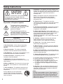
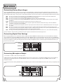
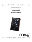
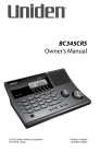
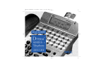
1
a
u
s
m
a
n
Dual EQ Design with Slider LED's and EQ On/Off Toggle Button
10-Band EQ for Music Channels and 5-Band EQ for Microphone Channels
Digital Echo, Repeat and Delay Controls with Separate Mic Channel Echo Level
Controls
Two 1 / 4" Microphone Inputs with Individual Volume Controls
Gain Pad for On-the-fly Mic Channel Boosting
Large Stereo Spectral Analyzer with Normal and Reverse Display Modes
Pink Noise Generator for Performance Testing and Diagnostics
Two RCA-style Audio Input Channels for Source Devices
One RCA-style Mic-Only Audio Output Channel for Dedicated Vocal Output
Two RCA-Style Audio Outputs (REC and Pre-out) for External Amps, Recorders and
Mixers
Sleek, Roadworthy Two Space Rack-Mountable Construction
l
Featur es:
SPECTRUM GRAPHIC EQUALIZER ANALYZER
EQ
DISPLAY
MIC EQ
MIC EFFECT
MASTER
'
10-Band Stereo Equalizer
DA-900
r
DIGITAL KARAOKE
MIXER WITH EQ
MIC1/VOL
POWER
MIC1
NORMAL
GAIN
CDG
PINK NOISE
OFF
ON
MIC2/VOL
NORMAL REVERSE
o
w
n
DVD
MIC2
DISPLAY MODE
e
EQ MODE
INPUT
DA-900
Digital Karaoke Mixer
W ith Dual Equalizers
Safety Instructions
CAUTION
RISK OF SHOCK
CAUTION: To reduce the risk of electric shock,
do not remove cover (or back). No userserviceable parts inside. Only refer servicing to
qualified service personnel.
Explanation of Graphical Symbols
The lightning flash & arrowhead
symbol, within an equilateral triangle,
is intended to alert you to the
presence of danger.
The exclamation point within an
equilateral triangle is intended to alert
you to the presence of important
operating and servicing instructions.
WARNING
To reduce the risk of fire or electric shock, do
not expose this unit to rain or moisture.
8. Ventilation - The appliance should be situated so its
location does not interfere with its proper ventilation. For
example, the appliance should not be situated on a bed,
sofa, rug, or similar surface that may block the
ventilation slots.
9. Heat - The appliance should be situated away from
heat sources such as radiators, heat registers,
stoves, or other appliances (including amplifiers)
that produce heat.
10. Power Sources - The appliance should be
connected to a power supply only of the type described
in the operating instructions or as marked on the
appliance.
11. Grounding or Polarization - Precautions should be
taken so that the grounding or polarization means of
an appliance is not defeated.
12. Power-Cord Protection - Power-supply cords
should be routed so that they are not likely to be walked
on or pinched by items placed upon or against them,
paying particular attention to cords at plugs,
convenience receptacles, and the point where they exit
from the appliance.
13. Cleaning - Unplug this unit from the wall outlet
before cleaning. Do not use liquid cleaners or
aerosol cleaners. Use a damp cloth for cleaning.
14. Power lines - An outdoor antenna should be
located away from power lines.
1. Read Instructions - All the safety and operating
instructions should be read before the appliance is
operated.
15. Nonuse Periods - The power cord of the appliance
should be unplugged from the outlet when left unused
for a long period of time.
2. Retain Instructions - The safety and operating
instructions should be retained for future reference.
16. Object and Liquid Entry - Care should be taken so
that objects do not fall and liquids are not spilled into the
enclosure through openings.
3. Heed Warnings - All warnings on the appliance and in
the operating instructions should be adhered to.
4. Follow Instructions - All operating and use
instructions should be followed.
5. Attachments - Do not use attachments not
recommended by the product manufacturer as they may
cause hazards.
6. Water and Moisture - Do not use this unit near water.
For example, near a bathtub or in a wet basement and
the like.
7. Carts and Stands - The appliance should be used
only with a cart or stand that is recommended by the
manufacturer.
7 A. An appliance and cart combination
should be moved with care. Quick stops,
excessive force, and uneven surfaces may
cause an overturn.
1
17. Damage Requiring Service - The appliance should
be serviced by qualified service personnel when:
A.
B.
C.
D.
The power supply cord or plug has been damaged; or
Objects have fallen into the appliance; or
The appliance has been exposed to rain; or
The appliance does not appear to operate normally
or exhibits a marked change in performance; or
E. The appliance has been dropped, or the enclosure
damaged.
18. Servicing - The user should not attempt to service
the appliance beyond that described in the operating
instructions. All other servicing should be referred to
qualified service personnel.
Note:
To CATV system installer's (U.S.A.): This reminder is
provided to call the CATV system installer's attention to
Article 820-40 of the NEC that provides guidelines for
proper grounding and, in particular, specifies that the
cable ground shall be connected as close to the point of
cable entry as practical.
SAFETY INFORMATION (U.S.A.)
1. IMPORTANT NOTICE: DO NOT MODIFY THIS
UNIT!: This product, when installed as indicated in the
instructions contained in this manual, meets Q.C.
requirements. Modifications not expressly approved by
Vocopro may void your warrenty.
2. IMPORTANT: When connecting this product to
accessories and/or another product use only high
quality shielded cables. Cable(s) supplied with this
product MUST be used. Follow all installation
instructions.
3. NOTE: This equipment generates/uses radio
frequencies and, if not installed and used according to
the instructions found in the owner's manual, may cause
interference harmful to the operation of other electronic
devices. If this product is found to be the source of
interference, which can be determined by turning the
unit "Off" and "On", please try to eliminate the problem
by using one of the following measures:
Relocate either this product or the device that is being
affected by the interference.
Use power outlets that are on different branch (circuit
breaker or fuse) circuits or install AC line filter(s).
CAUTION:
READ THIS BEFORE OPERATING YOUR UNIT
1. To ensure the finest performance, please read this
manual carefully. Keep it in a safe place for future reference.
2. Install your unit in a cool, dry, clean place - away from
windows, heat sources, and too much vibration, dust,
moisture or cold. Avoid sources of hum (transformers, v
motors). To prevent fire or electrical shock, do not expose to
rain and water.
3. Do not operate the unit upside-down.
4. Never open the cabinet. If a foreign object drops into the
set, contact your dealer.
5. Place the unit in a location with adequate air circulation.
Do not interfere with its proper ventilation; this will cause the
internal temperature to rise and may result in a failure.
6. Do not use force on switches, knobs or cords. When
moving the unit, first turn the unit off. Then gently disconnect
the power plug and the cords connecting to other
equipment. Never pull the cord itself.
7. Do not attempt to clean the unit with chemical solvents:
this might damage the finish. Use a clean, dry cloth.
In the case of radio or TV interference, relocate/reorient
the antenna. If the antenna lead-in is 300-ohm ribbon
lead, change the lead-in to coaxial type cable.
8. Be sure to read the "Troubleshooting" section on common
operating errors before concluding that your unit is faulty.
If these corrective measures do not produce satisfactory
results, please contact your local retailer authorized to
distribute Vocopro products. If you can not locate the
appropriate retailer, please contact Vocopro, 1728
Curtiss Court, La Verne, CA 91750.
9. This unit consumes a fair amount of power even when the
power switch is turned off. We recommend that you unplug
the power cord from the wall outlet if the unit is not going to
be used for a long time. This will save electricity and help
prevent fire hazards. To disconnect the cord, pull it out by
grasping the plug. Never pull the cord itself.
10. To prevent lightning damage, pull out the power cord
and remove the antenna cable during an electrical storm.
11. The general digital signals may interfere with other
equipment such as tuners or receivers. Move the system
farther away from such equipment if interference is
observed.
CAUTION
The apparatus is not disconnected from the AC power
source so long as it is connected to the wall outlet,
even if the apparatus itself is turned off. To fully insure
that the apparatus is indeed fully void if residual power,
leave unit disconnected from the AC outlet for at least
fifteen seconds.
NOTE:
Please check the copyright laws in your country
before recording from records, compact discs,
radio, etc. Recording of copyrighted material may
infringe copyright laws.
2
Welcome...
And Thank you for purchasing the DA-900 from VocoPro, your ultimate choice in
Karaoke entertainment! With years of experience in the music entertainment business,
VocoPro is a leading manufacturer of Karaoke equipment, and has been providing
patrons of bars, churches, schools, clubs and individual consumers the opportunity to
sound like a star with full-scale club models, in-home systems and mobile units. All our
products offer solid performance and sound reliability, and to further strengthen our
commitment to customer satisfaction, we have customer service and technical support
professionals ready to assist you with your needs. We have provided some contact
information for you below.
VocoPro
1728 Curtiss Court
La Verne, CA 91750
Toll Free: 800-678-5348
TEL: 909-593-8893
FAX: 909-593-8890
VocoPro Company Email Directory
Customer Service & General Information
[email protected]
Tech Support
[email protected]
Remember Our Website
Be sure to visit the VocoPro website www.vocopro.com for the latest information on
new products, packages and promos. And while you're there don't forget to check out
our Club VocoPro for Karaoke news and events, chat rooms, club directories and even a
KJ Service directory!
We look forward to hearing you sound like a PRO, with VocoPro, your ultimate choice in
Karaoke entertainment.
FOR YOUR RECORDS
Please record the model number and serial number below, for easy reference, in case of loss or theft. These numbers
are located on the rear panel of the unit. Space is also provided for other relevant information
Model Number
Serial Number
Date of Purchase
Place of Purchase
3
DA-900
Digital Karaoke Mixer with Dual Equalizers
Contents
Specifications
Introduction
Safety Instructions..............................
Welcome……………………………….
Specifications.....................................
Listening For a Lifetime………………
1-2
3
4
5
Before Getting Started
Unpacking..........................................
Mounting............................................
6
6
Getting Connected
Source Inputs.....................................
Pre-Out..…….....................................
Line Out.............................................
Music Out...……................................
Mic Out..............................................
Mic Inputs..........................................
Powering Up......................................
Sound Check.....................................
7
7
8
8
8
9
9
9
Controls and Functions
Front Panel.........................................
Rear Panel………………………….....
10
11
Operations
Source Music Output...........………….
Digital Echo Settings...........................
Microphone Output.............................
12
12
12
POWER CONSUMPTION
10W
INPUT SENSITIVITY
65mV
S/N RATIO
78 - 5dB/80dB (0-55mV)
FREQUENCY RESPONSE
30Hz - 16kHz
FREQUENCY LIMITATION
30Hz
60Hz
120Hz
240Hz
480Hz
1kHz
2kHz
4kHz
8kHz
16kHz
+/- 7dB - 5dB
+/- 7dB - 5dB
+/- 7dB - 5dB
+/- 7dB - 5dB
+/- 7dB - 5dB
+/- 7dB - 5dB
+/- 7dB - 5dB
+/- 7dB - 5dB
+/- 7dB - 5dB
+/- 7dB - 5dB
POWER INPUT
110V-240V
INPUT SENSITIVITY
50mV
ACCESSORIES
Operating Instructions
Warranty Card
1
1
4
Listening For A Lifetime
Selecting fine audio equipment such as the unit you've just purchased is only the start of your musical enjoyment. Now it's
time to consider how you can maximize the fun and excitement your equipment offers. VocoPro and the Electronic
Industries Association's Consumer Electronics Group want you to get the most out of your equipment by playing it at a
safe level. One that lets the sound come through loud and clear without annoying blaring or distortion and, most
importantly, without affecting your sensitive hearing.
Sound can be deceiving. Over time your hearing 'comfort level' adapts to a higher volume of sound. So what sounds
'normal' can actually be loud and harmful to your hearing. Guard against this by setting your equipment at a safe level
BEFORE your hearing adapts.
To establish a safe level:
• Start your volume control at a low setting.
• Slowly increase the sound until you can hear it comfortably and clearly, and without
distortion.
Once you have established a comfortable sound level:
• Set the dial and leave it there.
• Pay attention to the different levels in various recordings.
Taking a minute to do this now will help to prevent hearing damage or loss in the future. After all, we want you listening for
a lifetime.
Used wisely, your new sound equipment will provide a lifetime of fun and enjoyment. Since hearing damage from loud
noise is often undetectable until it is too late, this manufacturer and the Electronic Industries Association's Consumer
Electronics Group recommend you avoid prolonged exposure to excessive noise. This list of sound levels is included for
your protection.
Some common decibel ranges:
Level
30
40
50
60
70
80
Example
Quiet library, Soft whispers
Living room, Refrigerator, Bedroom away from traffic
Light traffic, Normal Conversation
Air Conditioner at 20 ft., Sewing machine
Vacuum cleaner, Hair dryer, Noisy Restaurant
Average city traffic, Garbage disposals, Alarm clock at 2 ft.
The following noises can be dangerous under constant exposure:
Level
90
100
120
140
180
Example
Subway, Motorcycle, Truck traffic, Lawn Mower
Garbage truck, Chainsaw, Pneumatics drill
Rock band concert in front of speakers
Gunshot blast, Jet plane
Rocket launching pad
-Information courtesy of the Deafness Research Foundation
5
Before Getting Started
Thank you for purchasing the DA-900 Digital Karaoke Mixer with Dual Equalizers. We know the DA-900 will provide years of highquality enjoyment and reliable music entertainment for you when used properly. Please read this manual carefully before using your
new DA-900 to ensure best performance.
Unpacking the DA-900
Carefully remove the DA-900 from its carton. It is recommended that the original packaging materials be retained, should it become
necessary to return the product for any reason.
Be Sure You Have the Parts and Components Included with theDA-900:
Parts
1- DA-900
1- RCA Patch Cable
EQ
DISPLAY
SPECTRUM GRAPHIC EQUALIZER ANALYZER
10-Band Stereo Equalizer
MIC EQ
MIC EFFECT
MASTER
DA-900
DIGITAL KARAOKE
MIXER WITH EQ
MIC1/VOL
POWER
EQ MODE
INPUT
DVD
CDG
PINK NOISE
OFF
ON
MIC1
NORMAL
MIC2
MIC2/VOL
DISPLAY MODE
NORMAL REVERSE
Mounting the DA-900
To mount, carefully place the DA-900 Pro in the 2 rack-space area of your case. The DA-900 Pro takes 4 screws to
mount. Make sure holes are aligned evenly. Use an alternating “X” rotation when screwing to ensure even tension and
alignment.
Side Mounting
SPECTRUM GRAPHIC EQUALIZER ANALYZER
10-Band Stereo Equalizer
EQ
DISPLAY
MIC EQ
MIC EFFECT
MASTER
DA-900
DIGITAL KARAOKE
MIXER WITH EQ
MIC1/VOL
POWER
EQ MODE
INPUT
DVD
CDG
PINK NOISE
OFF
ON
MIC1
NORMAL
MIC2
MIC2/VOL
DISPLAY MODE
NORMAL REVERSE
6
Getting Connected
The DA-900 has two audio input channels for source players. Each device connection will require one RCA-type stereo patch cable.
To connect the source players, follow the steps below:
(a) Connect an RCA-type stereo patch cable from the AUDIO OUTPUT jacks on the SOURCE PLAYER to either of the two AUDIO INPUT channels on
the DA-900.
(b) Repeat the above for a second SOURCE PLAYER using the available INPUT on the DA-900.
Source Inputs
MIC ONLY
INPUT MUSIC
CDG
OUTPUT
DVD
ONLY
INPUT OUT
MIXED
LINE
PRE
CAUTION
RISK OF SHOCK
CAUTION: To reduce the risk of electric shock,
do not remove cover (or back). No userserviceable parts inside. Only refer servicing to
qualified service personnel.
OUTPUT
LAVERNE CALIFORNIA
U.S.A
To Audio Out
SERIAL NO.
To Audio Out
MP3 PLAYER
CD PLAYER 2
While both input channels are designated with a device name (DVD and CDG), any compatible device can be connected to them. NOTE: If there is a
needed video connection from one of the source players, connect the video straight from the source player to the TV or display device. The device
names are for convenience only, and not meant to prevent one from connecting a different compatible device.
The DA-900 has four pairs of RCA-type OUTPUTS for connection to external devices:
PRE-OUT (1): This OUTPUT is for connecting the DA-900 directly to an external amplifier. Output signals from these PRE-OUT jacks are suited for
amplifiers with no VOLUME control. If your amplifier has input jacks other than RCA, obtain an appropriate set of cables to match the inputs on your
amplifier
(a) Using an audio patch cable, connect the RCA side to the PRE-OUT jacks on the DA-900 and connect the other sides plugs to the amplifier's AUDIO
IN or CH. A/B jacks.
Pre-Out
MIC ONLY
INPUT MUSIC
CDG
OUTPUT
DVD
ONLY
INPUT OUT
MIXED
LINE
PRE
CAUTION
RISK OF SHOCK
CAUTION: To reduce the risk of electric shock,
do not remove cover (or back). No userserviceable parts inside. Only refer servicing to
qualified service personnel.
OUTPUT
LAVERNE CALIFORNIA
U.S.A
To Audio In
AMPLIFIER
7
SERIAL NO.
Getting Connected cont...
LINE OUT (1): This OUTPUT is for connecting the DA-900 to a secondary mixer or recording device. NOTE: Output from these jacks is NOT affected by
the MASTER VOLUME CONTROL.
(a) Using an RCA-type patch cable, connect the plugs from one side to the LINE OUT jacks on the DA-900 and the connect the other sides plugs to the
external device's AUDIO INPUT jacks.
Line Out
MIC ONLY
MIXED
INPUT MUSIC
CDG
DVD
ONLY
LINE
PRE
To Audio In
INPUT OUT
OUTPUT
OUTPUT
RECORDER
MUSIC OUT (1): This OUTPUT is for connecting SOURCE PLAYER output exclusively to a recording device, secondary mixer, effects or other device.
(a) Using an RCA-type patch cable, connect one side to the MUSIC-OUT jacks on the DA-900 and connect the other sides plugs to the recorder's,
mixer's, effects unit's or other device's AUDIO INPUT jacks.
Music Out
MIC ONLY
MIXED
INPUT MUSIC
CDG
DVD
ONLY
LINE
PRE
To Audio In
OUTPUT
INPUT OUT
OUTPUT
MIXER
MIC OUT (2) : These OUTPUTS are for connecting the DA-900's microphone output to a recording device, secondary mixer, effects or other device.
(a) Using an RCA-type patch cable, connect one side to either of the MIC-OUT jacks on the DA-900 and connect the other sides plugs to the recorder's,
mixer's, effects unit's or other device's AUDIO INPUT jacks.
Mic Out
MIC ONLY
INPUT MUSIC
CDG
DVD
ONLY
MIXED
LINE
PRE
To Audio In
OUTPUT
RECORDER
INPUT OUT
OUTPUT
STAGE
MONITOR 1
STAGE
MONITOR 2
8
Getting Connected cont...
The DA-900's two microphone jacks accommodate microphones with ¼" style plugs. Microphones with an 1/8-inch mini-plug can also be connected with
an 1/8-inch to ¼" adapter.
(a) If the microphone cable is detachable, plug the XLR end into the microphone firmly till it "locks" into place.
(b) Unravel the microphone cable to prevent tangling and connect the ¼-inch plug in one of the DA-900's microphone jacks.
Mic Inputs
EQ
DISPLAY
MIC1/VOL
MIC EQ
MIC EFFECT
MIC1
NORMAL
MIC2
MIC2/VOL
Mic 1
Mic 2
Powering Up
(a) Plug the AC power cord's female end into the DA-900 and plug the other end into a 110-240V AC wall outlet, but do not turn on the DA-900 yet.
NOTE: The DA-900 can be used with 110V-120V and 220V-240V power supplies. Please set the VOLTAGE SELECTOR to match your AC power
supply. If plugged into a AC power outlet with the VOLTAGE SELECTOR set improperly, the DA-900 may malfunction, possibly to the point of
system failure. In this case, the product warranty would become void.
(b) Turn on power to all connected external devices.
(c) If dealing with VIDEO, be sure your TV is set to receive video input from the source player's VIDEO OUTPUT jack. (Some TV's use a VIDEO INPUT,
AUX or CHANNEL 0 as a "dedicated" video channel). Check you TV's instruction manual to see how it selects its video channel(s).
(d) Turn on the power to the DA-900.
Sound Check
(a) Select the correct input on your amplifier. For example, if the LINE OUTPUT from the DA-900 is connected to the LINE 1 INPUT on the amplifier, set
the amplifier's INPUT CHANNEL to LINE 1.
(b) Set the MASTER VOLUME control on amplifier to moderate level for testing and adjust the MUSIC E.Q. as desired.
(c) Set the DA-900's MIC 1-2 VOLUME controls to 50% and set the MIC E.Q. as desired.
(d) Set the DA-900's INPUT SELECTOR to the correct channel that a source player is connected to. For example, if you wish to play from the player
connected to the DVD input channel, press the DVD button.
(e) Start playback from source player and ensure the connected MIC is on. Begin to sing and you should hear the music playback and your vocals mixed
together from the speakers.
Your sound check is now complete!
9
Front Panel: Description and Functions
1. POWER button - This button turns the DA-900 ON/OFF.
2. 10-BAND GRAPHIC EQ - This GRAPHIC EQ is used to BOOST and/or CUT particular frequencies from SOURCE MUSIC output. Each slide fader
process' a particular frequency range indicated by the number above it. Frequencies from 30Hz - 120Hz constitute the very low to low range. Frequencies
from 120Hz to 1kHz are the mid-range and frequencies from 1kHz to 16kHz make up the high to very high range. To adjust slide the fader up to boost the
frequency presence and down to cut the frequency presence.
3. SPECTRUM GRAPHIC analyzer - This displays a GRAPHICAL representation of the master AUDIO OUTPUT and FREQUENCY levels. Use this
display to MONITOR your AUDIO OUTPUT signal for sound quality assurance. As with the graphic EQ, each LED bar represents a particular frequency
range indicated by the number above it.
4. INPUT SOURCE buttons - These buttons select devices connected to the (DVD) and (CDG) AUDIO INPUT channels for active audio playback. For
example, let's say you have player A connected to the DVD channel and player B connected to the CDG. If you wanted playback from player A, you
would press the DVD button and for player B, the CDG button.
5. PINK NOISE button - When pressed, this button generates a PINK NOISE signal that is routed through the AUDIO OUTPUTS to connected devices.
This is designed for quick and easy testing that the DA-900 is outputting a signal to external devices. NOTES: To test sound quality, it is recommended to
use a media track or microphone rather than the pink noise generator. It is recommended to keep the master volume on the DA-900 and external
amplifier to a moderate level suitable for signal transfer.
6. EQ MODE ON/OFF buttons - These buttons turn the EQ off and on.
7. DISPLAY MODE control - The SPECTRUM display can be REVERSED for different metering needs and techniques. Press NORMAL for standard
metering, and REVERSE for reverse metering.
8. EQ DISPLAY fader - The SPECTRUM display's graphic leveling can be adjusted for INCREASED or DECREASED peak valuing. Slide fader up to
INCREASE and DOWN to decrease.
9. DELAY fader - The DELAY fader adjusts the length of each echo interval with ECHO is applied. As more DELAY is applied, there will be more "space"
between the starting and ending point of each echo interval prior to fade out. Slide upward to increase DELAY and downward to decrease DELAY.
10. REPEAT fader - The REPEAT fader adjusts the number of echo repetitions prior to fade out by adjusting the echo interval's full-cycle time. As more
REPEAT is applied, more echoes will occur prior to fadeout. Slide upward to increase REPEAT, and downward to decrease REPEAT.
11. MIC 1-2 ECHO faders - These faders adjust the level of ECHO applied to the MICROPHONE channels 1 and 2 individually. Slide upward to increase
VOLUME, and downward to decrease VOLUME.
12. MIC 1-2 VOLUME controls - These controls adjust the VOLUME levels for MIC channels 1 and 2 individually. Turn clockwise to increase VOLUME,
and counter-clockwise to decrease VOLUME.
13. MIC 1-2 INPUT jacks - These ¼" MIC jacks are for connecting microphones with a ¼" type plug.
14. MIC GAIN/MORMAL button - Activate the MIC GAIN button for a boost to the MIC output. This is handy when singing along with source audio tracks
that differ in volume levels.
15. MASTER VOLUME fader - The MASTER VOLUME fader is the MASTER LEVEL control for the DA-900's OUTPUT. Turn clockwise to increase and
counter-clockwise to decrease MUSIC VOLUME.
Front Panel
8
3
2
SPECTRUM GRAPHIC EQUALIZER ANALYZER
10-Band Stereo Equalizer
9
10 11
EQ
DISPLAY
MIC EQ
MIC EFFECT
MASTER
DA-900
DIGITAL KARAOKE
MIXER WITH EQ
MIC1/VOL
POWER
1
EQ MODE
INPUT
DVD
CDG
PINK NOISE
OFF
ON
MIC1
NORMAL
MIC2
MIC2/VOL
DISPLAY MODE
NORMAL REVERSE
14
4
5
6
7
13
15
12
10
Rear Panel: Descriptions and Functions
1. MIC (ONLY) OUTPUT jacks - These jacks exclusively supply mixed-microphone MIC-ONLY stereo signals to external devices such as, effects units,
additional mixers or other devices. There are two MIC ONLY channels for simultaneous MIC ONLY signal feeds.
2. AUDIO (CDG/DVD) INPUT jacks - These jacks connect the stereo AUDIO OUTPUT signals from SOURCE PLAYERS (i.e. CDG, CD, DVD players)
to the DA-900.
3. MUSIC (ONLY) OUTPUT jacks - These jacks exclusively supply a MUSIC-ONLY stereo signal to an external device such as, an effects unit,
secondary mixer or other device.
4. LINE OUT jacks - This OUTPUT is for connecting the DA-900 to a secondary mixer or recording device. NOTE: Output from this jack is not affected by
the master volume control.
5. PRE-OUT jacks - These jacks are designed for a direct connection to a power amplifier. Output signals from the PRE-OUT jacks are suited for most
amplifier inputs.
6. VOLTAGE selector - This is used to set the DA-900's incoming AC POWER setting to either 110V for North American-based power supplies, and
240V for European-based power supplies. NOTE: This selector must be set correctly prior to powering on the DA-900. If this selector is set incorrectly, a
fire hazard may arise and the DA-900 may become inoperable, voiding your warranty.
7. AC POWER terminal - This AC terminal is for connecting the supplied AC POWER CORD between the DA-900 and the AC POWER OUTLET.
Rear Panel
5
4
.
MIC ONLY
INPUT MUSIC
CDG
OUTPUT
DVD
ONLY
INPUT OUT
MIXED
LINE
PRE
6
CAUTION
RISK OF SHOCK
CAUTION: To reduce the risk of electric shock,
do not remove cover (or back). No userserviceable parts inside. Only refer servicing to
qualified service personnel.
OUTPUT
LAVERNE CALIFORNIA
U.S.A
1
11
2
3
SERIAL NO.
7
Operations
Customizing Source Music Output
To get your SOURCE MUSIC to sound just how you want it, use the MUSIC EQ. It's 10-band design provides detailed frequency adjustments. The
MUSIC EQ does not have to be adjusted every listen. Rather, it should be adjusted when room acoustics, environments, performers, source music or
other significant factor changes, causing a loss in sound quality and balance. Here are some common uses for adjusting the different frequency settings:
30Hz
60Hz
120Hz
240Hz
- This range is commonly used to adjust the very low SUB-BASS frequencies that form bass traps in bad acoustical environments.
- This range is commonly used to adjust SUB-BASS frequencies from subwoofers.
- This range is commonly used to adjust the MID-LOW BASS frequencies from musical instruments.
- This range is commonly used to adjust UPPER-MID BASS frequencies that either increase definition of bass or reduce a bass signal's
"muddiness".
480Hz - This range is commonly used to increase or decrease the "presence" of vocals in a mix.
1kHz - This range is commonly used to adjust the "color" of speech in spoken word and other similar source ranges. The more allowable
frequencies in this range, the more definition.
2kHz - This range is commonly used to adjust the attack or "snap" of percussion instruments. The less allowable frequencies in this range, the
less attack.
4kHz - This range is commonly used to adjust the higher frequencies in outdoor environments where rapid loss of those frequencies occur.
8kHz - This range is commonly used to adjust the sibilance of speech. Sibilance includes the sharp "sssss" sounds of pronunciation that can be
annoying when occurring repeatedly at high volumes or in closed, reflective quarters.
16kHz - This range is commonly used to adjust the level of "air" in audio output. Too much "air" results is "hiss", so be careful when adjusting.
To adjust frquencies, slide the faders up to boost the frequency presence and down to trim the frequency presence.
Customizing Digital Echo Settings
When using Digital Echo, you can customize the effect by adjusting the ECHO, REPEAT and DELAY controls. First set the ECHO level control to 5.
Then customize the effect with the REPEAT and DELAY level controls. REPEAT adjusts the interval repetition of the echo effect. As more REPEAT is
applied, more echo intervals will be heard when using it and vice versa. DELAY adjusts length of each interval. As more DELAY is applied, there will be
more "space" between the starting and ending point of each echo. When the Digital Echo effect is customized, adjust the ECHO level control as you
would a master level control.
ECHO
EQ
DISPLAY
MIC EQ
MIC EFFECT
MASTER
REPEAT
MIC1/VOL
MIC1
NORMAL
MIC2
MIC2/VOL
DELAY
Customizing Microphone Output
1. Set the MIC 1 and MIC 2 sliders to their center positions.
2. Make adjustments to the 540Hz and 1100Hz MIC EQ sliders for fine-tuning "vocal presence". The 60Hz and 2200Hz sliders are also available for
adjustment of very low/high frequencies in the MIC OUTPUT. However, it is recommended not to apply too much TREBLE as that can lead to
microphone feedback.
3. If you know there will be striking VOLUME changes in the MUSIC signal, remember the MIC GAIN button for those times when you temporarily need a
boost..
EQ
DISPLAY
MIC EQ
MIC EFFECT
MASTER
2
1
MIC1/VOL
MIC1
NORMAL
MIC2
MIC2/VOL
3
12
C
Vocopro 2004
V 1.0
WWW.VOCOPRO.COM