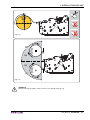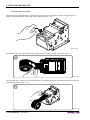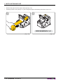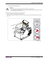
1
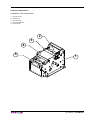
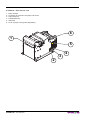
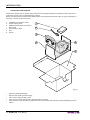
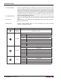
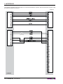
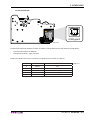
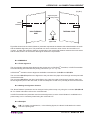
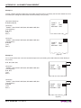
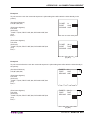
KPM150
USER MANUAL
OEM
TUS
STA
FF
P
PA
AR
NE D
EN
ER
Commands reference: DOMC-0022E
All rights reserved. Total or partial reproduction of this manual in whatever form, whether by printed or
electronic means, is forbidden. While guaranteeing that the information contained in it has been carefully
checked, CUSTOM ENGINEERING SPA and other entities utilized in the realization of this manual bear no
responsibility for how the manual is used.
Information regarding any errors found in it or suggestions on how it could be improved are appreciated.
Since products are subject to continuous check and improvement, CUSTOM ENGINEERING SPA reserves
the right to make changes in information contained in this manual without prior notification.
Copyright © 2010 CUSTOM ENGINEERING S.p.a. – Italy
CUSTOM ENGINEERING SPA
Str. Berettine 2 - 43010 Fontevivo (PARMA) - Italy
Tel.: +39 0521-680111 Fax: +39 0521-610701
http: www.custom.biz
Customer Service Department:
Email: [email protected]
PRINTER COMPONENTS
A. KPM150 - Front external view
1 - Printer frame
2 - Cutter unit
3 - Printer cover
4 - Printing head set
5 - Paper input
2
3
4
5
1
User Manual
KPM150
B. KPM150 – Side external view
1 - Paper outfeed
2 - Connector for external near paper end sensor
3 - LINE FEED key
4 - FORM FEED key
5 - Status led
6 - Lever of paper mouth guide (adjustable)
6
1
TUS
STA
5
FF
AP
RP
ER
A
NE D
EN
4
3
2
KPM150
User Manual
C. KPM150 – External connectors view
1 - USB connector
2 - RS232 connector
3 - Power Supply connector
1
TUS
STA
2
FF
P
PA
AR
NE D
EN
ER
3
User Manual
KPM150
D. KPM150 - Inside view of sensors position
1 - Paper presence sensors on output
2 - Notch sensor
3 - Cover open sensor
4 - Paper out presence
5 - Upper transparence sensor and notch
5
4
3
2
TUS
STA
1
FF
P
PA
AR
NE D
EN
KPM150
User Manual
ER
TABLE OF CONTENTS
INTRODUCTION
MANUAL CONTENTS ...................................................................................................................................... 1
EXPLANATORY NOTES USED IN THIS MANUAL ......................................................................................... 1
GENERAL SAFETY INFORMATION................................................................................................................ 1
UNPACKING THE PRINTER ........................................................................................................................... 2
PRINTER FEATURES ...................................................................................................................................... 3
PRINTER DESCRIPTION ................................................................................................................................ 3
1. INSTALLATION AND USE
1.1 CONNECTIONS ......................................................................................................................................1-1
1.1.1 Power Supply ..................................................................................................................................1-1
1.2 SELF-TEST .............................................................................................................................................1-2
1.3 CONFIGURATION...................................................................................................................................1-3
1.4 HEXADECIMAL DUMP ...........................................................................................................................1-4
1.5 PAPER SPECIFICATIONS ......................................................................................................................1-4
1.5.1 Specifications for ticket with notch ..................................................................................................1-4
1.5.2 Specifications for ticket with gap .....................................................................................................1-6
1.6 MAINTENANCE ......................................................................................................................................1-6
1.6.1 Changing the paper roll ...................................................................................................................1-6
1.6.2 Adjusting paper width ......................................................................................................................1-8
1.6.3 Paper jam ........................................................................................................................................1-9
1.6.4 Cleaning the printing head ............................................................................................................ 1-11
2. INTERFACES
2.1 RS232 SERIAL ........................................................................................................................................2-1
2.2 USB INTERFACE ...............................................................................................................................2-3
3. TECHNICAL SPECIFICATIONS
3.1 TECHNICAL SPECIFICATIONS..............................................................................................................3-1
3.2 DIMENSIONS ..........................................................................................................................................3-2
4. CHARACTER SETS
4.1 CHARACTER SETS IN ESC/POSTM EMULATION .................................................................................4-1
4.2 CHARACTER SETS IN SVELTA EMULATION .......................................................................................4-2
4.3 CHARACTER SETS IN KPM54 EMULATION.........................................................................................4-3
APPENDIX A - ACCESSORIES AND SPARE PARTS
A.1 ACCESSORIES ..................................................................................................................................... A-1
A.1.1 Power Supply ................................................................................................................................. A-1
A.2 SPARE PARTS....................................................................................................................................... A-2
A.3 NOTES FOR TECHNICAL ASSISTANCE.............................................................................................. A-3
A.3.1 Replacing fuse ............................................................................................................................... A-3
APPENDIX B - ALIGNMENT MANAGEMENT
B.1 TICKET ALIGNMENT ............................................................................................................................. B-1
B.1.1 Ticket alignment ............................................................................................................................. B-1
B.1.2 Enabling, calibrating and setting of parameters ............................................................................. B-1
User Manual
KPM150 i
TABLE OF CONTENTS
B.2 COMMANDS .......................................................................................................................................... B-3
B.2.1 Ticket alignment ............................................................................................................................. B-3
B.2.2 Setting the alignment distance ....................................................................................................... B-3
B.2.3 Examples ....................................................................................................................................... B-3
B.3 MECHANICAL CHARACTERISTICS OF THE PRINTER ...................................................................... B-6
B.3.1 Position of the notch ...................................................................................................................... B-6
B.3.2 Dimension of tickets ....................................................................................................................... B-7
B.4 METHODS OF USAGE.......................................................................................................................... B-8
B.4.1 Command sequences .................................................................................................................... B-8
B.4.1.1 Alignment at the cut .................................................................................................................... B-8
B.4.1.2 Alignment at printing ................................................................................................................... B-8
B.4.1.3 Combined alignment ................................................................................................................... B-8
ii KPM150
User Manual
INTRODUCTION
MANUAL CONTENTS
In addition to the Introduction which includes a description of the explanatory notes used in the manual, general
safety information, how to unpack the printer and a brief description of the printer including its basic features,
this manual is organized as follows:
Chapter 1:
Contains the information required for correct printer installation and its proper use
Chapter 2:
Contains information on interface specifications
Chapter 3:
Contains technical specifications of the printer
Chapter 4:
Contains the character sets (fonts) used by the printer
EXPLANATORY NOTES USED IN THIS MANUAL
N.B.
Gives important information or suggestions relative to the use of the printer.
WARNING
Information marked with this symbol must be carefully followed to guard against damaging the
printer.
DANGER
Information marked with this symbol must be carefully followed to guard against operator injury
or damage.
GENERAL SAFETY INFORMATION
•
•
•
•
•
•
•
•
•
•
•
•
•
•
•
Read and keep the instructions which follow.
Follow all warnings and instructions indicated on the printer.
Before cleaning the printer, disconnect the power supply.
Clean the printer with a damp cloth. Do not use liquid or spray products.
Do not operate the printer near water.
Do not use the printer on unstable surfaces that might cause it to fall and be seriously damaged.
During the integration of the printer, we strongly warn to keep an adeguate paper loop outlet underneath
the presenter, in order to allow the receipt being properly printed out.
Only use the printer on hard surfaces and in environments that guarantee proper ventilation.
Make sure the printer is placed in such a way as to avoid damage to its wiring.
Use the type of electrical power supply indicated on the printer label. If in doubt, contact your retailer.
Do not block the ventilation openings.
Do not introduce foreign objects of any kind into the printer as this could cause a short circuit or damage
parts that could jeopardize printer functioning.
Do not spill liquids onto the printer.
Do not carry out technical operations on the printer, with the exception of the scheduled maintenance procedures specifically indicated in the user manual.
Disconnect the printer from the electricity supply and have it repaired by a specialized technician when:
A.
The feed connector has been damaged.
B.
Liquid has seeped inside the printer.
C.
The printer has been exposed to rain or water.
D.
The printer is not functioning normally despite the fact that all instructions in the users ma
nual have been followed.
E.
The printer has been dropped and its outer casing damaged.
F.
Printer performance is poor.
G.
The printer is not functioning.
User Manual
KPM150 1
INTRODUCTION
UNPACKING THE PRINTER
Remove the printer from its carton being careful not to damage the packing material so that it may be reused if the printer is to be transported in the future.
Make sure that all the components illustrated below are present and that there are no signs of damage. If
there are, contact Customer Service.
1. Installation instructions sheet
2. Power supply cable
3. Additional near paper end sensor
with wiring
4. Foam packing shell
5. Box
6. Printer
1
2
3
4
6
5
(Fig.1)
•
•
•
•
•
Open the printer packaging
Remove the cable of power supply
Take out the foam packing shell.
Take out the printer and remove it from its plastic covering.
Keep the box, trays and packing materials in the event the printer must be transported/shipped in the
future.
2 KPM150
User Manual
INTRODUCTION
PRINTER FEATURES
KPM150 is a sturdy and compact printer, extremely strong, suitable for printing tickets in parkings and transports. The printer manages both paper roll and fan-fold. The printer offers a wide range of options in addition to normal print features:
•
•
•
•
•
•
•
•
•
•
•
•
Ticket width: from 20 to 54mm setting from printer setup, with paper thickness from 80 to 180 gr/m2.
Resolution 204 dpi / enhanced quality head
Interfaces : Serial RS232, USB, ETHERNET (optional).
ESC/POS™ emulation, SVELTA emulation.
Character set fonts (ESC/POS™ emulation: 3 standard and international; SVELTA emulation: 20 fonts).
Double width/height, quadruple width/height, expanded, italic, rotated 90°, 180° and 270°.
Internal programmable counter.
Graphic print mode.
Print density (from -50% to +50%).
Sensors: Black mark sensor available in 2 position and translucent gap, ticket sensorWorking with paper roll or Fanfold module
Paper cutter (self-threading cutter and tear off).
PRINTER DESCRIPTION
The printer is comprised of a metal frame, printing mechanism and a cutter. Located on the keypad (see
fig.2) are the following keys: LINE FEED (1), FORM FEED (2) and STATUS led (5).
TUS
STA
3
FF
P
PA
AR
NE D
EN
ER
2
1
(Fig.2)
User Manual
KPM150 3
INTRODUCTION
• LF LINE FEED key
• FF FORM FEED key
• LF + FF key
• STATUS LED
When the LINE FEED key is pressed, the printer advances the paper so that it
may be inserted manually in the printing mechanism. During power-up, if the LINE
FEED key is held down, the printer enters the print setup routine. Following the
print-out of the setup report, the printer remains in standby until a key is pressed
or signals arrive from the serial port; each 7 characters it prints out hexadecimal
and ASCII codes (if the characters are underlined, the receive buffer is full); see
Receive buffer hexidecimal print-out.
When the FORM FEED key is pressed, the printer execute the form feed. During
power-up, if the FORM FEED key is held down, the printer executes the FONT
TEST.
When both the LINE FEED and the FORM FEED keys are pressed the printer
performs a demo ticket.
Displays printer hardware status. In case of malfunction, the colour and flash
frequency changing as follows:.
STATUS LED
COLOR
DESCRIPTION
GREEN
Printer ON : no error
Communication status
GREEN
Nr. flashings
Description
1
Receive data
2
Reception errors (parity, frame error, overrun error)
3
Command not recognized
4
Command reception time out
Recovering error
Nr. flashings
Description
5
Near paper end
Recovering error
YELLOW
Nr. flashings
Description
2
Heading over temperature
3
Paper end
4
Paper jam
5
Power supply voltage incorrect
6
Cover open
Unrecovering error
RED
Nr. flashings
Description
3
Cutter error
4
RAM error
5
EEPROM error
(Tab.1)
4 KPM150
User Manual
1. INSTALLATION AND USE
1.1 CONNECTIONS
1.1.1 Power Supply
(Fig.1.1)
2
1
The printer is equipped with an external power supply outlet (see fig.1.1). The connector pin configuration is
as follows :
Model no. type:
Header :
Housing:
90° Molex series 5569 (no. 39-30-1020)
Molex series 5557 (no. 39-01-3022)
PIN
SIGNAL
1
+24V
2
+GND
(Tab.1.1)
WARNING:
Respect power supply polarity.
This picture 1.2 shows the power supply cable included in the printer packaging :
(Fig.1.2)
MOLEX FEMALE
CONNECTOR 2 PIN
OPPOSITE VIEW SIDE
OF CABLE INSERTION
The connector pin configuration of this cable is as follows:
Female connector
Cable color
Pin 1
RED
Pin 2
BLACK
NOTE: The red cable is for +24 Vdc.
The black cable is for signal ground.
User Manual
KPM150 1-1
1. INSTALLATION AND USE
1.2 SELF-TEST
During power-up, if the LF LINE FEED key is held down, the printer enters the autotest routine and prints out
the Setup report (see fig.1.3). The printer will remain in standby in Hexadecimal dump mode (see par.1.4)
until another key is pressed or characters are received through the printer communication port.
Printer operating status is indicated in the configuration print-out in which, next to the name of the components displayed (see figure 1.3), the following information is given:
• under HEAD VOLTAGE is given the voltage of the head.
• Under HEAD TEMPERATURE is given the temperature of the head.
• Under CUT COUNTER is given the number of cuts made.
• Under POWER ON COUNTER is given the number of power-ups made.
• Under PAPER PRINTED is given the number of centimetres of paper printed.
PRINTER SETTINGS
PRINTER TYPE .............................KPM150
HEAD VOLTAGE
[ V] = 24.29
HEAD TEMPERATURE [°C] = 30
CUT COUNTER
= 5507
POWER ON COUNTER
= 1843
PAPER PRINTED
[cm] = 2635130
Printer Emulation .......................:
Baud Rate ................................:
Data Length ..............................:
Parity ........................................:
Handshaking ............................:
Busy Condition .........................:
USB Address Number (1) ............:
Print Mode .................................:
Height Mode (2)...........................:
Width Mode (2) ............................:
Justification (2) ............................:
Character set (2) .........................:
Panel Buttons (2).........................:
Paperend Sensor (2) ...................:
Autofeed (3).................................:
Chars / inch (3) ............................:
Speed / Quality..........................:
Paper Width...............................:
Paper Threshold ........................:
Notch Position ...........................:
Notch Threshold (4).....................:
Notch Distance [mm] (4)..............:
Print Density..............................:
ESC/POS
115200 bps
8 bits/chr
None
Hardware
RxFull
7
Normal
x1
x1
Left
U.S.A.
Enabled
Enabled
CR disabled
A=15 B=20 cpi
Normal
82 mm
60%
Down Mobile
1.25V
+19.9
0%
[LF] enter Printer Setup
[FF] skip Setup
(Fig.1.3)
1-2 KPM150
User Manual
1. INSTALLATION AND USE
NOTE:
(1)
: This parameter is used to identify univocally the USB printer by a numerical address code, if on the PC are connected
two printers that are the same models for example two USB printers.
(2)
: This parameter is displayed if the printer emulation is set to KPM54.
(3)
: This parameter is displayed if the printer emulation is set to ESC/POSTM.
(4)
: If the “Notch Position” parameter is set to “Disabled” this parameter doesn’t appear in the “Printer Setup”.
1.3 CONFIGURATION
This printer permits the configuration of default parameters. The printer’s configurable parameters are:
•
•
•
•
•
•
•
•
•
•
•
•
•
•
•
•
•
•
•
•
•
•
•
•
•
•
•
Printer Emulation: ESC/POSD , SVELTA, KPM54.
Baud Rate : 115200D, 57600, 38400, 19200, 9600, 4800, 2400, 1200.
Data length : 7, 8D bits/car.
Parity : NoneD, even, odd.
Handshaking : XON/XOFF, HardwareD.
Busy condition : RXFullD , OffLine/RXFull.
USB Address Number : 0D, 1, 2, 3, 4, 5, 6, 7, 8, 9.
Print mode: NormalD or Reverse.
Height Mode (2): x 1D, x 2, x 4.
Width Mode (2): x 1D, x 2, x 4.
Justification (2): LeftD, Centered or Right.
Character set (2): U.S.A.D, Standard Europe.
Panel Buttons (2): EnabledD, Disabled.
Paperend Sensor: Enabled, DisabledD.
Autofeed: CR disabledD , CR enabled.
Chars/Inch: A=11 B=15 cpi, A=15 B=20 cpiD.
Speed/Quality : Normal, High SpeedD.
Paper width : 20mm, 22mm, 24mm, 26mm, 28mm, 30mm, 32mm, 34mm, 36mm, 38mm, 40mm, 42mm,
44mm, 46mm, 48mm, 50mm, 52mm, 54mmD.
Paper Threshold(5) : 30%, 40%, 50%, 60%D, 70%, 80%, 90%.
Notch Position(6) : DisabledD, Down Mobile, Tr. Side, Up Side.
Notch Threshold(7): 30%, 40%D, 50%, 60%, 70%, 80%, 90%.
Notch Distance Sign(4) : +D , Notch Distance [mm x 100](4)(8): 0D, 1, 2, 3, 4, 5, 6, 7, 8, 9.
Notch Distance [mm x 10](4)(8): 0D, 1, 2, 3, 4, 5, 6, 7, 8, 9.
Notch Distance [mm x 1](4)(8): 0D, 1, 2, 3, 4, 5, 6, 7, 8, 9.
Notch Distance [mm x .1](4)(8): 0D, 1, 2, 3, 4, 5, 6, 7, 8, 9.
Print Density: -50%, -37%, -25%, -12%, 0D,+12%, +25%, +37%, +50%.
General notes:
The parameters marked with the symbol D are the default values.
Settings remain active even after the printer has been turned off.
NOTE:
: This parameter indicates the threshold value under the sensor detect the paper.
(6)
: This parameter sets which sensor is used as notch sensor. There are two sensor operating mode: reflection or transparence.
(7)
: This parameter is used to detect the presence of the notch. In order to better identify the optimum threshold for the
paper being used, a paper characterization function is also available in the setup.
(8)
: The “Notch distance” parameter represents the distance in mm from the upper margin of the ticket to the black mark
on the ticket. For example, to set notch distance to 15 mm, modify the following parameters in order to obtain the desired
values as indicated :
(5)
Notch Dist. [mm x 100] : 0
Notch Dist. [mm x 10]
:1
Notch Dist. [mm x 1]
:5
Notch Dist. [mm x .1]
:0
The settings made are stored in EEPROM (nonvolatile memory).
User Manual
KPM150 1-3
1. INSTALLATION AND USE
During the setup routine the printer prints out the setup report (see fig. 1.3), pressing the LINE FEED key
to enter the Setup mode. To modify printer’s parameters follow the instructions printed on the paper for the
FORM FEED key and LINE FEED key functionality.
1.4 HEXADECIMAL DUMP
This function is used to diagnose the characters received through the communication port; the characters are
printed out both as hexadecimal codes and ASCII codes.
Once the self-test routine has finished, the printer enters Hexadecimal Dump mode. The printer remains in
standby until a key is pressed or characters are received through the communication port.
For every 7 characters received, the hexadecimal and corresponding ASCII codes are printed out (if the
characters are underlined, the receive buffer is full). Shown below is an example of a Hexadecimal Dump:
48
65
78
61
64
65
63
Hexadec
69
6D
61
6C
20
64
75
imal
6D
70
20
66
75
6E
63
mp func
74
69
6F
6E
20
30
31
tion
32
33
34
35
36
37
38
2345678
61
62
63
64
65
66
67
abcdefg
68
69
6C
6D
6E
6F
70
hilmnop
71
72
73
74
75
76
77
qrstuvw
du
01
1.5 PAPER SPECIFICATIONS
The printer prints on ticket width from 20 to 54 mm adjustable by the user; this printer manages both paper
roll, fan-fold and ticket with notch. Place the notch on the heat sensitive side or on the non-heat sensitive
side of the ticket.
The following paragraphs give the specifications and dimensions for each ticketconfi guration.
1.5.1 Specifications for ticket with notch
Printer is provided with 2 sensors for the notch detection as shown in fig.1.4, where :
• 1 = mobile notch sensor
• 2 = fixed notch/transparence sensor.
2
1
S
U
STAT
FF
R PA
N EAD
EN
P ER
(Fig.1.4)
1-4 KPM150
User Manual
1. INSTALLATION AND USE
WARNING:
In the regulation of mobile sensor it’s
very important to not use too much
force in moving the sensor inside its sliding guide and not use a tool that could
damage the sensor to avoid breaking
(see fig.1.5). Adjust the sensor using a
screwdriver or a pencil.
(Fig.1.5)
Paper with alignment notches may be used; referred to Appendix B on this manual to see the ticket specifications and management of notch alignment. Fig. 1.6 shows an example of paper roll with notch on the heat
sensitive side (printable side), where:
L
= represents the paper width used ( 20 ÷ 54 mm);
Ticket axis
14
7
5
Sensor axis
Notch
Thermal
Side
Direction
of paper feed
L
(Fig.1.6)
NOTE: If the notch was on the heat sensitive side, the image on the paper (fig.1.6) would be mirrored in regard to the paper axis.
User Manual
KPM150 1-5
1. INSTALLATION AND USE
1.5.2 Specifications for ticket with gap
The printer manages tickets with lateral gap. Set the “Notch position” parameter (see printer setup) with
“Transparent side” value for print and cut the ticket. Fig.1.7 shows an example for ticket with lateral gap.
Sensor axis
Side gap
3
7
3
Ticket margin
(Fig.1.7)
where
L
= represents the paper width used (20 ÷ 54mm);
H
= indicates the managed minimum height (2mm)
D
= indicates the minimum width (10mm)
1.6 MAINTENANCE
1.6.1 Changing the paper roll
To change the paper roll proceed as follows:
1. Position the paper roll so that it unrolls in the direction shown in fig.1.8.
2. Insert the paper into the paper infeed opening and wait for it to load automatically (see fig.1.9).
Fig.1.9 gives alignment specifications for correct paper loading.
1-6 KPM150
User Manual
1. INSTALLATION AND USE
(Fig.1.8)
90°
OK
OK
90°
(Fig.1.9)
WARNING
Before inserting the paper, make sure the cut is straight (see fig.1.8).
User Manual
KPM150 1-7
1. INSTALLATION AND USE
1.6.2 Adjusting paper width
Paper width may be adjusted from a minimum value of 20mm to a maximum of 54mm using the lever of
paper mouth guide located at the paper infeed opening (see fig.1.10).
(Fig.1.10)
Position the paper roll in the loading paper guide, so that it unrolls correctly, as shown in fig.1.11.
1
(Fig.1.11)
Press the the lever of paper mouth guide and move it to regulate the width of the paper guide in according to
type of paper used, see fig.1.12.
2
(Fig.1.12)
1-8 KPM150
User Manual
1. INSTALLATION AND USE
1.6.3 Paper jam
When occurs a paper jam the “status LED” signals the corresponding printer status as follows:
STATUS
LED
S
U
STAT
COLOUR
FLASHING
NUMBER
DESCRIPTION
YELLOW
4
PAPER JAM
FF
R PA
N EAD
EN
P ER
(Fig.1.13)
In case of paper jam proceed as follows:
• Open the printer cover (see fig.1.14).
2
1
(Fig.1.14)
•
(Fig.1.15)
Check that there are no scraps of paper in the printer. If there are, remove the scraps before proceeding
with any other operation. DO NOT insert any kind of object inside the cutter.
User Manual
KPM150 1-9
1. INSTALLATION AND USE
•
•
Remove the paper from the paper infeed (see fig.1.16).
Close the printer cover (see fig.1.17) and change the paper roll following instructions of par.1.6.1.
4
3
SEE PARAGRAPH 1.6.1
(Fig.1.16)
1-10 KPM150
User Manual
(Fig.1.17)
1. INSTALLATION AND USE
1.6.4 Cleaning the printing head
WARNING:
• Do not touch the head heating line with bare hands or metal objects.
• Do not perform any operation inside the printer immediately after printing because the head
and motor tend to become very hot.
First disconnect the power supply and proceed as follows:
• Open the printer cover (see previous paragraphs).
• Clean the printing head heating line using a non-abrasive cloth moistened with isopropyl alcohol (see
fig.1.18).
Isopropyl
alcohol
TUS
STA
FF
AP
RP
ER
A
NE D
EN
(Fig.1.18)
User Manual
KPM150 1-11
1. INSTALLATION AND USE
Blank page
1-12 KPM150
User Manual
2. INTERFACES
2.1 RS232 SERIAL
The printer has an RS232 serial interface and is connected by means of a 9 pin female connector (see fig.
2.1).
1
5
6
RS232
9
(Fig.2.1)
In the following table, the signals present on the connector are listed:
(Tab.2.1)
PIN
SIGNAL
IN/OUT DESCRIPTION
1
DCD
OUT
2
TXD
OUT
3
RXD
IN
4
N.C.
-
Not connected.
5
GND
-
Ground signal.
6
DSR
OUT
7
N.C.
-
8
RTS
OUT
9
N.C.
-
Data Carrier detect. Printer ON (active at level RS232 high).
Receive data. Serial output (from Host).
Transmit data. Serial data input (towards Host).
Data Set Ready. Printer on and operating (active at RS232 level high).
Not connected.
Clear to send. Ready to receive data (active at RS232 high level).
Not connected
User Manual
KPM150 2-1
2. INTERFACES
The following diagrams show examples of connections between the printer and the Personal Computer using
25 and 9 pin female connectors.
(Fig.2.2)
PRINTER
PC
PRINTER
PC
2-2 KPM150
User Manual
2. INTERFACES
2.2 USB INTERFACE
4
3
1
2
USB type B
(Fig.2.2)
Printers with USB serial interface conform to USB 2.0 Full Speed and have the following specifications:
•
•
Communication speed 12 Mbit/sec
“Receptacle series B” - type connector.
Refer to the table below for the connector pin signals and connection to a device:
PIN
SIGNAL
DESCRIPTION
1
VBUS
N.C.
2
D-
Data -
3
D+
Data +
4
GND
Ground signal
Shell
Shield
Cable shield
User Manual
(Tab.2.2)
KPM150 2-3
3. TECHNICAL SPECIFICATIONS
3.1 TECHNICAL SPECIFICATIONS
Table 3.1 gives the main technical specifications for the printer model.
(Tab.3.1)
Standard interfaces
Communication speed
USB 2.0 Full Speed
RS232
12 Mbit/sec
from 1200 to 115200 bps
Resolution
204 DPI (8 dot/mm)
Paper specifications
Thermal rolls Heat-sensitive side on outside of roll
Fan Fold thermal paper with notch
Type of paper
Paper width
from 20mm to 54mm (step di 2mm)
Recommended types of
paper
from 80 g/m2 to 180 g/m2
max Ø180 mm (1)
External roll diameter
Internal roll core diameter
min 50 mm (+1 mm)
Core thickness
2 mm (+1 mm)
Paper end
Not attached to roll core
Core type
Cardboard or plastic
Sensors
Ticket presence, head temperature, black mark detector in 3 positions and
translucent gap/hole mark detector (setting by software),
ticket presence on output, cover open, external near paper end.
Printing method
Thermal, fixed head (8 dot/mm)
Printing mode
Printing format
Normal, 90°, 180°, 270°
Height/Width from 1 to 8, bold, reverse, underlined, italic
TM
Character fonts
ESC/POS emulation: PC437, PC850, PC860, PC863, PC865, PC858, PC866
SVELTA emulation:
20 embedded fonts
KPM54 emulation:
PC437
Receive buffer
2 Kbytes
Flash memory
1 Mbytes + 128 Kbytes
Graphic memory
Printing speed
Head life
MCBF
MTBF
Logos dynamic management (max 32KB graphics memory)
Normal
High speed
120 mm/sec
160 mm/sec
50 Km / 100M pulses
1 000 000 cutter number
(2)
400 000 hours
Mechanical Characteristics
Dimensions
Weight [gr.]
Length [mm] =
Height [mm] =
Width [mm] =
171
122 (with cover closed)
114
1850 (without paper roll)
Electrical input
Power supply
Average
(8)
Stand-by
24 Vdc ± 10%
0.7 A
70 mA
User Manual
KPM150 3-1
3. TECHNICAL SPECIFICATIONS
Environmental conditions
Operating temperature
Relative humidity
Storage temperature / Humidity
Emulation
EMULATION ESC/POSTM
Character density
Number of columns
Chars / sec
Lines / sec
0°C - 50°C
10% - 85% w/o condensation
-20°C - +70°C / 10% - 90%
ESC/POSTM, SVELTA, KPM54
Characters (L x H mm)
Normal
Character set
EMULATION KPM54
Character density
Number of columns
Chars / sec
Lines / sec
Characters (L x H mm)
Normal
Character set
NOTE:
(1)
11 cpi
35
2900
83
15 cpi
45
3800
83
20 cpi
64
5300
83
2,25x3
1,75 x 3
3
1,25 x 3
11 cpi
27
351
13
15 cpi
38
494
13
2,25x3
1,75 x 3
2
For external rolls diameter higher to Ø100mm it’s recommended to use a paper
pretensioning device.
Electronic board.
Referred to a standard CUSTOM receipt (L=10cm, Density = 12,5% dots on).
(2)
(3)
3.2 DIMENSIONS
In the following figure shows the dimensions of the printer.
86
119
84
105
122
99,5
88
171
175,5
114
140
120
102
13
(Fig.3.1)
3,7
3-2 KPM150
7
Ø
Ø
User Manual
4. CHARACTER SETS
4.1 CHARACTER SETS IN ESC/POSTM EMULATION
The printer has 3 embedded fonts of varying width (11, 15 and 20 cpi) which may be accessed through
programming (section 1.3) or control characters (see Command Reference). Each of these fonts offers the
following code tables: PC437, PC850, PC860, PC863, PC865, PC858, PC866.
Shown below in figure 4.1 are examples of the 11 cpi character set.
PC863
(CanadianFrench)
PC437
(Usa,Standard,
Europe)
PC865
(Nordic)
PC850
(Multilingual)
PC858
(Euro symbol)
PC860
(Portuguese)
PC866
(Cyrillic)
(Fig.4.1)
To print the Euro (€) symbol, the command sequence is: $1B, $74, $13, $D5.
User Manual
KPM150 4-1
4. CHARACTER SETS
4.2 CHARACTER SETS IN SVELTA EMULATION
In SVELTA emulation the printer has 20 embedded fonts of varying width which may be accessed through
control characters (see commands description in SVELTA emulation of Command Reference). The following
list shows the font availables and relative dimensions in dot:
•
•
•
•
•
•
•
•
•
•
•
•
•
•
•
•
•
•
•
Font HEL8PT8 (A)
Font HEL10PT8 (A)
Font HEL14PT8 (A)
Font HEL16PT8 (A)
Font 18x24
Font 14x24
Font 10x24
Font 8x12 (B)
Font 8x12-2 (B)
Font 12x12 (B)
Font 14x11 (B)
Font 16x24 (B)
Font 16x24_1 (B) (C)
Font 16x24_2 (B) (C)
Font 20x15 (B)
Font 28x20 (B)
Font 14x24_1 (B) (C)
Font 16x24CN (B) (C)
Font OCRB (20x32) (B)
Proportional Font with fixed height (H = 28 dot)
Proportional Font with fixed height (H = 34 dot)
Proportional Font with fixed height (H = 50 dot)
Proportional Font with fixed height (H = 55 dot)
(Font 18x24 in ESC/POS emulation)
(Font 14x24 in ESC/POS emulation)
(Font 10x24 in ESC/POS emulation)
Fixed Font
Fixed Font
Fixed Font
Fixed Font
Fixed Font
Fixed Font
Fixed Font
Fixed Font
Fixed Font
Fixed Font
Fixed Font
Fixed Font
For further informations to characters representations print directly the Font Test(D).
NOTE:
(A)
(B)
(C)
(D)
4-2 KPM150
A proportional font is a font in which different characters have different pitches
(widths).
A fixed font is the opposite of a proportional font and is a fixed-pitch font.
The fonts with the same name and dimension contain different characters in different
positions from theirs.
During power-up, if the FORM FEED (FF) key is held down, the printer executes the
FONT TEST.
User Manual
4. CHARACTER SETS
4.3 CHARACTER SETS IN KPM54 EMULATION
The printer has 2 embedded fonts of varying width (11 and 15 cpi) which may be accessed through programming (section 1.3) or control characters (see Command Reference). Each of these fonts offers the
following code table: PC437.
Shown below in figure 4.2 are examples of the 11 cpi character set.
PC437
(Usa, Standard, Europe)
(Fig.4.2)
To print the Euro (€) symbol, the command sequence is: $1B, $74, $13, $D5.
User Manual
KPM150 4-3
4. CHARACTER SETS
Blank page
4-4 KPM150
User Manual
APPENDIX A - ACCESSORIES AND SPARE PARTS
A.1 ACCESSORIES
A.1.1 Power Supply
The figure below illustrates the power supply provided by Custom to be used for printer operation.
Dimensions in mm:
(Fig.A.1)
5
3
193.0
5
3
CN1
6.5
L
N
FG
95.0
95.0
-V
-V
+V
9.0
+V
5.5
4.5
4 - M3 - P 0.5
120.0
62.0
198.0
6.5
20.0
158.0
13.5
RANGE
7.0
10.0
18.0
3.5
3 - M3 - P 0.5
10
38
9.5 9.0
3.4 HOLE
<8
8 25
25 80
80 250
250 800
800 2600
ANGULAR
TOLERANCE
B
0.1
0.15
0.25
0.4
0.8
1.5
0.3°
(Tab.A.1)
PPSPS-100-24V
Input specification
Output specification
Environmental condition
Switching power supply 24V 100W
Input voltage
85V ÷ 264V
Current
0A ÷ 4.5A
Input frequency
47Hz ÷ 63Hz
Output voltage
24V
Output current
0A ÷ 4,5A
Efficiency
80%
Operating temperature
0°C ÷ 70°C
Humidity
20% ÷ 85% Rh (w/o condensation)
Storage temperature / Humidity
-10°C ÷ 75°C/
10% ÷ 95% (w/o condensation)
Protection devices: Shortcircuit, overload and overvoltage.
User Manual
KPM150 A-1
APPENDIX A - ACCESSORIES AND SPARE PARTS
A.2 SPARE PARTS
COMPONENT
Thermal paper roll 54mm
(Øext= 300mm, Øint= 76mm, 140gr)
A-2 KPM150
User Manual
CODE
RCT54X300-76MM-140GR
APPENDIX A - ACCESSORIES AND SPARE PARTS
A.3 NOTES FOR TECHNICAL ASSISTANCE
ATTENTION: The operations here described are exclusively aimed to the personnel handling
the technical assistance of the printer.
ATTENTION: Disconnect the power supply during maintenance operations.
A.3.1 Replacing fuse
ATTENTION: Before replacing the fuse, it’s important to check up that the supply cable of the
printer is out.
The fuse is on the control board of the printer, near the supply connector proceed as follows :
• Disconnect the power supply connector and all communication cables.
• Unscrew the three fixing screws for the back closing and then remove as shown in fig. A. 2.
• Unscrew the four screws that fixing control board to the chassis as shown in fig. A.3.
1
2
STAT
US
STAT
US
LF
NE
ENDAR PAPE
R
FF
LF
NE
ENDAR PAPE
R
(Fig.A.2)
•
FF
(Fig.A.3)
Disconnect from the control board the cables paying attention to the different cables plugged in the connectors:
User Manual
KPM150 A-3
APPENDIX A - ACCESSORIES AND SPARE PARTS
•
•
Unlock the control board position pushing in the direction indicated by the arrow as shown in fig. A.4.
Extract the control board from its seating in the direction indicated by the arrow as shown in fig. A.5.
3
4
STAT
US
STAT
US
LF
LF
NE
ENDAR PAPE
R
NE
ENDAR PAPE
R
FF
(Fig.A.4)
•
•
•
FF
(Fig.A.5)
The fuse is on the control board of the printer, near the supply connector (fig A.6). Unsolder the fuse at his
end, paying attention to not heat excessively the closed components, to not take any risk to damage it.
Replace the fuse with a new one with same specifications (5A, 60Vdc) and place it again in its seating.
Reassemble the control board on the printer using these instructions in reverse order.
5
(Fig.A.6)
A-4 KPM150
User Manual
APPENDIX A - ACCESSORIES AND SPARE PARTS
Blank page
User Manual
KPM150 A-5
APPENDIX B - ALIGNMENT MANAGEMENT
B.1 TICKET ALIGNMENT
B.1.1 Ticket alignment
Paper with an alignment notch can be used in order to handle tickets with pre-printed fields and a fixed
length.
To guarantee the alignment it is necessary that the “Notch Alignment” parameter is enabled from the key
setup (see setting configuration parameters), that the alignment sensor is calibrated and that the parameters
are set.The calibration of the sensor occurs automatically within the printer setup.
B.1.2 Enabling, calibrating and setting of parameters
The printer manages tickets with notch; place the notch on the heat sensitive side or on the non-heat sensitive side of the ticket (see par. 1.5 Paper Specifications).
To guarantee a correct alignment it is necessary that the “Notch Position” parameter is setted with the right
value because the printer must know which sensor utilize from notch searching.
All printer sensors are reflection sensors: this kind of sensor emits a band of light and detects the quantity of
light reflected to it.
The presence of the notch is therefore detected by the amount of light that returns to the sensor, taking into
account that the light is reflected by the white paper and absorbed by the black mark.
However is possible to use transparence sensors, using the sensor’s transmitter with the receiver of the opposite: during this operating condition a beam of light is emitted by a sensor and the quantity of light which
reaches the opposite receiver is detected, therefore for this reason the sensor less mobile be moved around
to the left so that it is perfectly aligned with the upper.
The presence of the notch so is detected evaluating the amount of light that arrives to the opposite sensor,
considering that the paper doesn’t allow the beam of light to reach the receiver, whereas a gap (like label
with gap ) or hole, lets the light to reach the receiver.
“Notch Position”
parameter
Using mode
Notch position on
ticket
Notes
Disabled
N.A.
N.A.
Alignment disabled
Down mobile
REFLECTION
Lateral non-thermal side
Using notch printed on ticket to align
Up side
REFLECTION
Lateral thermal side
Using notch printed on ticket to align
Tr. side
TRANSPARENCE
Lateral
Using ticket with gap or label with gap
Calibration of the sensor occurs automatically and consists in adjusting the quantity of light emitted to adapt
it to the degree of whiteness of the paper used.
To start self-calibration, the “Notch Position ” parameter will be setted in a different value by “Disabled” value
from the printer setup (see setting configuration parameters).
The printer will perform some paper FEEDS, at the end of which it will print the calibraration result and the
value of the PWM duty-cycle of the alignment sensor driver so that it can be perform an optimal notch detection, for example:
Autosetting Notch
PWM Duty Cycle
: OK
: 85.3%
When use the trasparence sensor the value of the “PWM Duty Cycle”
is managed with a fixed value
The “Autosetting Notch” parameter indicates the operating condition of the self-calibration process; OK will
appear if it has been successful, but if it has failed the words NOT OK will appear.
User Manual
KPM150 B-1
APPENDIX B - ALIGNMENT MANAGEMENT
Another parameter that needs to be set is the threshold:
Notch Threshold..
: 40%
It is used to detect the presence of the notch: if the voltage value read by the sensor exceeds the threshold
value set the notch is identified, otherwise the white paper is considered.
In order to better identify the optimum threshold for the paper being used, a paper characterisation function is
also available in setup.
Characterize Paper.
:Yes
By activating this parameter the outgoing voltage of the sensor will be presented in a graphic form as shown
in figure B.1 below:
PAPER CHARACTERIZATION
(Fig.B.1)
Notch Threshold
The graphic shows the outgoing voltage of the sensor and the threshold value previously set. It is clear that
by adjusting the threshold value it is possible to find the best position that takes into account the signal peak
and the small oscillations around zero.
The ALIGNMENT POINT is defined as the position inside the ticket that is the desired alignment point.
The ALIGNMENT POINT can be defined over the notch or near this one; for this reason, the final parameters to be set in setup are:
Notch Dist. [mm x 100] : 0
Notch Dist. [mm x 10] . : 1
Notch Dist. [mm x 1] . : 5
Notch Dist. [mm x .1] . : 0
These parameters define the “Nocth Distance” that represents the distance from the notch to align or simply
identify the notch distance from the ticket margin; in the above example the notch distance is 15 mm.
B-2 KPM150
User Manual
APPENDIX B - ALIGNMENT MANAGEMENT
(Fig.B.2)
Alignment point
(ticket start position)
Notch
Distance
NON-THERMAL
SIDE
THERMAL SIDE
Direction of
paper feed
Figure B2 shows how the “Notch Distance” parameter represents the distance that exists between the notch
and the desired alignment point. This parameter can have a minimum value of 0mm and a maximum of
19,9mm. In reality the maximum distance corresponds to the mechanical distance between the notch sensor
and the head, and it is for this reason that higher values are not permitted.
B.2 COMMANDS
B.2.1 Ticket alignment
The commands to manage ticket alignment are present only in ESC/POSTM emulation; in SVELTA emulation
are automatically performed with the printing commands <p> <P> <q> <Q>.
In ESC/POSTM emulation the two alignment available commands are : $1D $F6 and $1D $F8.
The command $1D $F6 performs an alignment to the print head: the paper is fed through until the print head
is at the ticket start.
The command $1D $F8 on the other hand refers to the cutter: the paper is fed through until the cutter is at
the set alignment point of the next ticket, so that a subsequent cut will occur precisely at the end of the ticket.
B.2.2 Setting the alignment distance
The “Notch Distance” parameter can be changed via the printer setup or by using the command $1D $E7 nH
nL. For further information refer to the command itself.
In SVELTA emulation the parameter used to set the alignment is not the “Notch Distance” modifiable in the
printer setup, but it is necessary setted using the command LHT.
B.2.3 Examples
N.B.: To a better comprehension, in the following figures, the Notch is indicated on the same
side of the printing text.
User Manual
KPM150 B-3
APPENDIX B - ALIGNMENT MANAGEMENT
Example 1
To print a ticket’s sequence witch the cut is made over the notch it’s necessary set the notch distance to zero
as follows (this setting have effect after the ticket already in the printer):
{Set Notch Distance}
$1D,$E7,$00,$00,
{Print text}
‘TICKET 1’,$0A,’FIRST LINE’,$0A,’SECOND LINE’,$0A
{Cut alligment}
$1D, $F8,
{Cut}
ESC,’i’,
...
{Print text}
‘TICKET 1’,$0A,’FIRST LINE’,$0A,’SECOND LINE’,$0A
{Cut alligment}
$1D,$F8,
{Cut}
ESC,’i’,
...
TICKET
N
FIRST
LINE
SECOND LINE
TICKET
(N+1)
FIRST
LINE
SECOND LINE
(Fig.B.3)
Example 2
10
To cut 10mm before the notch the command sequence is (this setting have effect after the ticket already in
the printer):
$1D, $E7, $00, $0A,
{Print text}
‘TICKET 1’,$0A,’FIRST LINE’,$0A,’SECOND LINE’,$0A
{Cut alligment}
$1D,$F8,
{Cut}
ESC,’i’,
...
TICKET
N
FIRST
LINE
SECOND LINE
10
{Print text}
‘TICKET 1’,$0A,’FIRST LINE’,$0A,’SECOND LINE’,$0A
{Cut alligment}
$1D, $F8,
{Cut}
ESC,’i’,
...
TICKET
(N+1)
FIRST
LINE
SECOND LINE
(Fig.B.4)
B-4 KPM150
User Manual
APPENDIX B - ALIGNMENT MANAGEMENT
Example 3
To print over the notch the command sequence is (this setting have effect after the ticket already in the
printer):
{Set Notch Distance}
$1D,$E7,$00,$00,
{Print head aligment}
$1D, $F6,
{Print text}
‘TICKET 1’,$0A,’FIRST LINE’,$0A,’SECOND LINE’,$0A
{Cut}
ESC,’i’
...
{Print head aligment}
$1D, $F6,
{Print text}
‘TICKET N’,$0A,’FIRST LINE’,$0A,’SECOND LINE’,$0A
{Cut}
ESC,’i’
TICKET
N
FIRST
LINE
SECOND LINE
TICKET
(N+1)
FIRST
LINE
SECOND LINE
(Fig.B.5)
Example 4
TICKET
N
FIRST
LINE
SECOND LINE
15
{Set Notch Distance}
$1D,$E7,$00,$0F,
TICKET
(N+1)
FIRST
LINE
SECOND LINE
15
To print 15mm before the notch the command sequence is (this setting have effect after the ticket already in
the printer):
{Print head aligment}
$1D, $F6,
{Print text}
‘TICKET 1’,$0A,’FIRST LINE’,$0A,’SECOND LINE’,$0A
{Cut}
ESC,’i’
...
{Print head aligment}
$1D, $F6,
{Print text}
‘TICKET N’,$0A,’FIRST LINE’,$0A,’SECOND LINE’,$0A
{Cut}
ESC,’i’
(Fig.B.6)
User Manual
KPM150 B-5
APPENDIX B - ALIGNMENT MANAGEMENT
B.3 MECHANICAL CHARACTERISTICS OF THE PRINTER
B.3.1 Position of the notch
Figure B.7 shows a section of the printer and the distances between the head, the cutter and the notch sensor.
SENSOR
39,7
PRINT HEAD
CUTTER
26,5
(Fig.B.7)
B-6 KPM150
User Manual
APPENDIX B - ALIGNMENT MANAGEMENT
B.3.2 Dimension of tickets
It is very important to well calibrate the height of the printer area, according to the distance between the two
edges of the notch. In order not to miss a notch (a ticket must therefore contain only one notch) the following
equation must be used:
INTER-NOTCH DISTANCE>PRINTED AREA HEIGHT
where
INTER-NOTCH DISTANCE = the distance between two notch edges
The picture in figure B.8 shows a sequence of printed tickets aligning each one at the cut. It can be noted
that increasing the printed area will result in superimposing what is to be printed at the subsequent notch.
The size of the print area can be enlarged until it renders the alignment feed void, but not beyond.
LEGEND:
A = Alignment feed
H = Printing area height
D = Inter-notch distance
A
H
D
DIRECTION OF
PAPER FEED
(Fig.B.8)
N.B.: In ESC/POSTM emulation to prevent any jamming, after cut, the paper is not completely
recovered, but it remains outside the printing line of 10mm; so it’s very important to consider this
distance, in this emulation, during the ticket layout definition.
In SVELTA emulation, directly designed for ticketing, on the contrary the paper recovering is not
necessary, because after a cut non-printable areas are not produced.
User Manual
KPM150 B-7
APPENDIX B - ALIGNMENT MANAGEMENT
B.4 METHODS OF USAGE
B.4.1 Command sequences
It is possible, when printing sequences of tickets, to primarily identify two different methods of operation that
involve the alignment: ticket aligned at the cut, ticket aligned at printing and combined alignment.
B.4.1.1 Alignment at the cut
The sequence of commands to be entered when wanting to align a ticket at the cut is as follows:
1.
2.
3.
4.
Ticket general setting; formatting of characters, print density, margins etc.
Print ticket: Printing of text, logos or any other graphics.
Alignment at the cut command: $1D $F8.
Cut command.
B.4.1.2 Alignment at printing
Alignment at printing requires the following sequence of commands:
1. Ticket general setting; formatting of characters, print density, margins etc.
2. Print alignment commands: $1D $F6.
3. Print ticket: Printing of text, logos or any other graphics.
4. Cut command.
Unlike the previous case, the alignment feed takes place before the start of printing, so as to align the print
area in the position required.
B.4.1.3 Combined alignment
The combined alignment at printing and at the cut is the most alignment used on ticketing applications and
requires the following sequence of commands:
1. Ticket general setting; formatting of characters, print density, margins etc.
2. Print alignment commands: $1D $F6
3. Print ticket: Printing of text, logos or any other graphics.
4. Alignment at tha cut command.
5. Cut command.
This method of operation has favourable, compared with previously methods, because all printed thickets are
the same length apart from length of printable area.
B-8 KPM150
User Manual
Rev. 1.00
Part Number : DOME-KPM150
CUSTOM ENGINEERING SPA
World Headquarters
Via Berettine, 2 - 43010 Fontevivo, Parma ITALY
Tel. +39 0521 680111 - Fax +39 0521 610701
[email protected] - www.custom.biz
All rigths reserved
www.custom.biz