1
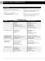
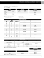
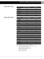
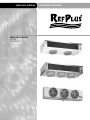
INSTALLATION, OPERATION
WALK-IN COOLERS
SERIES
LS-LP-LA-LV
1
& MAINTENANCE INSTRUCTIONS
INSTALLATION, OPERATION & MAINTENANCE INSTRUCTIONS
CONTENTS
SERVICE . . . . . . . . . . . . . . . . . . . . . . . . 5
INSPECTION . . . . . . . . . . . . . . . . . . . . . . . . 5
CLEANING. . . . . . . . . . . . . . . . . . . . . . . . . 5
SAFETY CONSIDERATIONS . . . . . . . . . . . . . 3
INTRODUCTION . . . . . . . . . . . . . . . . . . . 3
INSTALLATION
STEP 1 – COMPLETE PRE-INSTALLATION CHECKS .
STEP 2 – LOCATION . . . . . . . . . . . . . . . .
STEP 3 – MOUNTING . . . . . . . . . . . . . . . .
STEP 4 – CONNECT DRAIN LINE . . . . . . . . .
STEP 5 – REFRIGERANT CONNECTIONS . . . . . .
STEP 6 – EXPANSION VALVE CONNECTION . . . .
STEP 7 – WIRING . . . . . . . . . . . . . . . . .
START-UP
LEAK TESTING AND EVACUATION . . . . . . . .
FAN MOTOR . . . . . . . . . . . . . . . . . . .
FAN DELAY DEFROST TERMINATION CONTROL .
FAN DELAY DRAIN PAN CONTROL . . . . . . .
CHECK SUPERHEAT . . . . . . . . . . . . . . . .
DEFROST SYSTEM . . . . . . . . . . . . . . . .
.
.
.
.
.
.
.
.
.
.
.
.
.
.
UNIT SPECIFICATIONS . . . . . . . . . . . . . . . 6
3
3
3
3
4
4
4
TROUBLESHOOTING CHART. . . . . . . . . . . . 6
TECHNICAL DATA . . . . . . . . . . . . . . . . . . . . . 7
TECHNICAL DATA (CONT’D) . . . . . . . . . . . . . . . 8
REFRIGERATION SYSTEM
START-UP CHECK LIST . . . . . . . . . . . . . . . . . 10
WARRANTIES . . . . . . . . . . . . . . . . . . . . 11
.
.
.
.
.
.
.
.
.
.
.
.
.
.
.
.
.
.
.
.
.
.
.
.
4
4
4
4
4
5
NOMENCLATURE
L
L = Low
S = Silhouette
P = Profile
A = Air
S
A
224
1
—
1
1 = 120/1/60
2 = 240/1/60
5 = 208-240/3/60
8 = 600/3/60
9 = 480/3/60
Product Generation
A = Air Defrost
E = Electric Defrost
G = Reverse Cycle Hot Gas Defrost
W/Electric Heated Drain Pan
H = Three Pipe Hot Gas Defrost
W/Electric Heated Drain Pan
R = Reverse Cycle Hot Gas Defrost
T = Three Pipe Hot Gas Defrost
2
Unit Capacity @ 10oF T.D. 22,400 Btu/hr
INSTALLATION, OPERATION & MAINTENANCE INSTRUCTIONS
SAFETY CONSIDERATIONS
INSTALLATION
Installing, starting up, and servicing equipment can
be hazardous due to system pressures, electrical
components and equipment location (roofs, elevated
structures, etc.). Only trained, qualified installers and
service mechanics should install, start up, and service
this equipment.
STEP 1 COMPLETE PRE-INSTALLATION CHECKS
Examine for damage incurred during shipment.
File a claim immediately with transit company if
damage is found. Verify that the nameplate electrical
requirements match the available power supply.
Check the shipment for completeness.
When working on the equipment, observe precautions
in the literature and on the tags, stickers, and labels
attached to the equipment.
Follow all safety codes. Wear safety glasses and work
gloves. Keep quenching cloths and fire extinguisher
nearby when brazing. Use care in handling, rigging,
and setting bulky equipment.
WARNING
Before installation, always check to be sure main
power to systems is OFF. Electrical shock can
cause personal injury or death.
STEP 2 - LOCATION
All unit coolers should be installed flush against the
ceiling. The unit cooler must be level in all directions
to ensure proper drainage of condensate. Be sure
there is sufficient clearance between the ceiling and
unit cooler to allow for cleaning the unit cooler top.
When deciding on the location of the unit cooler,
consider the following:
STEP 3 - MOUNTING
Most unit coolers can be mounted with either bolts
or rod hangers. Use 5/16 in. bolts and washers for
unit coolers weighing up to 250 pounds. Use 3/8 in.
bolts and washers for unit coolers weighing from
250 to 500 pounds. For unit coolers over 500
pounds, use 5/8 in. bolts and washers.
NOTICE
The unit cooler must be mounted level for proper
condensate draining. Adequate support must be
provided to hold the weight of the unit cooler.
Note: The area above the unit must be sealed and
accessible to facilitate hand cleaning without the
use of tools in order to comply with National
Sanitation Foundation (NSF) Standard 7.
• Location of aisle racks
• Location relative to compressor for minimum
pipe runs
• Location of condensate drains for minimum run
INTRODUCTION
• The air pattern must cover the entire room
These instructions describe installation, start-up,
and service for the RefPlus refrigeration unit coolers.
• Never locate unit coolers over doors or door
openings
• Allow sufficient space between rear of unit cooler
and wall to permit free return of air
NOTE
Avoid placement of the unit cooler directly above
doors and door openings where low temperature
is being maintained. Position the unit cooler so
the discharge air blows above the doors. Install
a baffle if door extends above the blower level.
LS UNIT COOLERS – These unit coolers should be
located in a position where the air discharge is
toward the door. The coil face on the unit cooler
should be least 7 in. away from the wall.
LP & LA UNIT COOLERS – These unit coolers should
be located in the center of the cooler with air
discharge toward the back or side wall.
STEP 4 - CONNECT DRAIN LINE
For all unit coolers, a drain line union is recommended for ease of installation and future servicing and
should be located in close proximity to the drain pan.
LS, LP & LA UNIT COOLERS – A 7/8 in. ID removable
drain fitting is supplied with each unit. Follow steps
1 through 4 above for connecting the drain line.
FOR ALL UNIT COOLERS, connect the drain line as
follows:
1. Replace the rubber gasket to prevent
condensate leakage.
2. Locate the union as close to the drain pan
as possible.
3. Using two wrenches, tighten the drain fitting.
The use of two wrenches prevents the drain
fitting from twisting and damaging the unit
cooler.
4. Sharply pitch the drain line and exit it through
the cooler with a short run.
5. Insulate and seal the drain line where it
passes through the wall.
NOTE
Unit coolers with electric defrost require a 20 in.
clearance at the left end when facing the fans
to allow removal of defrost heaters.
6. Locate the drain traps in warm ambient air
temperature to prevent freeze up.
NOTE
If the cooler temperature is below 32ºF,
a field supplied drain line heater (15 W per foot)
may be required. When installing the heater,
be sure to avoid overlapping.
3
INSTALLATION, OPERATION & MAINTENANCE INSTRUCTIONS
Drain traps on low temperature unit coolers must
be outside of refrigerated enclosures. In the instance
where traps are subject to freezing temperatures,
wrap the traps with heat tape and insulation.
Always trap drain lines individually to prevent
vapor migration.
STEP 5 - REFRIGERANT CONNECTIONS
All refrigerant system components must be installed
in accordance with applicable local and national
codes using proper engineering practices.
Use top quality refrigeration tubing that is internally
free of dirt, humidity or other contaminants. Unsealed
tubing should not be used. Long radius elbows are
recommended.
Dry nitrogen must be swept through the lines while
joints are brazed to avoid oxidation and carbon
deposits.
IMPORTANT
The use of a calibrated pressure gauge and
regulator must always be used with nitrogen
gas cylinders.
All external piping must be well supported. The unit
cooler will not support external piping or valves.
If the condition arises where the suction line
must be raised to a point higher than the suction
connection on the unit cooler, a suction line trap
must be installed on the unit cooler.
Horizontal suction lines should slope away from the
evaporator toward the compressor. Leak check and
evacuate the system using a two-stage deep vacuum
pump.
STEP 6 - EXPANSION VALVE CONNECTION
All unit coolers are supplied with a 1/2 in. OD
sweat expansion valve connection. Expansion valves
are field supplied.
LS, LP & LA unit coolers require the use of an
externally equalized expansion valve and are
provided with a 1/4 in. OD equalizer line.
Check the operation of the expansion valve after the
system has reached the desired cooler temperature.
If the coil is not receiving enough refrigerant, reduce
the superheat setting on the expansion valve.
4
To ensure unit cooler performance, the expansion
valve must be set at the proper superheat and
at the lowest temperature in which the system is
expected to operate.
FAN DELAY DEFROST TERMINATION CONTROL
This control located on the coil plate senses the
coil temperature. To provide fan delay, the defrost
thermostat must be turned off.
1. Set thermostat between 20ºF and 30ºF
or above.
STEP 7 - WIRING
All systems wiring must be in compliance with all
applicable local and national codes.
All internal wiring of fan motors, tubular heaters and
combination defrost termination fan delay control
have been factory connected. All wiring connections
terminate on a single terminal block in the wiring
compartment and are clearly labeled.
START-UP
CAUTION
Before starting unit cooler, be sure wire fan
guards are secured in place over each fan.
LEAK TESTING AND EVACUATION
Leak testing and evacuation must be done in
accordance with local and national codes.
Once all refrigerant connections are made, leak test
all joints before charging the system with refrigerant.
After leak testing, all moisture and non-condensable
gas must be evacuated from the system. Attach high
vacuum line pump and gauge on both high and low
pressure sides of the system. A minimum vacuum
level of 100 microns is required to effectively
remove moisture.
Be sure all valves such as compressor, hot gas,
receiver, and liquid solenoid valves are open. Break
the vacuum in the system with the refrigerant to
be used. Always charge the refrigerant into the
system through a new 16 cu. in drier (field supplied)
in the charging manifold line.
FAN MOTOR
The fan motor may restart on automatic thermal
protection if the coils are frozen. The fan motor may
cycle if the coil is blocked. Check the supply voltage
at the motor leads if motor is inoperable.
2. Adjust defrost timer up to maximum
of 45 minutes.
3. Set the thermostat between 55 to 60ºF
to defrost unit coolers operating between
–40 to –20ºF. To defrost unit coolers
operating between –10 to 10ºF, set the
thermostat between 60 to 65ºF.
FAN DELAY DRAIN PAN CONTROL
The fan delay drain pan control senses the general
coil temperature.
• With temperature rise, the fan delay thermostat
de-energizes the fan and energizes the electric
pan heaters.
• After defrost cycle, the coil temperature drops
and the fan delay thermostat energizes the motor
and de-energizes the heaters.
• Defrost timer must be set long enough to
completely melt the ice in the unit cooler. Set
the thermostat at 20 to 25ºF and the differential
at minimum.
IMPORTANT
After correcting a faulty defrost cycle, it is
essential that the coil, drain pan and unit cooler
be free and clear of ice before placing the unit
cooler back on automatic operation.
CHECK SUPERHEAT
After the temperature has reached the desired
temperature, the unit cooler superheat should be
checked and adjustments made if necessary.
Generally, systems with a design temperature
difference (TD) of 10ºF should have a superheat
value of 6 to 10ºF for maximum efficiency. For
systems operating at higher TD, the superheat
can be adjusted to 12 to 15ºF as required.
INSTALLATION, OPERATION & MAINTENANCE INSTRUCTIONS
NOTE
Minimum compressor suction superheat of 20ºF
may override these recommendations on some
systems with short line runs.
DEFROST SYSTEM
SERVICE
AIR DEFROST UNIT COOLERS: Fan motors run
continuously and a defrost time clock or low-pressure
setting stops the compressor when defrost is required.
INSPECTION
After one day of operation, check for any vibration
in the unit cooler. All unit coolers should be checked
at least once a month for proper defrosting. It may
be necessary to periodically change the number of
defrost cycles or adjust the duration of defrost.
NOTE
WARNING
If the condensing unit does not have flooded
condenser head pressure control, then the
condensing unit must have discharge pressure
above the equivalent 105ºF condensing pressure.
To properly determine the superheat of the unit
cooler, follow the steps below:
1. Measure the temperature of the suction line
at the point where the bulb is secured.
2. Determine the suction pressure in the suction
line at the bulb location by using one of the
following methods :
A)
Placing a gauge in the external equalized
line.
B)
Placing a gauge directly in the suction line
near the unit cooler or directly in the
suction header of the unit cooler.
3. Convert the pressure reading to saturated unit
cooler temperature by using a temperature
pressure table. See table # 1.
The unit cooler must not be in operation more
than 16 hours per day.
ELECTRIC DEFROST UNIT COOLER: A time clock
starts the defrost process by stopping the fan and
energizing the heaters. When the defrost thermostat
resets the time clock, it de-energizes the heaters and
re-starts the fan motors.
REVERSE CYCLE HOT GAS DEFROST UNIT
COOLERS: Reverse cycle defrost systems introduce
compressor discharge gas through the suction line
during defrost. The amount of gas introduced is
controlled by a solenoid bypass valve and a gas
defrost time clock.
Condensed refrigerant is relieved through a check
valve. The check valve bypasses the expansion valve
leading to the liquid line which has reduced
pressure. The drain pan is warmed by the entering
hot gas to avoid freezing. Defrost is initiated and
terminated by the time clock.
An alternate method to determine superheat of the
unit cooler can be used :
1. Measure the temperature of the suction line at
the point where the bulb is secured (outlet).
2. Measure the temperature of one of the distrib-
utor tubes close to the unit cooler coil (inlet).
3. Subtract the inlet temperature from the outlet
temperature. The difference is superheat.
NOTE
This method will yield accurate results as long as the
pressure drop through the unit cooler coil is low.
1. Check all wiring and insulators.
2. Check and tighten all electrical connections.
3. Inspect contactors for proper operation and
for worn contact points.
4. Check all fan motors. Tighten motor mount
bolts/nuts and tighten fan set screws.
5. Clean condenser coil surface.
6. Check refrigerant and oil level in the system.
7. Check operation of the control system ensuring
all safety controls are operating properly.
8. Check all defrost controls are functioning
properly.
9. Clean the unit cooler coil surface.
10. Clean the drain pan and check the drain pan
NOTE
Using a suction to liquid heat exchanger is
recommended.
4. Subtract the saturated temperature from the
actual suction line temperature reading. The
difference is superheat.
Under normal usage conditions, proper unit cooler
maintenance should be done every six months to
include the following:
drain line for proper drainage.
11. Check drain line heater for proper operation,
cuts and abrasions.
12. Check and tighten all flare connections.
THREE PIPE HOT GAS DEFROST UNIT
COOLERS: During defrost, compressor discharge
gas is introduced in a separate hot gas line. The
amount of gas introduced is controlled by a
solenoid bypass valve and a gas defrost time clock.
To avoid excessive accumulation of liquid in the
suction accumulator, a heat exchanger is recommended. The drain pan is warmed by the entering hot gas
to avoid freezing. The time clock cycles fan motors,
liquid and hot gas solenoids.
NOTE
A field-installed pressure regulating valve may be
required on low temperature systems to control
compressor crankcase pressure.
See troubleshooting chart for troubleshooting
information.
IMPORTANT
Do not use alkaline or acidic solutions; they will
damage the coils. Remove the fan guard to clean
the inner face of the fan coil.
CLEANING
The unit cooler should be checked periodically for
dirt accumulation. Grease and dust should be
removed from the fan, fan guards, and drain pan.
Occasional cleaning of finned surfaces can be done
by dusting the fins and then cleaning with a mild
detergent and warm water spray. Always pressure
clean in reverse of the air flow.
INSTALLATION, OPERATION & MAINTENANCE INSTRUCTIONS
UNIT SPECIFICATIONS
FOR ALL UNITS:
- For R-134a or R-22 refrigerant charge, multiply R-404 by 1.09.
- Operating charge is based on 30% liquid and 70% vapor at 25ºF suction.
LS SERIES:
- Use LSR model for hot gas reverse cycle defrosts.
- Use LST model for hot gas three pipe defrost with gas drain pan.
- Air throw for LS Series: 25 to 35 feet.
LP SERIES:
- Use LPG model for hot gas reverse cycle defrost with electric drain pan.
- Use LPH model for hot gas three pipe defrost with electrical drain pan.
- Air throw for LP Series: 12 to 18 feet on each side.
LA SERIES:
- Use LAG model for hot gas reverse cycle defrost with electric drain pan.
- Use LAH model for hot gas three pipe defrost with electric drain pan.
- Air throw for LA Series: 10 to 15 feet on each side.
TROUBLESHOOTING CHART
6
SYMPTOMS
POSSIBLE CAUSES
POSSIBLE CORRECTIVE STEPS
Fan(s) will not operate
1.
2.
3.
4.
5.
6.
Main switch open
Blown fuses
Defective motor
Defective timer or defrost thermostat
Unit in defrost cycle
Coil does not get cold enough to reset thermostat
1. Close switch
2. Replace fuses. Check for short circuits
or overload conditions.
3. Replace motor
4. Replace defective component
5. Wait for completion of cycle
6. Adjust fan delay setting of thermostat
Room temperature too high
1.
2.
3.
4.
Room thermostat set too high
Superheat too high
System low on refrigerant
Coil iced-up
1. Adjust thermostat
2. Adjust thermal expansion valve
3. Add refrigerant
4. Manually defrost coil and check defrost
controls for malfunctions
Ice accumulating on ceiling
around evaporator and/or on
fan guards, venturi, or blades
1.
2.
3.
4.
Defrost duration is too long
Fan delay not delaying fans after defrost period
Defective defrost thermostat or timer
Too many defrosts
1. Adjust defrost termination thermostat
2. Defective defrost thermostat or not adjusted properly
3. Replace defective components
4. Reduce number of defrost
Coil not clearing of frost
during defrost cycle
1. Coil temperature not getting above
freezing point during defrost
2. Not enough defrost cycles per day
3. Defrost cycle too short
4. Defective timer or defrost thermostat
1. Check heater operation
2. Adjust timer for more defrost cycles
3. Adjust defrost thermostat or timer for longer cycle
4. Replace defective component
Ice accumulating in drain pan
1.
2.
3.
4.
5.
1. Replace heater
2. Check pitch and adjust if necessary
3. Clean drain line
4. Replace heater
5. Replace defective component
Defective heater
Unit not pitched properly
Drain line plugged
Defective drain line heater
Defective timer or thermostat
INSTALLATION, OPERATION & MAINTENANCE INSTRUCTIONS
COMMERCIAL WALK-IN COOLERS LS, LP, LA
LOW SILHOUETTE
MOTOR
FAN BLADE
All Models
SUFFIX-1
120/1/60
RMT 0004
SUFFIX-2
240/1/60
RMT 0005
FAN GUARD
LS
LP, LA
ALL MODELS
RFN 0023
RFN 0022
RGR 00851
RGR 00842
Note: Motors are mounted in sheet metal base.
1
Motors include RHW 1999 (4)
2
Standard plastic guard
Optional steel wire guard
ELECTRIC DEFROST HEATER
LSE
MODEL
LPE(G) (H)
0500
0600
0600
0700
0800
1000
0950
1200
1200
1400
1500
1800
1800
2100
2400
2800
3000
3500
4200
SUFFIX 1, 2 & 5
SUFFIX 8 & 9
REH 0010
N/A
0650
0760
REH 0020
N/A
0900
REH 0030
REH 0080
1200
1500
REH 0040
REH 0085
REH 0050
REH 0090
2700
3800
REH 0060
REH 0097
3000
4500
REH 0070
REH 0100
LAE(G) (H)
1800
3600
Note: All electric defrost units (E) use 4 coil heaters and 2 drain pan heaters
All gas defrost units (G) (H) use 2 drain pan heaters
DEFROST CONTROL
All Models
R&T
DEFROST TERMINATION
G&H
E
RTH 0002
FAN DELAY
RTH 0003
(LS) RTH 00021
(LP, LA) RTH 0009
RTH 0002
PAN HEATER SAFETY
N/A
RTH 0002
N/A
Note: 1RTH 0009 for optional LS Medium & Low Temperature
WIRING HARNESS
All Models
DRAIN FITTING KIT
TERMINAL BLOCK
REW 0020
All Models
All Models
REW 0030
DFK-2
REM 0004
REW 0040
Note: DFK-2 includes RHW 4007, RHW 2011 & RFT 5135
7
INSTALLATION, OPERATION & MAINTENANCE INSTRUCTIONS
TECHNICAL DATA (LS SERIES)
R404A, R507 Operating Charge (lb.)
Shipping Weight (lb.)
LSA
LSA
LSA
LSA
LSA
LSA
LSA
LSA
LSA
LSA
LSA
Model
0400-1
0540-1
0650-1
0900-1
1100-1
1300-1
1700-1
2000-1
2600-1
3250-1
3900-1
0.9
1.4
1.8
2.1
2.8
3.4
3.8
5.1
6.7
8.3
10.0
36
41
45
58
64
77
96
106
140
172
203
LSE
LSE
LSE
LSE
LSE
LSE
LSE
LSE
LSE
LSE
0500-2
0600-2
0800-2
1000-2
1200-2
1500-2
1800-2
2400-2
3000-2
3600-2
1.9
2.6
2.9
3.9
4.8
5.3
7.1
9.4
11.6
13.9
44
48
62
68
82
108
116
150
185
219
1.4
1.8
2.1
2.8
3.4
3.8
5.1
6.7
8.3
10.0
42
46
60
66
79
100
112
145
178
211
R404A, R507 Operating Charge (lb.)
Shipping Weight (lb.)
LS(R)(T)
LS(R)(T)
LS(R)(T)
LS(R)(T)
LS(R)(T)
LS(R)(T)
LS(R)(T)
LS(R)(T)
LS(R)(T)
LS(R)(T)
TECHNICAL DATA (LP SERIES)
8
0500-1
0600-1
0800-1
1000-1
1200-1
1500-1
1800-1
2400-1
3000-1
3600-1
Model
LPA
LPA
LPA
LPA
LPA
LPA
LPA
LPA
LPA
LPA
0600-1
0700-1
0950-1
1200-1
1400-1
1800-1
2100-1
2800-1
3500-1
4200-1
1.5
1.9
2.2
3.0
3.7
4.1
5.4
7.1
8.9
10.6
74
81
102
113
135
169
189
243
297
351
LPE
LPE
LPE
LPE
LPE
LPE
LPE
LPE
LPE
LPE
0600-1
0700-1
0950-1
1200-1
1400-1
1800-1
2100-1
2800-1
3500-1
4200-1
2.6
3.5
4.0
5.3
6.6
7.3
9.7
12.8
15.9
19.0
79
87
110
124
148
185
209
269
330
391
INSTALLATION, OPERATION & MAINTENANCE INSTRUCTIONS
TECHNICAL DATA (LP SERIES)
Model
LP(G)(H)
LP(G)(H)
LP(G)(H)
LP(G)(H)
LP(G)(H)
LP(G)(H)
LP(G)(H)
LP(G)(H)
LP(G)(H)
LP(G)(H)
TECHNICAL DATA (LA SERIES)
0600-1
0700-1
0950-1
1200-1
1400-1
1800-1
2100-1
2800-1
3500-1
4200-1
Model
R404A, R507 Operating Charge (lb.)
Shipping Weight (lb.)
1.5
1.9
2.2
3.0
3.7
4.1
5.4
7.1
8.9
10.6
75
82
105
115
137
173
193
248
304
359
R404A, R507 Operating Charge (lb.)
Shipping Weight (lb.)
LAA
LAA
LAA
LAA
LAA
LAA
LAA
LAA
LAA
LAA
0650-1
0760-1
0900-1
1200-1
1500-1
1800-1
2700-1
3000-1
3800-1
4500-1
2.2
3.0
3.7
4.1
5.4
7.1
8.9
10.6
13.3
15.9
100
108
131
174
190
235
272
345
438
517
LAE
LAE
LAE
LAE
LAE
LAE
LAE
LAE
LAE
LAE
0650-2
0760-2
0900-2
1200-2
1500-2
1800-2
2700-2
3000-2
3800-2
4500-2
4.0
5.3
6.6
7.3
9.7
12.8
15.9
19.0
24.3
29.1
107
123
141
187
219
256
315
412
508
605
2.2
3.0
3.7
4.1
5.4
7.1
8.9
10.6
13.3
15.9
103
112
133
180
198
240
284
370
455
541
LA(G)(H)
LA(G)(H)
LA(G)(H)
LA(G)(H)
LA(G)(H)
LA(G)(H)
LA(G)(H)
LA(G)(H)
LA(G)(H)
LA(G)(H)
0650-1
0750-1
0900-1
1200-1
1500-1
1800-1
2700-1
3000-1
3800-1
4500-1
Note: • Operating charges are based on 30% liquid, 70% vapor at 25ºF suction
•
•
•
•
•
•
•
Fan motor heat is not included in rating, add 342 BTUH (100W) per fan motor to room load
Use suffix 1 for 120/1/60, suffix 2 for 240/1/60
For 200-240/1/50 use suffix 2 and multiply capacity by 0.92
For R134a or R-22 refrigerant charge, multiply R-404A by 1.09.
Air throw for LS Series is 25 to 35 feet
Air throw for LP Series is 12 to 18 feet
Air throw for LA Series is 10 to 15 feet
9
INSTALLATION, OPERATION & MAINTENANCE INSTRUCTIONS
1. PRELIMINARY INFORMATION
UNIT COOLER MODEL No.:
SERIAL No.:
UNIT COOLER MODEL No.:
SERIAL No.:
CONDENSING UNIT MODEL No.:
SERIAL No.:
COMPRESSOR MODEL No.:
SERIAL No.:
COMPRESSOR MODEL No.:
SERIAL No.:
DATE:
TECHNICIAN:
2. PRE-START-UP (Check each item when completed)
CHECK ALL ELECTRICAL CONNECTIONS AND TERMINALS FOR TIGHTNESS
CHECK ALL FAN MOTORS AND MOTOR MOUNTS FOR TIGHTNESS
VERIFY REFRIGERANT CHARGE USING CHARGING CHART LABEL ON CONDENSING UNIT
CHECK DRAIN LINES AND DRAIN PAN FOR PROPER DRAINAGE
CHECK REFRIGERANT AND OIL LEVEL IN SYSTEM
CHECK DRAIN LINE HEATER FOR PROPER OPERATION
VERIFY THAT ALL DEFROST CONTROLS ARE FUNCTIONING PROPERLY
CHECK ALL FLARE CONNECTIONS FOR TIGHTNESS
3. START-UP
ELECTRICAL
COMPRESSOR VOLTAGE
L1 - L2
L2 - L3
L3 - L1
COMPRESSOR AMPS
L1
L2
L3
COMPRESSOR
VOLTS
PHASE
HERTZ
UNIT COOLER
VOLTS
PHASE
HERTZ
TEMPERATURE
AMBIENT TEMPERATURE
DESIGN BOX TEMPERATURE
OPERATING BOX TEMPERATURE
OPERATING BOX TEMPERATURE
SUPERHEAT AT COMPRESSOR
SUCTION LINE TEMP. AT UNIT COOLER
SUPERHEAT AT UNIT COOLER
START-UP
AFTER 24 HOURS OF OPERATION
F
F
F
F
F
F
F
F
F
F
F
F
F
F
PRESSURES (in cooling mode)
REFRIGERANT SUCTION
PSIG
TEMP AT COMPRESSOR
REFRIGERANT DISCHARGE
PSIG
TEMP AT COMPRESSOR
EVACUATION: NUMBER TIMES
FINAL MICRON
UNIT COOLER DRAIN LINE TRAPPED OUTSIDE OF BOX:
YES
OR
4. CONTROLS
THERMOSTAT SETTING
F
F
DEFROST SETTING
/DAY
/DAY
MINUTES FAIL-SAFE
MINUTES FAIL-SAFE
5. FIELD INSTALLED EXPANSION VALVE
MANUFACTURER
MODEL
10
NO
INSTALLATION, OPERATION & MAINTENANCE INSTRUCTIONS
WARRANTIES
RefPlus warrants the labeled (Serial No.) new RefPlus equipment and all parts
thereof, to be free from defects in workmanship and material at the time of
purchase. Applies to original purchaser only (nontransferable).
Under this warranty RefPlus shall be limited to repairing or exchanging any
parts, without charge FOB factory or nearest authorized parts wholesalers,
which may prove defective to the satisfaction of RefPlus, within one year from
date of start-up, not to exceed eighteen (18) months from date of shipment
from the factory.
The warranties to repair or replace as recited, are the only warranties, express,
implied, or statutory, made by RefPlus. No express or implied warranties
as to merchantability or fitness for a particular purpose or use. RefPlus neither
assumes, nor authorizes any person to assume for it, any other obligation or
liability in connection with the sale of said equipment or any part thereof.
REFPLUS SHALL NOT BE LIABLE:
1 - For any repairs or replacement by buyer without the written consent of
RefPlus, or when the equipment is installed or operated in a manner contrary to the instructions covering installation and service which accompanied
such equipment.
3 - When the failure or defect of any part or parts is incidental to
ordinary wear, accident, abuse or misuse; or when the serial number of
the equipment has been removed, defaced, altered, or tampered with.
2 - For any damages, delays, or losses, direct or consequential, caused by
defects, nor for damages caused by short or reduced supply of materials,
fire, flood, strikes, acts of God, or circumstances beyond its control.
5 - For payment of any removal or installation charges of parts or units.
4 - When this equipment is operated on low or improper voltages.
6 - When this equipment is moved to a different location other than the
original installation.
EXCLUSIONS
THIS WARRANTY SHALL NOT APPLY TO LOSS OF FOOD OR REFRIGERANT DUE TO FAILURE FOR ANY REASON.
RefPlus reserves the right to make any changes in the design or specifications of any product at any time without notice.
11
WI/O&M-04-04-R0-3K
Printed in Canada.
INSTALLATION, OPERATION & MAINTENANCE INSTRUCTIONS
USA & CANADA
1-888-816-2665
1385 De Coulomb, Boucherville, Quebec Canada J4B 7L8
Tel.: (450) 641-2665 Fax: (450) 641-4554
www.refplus.com