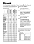
1
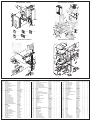
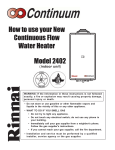
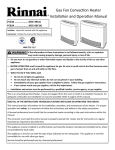
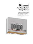
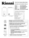
Gas Pressure Setting
Remote Controller
Ensure gas pressure check under Commissioning has been
completed first! The regulator is electronically controlled and
factory pre-set. Under normal circumstances it does not require
adjustment during installation. Make adjustments only if the unit is
not operating correctly and all other possible causes for incorrect
operation have been eliminated.
In Use Indicator
Indicates that hot water
is being supplied.
Priority Indicator
Indicates that this
controller is setting the
water temperature.
Temperature Display
Indicates temperature
setting or flashes error
code.
1.
2.
3.
4.
Turn OFF the gas supply.
Turn OFF the 120 V power supply.
Remove the front panel from the appliance.
Check the gas type using the data plate on the side of the unit.
If using a spare PC board, check that the gas type switches are
in the correct position (dip switch 1 of SW2: ON for natural gas,
NG, and OFF for propane, LPG). See dip switch settings
section below. (ON is towards the right and OFF is towards the
left.)
5. Attach the pressure gauge to the burner test point, located on
the gas control (Fig. 2).
6. Turn ON the gas supply.
7. Turn ON the 120 V power supply.
8. If a controller is installed, turn the unit ON with the controller.
Select the maximum delivery temperature and open all
available hot water taps at full.
9. Set the unit to “Forced Low” combustion by setting No. 7 dip
switch of the SW1 set to ON (Fig. 3).
10. Check the burner test point pressure.
11. Remove the rubber access plug and adjust the regulator screw
on the modulating valve (Fig. 4) as required in Table 1.
Replace the rubber access plug.
12. Set the unit to “Forced High” combustion by setting both No. 7
and No. 8 dip switches of the SW1 set to ON (Fig. 5). Ensure
maximum water flow.
13. Check the burner test point pressure.
14. Adjust the high pressure potentiometer (POT) on the PC board
as required to the pressure shown in Table 1.
15. Return the unit to normal operation by setting dip switches 7
and 8 of the SW1 set back to OFF (Fig. 6). Close all water
taps.
16. Turn OFF the gas supply and 120 V power supply.
17. Remove the pressure gauge and install sealing screw.
18. Turn ON the gas supply and 120 V power supply.
19. Operate the unit and check for gas leaks at the test point.
20. Install the front panel.
Priority Button
When no water is
being supplied,
pressing this button
allows this controller to
set the water
temperature.
Thermostat
ON/OFF Button
Diagnostic Use of the Controller
1. To display error codes, press the ON/OFF button followed by
the ▲ thermostat button to cycle through the error codes.
2. To display the water flow through the water heater, press the ▲
thermostat button (hold for 2 seconds) and then press the
ON/OFF button while continuing to hold the ▲ thermostat
button.
3. To display the outlet water temperature, press the ▼ thermostat
button (hold for 2 seconds) and then press the ON/OFF button
while continuing to hold the ▼ thermostat button.
To Change the Temperature Scale (ºF / ºC)
With the water heater turned off, press and hold the ON/OFF
button until the display changes to the other temperature scale
(about 5 seconds).
To Turn Off the Controller Sound (Mute)
To turn the sound off (mute), press and hold both the ▲ and ▼
thermostat buttons until a “beep” is heard (about 5 seconds).
Gas Pressure Setting
BURNER TEST POINT
NOTE: For additional installation and commissioning information refer
to the Operation and Installation Manual.
High Pressure
Potentiometer
WARNING
SW1
This appliance must be installed, serviced and removed by a trained
and qualified person. During pressure testing of the consumer piping,
ensure gas valve is turned off before unit is shut off. Failure to do so
may result in serious injury to yourself or damage to the unit.
APPLIANCE OPERATING PRESSURES
NAT.G
Spare Parts
Only
Table 1
Gas Inlet
Min./Max
Water
Inlet Max
1
SW2
LPG
Forced Low
NAT.G
LPG
Forced High
NAT.G
LPG
R50LSi
2.0"W.C. 3.2"W.C.
R75LSi
5"W.C.
8"W.C.
150 PSI /10.5"W.C. /13.5"W.C. 0.52"W.C. 0.92"W.C. 2.7"W.C. 4.4"W.C.
R94LSi
3.3"W.C. 5.0"W.C.
There are a number of (live) tests that are required when fault
finding this product. Extreme care should be used at all times to
avoid contact with energized components inside the water heater.
Only trained and qualified service technicians should attempt to
repair this product. Before checking for resistance readings,
disconnect the power source to the unit and isolate the item from
the circuit (unplug it).
(SV1, SV2, SV3 and POV) Gas valve and Modulating solenoids: (Set meter above 2K)
Wire color
Voltage
Resistance
Connector # Pin #'s
(Main) Pink - Black 11 ~ 13 VDC
36.8 ~ 44.8 ohms
H5
6-7
(SV1) Black - Yellow 11 ~ 13 VDC
36.8 ~ 44.8 ohms
H6
5-6
(SV2) Black - Blue
11 ~ 13 VDC
36.8 ~ 44.8 ohms
H7
4-6
(SV3) Black - Brown 11 ~ 13 VDC
36.8 ~ 44.8 ohms
H8
3-6
(POV) Pink - Pink
2 ~ 15 VDC
67 ~ 81 ohms
H3
9 - 10
(M) Water Flow Control Device Servo or Geared Motor:
Red - Blue
11 ~ 13 VDC
22 ~ 28 ohms
F7
9 - 10
Grey - Brown
4 ~ 6 VDC
N/A
F7
5-7
Grey - Yellow
N/A
N/A
F7
5-8
NOTE: The grey wire listed above turns to black at F connector on the PCB.
(QS) Water Flow Sensor:
Black - Red
11 ~ 13 VDC
5.5 ~ 6.2 K ohms
F2
1-3
Yellow - Black
4 ~ 7 VDC
1 ~ 1.4 Mega ohms F2
2-3
By-pass Flow Control (By-pass servo model ONLY):
Brown - White
Orange - White
2 ~ 6 VDC
15 ~ 35 ohms
Yellow - White
(Unit in operating mode)
Red-White - Ground
(IG) Ignition System:
Grey - Grey
90 ~ 110 VAC
N/A
(FM) Combustion Fan Motor:
Red - Black
6 ~ 45 VDC
White - Black
5 ~ 10 VDC
Yellow - Black
11 ~ 13 VDC
N/A
9.2 ~ 9.4 K ohms
3.5 ~ 3.9 K ohms
G1
G1
G1
G1
1-5
2-5
3-5
4-5
C1
1-2
E1
E1
E1
1-2
2-4
2-3
Set your meter to the hertz scale. Reading across the white and black wires at terminals 2 and 4
you should read between 60 and 420 hertz.
Thermal Fuse / Overheat Switch:
F6
Red - Red
11 ~ 13 VDC
Below 1 ohms
F6 - H12
H1
Flame Rod:
03 Power interruption during Bath fill (Water will not flow when
Check all thermistors by inserting meter leads into each end of the
thermistor plug. Set your meter to the 20 K scale and read
resistance. Applying heat to the thermistor bulb should decrease
the resistance. Applying ice to the thermistor bulb should increase
the resistance. See below for examples of typical temperatures and
resistance readings.
59°F = 11.4 ~ 14KΩ
140°F = 2.2 ~ 2.7KΩ
Example:
221°F = 0.6 ~ 0.8KΩ
F5
3-4
F4
3 - 11
F3
3 - 12
D2
D1
1-3
1-3
With the power off you can check the continuity through the surge
protector. Place a meter lead on the top pin #1 of the surge
protector and pin #3 on the bottom of the surge protector. Check
across the top pin #3 and bottom pin #1. If you read continuity
across these two points then the surge protector is good. If you do
not get continuity then replace the surge protector.
Remote Controls:
Terminals B1
10 ~ 13 VDC
1.5 ~ 3.0 K ohms
B
• Check for foreign materials in combustion chamber and/or
exhaust piping.
• Turn off all hot water taps. Press ON/OFF twice.
• Check for clogged heat exchanger.
10 Air Supply or Exhaust Blockage
32 Outgoing Water Temperature Sensor Fault
Ensure Rinnai approved venting materials are being used.
Check that nothing is blocking the flue inlet or exhaust.
Check all vent components for proper connections.
Ensure vent length is within limits.
Ensure condensation collar was installed correctly.
Verify dip switches are set properly.
Check fan for blockage.
•
•
•
•
•
•
•
1-3
Frost Protection:
This unit has frost protection heaters mounted at different points to
protect the water heater from freezing. The heaters located on the
hot water outlet line should have a resistance reading of 180-207
ohms through each of these heaters. The heater located on the
heat exchanger piping should have a resistance reading of 156-180
ohms and the one located in the water flow sensor valve should
have a resistance reading 24-28 ohms.
Amp Fuses:
This unit has two inline (3) amp glass fuses. Remove the fuse and
Place one lead of your meter to the flame rod and the other to ground.
check continuity through it. If you have continuity through the fuse
With the unit running you should read between 5-150 VAC. Set your
then it is good. Otherwise the fuse is blown and must be replaced.
meter to the µ amp scale and series your meter in line with the flame
rod. You should read 1 µ amp or greater for proper flame circuit. In
the event of low flame circuit remove the flame rod and check for
carbon or damage.
33 Heat Exchanger Outgoing Temperature Sensor Fault
or cylinder.
Ensure gas type and pressure is correct.
Ensure gas line, meter, and/or regulator is sized properly.
Bleed all air from gas lines.
Verify dip switches are set properly.
Ensure appliance is properly grounded.
Disconnect EZConnect or MSA controls to isolate the problem.
Ensure igniter is operational.
Check igniter wiring harness for damage.
Check gas solenoid valves for open or short circuits.
Remove burner cover and ensure all burners are properly
seated.
• Remove burner plate and inspect burner surface for
condensation or debris.
•
•
•
•
•
•
•
•
•
•
12 Flame Failure
Check sensor wiring for damage.
Measure resistance of sensor.
Clean sensor of scale build up.
Replace sensor.
•
•
•
•
• Check that the gas is turned on at the water heater, gas meter,
34 Combustion Air Temperature Sensor Fault
Check for restrictions in air flow around unit and vent terminal.
Check sensor wiring for damage.
Measure resistance of sensor.
Clean sensor of scale build up.
Ensure fan blade is tight on motor shaft and is in good
condition.
• Replace sensor.
•
•
•
•
•
52 Modulating Solenoid Valve Signal Abnormal
• Check modulating gas solenoid valve wiring harness for loose
or damage terminals.
• Measure resistance of valve coil.
61 Combustion Fan Failure
• Check that the gas is turned on at the water heater and gas
meter. Check for obstructions in the flue outlet.
Ensure gas line, meter, and/or regulator is sized properly.
Ensure gas type and pressure is correct.
Bleed all air from gas lines.
Ensure proper Rinnai venting material was installed.
Ensure condensation collar was installed properly.
Ensure vent length is within limits.
Verify dip switches are set properly.
Ensure appliance is properly grounded.
Disconnect keypad.
Disconnect EZConnect or MSA controls to isolate the problem.
Check power supply for loose connections.
Check power supply for proper voltage and voltage drops.
Ensure flame rod wire is connected.
Check flame rod for carbon build-up.
Disconnect and re-connect all wiring harnesses on unit and PC
board.
• Check all components for electrical short.
• Check gas solenoid valves for open or short circuits.
• Remove burner plate and inspect burner surface for
condensation or debris.
•
•
•
•
•
•
•
•
•
•
•
•
•
•
•
• Ensure fan will turn freely.
• Check wiring harness to motor for damaged and/or loose
connections.
• Measure resistance of motor winding.
65 Water Flow Servo Faulty (does not stop flow properly)
If blank screen is present on remote control then the flow control
has shorted out. Unplug flow control. If remote lights up and unit
starts operating then replace flow control assembly.
71 SV0, SV1, SV2, and SV3 Solenoid Valve Circuit Fault
• Check wiring harness to all solenoids for damage and/or loose
connections.
• Measure resistance of each solenoid valve coil.
72 Flame Sensing Device Fault
• Ensure flame rod is touching flame when unit fires.
• Check all wiring to flame rod for damage.
• Remove flame rod and check for carbon build-up; clean with
sand paper.
• Check inside burner chamber for any foreign material blocking
flame at flame rod.
• Measure micro amp output of sensor circuit with flame present.
• Replace flame rod.
•
•
•
LC Scale Build-up in Heat Exchanger (when checking
used.
maintenance code history “00” is substituted for “LC”)
Check for restrictions in air flow around unit and vent terminal.
• Flush heat exchanger. Refer to instructions in manual.
Check for low water flow in a circulating system causing shortcycling.
• Replace heat exchanger.
Ensure dip switches are set to the proper position.
No Code (Nothing happens when water flow is activated.)
Check for foreign materials in combustion chamber and/or
• Clean inlet water supply filter.
exhaust piping.
• On new installations ensure hot and cold water lines are not
Check heat exchanger for cracks and/or separations.
reversed.
Check heat exchanger surface for hot spots which indicate
•
Check for bleed over. Isolate unit from building by turning off
blockage due to scale build up. Refer to instructions in manual
hot water line to building. Isolate the circulating system if
for flushing heat exchanger.
present. Open your pressure relief valve; if unit fires, there is
Measure resistance of safety circuit.
bleed over in your plumbing.
Ensure high fire and low fire manifold pressure is correct.
•
Ensure you have at least the minimum flow rate required to fire
Check for improper conversion of product.
unit.
• Ensure turbine spins freely.
• Measure the resistance of the water flow control sensor.
• Remote control does not light up but you have 12 VDC at the
terminals for controls.
Wiring Diagram
BR
O
Y
R
W
BY-PASS FLOW
CONTROL DEVICE
FREEZE PROTECTION
OPTION
WATER FLOW
SENSOR
F2
QS
R
Y
BK
COLOR CODING
G1
BY-PASS SERVO MODEL ONLY
F1
W Y O R BR
5
G
1
(CN7)
MAX
INDOOR MODEL ONLY
W
W
HEAT EXCHANGER
THERMISTOR
W
W
OUTGOING WATER
THERMISTOR
F7
W
W
F3
F4
F5
R BK
O
W
O
Dip SW1
(CN9)
(CN5)
E
4
W
Y
BK
R
H
1
12
Y R
W BK
B
1
(CN2)
P P Y BR Y
R P
BK BL
F6
THERMAL FUSES
R
R
OVERHEAT
SWITCH
H1
Gas type
Spare Parts Only
1
2
3
4
5
6
O
F
F
FM
Gas pressure
Dip SW2
B1
1
BK
BK
3
(CN1)
C
COMBUSTION FAN
GY
GY
(CN3)
Y
D
D3
1
FROST SENSING
SWITCH
3
H5
MAIN SOLENOID VALVE
SV0
SOLENOID VALVE 1
SV1
SURGE
PROTECTOR
Y
BK
H7
SOLENOID VALVE 2
SV2
SOLENOID VALVE 3
SV3
BL BL
(W) (W)
P
BK
H6
BL
BR
BL
BK
H8
BR
BK
G/Y
GND
D1
1
3
3
1
W
W
2
W BK
3
Off
Off
Level 0
0-2000ft
(0-610m)
Off
On
Level 1
2001-5200ft
(610-1585m)
On
Off
Level 2
5201-7700ft
(1585-2347m)
On
On
Level 3
7701-10200ft
(2347-3109m)
ANTI-FROST HEATER
AC120V
HOT
NEUTRAL
GROUND
R50LSi
R75LSi
R94LSi
NOTES
High Altitude
D4
BL BL
FUSE
(3A)
G/Y
GND
D5
ANTI-FROST HEATER
D2
BK
W
DO NOT adjust the other dip switches unless specifically instructed
to do so. Incorrect Dip Switch Settings can cause the Rinnai water
heater to operate in an unsafe condition and may damage the water
heater and void the warranty.
SW
No.
GND
BL
BR
H4
SPARK
ELECTRODE
IG
IGNITER
(CN4)
H3
REMOTE CONTROLLER
C1
GY
GY
R
R
POV PP
FLAME ROD
1
2
3
4
5
6
7
8
O
F
F
1
R Y
W
W
E1
W R BK
3
WW
(CN12)
WATER FLOW
CONTROL DEVICE
A
1
P BL BR
W
P
F
GY
13
GY
R
BL
Y
BR
R
BL
BR
Y
GY
MODULATING
SOLENOID VALVE
WARNING
MODULATING VALVE
CURRENT ADJUSTING
MIN
AIR TEMPERATURE
THERMISTOR
W :White
BK:Black
BR:Brown
R :Red
BL:Blue
Y :Yellow
P :Pink
O :Orange
G :Green
GY:Gray
for REU-EZC
(Optional)
G
R
R
Y
BK
H2
High Altitude
Check sensor wiring for damage.
Measure resistance of sensor.
Clean sensor of scale build up.
Replace sensor.
•
•
•
•
11 No Ignition
•
•
Outgoing Water Thermistor:
White - White
N/A
See example above
Heat Exchanger Temperature Thermistor:
Pink - White
N/A
See example above
Intake Air Thermistor (Indoor model ONLY)
Orange - White
N/A
See example above
Surge Protector:
Black - White
108 ~ 132 VAC
N/A
Blue - Brown
108 ~ 132 VAC
N/A
cycling.
power returns)
•
•
86°F = 6.4 ~ 7.8KΩ
113°F = 3.6 ~ 4.5KΩ
• Check for restrictions in air flow around unit and vent terminal.
• Check for low water flow in a circulating system causing short-
• Service Call
•
•
Heat Exchanger and Outgoing Water Temperature
Thermistors:
Important Safety Notes
16 Over Temperature Warning
• Check gas type of unit and ensure it matches gas type being
With all gas appliances in operation at maximum gas rate, the
flowing inlet pressure at the incoming test point on the Rinnai
water heater should read 5” W.C. - 10.5” W.C. on natural gas
and 8” W.C. - 13.5 W.C. on propane gas. If the pressure is
lower, the gas supply is inadequate and the unit will not operate
to specification. Check the gas meter regulator and pipework for
correct operation/sizing and correct as required.
Troubleshooting
02
14 Thermal Fuse
Regulator adjustment
screw access plug
Commissioning
Error Codes
No burner operation during freeze protection mode
070 00012 36781 1
U287-079(00)
EXPLODED VIEW - CABINET
005
EXPLODED VIEW - INTERNALS
001
800
144
002
148
147
145
146
139
141
010
017
142
140
009
141
801
711
716
135
802
710
143
709
810
717
011
004
014
114
003
002
138
708
006
117
132
119
121
707
MC-91-1US
MC-100V-1US
718
103
118 116
800
012
137
136
016
008
122
MC-502RC-1US
706
113
811
812
719
131
MCC-91-1US
BC-100V-1US
803
110
125
EXPLODED VIEW - ELECTRICAL
EXPLODED VIEW - INTERNALS
725
729
100
818
101
721
413
720
401
e
712
813
724
727
403
713
815
805
723
804
814
409
805
404
815
722
726
730 810
822
408 410 816
411
702
807
e
819
700
821 817
102
820
402
101
813
400
701
820
703
Number
001
002
003
004
005
006
008
009
010
011
012
014
016
017
100
101
102
103
103
110
110
113
114
116
117
118
119
121
122
125
131
132
135
136
137
138
139
140
Description
Main Body (FF)
Wall mounting bracket
Rubber Bushing
Connection Reinforcement Panel
Heat Protection Plate
Front Panel
Front Panel Gasket-1
Remote Controller Ass'y
Remote Controller Bracket
Side Cover
Side Cover Rid
Rubber Bushing
Packing
Side Cover Assy
Gas Control Assembly
Test Port Set Screw
Gas Connection (3/4" NPT)
Burner Unit Assembly (LPG)
Burner Unit Assembly (NG)
Manifold Assembly (LPG)
Manifold Assembly (FF-NG)
Pressure Point Sealing Screw
Combustion Chamber Sightglass Plate
Electrode
Flame Rod
Electrode Packing
Electrode Holder
Tube Joint
Vent Tube
Fan Motor All Assembly
Rubber Boot Bracket Right
Combustion Chamber Fan Bracket
Air Inlet Box All Assembly
Rubber Boot Bracket Left
Rubber Boot
Rubber Boot Clamping Ring
Air Inlet Duct
AirInlet Box Frame
412
814
715
405
Quantity
Parts Number
R94LSi R75LSi R50LSi
1
1
1
109000010
2
2
2
109000024
1
1
1
U245-125
1
1
1
109000023
1
1
1
U245-107
1
1
1
109000012
2
2
2
U245-3185-1
MC-91-1US-S-FLVA
1
1
1
103000011
1
1
1
U245-3121X05
2
2
2
U245-3122X02
4
4
4
CF79-41020-A
1
1
1
AU105-113
1
1
1
109000022
2
2
2
106000010
1
1
1
AU39-965X01
2
2
2
CU195-1866
1
1
1
106000011
1
1
1
106000012
1
1
1
106000013
1
1
1
106000014
1
1
1
C10D-5
1
1
1
106000016
1
1
1
H73-120
1
1
1
105000010
1
1
1
AH66-398X01
1
1
1
AH66-393
1
1
1
U242-312
1
1
1
AU161-665-CX01
1
1
1
108000010
1
1
1
U245-566
1
1
1
U245-255X01
1
1
1
108000013
1
1
1
U245-408
1
1
1
U245-409X01
1
1
1
U245-567
1
1
1
108000014
1
1
1
U245-434X02
1
1
1
PARTS LIST
Number
141
142
143
143
144
144
145
146
147
148
400
401
401
402
403
404
404
405
408
409
410
411
412
413
700
700
701
701
702
703
706
707
708
709
710
711
712
713
715
Description
Joint Exhaust Tube Frame Supporter
Air Inlet Box Cover
Heat Exchanger Assembly
Heat Exchanger Assembly
Flue Connection Assembly
Flue Connection Assembly-Male (optional)
O-ring
O-ring
Pipe Seal
Cap
Water Inlet (3/4" NPT)
Water Flow Servo & Sensor Assembly
Water Flow Servo & Sensor Assembly
Rectifier
By-pass Servo Assembly
Stop Bracket
Stop Bracket
Plug Band
Hot Water Outlet (3/4" NPT)
Stop Bracket
Plug Band (small)
Drain Valve
Water Filter Assembly
Cover
PCB
PCB
Surge Protector
Surge Protector with terminal (optional)
PCB Cover-side
PCB Cover-front
Ignitor
High Tension Cord
Electrode Sleeve
Thermistor
Thermistor Clip Large
Thermal Fuse Clip
Frost Sensing Switch
Anti Frost Heater (120V)
Valve Heater (120V) Assembly
Quantity
Parts Number R94LSi R75LSi R50LSi
2
2
2
U245-435
1
1
1
U245-419
1
107000010
1
1
107000011
1
1
1
108000015
1
1
1
108000016
1
1
1
108000017
1
1
1
108000018
1
1
1
108000019
1
1
1
108000020
1
1
1
H73-501-2
1
107000014
1
1
107000015
1
1
1
M8D1-15X01
1
M6J-1-4
2
AH69-310
1
1
AU195-321X01 1
1
1
109000018
1
1
1
U245-865-3
AU162-1876X01 1
1
1
109000019
1
1
1
107000021
1
1
1
H98-510-S
1
1
1
109000020
1
1
1
105000071
1
105000072
1
1
105000067
1
1
1
BU195-1873-2
1
1
1
105000015
1
1
1
105000017
1
1
1
105000068
1
1
1
105000019
1
1
1
AU206-218
1
1
1
105000020
1
1
1
CP-90172
1
1
1
U217-676X02
5
5
5
U242-511
1
1
1
105000022
1
1
1
105000024
1
1
1
Number
716
717
718
719
720
721
722
723
724
724
725
726
727
729
730
800
801
802
803
804
805
810
811
812
813
814
815
816
817
818
819
820
821
822
888
889
900
900
900
Description
Antifrost Heater Clip B
Antifrost Heater Clip A
Antifrost Heater Clip C
Inlet Air Thermistor
Power Cord
Fuse Harness(FF)
Power Harness
Solenoid Valve Harness
Sensor Harness
Sensor Harness
Thermal Fuse Harnes Assembly
Ignitor Harness
Flow Sensor
Remote Controller Harness
Thermistor
Screw
Screw
Resin Washer
Screw
Thermistor Stop Screw
Screw
O-ring
O-ring
O-ring
O-ring
O-ring
O-ring
O-ring
O-ring
Packing
Screw
Screw
Screw
Screw
Manual
Tech Sheet
Front Panel Label (94)
Front Panel Label (75)
Front Panel Label (50)
Quantity
Parts Number R94LSi R75LSi R50LSi
2
2
2
CF29-742
1
1
1
AU111-653
1
1
1
AU100-721
1
1
1
105000029
1
1
1
CP-90580
1
1
1
105000069
1
1
1
105000033
1
1
1
105000034
1
105000035
1
1
105000036
1
1
1
105000039
1
1
1
105000040
1
1
1
105000041
1
1
1
105000042
1
1
1
H111-650
8
8
8
ZIHD0510UK
4
4
4
CP-30580
4
4
4
CF83-41430
3
3
3
108000021
1
1
1
U217-449
3
2
2
ZAA0408UK
2
2
2
M10B-2-4
1
1
1
M10B-2-3
1
1
1
M10B-13-4
2
1
1
M10B-2-18
2
2
2
M10B-2-16
2
1
1
M10B-2-14
1
1
1
M10B-2-7
1
1
1
M10B-1-24
2
2
2
C36E1-6
2
2
2
ZAG0512UK
4
4
4
ZQAA0514UK
2
2
2
ZQAA0508UK
3
3
3
ZBA0512UK
1
1
1
100000113
1
1
1
100000115
1
100000014
1
100000015
1
100000017