1
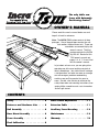
The only table saw
fence with Automatic
Positioning Control TM
OWNER’S MANUAL
Please read this owner’s manual before use and
keep it at hand for reference.
Note: The INCRA TS III system consists of three
packages. One of the packages contains the rails
and another, the base mount unit. These two
assemblies are covered fully by this
owner’s manual. The third
package contains the INCRA
Jig Ultra 32. Read all of this
TS III owner’s manual and
pages 2, 3, 6, 7, 18 and 19 of
the Ultra owner’s manual.
In just about an hour or so, you are going to be
operating one of the most exciting new tools in
today’s woodshops. Your table saw will undergo
a transformation, and what was once an average
saw will emerge a precision woodworking
machine, one you’ll be proud of for years to
come. So take a few minutes to read over the
safety information and mounting instructions, then
grab a phillips screwdriver and a set of wrenches
and let’s get started.
CONTENTS
Safety . . . . . . . . . . . . . . . . . . . 2
Blade Guard Adjustments . . . . . . 11
Fasteners and Hardware Lists . . . . 2
Extension Table
Rail Assembly . . . . . . . . . . . . . . 4
Auxiliary Fence Mounting
Base Mount Assembly . . . . . . . . . 6
Maintenance . . . . . . . . . . . . . . 12
Fence Assembly . . . . . . . . . . . . . 8
Warranty . . . . . . . . . . . . . . . . . 12
Final Calibration
. . . . . . . . . . . .9
. . . . . . . . . . . . 11
. . . . . 12
SAFETY
Important safety instructions for using the INCRA TS III.
■
Before using the INCRA TS III, read and follow all
of the instructions and safety information in this
manual.
■
When using the INCRA TS III in conjunction with
any other tool, first read and follow all instructions
and safety information in that tool’s owner’s manual.
■
Never let any part of the INCRA TS III interfere with
another tool’s safety guards or other safety
equipment.
■
Before using your INCRA TS III, make sure all
mounting screws are tight and that the black
clamping knobs are securely tightened to the rails.
■
Always turn off the power and make sure that the
blade is fully stationary before changing the setting
on any part of the INCRA TS III.
FASTENERS
■
Always keep both hands behind the fence when
moving the INCRA TS III to a new setting.
■
Before making a cut, always make sure that the
carriage clamp is fully engaged and that the
rail hook thumbscrew is securely tightened.
■
Use appropriate safety devices. Keep hands clear
of the saw blade! Always use a push stick, rubber
soled push block, or other safety devices to keep
your hands safely away from the saw blade.
■
Never let the saw blade come into contact with
any part of the INCRA TS III or INCRA Jig Ultra.
■
Wear safety glasses, hearing protection, and follow
all normal shop safety practices.
■
Never operate your table saw without a blade guard.
(actual size)
Mounting Bracket Hardware Pack
3⁄ 8
6 each
– 16 x 11⁄ 2"
hex bolt
6 each
3 ⁄ 8"
flat washer
2 each
– 24 x 1"
hex bolt
(Delta Unisaw)
4 each
– 18 x 11 ⁄ 2"
hex bolt
3⁄ 8
5 ⁄ 16
4 each
5 ⁄ 16"
flat washer
4 each
5 ⁄ 16"
lock washer
6 each
3 ⁄ 8"
lock washer
Note:
Extra hardware is provided in this pack to
ensure compatibility with a wide variety of
table saws. Only four of the bolts will be
used in a typical installation.
INCRA Woodworking Tools & Precision Rules
6 each
– 16
hex nut
3/8
4 each
– 18
hex nut
5 ⁄ 16
2
Rail Hardware Pack
Note:
Each hardware pack is labeled and bagged separately.
Open each pack as it is called for in the instructions to
simplify assembly.
Base Mount and Fence Glide Hardware Pack
4 each
– 16 x 3 ⁄ 4"
clamping knob
3⁄ 8
6 each
– 16 x 3 ⁄ 4"
hex bolt
3⁄ 8
4 each
– 16 x 3 ⁄ 8"
socket head set screw
3⁄ 8
6 each
– 20 x 1⁄ 2"
socket head cap screw
1⁄ 4
6 each
1⁄ 4"
flat washer
4 each
– 16 x 1⁄ 2"
hex bolt
3⁄ 8
6 each
20
square nut
1⁄ 4 –
10 each
3 ⁄ 8"
flat washer
8 each
#10 – 32 x 7⁄ 16"
phillips flat head screw
10 each
3 ⁄ 8 – 16
rectangular nut
8 each
#10 – 32
hex nut
ULTRA Mounting Hardware Pack
6 each
#10 – 32 x 1⁄ 2"
phillips pan head screw
4 each
3⁄ 16 "
thick nylon washer
INCRA TS III Owner’s Manual
4 each
– 16
dual pilot rectangular nut
3⁄ 8
6 each
#10 – 32
hex nut
6 each
#10
flat washer
3
RAIL ASSEMBLY
Unplug your table saw and remove the existing fence,
including the front and rear support rails, mounting
brackets, and the blade guard.
FIG. 1
Use appropriate mounting
hardware from the Mounting
Bracket Hardware Pack to
attach brackets
(See Details 1A and 1B)
Attach rail
mounting brackets
Note: The blade guard must be reinstalled after you have
finished mounting the INCRA TS III to your table saw.
1
Attach mounting brackets
Attach (4) mounting brackets to the cast iron surface
of your table saw using the supplied hardware. See Fig. 1.
The Mounting Bracket Hardware Pack contains a variety of
fasteners which will work with most table saws. Use the
largest bolts in the pack that will fit your saw’s existing
mounting holes. If the holes in your table saw are
threaded, use the bolt/lock washer/washer arrangement
shown in Detail 1A. If the mounting holes are not
threaded, use the bolt/washer/lock washer/nut arrangement
shown in Detail 1B. Position the mounting brackets 1 ⁄4"
below the table top as shown in Details 1A and 1B and
snug the fasteners to hold the brackets in place. DO NOT
TIGHTEN THE BOLTS AT THIS TIME. (Discard any
remaining fasteners from the Mounting Bracket Hardware
Pack.)
Rail
mounting
brackets
DETAIL 1A
Table saw top
1⁄ 4"
FIG. 2
Loosely
attach rail
bolts
Threaded holes
in table saw
Flat
washer
Mounting
bracket
Lock washer
DETAIL 1B
Table saw
top
1⁄ 4"
3 ⁄ 8 – 16
Through holes
in table saw
(Not threaded)
rectangular nut
3 ⁄ 8" flat washer
3 ⁄ 8 – 16
Flat washer
x 3⁄ 4" hex bolt
Hex
nut
Lock washer
2
FIG. 3
Loosely attach rail bolts
3 ⁄ 8"
Open the Rail Hardware Pack. Add a
flat washer
to each of (4) 3 ⁄ 8 –16 x 3 ⁄ 4" hex bolts. Place the bolts
through the holes in the mounting brackets and loosely
attach the 3 ⁄ 8 –16 rectangular nuts. See Fig. 2 above.
3
Orient rails so that web is vertical
and off center T-slot faces the saw
as shown below
Front and rear
rail orientation
Web
Front rail
Table saw
Rear rail
Slide rails onto mounting
brackets and tighten bolts
Carefully slide the rails onto the mounting brackets so that
the rectangular nuts are captured in the T-slot on the bottom
of the rail. Fig. 3 shows the correct orientation for the front
and back rails. Approximately center the length of the rails
on your table saw and tighten the mounting bolts that
secure the rails to the brackets.
INCRA Woodworking Tools & Precision Rules
Off center T-slot faces table saw
Web
4
4
Set final mounting bracket position
Clamp the (2) TS III base clamps to the front rail as
shown in Fig. 4 and loosen the bolts that secure the
mounting brackets to your table saw. The rail and mounting
brackets will drop down until the base clamps touch the top
of your saw, Fig. 5. This locates the final mounting bracket
position. Tighten the bolts that secure the mounting brackets
to your table saw. Repeat for the rear rail.
FIG. 5
Base clamp
Tighten
mounting
bracket
bolts
Table saw
top
FIG. 4
Set final mounting
bracket position
First: Clamp base clamps to
rail. Use clamp pads to avoid
marring anodized surfaces
Mounting
bracket
Mounting
bracket
Rail
Base clamps
Clamp pad
Mounting bracket is at
correct level when base
clamp touches table top
Mounting
bracket bolt
5
Set final rail position
Loosen the bolts that secure the rails to the mounting
brackets and slide the rails so that they extend 7" beyond
the left hand extension wing of your table saw as shown in
Fig. 6. Push the rail against the short vertical leg on the
mounting bracket and tighten the bolts that hold the rail in
place. See Fig. 7 below.
FIG. 7
Second: Loosen both
mounting bracket bolts.
Brackets will lower slightly
FIG. 6
Left hand extension wing
Set final rail position
7"
Short vertical leg
Tighten rail
mounting
bolts
Rail
Rail mounting bolt
Push rail against
short vertical leg
and tighten rail
mounting bolts
Rails should
extend 7" beyond
left hand extension
wing
Custom Setups
The rail positions described above will provide support
for the base of the TS III for work on either the left or
right side of the blade. Left hand range is about 16"
and right hand range is 31". These same rail positions
will accommodate the optional 18" router table on the
left or 24" router table on the right.
6
If you wish to customize the setup to suit your needs,
just slide the rails left or right as necessary. Keep in
mind that sliding the rails to the right subtracts from
your range to the left and sliding the rails to the left
subtracts from your range to the right.
Slide stop positioner and base clamping
knob assemblies onto the rails
Base clamping knob - Add a 3⁄ 16" thick nylon washer to each of (4)
base clamping knobs and loosely attach a 3 ⁄ 8 –16 dual pilot
rectangular nut. The flat side of the rectangular nut should face the
knob. Thread a 3 ⁄ 8 –16 x 3 ⁄ 8 " set screw into the remaining hole on
each rectangular nut. Slide the base clamping knob assemblies
onto the right hand end of each rail as viewed from the operator’s
side of the table saw. Do not tighten set screws or knobs at this
time. See Fig. 8.
Stop positioner - Add a 3 ⁄ 8" flat washer to each of (4) 3 ⁄ 8 –16 x 1⁄ 2"
hex bolts, then loosely attach a 3 ⁄ 8 –16 rectangular nut. Slide one
stop positioner into each end of both rails, capturing the rectangular
nut in the T-slot as shown. Do not tighten bolts at this time.
INCRA TS III Owner’s Manual
FIG. 8
Assembly
Left end of rail
Right end
of rail
3⁄ 8
– 16 dual pilot
rectangular nuts
3⁄ 8 – 16
rectangular
nut
3⁄ 8" flat
washer
T-slot
Base clamping knob
3⁄ 8 – 16
x 3⁄ 8" set screws
Do not tighten
fasteners at this time
3⁄ 16" thick
nylon washer
3⁄ 8 – 16
x 1⁄ 2"
hex bolt
5
BASE MOUNT ASSEMBLY
Note: The base support panel used in the base mount
assembly is designed for use with table saws having a front
to back measurement of up to 28". If your table saw
1
Attach glide pads to underside of
base clamps
measures greater than 28" a custom cut support panel is
available. For details, e-mail us at [email protected] or
call us at the number listed at the bottom of page 12.
FIG. 9
Adhere glide pad to
underside of base clamp
Peel the adhesive backing from the glide pad and adhere to the
base clamp as shown in Fig. 9. Repeat for remaining base clamp.
Base clamp
Note: Do not attach glide pads until after main rail
installation has been completed. (See page 5, Figs. 4 and 5).
Remove
FIG. 10
endcaps
from base
support panel
2
Adhesive
backed glide pad
See Fig. 10 at right.
Base support
panel
3
Endcap
Attach one base clamp to end of
base support panel
FIG. 11
Base support
panel
Attach one base
clamp to end of
base support panel
Open the Base Mount & Fence Glide Hardware Pack. Insert
the (8) #10-32 x 7/16" phillips flat head screws in the
countersunk holes of both base clamps and loosely thread on
the #10-32 hex nuts. Slide the hex nuts on one of the base
clamps into the (4) T-slots on the base panel. Fig. 11. Leave
#10-32
about 3/8" between the panel end and the vertical surface on
hex nuts
the base clamp as shown in Detail 11A and tighten the
screws. Set aside the
Base support panel
Detail 11A
remaining fasteners from
3⁄ 8"
the Base Mount & Fence
Base clamp
Glide Hardware Pack for
#10– 32 x 7⁄ 16"
use in Steps 2 and 3 on
phillips flat head screw
page 8.
Attach the INCRA Jig Ultra to base
support panel and loosely attach
remaining base clamp
4
Open the Ultra Mounting Hardware Pack. Place #10 washers
on each of the (6) #10 - 32 x 1/2" phillips pan head screws. Insert
four of the screws through the slotted holes on the Ultra base
and loosely thread a #10 - 32 hex nut onto each screw. Insert
the remaining two screws through the two inside holes located in
the middle of the Ultra’s base and attach hex nuts. Slide the
hex nuts on all six screws into the T-slots on the base support
panel. The (4) screws/nuts in the slotted holes slide into the
outer T-slots. The (2) screws/nuts inside the Ultra’s base slide
into the inner T-slots. See Fig. 12 and Detail 12A.
Center the Ultra’s base on the support panel. (Edge of Ultra
should be about 10 5/8" from end of panel.) Use a square to
align the Ultra base at 90° to the panel and
tighten the screws installed in the slotted
Detail 12A
holes only. Do not tighten the two screws
inside the Ultra’s base at this time. Slide
the hex nuts on the remaining base clamp
Screws in slotted
into the T-slots on the support panel.
FIG. 12
Attach ULTRA to
base support panel
Do not tighten these two
screws at this time
#10– 32 x 1⁄ 2" phillips pan
head screws with washers
Machinist square
Base support
panel
Base clamp
holes – use outer T-slots
INCRA Woodworking Tools & Precision Rules
Base
clamp
10 5⁄ 8"
Hex nuts for screws
captured in T-slots
on support panel
Screws inside ULTRA base – use inner T-slots
Base support panel
6
5
Align base mount assembly
parallel to miter slot
FIG. 13
Align base mount assembly parallel to miter slot
Take the base mount assembly to the
table saw and as you lower the base mount
onto the rails, position the (4) clamping knob
assemblies directly under the slots in the base
clamps. Slide the base assembly along the rails
to position the base support panel at 20" from
the miter slot, Fig. 13. Take a measurement at
both ends of the panel. Loosen the phillips
head screws that hold the base clamps as
necessary to align the panel parallel to the miter
slot. Tighten the four base clamping knobs,
then tighten all eight screws that secure the
base clamps to the base support panel.
Replace the base support panel end caps.
Miter slot
Base support
panel
20"
Loosen base clamp
screws as necessary
Replace
end caps
Second: Slide base
assembly to align base
support panel 20" from
and parallel to miter slot
Base clamp
First: Lower base
assembly onto rails and
base clamping knobs
Third: Tighten base clamping knobs
and all eight screws that secure the
base clamp to the support base
6
Set final base assembly
position
FIG. 14
Set final base assembly position
Loosen the (4) base clamping knobs and slide
the base assembly to locate the near side of the
base support panel at 36" from the saw blade.
See Fig. 14. Tighten the clamping knobs in
place. Using a 3 ⁄ 16" hex tool, tighten the (4) set
screws through the holes located in the base
clamps. Slide the (2) stop positioners up
against the base clamps as shown and tighten
the hex bolts. Should you ever need to remove
the base assembly from your table saw, these
stop positioners will allow you to return to the
original setup in seconds.
First: Slide base assembly to
36" from saw blade and
tighten all (4) clamping knobs
36"
Base clamp
By loosening the (4) clamping
knobs and set screws you can slide
the base assembly to any position
along the length of the rails – great for
accessing a router table extension wing
placed to the left of the blade.
INCRA TS III Owner’s Manual
Base
clamping knob
3⁄ 16" hex
tool
Second: Tighten (4)
set screws through
holes in base clamps
Third: Slide stop
positioners up to both
base clamps and
tighten hex bolts
7
FENCE ASSEMBLY
Important: If you have not already done so, read the
operations section of your INCRA Jig Ultra owner’s manual
(pages 6 and 7) to familiarize yourself with the clamping and
micro adjust functions of the Ultra before continuing.
1
2
Loosely attach TS III fence
Place a 1⁄ 4" flat washer on each of (2) 1⁄ 4-20 x 1⁄ 2" socket
head cap screws and insert the screws through the slotted
holes in the back of the fence mounting bracket. Loosely
attach the 1⁄ 4-20 square nuts to the screws, then slide the
fence onto the square nuts as shown in Fig. 16. Position the
end of the fence nearest to the operator about 3 1⁄ 2" in front of
the table’s edge. Do not tighten the fence mounting screws at
this time.
3
Rail mounting
bracket
Position fence mounting
bracket approximately in line
with rail mounting brackets
and lock carriage in place
Loosely attach TS III fence
1⁄ 4 - 20
square nut
Fence mounting
bracket
TS III fence
1⁄ 4"
flat
washer
1⁄ 4
- 20 x 1 ⁄ 2 "
socket head
cap screw
FIG. 17
Fence glide
Attach fence glides
First: Place
cardboard spacers
under fence
Tighten fence mounting screws
Unlock the carriage and slide the fence about 20" away
from the blade. Make sure the fence glides are still aligned
flush with the rails, then tighten the two fence mounting
screws. Take care not to raise or lower the fence mounting
bracket as you tighten the screws.
5
Ultra carriage
FIG. 16
Attach fence glides
Place one of the supplied 3⁄ 4" x 3" cardboard spacers
under each end of the fence as shown in Fig. 17 and attach
the two fence glides to the rear of the fence using (4)
1⁄ 4 - 20 x 1⁄ 2" socket head cap screws, 1⁄ 4" washers and
1⁄ 4 - 20 square nuts. See Detail 17A. The glide with the black
thumbscrew mounts on the operator’s side of the saw. Align
the glides flush with the rails before tightening the fasteners.
Remove and save the cardboard spacers.
4
Slide ULTRA
carriage into
base
Slide Ultra carriage into base
Slide your Ultra’s carriage into the base and position the
fence mounting bracket approximately in line with the two
nearest rail mounting brackets. Lock the carriage in place.
See Fig. 15.
Fence mounting bracket
FIG. 15
Second:
Attach fence
glides
DETAIL 17A
1⁄ 4" washer
Cardboard spacer
Engage anti-lift rail hooks
Lock the carriage clamp, then turn the black thumbscrew on the
front fence glide counterclockwise to lower the rail hook into the T-slot
on the rail. Look into the T-slot as you lower the hook. When the
hook passes the lip on the T-slot, slide the black thumbscrew toward
the table saw to position the hook under the lip. See Fig. 18. Now
turn the thumbscrew clockwise to raise the hook. The hook can be
adjusted to limit fence lift by turning the thumbscrew clockwise.
During cutting operations, always tighten the thumbscrew in
addition to locking the carriage clamp to provide absolute
lockdown of the fence position.
To engage the rear rail hook, walk to the rear of the saw and using a
3 ⁄ 16" hex tool, lower the hook into the T-slot on the rail. Slide the
fastener back to position the hook under the T-slot lip, then turn the
fastener clockwise to adjust the lift limit. Allow the fence to lift no more
than 1⁄ 32". It is not necessary to tighten the rear rail hook before
1⁄ 4 – 20
square nuts
1⁄ 4 – 20 x 1⁄ 2"
FIG. 18
Engage
anti-lift rail
hooks
socket head cap screw
Thumbscrew
Rail hook
Fence glide
Rail
CAUTION: Never adjust rear rail hook by reaching over
the saw. If an adjustment must be made, turn off the saw and
walk to the rear to make the adjustment.
INCRA Woodworking Tools & Precision Rules
NOTE: When removing the TS III from your
table saw, always disengage the rail hooks from
the T-slot lip before lifting the TS III off the rails.
8
FINAL CALIBRATION
Important: As with any table saw fence,
accurate calibration and alignment require that
the saw blade be aligned parallel to the miter
slots. If you are uncertain about your saw
blade/miter slot alignment, consult your table
saw’s owner’s manual for information on how to
check and set this important alignment.
FIG. 19
Align fence parallel to miter slot and
tighten Ultra’s mounting screws
First: Loosen all (4) Ultra
mounting screws, align
fence then retighten screws
Miter slot
Mounting
screws
Calibration –
Right side of saw blade
Align fence parallel to
miter slot and tighten
Ultra’s mounting screws
1
Unlock the carriage clamp, then slide the
fence up to the nearest miter slot and clamp
in place. Loosen the (4) screws that secure
the Ultra’s base to the base support bars and
align the fence parallel to the miter slot. See
Fig. 19. Make sure during this alignment that
the fence glides remain flush with the rails.
Retighten the (4) screws. Now unlock and
slide the carriage forward far enough to allow
access to the (2) phillips head screws in the
middle of the Ultra’s base and tighten these in
place.
Second: Slide carriage
forward to access (2)
phillips head screws in
middle of base and tighten
screws
FIG. 20
Zero fence to saw blade
Important: If it becomes necessary to realign
the fence in the future, make sure to loosen all
(6) base mounting screws.
2
Fence
Zero fence to saw blade
With the table saw unplugged, raise the
saw blade about 2" and slide the fence forward
until just before it contacts the blade (to within
less than 1⁄ 32"). Place your Ultra in the micro
adjust mode as described on page 7 of your
Ultra’s owner’s manual and micro adjust the
fence forward until it “kisses” the saw blade,
Fig. 20. Release the micro adjust lever and lock
the carriage in place.
Note: After micro adjusting, re-zero the
scale on the micro adjust knob by rotating
the scale (not the knob) to return to zero
under the micro cursor.
3
First: Slide fence forward to within
less than 1⁄ 32" from saw blade
Set scale position
With the Ultra still locked at the “zeroed”
position set above, lift one end of the stainless
steel scale from the magnetic track and slide
the scale to position 0" under the hairline cursor.
Fig. 21. Lower the scale back onto the
magnetic track. If you want, you can also slide
the two-piece lexan scale to agree with the
stainless steel scale. Make sure the
overlapping ends of the scales are aligned at
16".
INCRA TS III Owner’s Manual
Second: Micro adjust
fence forward until
fence “kisses” the
saw blade, then lock
the carriage in place
FIG. 21
Set scale
position
With fence zeroed
to the blade, slide
the middle scale
to position the 0"
mark under the
hairline cursor
9
Calibration – Left side of saw blade
Moving your TS III to the left side of the blade can be quite
useful, especially on table saws which have a blade tilt to the
right. This feature makes bevel cuts on opposing edges of a
panel safe and easy since the blade tilts away from rather
than toward the fence. The setup is easy.
Note: If your table saw blade tilts to the left, calibration on
the left side of the blade is not necessary.
1
Reverse Ultra’s position and slide to
left end of rails
Loosen the (4) base clamping knobs and the (4) set screws
that secure the base assembly to the rails and slide the entire
base assembly and Ultra to about mid-length along the rails.
Lift the base assembly and Ultra off of the rails. Turn the
base assembly and Ultra so the fence faces the opposite
direction and place back onto the rails. (Remember to
always disengage, then re-engage the fence hooks when
converting to left hand usage.) Continue sliding the unit to
the left to position the base assembly about 1" from the ends
of the rails. Tighten the clamping knobs on the rear rail only.
Fig. 22. The two stop positioners installed earlier should be
located at the end of the rails.
2
Align fence parallel to miter slot and
tighten clamping knobs and set screws
Unlock the carriage and slide the fence to the miter slot on
your table saw. Align the fence parallel to the miter slot by
shifting the base clamp on the front rail. Once the fence is
set parallel to the miter slot, tighten all base clamping knobs.
Then using a 3 ⁄ 16" hex tool, tighten the (4) set screws through
the holes located in the base clamps, Fig. 23.
3
Zero fence to left side of saw blade
Unlock the carriage and move the fence to within less
than 1⁄ 32" from the saw blade. Place the Ultra in micro
adjust mode and micro adjust the fence forward until it
“kisses” the saw blade, Fig. 24. After micro adjusting,
release the micro adjust lever and lock the carriage in
place.
FIG. 22
Place Ultra on the rails to
the left of the saw blade
First: Reverse
Ultra’s position and
slide to about 1"
from left end of rails
Stop
positioner
1"
FIG. 23
Set scale and stop positions
Slide the extra (0"–16") scale in the scale slot and position
the 0” mark under the hairline cursor. Now slide the (2) stop
positioners up to the base clamps and tighten the hex bolts.
Once these stops are set, you’ll be able to return easily to
your left hand setup anytime, Fig. 25.
Important: With right and left calibrations now complete,
reinstall blade guard and all safety equipment removed
previously. Raise the saw blade and tilt to 45° to check for
clearance between the blade guard and the rear rail
assembly. If the rear rail interferes with the blade guard, you
must follow the instructions set out in the Blade Guard
Adjustments section of this manual.
INCRA Woodworking Tools & Precision Rules
These knobs already tightened
Align fence parallel
to miter slot and
tighten base
clamping knobs
and set screws
Shift this
base clamp to
align fence
with miter
slot then
tighten
clamping
knobs and
set screws
Hex tool
Set screw access holes
FIG. 24
Zero fence
to left
side of
saw blade
Note: Whenever you return the Ultra to operation on the right
side of the blade, remember to micro adjust the fence back to
a zero reading on the micro adjust scale.
4
Second: Tighten
knobs on rear rail only
FIG. 25
First: Slide fence to within less
than 1⁄ 32" from saw blade
Second:
Micro adjust
fence forward
until fence
“kisses” the
saw blade,
then lock the
carriage in
place
Slide extra scale to read 0" under hairline cursor
Set scale
and stop
positioners
Slide stop
positioners
to edge of
base
clamp
and
tighten
hex bolts
10
BLADE GUARD ADJUSTMENTS
If, after reinstalling the blade guard and tilting the motor, you
find that the rear rail interferes with the blade guard, you
must add the two remaining rail mounting brackets and split
the rear rail to provide the necessary clearance as shown in
Fig. 26. Begin by removing the base mount assembly.
Loosen the bolts that secure the rear rail to the existing
brackets and slide the rail off. Reinstall the blade guard,
then locate the positions for the additional rail mounting
brackets on either side of the blade guard. The mounting
brackets should be placed as close as possible to the blade
guard, but before drilling the mounting holes, make sure to
check the positions for clearance when the blade is tilted to
45°. When you have found the mounting bracket locations,
drill a 3⁄ 8"diameter hole in the center of each position. The
center of the hole should be about 11⁄ 8" below the table top.
Remove blade guard, then using 3⁄ 8 – 16 x 11⁄ 2" hex bolts,
nuts and washers, attach the extra mounting brackets
loosely in place. Install the rail bolts as shown in Fig. 2 on
page 4, then slide the rear rail back into position. Tighten
all rail mounting bolts, then tighten the two bolts that secure
the brackets to your table saw. Use a hacksaw to make a
cut through the rear rail about halfway between the two
additional rail mounting brackets. Loosen the bolts that
secure the rails to the brackets and slide the rails to create
an opening large enough to reinstall the blade guard. See
Fig. 27. Again, tilt the blade to 45° to check for clearance.
Once the rail positions are established, sand or file the cut
ends of the rails to remove any sharp edges. Tighten the
bolts that secure the rails, then repeat the alignment and
calibrations starting with Step 6 on page 7.
FIG. 26
Rear rail modification
Blade guard
Two rail mounting
brackets are used
on each side of
blade guard to
provide support for
split rear rail
modification
FIG. 27
Additional rail
mounting brackets
Cut through rear rail
between additional mounting
brackets and separate the two rail
sections to create opening for blade guard
EXTENSION TABLE
If you wish to add a 3⁄ 4" thick table board between the right
hand extension wing of your table saw and the TS III base
mount assembly, begin by making two of the wooden
supports like the one shown in Fig. 28. For the length of
the support, measure the distance between your extension
wing and the base mount assembly. Loosely attach the
fasteners through the holes in the supports. Remove the
base assembly from your saw, then slide the square nuts
into the inside T-slots on each rail, Detail 28A. Cut a table
board to fit and screw to the supports. The oversize holes
in the support should allow range for positioning the table
board flush with your table saw top.
INCRA TS III Owner’s Manual
Table board support
Fasteners required:
(4) 1⁄ 4 – 20 x 1" hex bolts
(4) 1⁄ 4 " flat washers
(4) 1⁄ 4 – 20 square nuts
3⁄ 8"
dia. hole
3⁄ 4"
1 5⁄ 32"
1 3⁄ 4"
DETAIL
28A
Attaching
table
board
support
FIG. 28
For length, measure
distance between
extension wing and
base assembly
Note: Above dimensions are
for a 3⁄ 4" thick table board.
Adjust hole position for
different table board thickness
11
AUXILIARY FENCE MOUNTING
For some cutting operations, you may wish to add a
wooden auxiliary fence to the front face of your TS III
fence. A T-slot is provided for mounting the auxiliary fence
using 1⁄ 4 – 20 mounting screws, washers, and square nuts.
Drill and counterbore your wooden fence to recess the
screw heads and capture the nuts in the T-slot as shown
in Fig. 29. Hole centers should be located 1 3 ⁄ 4" from the
bottom edge of the wooden fence. T-slots in the top of the
fence are provided to attach hold downs or other usermade fixtures. Use 1⁄ 4 – 20 fasteners and square nuts for
these T-slots as well.
Wooden auxiliary fence
FIG. 29
Auxiliary fence mounting
1/4
– 20
screw
1/4"
flat
washer
1 3/ 4"
1/4 – 20
square nut
Floating Stops
from the right end of each rail. (See Fig. 30). After
positioning the ULTRA along the rails at the desired
location, slide the floating
FIG. 30
Right hand
stops up to the base clamps
end of rails
and tighten the bolts.
Included with your TS III package you’ll find a
pair of “L” shaped brackets with mounting hardware.
These stops mount to the bottom T-slot on the rails and are
used when you want to set stop positions for the base
assembly anywhere between the fixed left or right hand
stops located on the sides of the rails.
Once positioned, you can
still slide the base assembly
past the stops if necessary
by first disengaging the
fence hooks and loosening
the (4) base clamp knobs
then lifting the base
assembly just enough to
clear the stops as you slide
the base assembly forward
One reason for a mid-range stop position might be to
provide a single position for the base assembly where one
could access both the saw blade and a left hand router
table extension wing. Such a setup would provide about
15"-16" of range at the table saw function and up to 30" of
travel for the router function. To install the stops, place a
washer on each of the (2) 3 ⁄ 8 - 16 x 1⁄ 2" hex bolts. Insert
the bolt through the hole in the stop and loosely thread on
the rectangular nut. Slide the nut into the bottom T-slot
3/8
– 16
rectangular
nut
Floating
stop
3/8" flat
washer
3/ 8 -16
x 1 /2" hex bolt
MAINTENANCE
Your TS III is designed to give many years of virtually
maintenance-free operation. In fact, just keeping your TS III
clean is all you need to do to keep the tool in top shape.
Occasionally, remove the carriage from the base and brush
or blow out any sawdust or debris that may have
accumulated. Use a toothbrush to clean the teeth on the
INCRA racks on both the carriage and the base. A light
application of paste wax to the top of the rails from time to
time will keep the rails smooth and clean.
WARRANTY
Taylor Design Group, Inc. warrants this product for one year from date of purchase. We will repair any defects due to
faulty material or workmanship, or at our option, replace the product free of charge. Please return the failing component
only, postage prepaid, along with a description of the problem to the address below. This warranty does not apply to parts
which have been subjected to improper use, alteration, or abuse.
LIFETIME WARRANTY ON POSITIONING RACKS
If an INCRA positioning rack in this tool becomes damaged for ANY reason, Taylor Design Group will replace it free of
charge for as long as you own your tool. Return the damaged rack, transportation prepaid, and allow 2 weeks for delivery.
Note: Replacements cannot be sent unless damaged racks have been received by Taylor Design Group.
05/01
Made in America by:
Taylor Design Group, Inc.
■
P.O. Box 810262
Printed in the U.S.A.
© 1996-2001, Taylor Design Group, Inc.
■
Dallas, Texas 75381
INCRA Woodworking Tools & Precision Rules
■
Tel: (972) 418-4811
■
Fax: (972) 243-4277
■
Web Site: www.incra.com
INCRA is a registered trademark of Taylor Design Group, Inc.
12