1
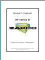
Owner's manual
ST-series D
Great Sound - Big Power - Compact Chassis
Before operating the unit, please read this manual throughly
and retain it for future reference.
Protect your
Investment
Note your information below for reference:
Model #
Serial #
Date Purchased
And: Register your Zapco product now
At:
www.zapco.com
Mission Statement
Committed to Excellence
Zapco is dedicated to the pursuit of audio fidelity. Our prime objectives are to design
and manufacture audio products of unsurpassed quality, to provide unparalleled support and
service for these products, and to conduct business in a manner that will enhance the quality of
life for all involved.
Experience: Knowledge from Doing
There is absolutely no substitute for experience; that is a simple fact of life. Another
simple fact is that Zapco has, for over forty years, been the leader in defining quality standards for
the car audio industry. These years of experience have led to a thorough understanding of the
challenges that are unique to the world of car audio. Zapco's relentless quest for sonic purity
consistently yields imaginative designs that utilize the most innovative technologies. The resulting
products set the criteria by which all others in the industry are judged.
The ST-Series D Full range Class D Amplifiers
Zapco introduced the industry to great sounding Class D amplifiers some 10 years ago
with the famous C2K-9.0XD. In those days, the filtering and control systems needed to make Zapco
sound quality in a Class D amplifier meant it had to be expensive and it had to be big.
Today's technology, however, has allowed us to develop a line of great sounding full
range Class D amps at an affordable price range and in a size that's an easy fit in today's smaller
cars. Small car doesn't have to mean small sound, and you won't have to give up the back seat for
an amplifier. And even motorcycles. In fact, at only 6.3" x 6.7", the ST2D is the ideal amplifier for a
motorcycle. Small size, big power. And talk about POWER! This tiny little monster is going to
give you 400watts RMS. With that kind of power on your bike, you're going to need louder pipes,
and, since these little power houses are Zapco amps, you know they're going to sound great.
Just like with the Z-Series and the ZX-Series, we kept the ST-D series simple. The feature
set is kept to the essentials. They all have 18dB crossovers, speaker level inputs, and optional
remote level controls, but, they don't have chrome or fancy paint jobs, and they don't look like
hot rod engines or computers. They look like car audio amplifiers. We put our efforts (and your
money) into great sound and reliable power.
Even though they're Class D they have less than 0.05% THD+noise and 90dB signal to
noise ratio. After all, loud is no good unless it sounds great as well. And these new amplifiers
sound awesome. Audition one today and you'll know what we mean.
And, though the 2ch, 4ch, and 5ch powerhouses have way more punch than you'd expect
from such a diminutive chassis, we know you're going to want dedicated bass amps as well. And the
ST-D series has 'em! You can choose 500 watts at 1 ohm or 1,000 watts at 1 ohm, and even the 1,000
watt amp is less than 10" long.
Power and Wire Gauge
The wire you use for the power and ground connections of your amplifier is
absolutely critical. The plain simple fact is that it takes power to deliver power. If
you do not provide the proper amount of 12V power to your amplifier, you will
never reach the full power potential of the amp. Take a look at the chart below.
If you want to have any respectable amount of power for your amp, you need a
4-gauge wire to the trunk as a bare minimum. If you are running any Zapco Z-series
amp in you trunk you need at least a 2 gauge wire. If you want enough
power to drive woofers, you’re certainly going to need at least a 2-gauge wire to
the rear and zero gauge is better.
Recommended Wire Gauge
Up to
20 A
35 A
50 A
60 A
85 A
105 A
125 A
150 A
4 Ft
14
12
10
8
4
4
4
2
7 Ft
12
10
8
8
4
4
4
2
10 Ft
12
8
8
4
4
4
4
2
13 Ft
10
8
4
4
4
2
2
2
16 Ft
10
4
4
4
2
2
2
0
19 Ft
8
4
4
4
2
2
0
0
22 Ft
8
4
4
4
2
2
0
0
28 Ft
8
4
4
2
0
0
0
0
You can certainly save money by buying cheap small gauge wire, but
remember...It will cost you in power and may even damage your car by passing
too much current and causing shorts or even fires. Protect your investment in
Zapco amplifiers by using high quality, proper gauge wire.
And remember... Current in the amplifier runs in a complete circuit from the
battery to the amp and back to the battery through the chassis and frame. The
ground wire us just as important as the power input wire. Positive and Negative
connections must always use the same gauge wire.
Installation Guidelines
Mounting your ST-Series Amplifier is easy. Keep in mind the following
guidelines:
The amplifier may be mounted in any direction, on wood, metal or carpet.
The metal case of the amplifier may be grounded or left isolated.
The amplifier requires adequate ventilation. Position the amplifier with
sufficient surrounding area for proper cooling. Keep fan and vent
endplates clear for proper internal cooling.
Keep the amplifier out of the engine compartment and other locations that
may cause excessive heat or moisture.
Make sure your ground point is at the frame or a chassis point with direct
frame contact. Note: the "quiet metal" on many new cars make body
panels very bad ground points, so always try to use the frame.
Do not mount the amplifier to a subwoofer enclosure or any other place
that may have excessive vibration!
-3-
Gain Setting
Matching Your Components for Best Sound
Proper gain setting is one of the most important factors in setting up a stereo
system. Unfortunately, gain setting is quite often done wrong. Turning up the
gain of an amp is the very last thing you should ever do to a system.
An amplifier is a step up transformer. Period. Any signal you put in is boosted by a
fixed factor, whether it's music, hiss, or any other noise. A large number of
noise problems are simply a matter of improper gain settings. The goal of gain
setting is to achieve the maximum amount of musical output from the amplifier
while getting the least amount of hiss or noise from the system. Your ST-Series
amplifier accepts an extremely wide range of input levels. As little as .5 volts
on the RCAs to as much as 8 volts. The basic gain setting is very simple and
requires no special tools. Whether you have a simple system with a deck and an
amp, or a system with a deck, line driver, equalizer, crossover, and amp, the
procedure is always the same. First, hook up the system with all gain controls at
minimum (turn the gain pot fully counter-clockwise with a small screwdriver).
Then turn on the head unit and turn up the volume. If you achieve clean sound,
and, more volume than you want, you don’t need to make any adjustments.
However, if you turn up the volume and begin to hear distorted sound before it
becomes loud, you are clipping (distorting) the deck (probably a little over ¾
volume). Turn the deck down just enough to hear clean sound again, and then
move to the next component in your system. With the deck playing at “maximum
clean volume” adjust the gain of the next component to its “maximum clean
volume”. If you adjust your gains this way, always starting at the head unit and
working down the line to the amplifier, you will get the most performance out of
your amplifier(s) with the least amount of unwanted distortion and noise.
Presenting
The Zapco Studio-D Series Amplifiers
-4-
FEATURES
ST-2D
High efficiency Class D amplifier
(efficiency : 80% @ 4 ohm, at 1kHz)
2/1 channel bridgeable car amplifier
Ultra low power consumption
Ultra compact heatsink
Stable into 4 ohms bridged or 2 ohms stereo load
PWM MOSFET power supply
Input sensitivity (gain) control variable
18dB octave crossover slope
Variable,selectable FULL / LP/ HP crossover
12 dB bass boost equalization control variable
Signal input and output RCA connectors
High level input connectors
Multi-way protection circuitry
(thermal / over current / speaker short / speaker DC protection)
Tested voltage & THD: 14.4V & less than 0.05% THD
Operating voltage : DC10V~15.5V power input
ST-4D
High efficiency Class D amplifier
(efficiency : 80% @ 4 ohm, at 1kHz)
4/3/2 channel bridgeable car amplifier
Ultra low power consumption
Ultra compact heatsink
Stable into 4 ohms bridged or 2 ohms stereo load
PWM MOSFET power supply
Input sensitivity (gain) control variable
18dB octave crossover slope
Variable, selectable FULL/ LP / HP crossover
2 dB bass boost equalization control variable
Signal input RCA connectors
High level input connectors
Multi-way protection circuitry
(thermal / over current / speaker short / speaker DC protection)
Tested voltage & THD: 14.4V & less than 0.05% THD
Operating voltage : DC10V~15.5V power input
-3-
FEATURES
ST-5D
High efficiency Class D amplifier
(efficiency : 80% @ 4 ohm, at 1kHz)
5/3 channel bridgeable car amplifier
Ultra low power consumption
Ultra compact heatsink
MOS-FET PWM power supply
4 ohm bridged or/and 2 ohm stereo load
18dB octave crossover slope
Variable low pass filter
Variable high pass filter
Variable subsonic filter
Signal input RCA connectors
High level input connectors
Multi-way protection circuitry
(thermal / over current / speaker short / speaker DC protection)
Tested voltage & THD: 14.4V & less than 0.05% THD
Operating voltage : DC10V~15.5V power input
ST-500DM
High efficiency Class D amplifier
(efficiency : 80% @ 4 ohm, at 1kHz)
Ultra low power consumption
Ultra compact heatsink
MOS-FET PWM power supply
High level input connectors
Multi-way protection circuitry
(thermal / over current / speaker short / speaker DC protection)
Tested voltage & THD: 14.4V & less than 0.1% THD
Operating voltage : DC10V~15.5V power input
Wired remote controller
ST-1KDM
High efficiency Class D amplifier
(efficiency : 80% @ 4 ohm, at 1kHz)
Ultra low power consumption
Ultra small sized heatsink
MOS-FET PWM power supply
High level input connectors
Multi-way protection circuitry
(thermal / over current / speaker short / speaker DC protection)
Tested voltage & THD: 14.4V & less than 0.1% THD
Operating voltage : DC10V~15.5V power input
Wired remote controller
-4-
RCA CONNECTION
ST-2D
OUTPUT
CH1
HI-INPUT
GAIN
FREQ
BASS
ST-2D
INPUT
CH1
+ - - +
CH1
CH2
MIN
MAX
50Hz
LPF
CH2
FULL
250Hz
0dB
12dB
HPF
CH2
to INPUT of
ADDITIONAL
AMPLIFIERS
HEAD UNIT
ST-4D
INPUT
CH1
CH3
HI-INPUT
GAIN
FREQ
BASS
ST-4D
CHANNEL 1/2
+ - - +
CH1
CH2
MIN
MAX
MIN
MAX
LPF FULL HPF
50Hz
250Hz
0dB
12dB
50Hz
250Hz
0dB
12dB
CH3- CH4
+
- +
CH2
CH4
HI-INPUT
GAIN
FREQ
CHANNEL 3/4
BASS
HEAD UNIT
Connect your source unit to the amplifier using the "INPUT" RCA connectors. The "OUTPUT" connector
can be used to pass the input signal to another amplier. For Initial Setup: Always set bass boost to 0dB,
and set the amplifier gain to minimum (8V sensitivity). Remember: amp gain is not a volume control.
It is used only to match your amplifier input sensitivity to your source unit output.
-5-
RCA CONNECTION
ST-5D
CHANNEL 5
CHANNEL 1/2
HI-INPUT
GAIN
HPF
SUBSONIC
LPF
INPUT
CH5A
ST-5D
INPUT
CH1
CH3
+ - - +
CH1
CH2
MIN
MAX
FULL HPF
50Hz
1KHz
10Hz
60Hz
CH3- CH4
+
- +
MIN
CH2
30Hz
250Hz
CH5A
+ - CH5B
- +
MAX
100Hz
2KHz
CHANNEL 3/4
CH4
MIN
MAX
GAIN
HI-INPUT
CH5B
HEAD UNIT
ST-500DM / ST-1KDM
HI-IN PUT
CH1/L
REMOTE
GAIN
+ - - +
CH1
CH2
Min
Max
CH2/R
Wired Remote Control
(optional)
HEAD UNIT
Connect your source unit to the amplifier using the "INPUT" RCA connectors.
Remember: amp gain is not a volume control.
It is used only to match your amplifier input sensitivity to your source unit output.
-6-
HIGH LEVEL INPUT CONNECTION
ST-2D
OUTPUT
CH1
HI-INPUT
GAIN
FREQ
BASS
ST-2D
INPUT
CH1
+ - - +
CH1
CH2
MIN
MAX
50Hz
LPF
CH2
FULL
250Hz
0dB
12dB
HPF
CH2
CH2+
HEAD UNIT
CH2 CH1 CH1+
from HEAD UNIT SPEAKER TERMINALS
ST-4D
INPUT
CH1
CH3
HI-INPUT
GAIN
FREQ
BASS
ST-4D
CHANNEL 1/2
+ - - +
CH1
CH2
MIN
MAX
MIN
MAX
LPF FULL HPF
50Hz
250Hz
0dB
12dB
50Hz
250Hz
0dB
12dB
CH3- CH4
+
- +
CH2
CH4
HI-INPUT
GAIN
FREQ
CHANNEL 3/4
BASS
HEAD UNIT
CH4+
CH2+
CH4 -
CH2 -
CH3 -
CH1 CH1+
CH3+
from HEAD UNIT SPEAKER TERMINALS
Caution
If the HIGH LEVEL INPUTS are used, do not use the LOW LEVEL RCA inputs at the same time.
-7-
HIGH LEVEL INPUT CONNECTION
ST-5D
CHANNEL 5
CHANNEL 1/2
HI-INPUT
GAIN
HPF
SUBSONIC
LPF
INPUT
CH5A
ST-5D
INPUT
CH1
CH3
+ - - +
CH1
CH2
MIN
MAX
FULL HPF
50Hz
1KHz
10Hz
60Hz
CH3- CH4
+
- +
MIN
CH2
30Hz
250Hz
CH5A
+ - CH5B
- +
MAX
100Hz
2KHz
CHANNEL 3/4
CH4
HEAD UNIT
MIN
MAX
GAIN
HI-INPUT
CH5B
CH5A+
CH5ACH5BCH5B+
CH4+
CH2+
CH4 -
CH2 -
CH3 -
CH1 CH1+
CH3+
from HEAD UNIT SPEAKER TERMINALS
ST-500DM / ST-1KDM
HI-IN PUT
CH1/L
REMOTE
GAIN
+ - - +
CH1
CH2
Min
Max
CH2/R
CH2+
HEAD UNIT
CH2 CH1 CH1+
from HEAD UNIT SPEAKER TERMINALS
Caution
If the HIGH LEVEL INPUTS are used, do not use the LOW LEVEL RCA inputs at the same time.
-8-
POWER CONNECTION
ST-2D / ST-4D / ST-5D / ST-500DM/ ST-1KDM
GND
REM
B+
POWER INPUT
GROUND
Caution
This amplifier is not supplied with internal
fuse in itself. Make sure you install in-line
fuse holder from the +terminal of battery.
Recommend 70 Ampere fuse.(ST-2D)
Recommend 100 Ampere fuse.(ST-4D)
Recommend 150 Ampere fuse.(ST-5D)
Recommend 100 Ampere fuse.(ST-500DM)
Recommend 200 Ampere fuse.(ST-1KDM)
to REMOTE Turn-on
from HEAD UNIT
HEAD UNIT
BATTERY
GROUND
+12V Power
Disconnect the Battery ground. Connect the +12V terminal of the amplifier to the + terminal of
the battery using the appropriate guage wire cable. Always use the same guage wire for Power
and Ground. Install an in-line fuse holder, within approximately 14" of the + terminal of battery.
GROUND
Connect the GND (ground) terminal to the cars frame of chassis.
Keep this cable as short as possible and make sure that the connection with the frame or chassis is rust
free and clear of paint or grime. Any ground connection should be at the frame or a part with direct
connection to a major frame component.
REMOTE
Connect the REM terminal of the amplifier to the 12v trigger output of the source unit or a car accessory
terminal at the fuse box or ignition switch using appropriate gauge wire.
Caution
After all electrical connections are made: You may re-connect the battery ground.
Always use recommended fuse ratings. Wire must always be fused at the battery for protection
against possible damage to the vehicle. If you need to replace the power fuse, replace it with
a fuse of the same value.
-9-
SPEAKER CONNECTION
ST-2D
1 Channel Bridged
CH1/2 BRIDGED
GND
REM
B+
PWR
CH1
CH2
CH1-MONO
SUBWOOFER
PRT
SPEAKER OUTPUTS
POWER INPUT
Speaker Impedance
4~8 ohms
2 Channel Stereo
CH1/2 BRIDGED
GND
REM
B+
PWR
CH1
CH2
CH2
PRT
POWER INPUT
Speaker Impedance
2~8 ohms
SPEAKER OUTPUTS
CH1
3 Channel Tri Mode
CH1/2 BRIDGED
GND
REM
B+
PWR
CH1
CH2
CH2
PRT
POWER INPUT
SPEAKER OUTPUTS
Speaker Impedance
4~8 ohms
X-O
CH1
X-O
X-O
Note: All Tri-Mode woofer setups
require crossovers between Woofers
and Mids-Highs to preserve minimum
impedance for amplifier stability.
CH3-MONO
SUBWOOFER
-10-
Speaker Impedance
4~8 ohms
SPEAKER CONNECTION
ST-4D
2 Channel Bridged
CH1
GND
REM
B+
PWR
CH1
CH3
CH2
CH4
Speaker Impedance
4~8 ohms
CH1/2 BRIDGED
PRT
CH1
CH2
CH3
CH4
CH3/4 BRIDGED
SPEAKER
POWER INPUT
CH2
4 Channel Stereo
CH2
CH1
GND
REM
B+
PWR
CH1
CH3
CH2
CH4
CH1/2 BRIDGED
PRT
CH1
CH2
CH3
CH4
Speaker Impedance
2~8 ohms
CH3/4 BRIDGED
SPEAKER
POWER INPUT
CH3
CH4
6 Channel Tri Mode
Hook-up with required crossovers
X-O
CH5-MONO
SUBWOOFER
X-O
CH2
X-O
CH1
GND
REM
B+
PWR
PRT
CH1
CH3
CH2
CH4
Speaker Impedance
4~8 ohms
CH1/2 BRIDGED
CH1
CH2
CH3
CH4
CH3/4 BRIDGED
POWER INPUT
SPEAKER
CH3
CH4
X-O
CH6-MONO
SUBWOOFER
X-O
X-O
-11-
SPEAKER CONNECTION
ST-5D
5 Channel Mode
GND
REM
B+
PWR
CH5
CH5
CH3/4 BRIDGED
CH1/2 BRIDGED
CH4
CH4
CH2
CH2
CH3
CH3
CH1
CH1
CH1
CH2
PRT
SPEAKER
POWER INPUT
Speaker Impedance
2~8 ohms
CH3
CH4
CH5
SUB WOOFER
Bridge Mode
GND
REM
B+
PWR
CH5
CH5
CH3/4 BRIDGED
CH1/2 BRIDGED
CH4
CH4
CH2
CH2
CH3
CH3
CH1/2Full Range
CH1
CH1
PRT
POWER INPUT
Speaker Impedance
4~8 ohms
SPEAKER
CH3/4 Full Range
CH5
SUB WOOFER
-12-
SPEAKER CONNECTION
ST-5D
5 Channel Mode
Hook-up with required crossovers
X-O
GND
REM
B+
PWR
CH5
CH5
CH3/4 BRIDGED
CH1/2 BRIDGED
CH4
CH4
CH2
CH2
CH3
CH3
CH1
CH1
CH1/2
BRIDGED
PRT
POWER INPUT
SPEAKER
X-O
X-O
CH1
CH2
Speaker Impedance
4~8 ohms
X-O
X-O
CH3
CH4
CH3/4
BRIDGED
X-O
Note: All Tri-Mode woofer setups
require crossovers between Woofers
and Mids-Highs to preserve minimum
impedance for amplifier stability.
CH5
SUB WOOFER
-13-
SPEAKER CONNECTION
ST-500DM / ST-1KDM
1. Single Voice
4 Ohm Load
GND
REM
B+
SPK A
PWR
2 Ohm Load
GND
SPK B
REM
B+
SPK B
PRT
SPEAKER OUTPUTS
POWER INPUT
SPEAKER OUTPUTS
POWER INPUT
-
+
(4
SPK A
PWR
PRT
SUBWOOFER
Single Voice Coil)
GND
-
+
REM
(4
1 Ohm Load
B+
PWR
SPK A
-
+
SUBWOOFER x 2
Single Voice Coil)
SPK B
PRT
POWER INPUT
-
+
-
+
SPEAKER OUTPUTS
(4
-
+
-
+
SUBWOOFER x 4
Single Voice Coil)
2. Dual Voice
2 Ohm Load
GND
REM
B+
PWR
SPK A
SPK B
1 Ohm Load
GND
B+
REM
PWR
PRT
POWER INPUT
SPK B
PRT
SPEAKER OUTPUTS
+ -
POWER INPUT
SPEAKER OUTPUTS
- +
+ -
(4
SPK A
SUBWOOFER
Dual Voice Coil)
- +
+ -
- +
2
(4
2
SUBWOOFER
Dual Voice Coil)
(4
SUBWOOFER
Dual Voice Coil)
Caution
These amplifiers can not be "strapped" with another amp. If you use this
amplifier in "Strapped" mode, damage may occur.
Use the amplifier in MONO mode only in compliance with above shown pictures.
-14-
SPECIFICATIONS
ST-2D
Rated power output
-RMS power, 4 ohms stereo ------- 100W x 2CH
-RMS power, 2 ohms stereo ------- 200W x 2CH
-RMS power, 4 ohms bridged ------ 400W x 1CH
Signal to Noise Ratio ------------------ >90dB
Low Pass Crossover ------------------- 30Hz ~ 250Hz
High Pass Crossover ------------------- 50Hz ~ 500Hz
Bass boost @ 45Hz -------------------- Variable 0~12dB
Frequency Response ------------------- 10Hz ~ 30KHz (+/-1dB)
T.H.D @ 4 ohms ---------------------- < 0.05%
Channel Separation ------------------- 60dB
Fuse Rating ---------------------------- 70A(external type fuse)
Input Sensitivity (low input) -------- 200mV~8V (+/- 5%)
(high input) ------ 2V~10V (+/- 5%)
170(W) x 52(H) x 160(L)7
Dimensions(mm) --------------------- 1
ST-4D
100W x 4CH
200W x 4CH
340W x 2CH
>90dB
50Hz ~ 500Hz
30Hz ~ 250Hz
Variable 0~12dB
10Hz ~ 30KHz (+/-1dB)
< 0.05%
60dB
100A(external type fuse)
200mV~8V (+/- 5%)
2V~10V (+/- 5%)
170(W) x 52(H) x 210(L)
ST-5D
Rated power output
-RMS power, 4 ohms stereo -------------------------------------------- 80W x 4CH + 225W x 1CH
-RMS power, 2 ohms stereo -------------------------------------------- 150W x 4CH + 380W x 1CH
-RMS power, 4 ohms bridged ------------------------------------------ 300 w x 2CH + 380W x 1CH
Signal to Noise Ratio ----------------------------------------------------- >90dB
Low Pass Crossover ------------------------------------------------------- 30Hz ~ 300Hz
High Pass Crossover ------------------------------------------------------- 50Hz ~ 1KHz(CH1/4)
------------------------------------------------------- 10Hz ~ 2KHz(CH3/4)
Subsonic filter -------------------------------------------------------------- 10Hz ~ 250Hz
Frequency Response ------------------------------------------------------ 10Hz ~ 30KHz (+/-1dB)
T.H.D @ 4 ohms ----------------------------------------------------------- < 0.05%
Channel Separation ------------------------------------------------------- 60dB
Fuse Rating --------------------------------------------------------------- 150A(external type fuse)
Input Sensitivity (low input) -------------------------------------------- 200mV~8V (+/- 5%)
(high input) ------------------------------------------ 2V~10V (+/- 5%)
Dimensions(mm) --------------------------------------------------------- 170(W) x 51(H) x 270(L)
ST-500DM
Rated power output
-RMS power, 4 ohm mono --------- 200W x 1CH
-RMS power, 2 ohm mono --------- 370W x 1CH
-RMS power, 1 ohm mono --------- 500W x 1CH
Signal to Noise Ratio ----------------- > 90dB
Frequency response-------------------- 10Hz~350Hz (+/- 1dB)
T.H.D @ 4 ohms ----------------------- < 0.1%
Efficiency @ 4 ohm--------------------- 82%
Fuse rating------------------------------ 100A(external type fuse)
nput Sensitivity (low input) --------- 200mV~8V (+/- 5%)
(high input) -------- 2V~10V (+/- 5%)
Dimensions(mm) --------------------- 170(W) x 52(H) x 190(L)
ST-1KDM
360W x 1CH
700W x 1CH
1000W x 1CH
> 90dB
10Hz~350Hz (+/- 1dB)
< 0.1%
82%
200A(external type fuse)
200mV~8V (+/- 5%)
2V~10V (+/- 5%)
170(W) x 52(H) x 250(L)
The above specifications shall be modified by manufacturer for improvement without prior notice.
-15-
TROUBLE SHOOTING GUIDE
This power amplifier has protection features to prevent most forms of damage.
If the unit senses excessive heat, short circuited speakers or overload, the protection indicators will
be lit and the system will be turned off. Prior to checking the wiring for any fault, you should turn all
level controls down and turn off power. If the amplifier shuts down due to excessive heat, the
protection indicators will not be lit: simply allow the amplifier to cool down.
Before removing your amplifier, refer to the list below and follow the suggested procedures.
Always test the speakers and their wires first.
AMPLIFIER IS NOT POWERED UP
Check
Check
Check
Check
if
if
if
if
at least +12V DC is present on the battery power terminal.
at least +12V DC is present on the remote terminal.
a good ground connection is present. Check all fuses.
the protection LED is not lit.
PROTECTION LED ILLUMINATES WHEN AMPLIFIER IS POWERED UP
Check to see if any speaker wires are short-circuited to the chassis or themselves.
Remove speaker wires and reset the amplifier. If the protection LED still comes on,
then the amplifier is at fault.
FUSE BLOWING
Check if the minimum speaker impedance is met.
Check for short-circuits on power cable and vehicle chassis.
OVERHEATING
Check if the minimum speaker impedance is met.
Check speakers for short-circuits.
Check if there is good airflow around the amplifier
SOUND TOO LOW-DISTORTED SOUND
Check
Check
Check
Check
if the input level control is set to match the output level of the source unit.
the head unit's volume.
speakers for short-circuits
if crossover frequencies have been properly set.
HIGH HISSING NOISE - ENGINE NOISE IN SPEAKERS
Check if a good ground connection is present. Most engine noises are caused by
grounding issues.
Hissing noise is most often caused by gain issues. Proper gain matching is
usually required to eliminate hissing noise.
-16-
Technical Assistance
Should you experience a problem with your DSP6-SL or DRC-SL, please contact the
dealer that sold you this product. If your dealer is unable to solve your problem, you
may contact the factory service department directly.
Phone: (209) 577-4268 Monday - Friday, 8AM - 5PM Pacific Standard Time FAX: (209)
577-8548
Also, check our web page, www.zapco.com, for tips. You can also e-mail for technical
help directly from our web page.
If you need to return this product for repair, please call the factory for a Return Materials
Authorization (RMA) number. We will ask you for information that will include your name,
return shipping address, daytime phone number, model and serial number, and a detailed
description of your problem. A photocopy of your original purchase receipt is necessary
to determine warranty status and should also be included. Once we issue you an RMA,
please write it in a highly visible area on the package. ZAPCO will not accept any
packages that do not have a valid RMA number clearly marked on the outside of the
package.
Once you have a valid RMA number, send all repairs to:
A.R.P.A. of America Corp. / Zapco
Attn.: Service Department
3037 E Palm Ave Suite 102, Manteca, CA 95337
-17-
ARPA of America Corporation
3037 E Palm Ave Suite 102
Manteca, CA 95337
Phone: (800) 47-Force
The Zapco DC-Series is a joint venture of ARPA of America
and ARPA Italy and manufactured in Korea