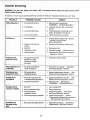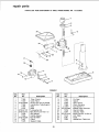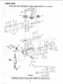
1
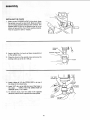
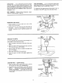
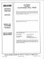
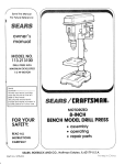
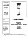
SAVE THIS MANUAL
FOR FUTURE REFERENCE
MODEL NO.
113.213853
DRILL PRESS WiTH
1/2 HP MOTOR
Serial
Number
®
Model and serial number
may be found at the rear of
the head.
You should record both
model and serial number in
a safe place for future use.
MOTORIZED
15 INCH
FLOOR MODEL DRILL
• assembly
• operating
e repair parts
CAUTION:
Read GENERAL
and ADDITIONAL
SAFETY
INSTRUCTIONS
carefully
Sold
PART NO. SP4964
by SEARS,
PRESS
ROEBUCK
AND
CO.,
Chicago,
IL. 60684
U.S.A.
PRINTED
IN USA.
FULL ONE YEAR WARRANTY
OhL
CRAFTSMAN
DRILL PRESS
If within one year from the date of purchase, this Cra_sman Drill Press fails due to a defect
in material or workmanship, Sears will repair it, free of charge.
WARRANTY SERVICE IS AVAILABLE BY SIMPLy
CONTACTING THE NEAREST SEARS
SERVICE CENTER/DEPARTMENT THROUGHOUT
THE UNITED STATES.
THIS WARRANTY APPLIES ONLY WHILE THIS PRODUCT
This warranty gives you specific legal rights,
vary from state to state.
and
SEARS, ROEBUCK AND CO., Dept. 698/731
iS iN USE iN THE UNITED STATES.
you may also have other rights which
A, Sears Tower, Chicago, IL 60684
i
general safety instructions for
1. KNOW YOUR POWER TOOL
Read and understand the owner's manual and
labels affixed to the tool. Learn its application and
limitations as well as the specific potential hazards
peculiar to this tool.
1 2. USE SAFETY
GOGGLES
(Head Protection)
Wear
Safety goggles (must comply with ANSI
Z87.1 } at ati times. Everyday eyeglasses only have
impact resistant lenses, they are NOT safety glasses. Also. use face or dust mask if cutting operation
is dusty, and ear protectors (plugs or muffs) during
extended
periods of operat=on,
2. GROUND ALL TOOLS
This tool is equipped with an approved 3-conductor
cord and a 3-prong grounding type plug to fit the
proper grounding type receptacle. The green conductor in the cord is the grounding wire. Never
connect the green wire to a live terminal.
3. KEEP GUARDS IN PLACE
In working order, and in proper adjustment
power tools
13,
SECURE WORK
Use clamps or a vise to hold work when practical.
It's safer than us=ng your hand, frees both hands
to operate toot.
1 4. DON'T
an(;
Keep
alignment.
4. REMOVE ADJUSTING KEYS AND
WRENCHES
....
Form a habit of checking to see that keys and
adjusting wrenches are removed from tool before
turning it on.
15.
16,
5. KEEP WORK AREA CLEAN
Cluttered areas and benches invite accidents.
Floor must not be slippery due to wax or sawdust.
17.
6. AVOID DANGEROUS ENVIRONMENT
Don't use power tools in damp or wet locations or
expose them to rain, Keep work area well lighted,
Provide adequate surrounding work space.
7. KEEP CHILDREN AWAY
All visitors should be kept a safe distance from
work area.
18.
19.
8. MAKE WORKSHOP KID-PROOF
--with padlocks, master switches, or by removing
starter keys.
OVERREACH
proper footing and balance
at all times,
MAINTAIN
TOOLS WITH CARE
Keep tools sharp and clean for best and safest
performance,
Follow instructions for lubricating and
changing
accessor=es.
DISCONNECT
TOOLS
Before servicing
when changing
as blades, bits. cutters, etc.
accessories
AVOID ACCIDENTAL
STARTING
Make sure switch is in "OFF" position
ging in.
before
such
plug-
USE RECOMMENDED
ACCESSORIES
Consult the owner's manual for recommended
accessories. Foltow the instructions that accompany
the accessories.
The use of improper accessories
may cause hazards,
NEVER STAND ON TOOL
Serious injury could occur if the tool is tipped
the cutting toot is accidentally
contacted.
or if
Do not store materials above or near the tool such
that it _s necessary to stand on the tool to reach
them,
9. DON'T FORCE TOOL
It will do the job better and safer at the rate for
which it was designed.
10. USE RIGHT TOOL
Don't force tool or attachment to do a job it was
not designed for,
11. WEAR PROPER APPAREL
Do not wear loose clothing, gloves, neckties or
jewelry (rings, wrist watches) to get caught in moving parts, Nonslip footwear is recommended. Wear
protective hair covering to contain long hair. Rol!
long sleeves above the elbow.
20.
CHECK
DAMAGED PARTS
Before further use of the tool. a guard or other part
that is damaged should be carefully checked to
ensure that it will operate properly and perform its
intended function. Check for alignment of moving
parts, binding of moving parts, breakage of parts,
mounting, and any other conditions that may affect
its operation, A guard or other part that is dam agecl
should be properly repaired or replaced.
2
21. DiRECTiON OF FEED
22.
Feed work into a blade or cutter against the direction of rotation of the blade or cutter only.
additional
safety instructions
for drill presses
c. To avoid injury from parts thrown
by the spring,
follow instructions
exactly
as given and shown
in adjusting spring tension
of quilt.
d. To prevent the workpiece
from being torn from
your hands, spinning of the toot, shattering the
too! or being thrown, always
properly
support
your work so it won't shift or bind on the tool:
-- Always position BACKUP
MATERIAL
(use
beneath the workpiece)
to contact the left
side of the column.
-- Whenever
possible,
position
the WORKPIECE to contact the left side of the column
- if it is too short or the table is tilted, clamp
solidly to the table. Use table slots or clamping ledge around the outside
edge of the
table.
-- A drill press VICE must always be fastened
to the table.
-- Never
perform
any
operation
"FREEHAND"
(hand-holding
workpiece
rather
than supporting
it on
the table), except
when polishing.
-- Securely lock Head and Supportto
Column,
Table Arm to support,
and Table to Table
Arm before operating
drill press.
-- Never move the Head
or Table while the
tool is running.
-- Before starting the operation,
jog the motor
switch to make sure the drill or other cutting
tool does not have excessive
runout (wobble) or cause vibration.
-- If a workpiece
overhangs
the table such
that it will fall or tip if not held, clamp it to
the table or provide auxiliary
support.
-- Use fixtures
for unusual
operations
to
adequately
hold, guide
and position workpiece.
-- Use the SPINDLE
SPEED
recommended
for the specific operation
and workpiece
material - check the panel
on the left side
of the head for dri!ting
information;
for accessories, refer to the instructions
provided
with the accessories.
WARNUNG: For your own safety, do not attempt to
operate your drill press until it is completely assembled and installed according
to the instructions
. . . and until you have read and understand the
following:
Page
1. Genera0 Safety mnstructions for Power Tools. 2
2. Getting to Know Your Drill Press ........
12
3. Basic Drill Press Operation
.............
15
4. Adjustments ..........................
5. Maintenance ..........................
17
18
6. Stability of Drill Press
If there is any tendency
of the drill press to tilt or
move during certain operations,
the drill press
should be bolted to the floor. An alternate is to
securely bolt a flat piece of W' exterior plywood
large enough to stabilize the drill press to tile underside of the Base, extending
to both sides, and to
rear if desired. Make sure the plywood won't trip
the operator. Do not use pressed wood panels they can break unexpectedly.
If the workpiece
is too large to support
hand, provide an auxiliary support.
7.
NEVER LEAVE TOOL RUNII_,,IING UNATTENDED
Turn power off. Don't leave tool unti! it comes to a
comptete stop.
with one
Location
The drill press should be positioned
so neither the
operator nor a casual observer
is forced to stand
in line with a potential Kickback, in a poorly lit area
or where the surface could cause trips, slips or falls.
8. Kickback
A kickback occurs when the workpiece is suddenly
thrown in the OPPOSITE direction to the DIRECTION OF FEED; THIS CAN CAUSE SERIOUS INJURY. Kickbacks are most commonly caused by
use of accessories NOT listed on page 21.
9. Protection: Eyes, Hands, Face, Ears and Body
WARNING: To avoid being pulled into the spinning tool -1. Do NOT wear:
- gloves
- necktie
- loose clothing
- jewelry
2. Tie back long hair
f. Never ictimb on the drill press Table, it could
break or pul! the entire drill press down on you.
g, Turn the motor Switch Off and put away the
Switch Key when leaving the drill press.
h. To avoid injury from thrown work or too! contact,
do NOT perform layout, assembly, or setup work
on the table while the cutting tool is rotating.
a. If any part of your drill press is missing, malfunctioning, has been damaged or broken..,
such
as the motor switch, or other operating control,
a safety device or the power cord..,
cease
operating immediately until the particular part is
properly repaired or replaced.
b. Never place your fingers in a position where
they could contact the drill or other cutting too!
if the workpiece should unexpectedly shift or
your hand should slip.
10, Use only accessories designed
for this drill
press to avoid serious injury from thrown broken parts or work pieces.
a. Holesaws must NEVER be operated on this drill
press at a speed greater than 400 RPM.
b. Drum sanders must NEVER be operated on this
drill press at a speed greater than 1800 RPM.
3
add it.......
mona!safety mnstrucuons Tot ar il"! presses
c. Do not install or use any drill that exceeds 7" in
length or extends 6" below the chuck jaws. They
can suddenly bend outward or break,
13, Think Safety. Safety is a combination of operator
common sense and alertness at all times when the
drill press is being used.
d. Do not usewire wheels, router bits. shaper cutters, circle (fly) cutters or rotary planers on this
drill press.
WARNING: Do not allow familiarity
(gained from
frequent use of your drill press) to become commonplace. Always remember that a careless fraction of a second is sufficient to inflict severe injury,
11. Note and Follow the Safety Warnings and Instructions that Appear on the Panel on the Left
Side of the Head:
The operation of any power tool can result in foreign
objects being thrown into the eyes, which can result =n
severe eye damage. Always wear safety goggles complying with ANSI Z87.1 (shown on Package) before
commencing power too! operation. Safety Goggles are
available at Sears retail or catalog stores.
J DANGER ]
FOR YOUR OWN SAFETY:
1. READ AND UNDERSTAND OWNERS MANUAL BEFORE OPERATING MACHINE.
2. WEAR SAFETY GOGGLES.
3. DO NOT WEAR GLOVES, NECKTIE, OR
LOOSE CLOTHING. TiE BACK LONG HAIR.
4. SECURELY CLAMP WORK TO TABLE IF IT
IS TOO SHORT TO CONTACT THE COLUMN
WHEN IN OPERATING POSITION
5. USE RECOMMENDED SPEED FOR DRILL,
ACCESSORY, AND WORKPIECE MATERiAL.
6. SECURELY LOCK HEAD AND SUPPORT TO
COLUMN, ARM TO SUPPORT, AND TABLE
TO ARM
BEFORE OPERATING
DRILL
PRESS.
7. USE
ONLY
RECOMMENDED
ACCESSERIES.
12, This Drill Press has 12 speeds as listed below:
300 RPM
1450 RPM
375 RPM
1530 RPrvl
525 RPM
2000 RPM
560 RPM
2200 RPM
700 RPM
3400 RPM
860 RPM
4600 RPM
See right side of Head for specific placement of
belt on pulleys.
unpacking and checking contents
CONTENTS
PAGE
General Safety Instructions for Power Tools ......
2
Additional Safety Instructions for Drill Presses .... 3
Unpacking and Checking Contents .............
4
Table of Loose Parts ........................
5
Motor Specifications and Electrical
Requirements ..............................
6
Assembly .................................
7
Assembly of Column and Table Hardware .... 7
Installing the Table ......................
7
installing the Head .......................
Tensioning Belt .........................
9
Installing Upper Belt Guard ...............
10
Installing Feed and Tension Handles .......
11
Installing the Chuck .....................
12
Installing Light Bulb .....................
13
Adjusting the Table Square to Head .......
13
Adjusting the Pointer ....................
13
CONTENTS
Getting to Know Your Drill Press ..............
Removing the Chuck ....................
Drilling to Depth .......................
Depth Scale ...........................
Basic Drill Press Operation ..................
Installing Drills .........................
Positioning Table and Workpiece ..........
Tilting Table ...........................
Hole Location .........................
Feeding .............................
Adjustments ..............................
Quill Return Spring .....................
Maintenance ..............................
Lubrication ...............................
Recommended Accessories ..................
Trouble Shooting ..........................
Repair Parts ..............................
4
PAGE
14
17
17
17
18
18
19
19
20
20
20
20
21
21
21
22
23
UNPACKING
AND CHECKaNG
CONTENTS
TOOLS
NEEDED
Model No. 113.213853 is shipped complete in one carton and includes a 1/2 HP 1725 RPM motor.
COMBiNAT_
Separate all parts from packing materials and check
each one with the "Table of Loose Parts" to make certain
all items are accounted for, before discarding any packing material.
WARNING:
missing, do
plug in the
the missing
rectly.
COMBINATION
DRAW
MEDIUM
SCREWDRIVER
Apply a coat of paste wax to the table to prevent rust.
Wipe all parts thoroughly with a clean dry cloth.
item
A
B
C
D
E
F
G
H
1/2 WRENCH
PARTS
Description
Column Assembly ......................
Upper Guard ..........................
Head Assembly ........................
Table ................................
Base .................................
Owners manual ........................
Motor ......
_ .........................
Box Of Small Parts .....................
Part #507377
(Containing the Following Items)
Handle, Feed ..........................
Crank, Table ..........................
Handle, Belt Tension ...................
Clamp, Bolt ...........................
Key, Chuck ...........................
Chuck ................................
Bag of Loose Parts No. 507375 ...........
Bag of Loose Parts No. 507375
(Containing the Following Items)
Indicator Table Support ..................
Screw Pan Hd. 10-32xl/4 ................
Screw Hex Hd. 3/8-16xl 1/2 ..............
Lockwasher 3/8 ........................
Key, Switch ...........................
Screw Soc. Set 3/8-16xl/2 ................
Knob ................................
Screw Pan Hd. 1/4-20xl/2
...............
Screw Pan Hd. 8-32xl/2 .................
Lockwasher #8 ........................
Nut Hex 8-32 ........................
Bag of Loose Parts No.507440
(Containing the Following Items)
Pulley, Center ........................
Pulley, Motor ..........................
._
OF
PERFECTLY
STRAIGHT
SHOULD BE NO GAP OR OVERLAP WHEN
SQUARE IS FLIPPED OVER IN DOTTED POSITION
WARNING: To avoid fire or toxic reaction, never
use gasoline, naptha or similar highly volatile sol=
vents.
OF LOOSE
_
EDGE
BOARD 3!4" THICK
, THIS EDGE MUST BE
_
Remove the protective oil that is applied to the table
and column. Use any ordinary household type grease
and spot remover.
TABLES
MUST BE TRUE
STRAIGHT
LINE ON BOARD
ALONG THIS EDGE,_
For your own safety: if any parts are
not attempt to assemble the drill press,
power cord or turn the switch on until
parts are obtained and installed cor-
SQUARE
LIGHT
8-iNCH
ADJUSTABLE
WRENCH
118"- 3/16"
HEX "L" WRENCH
A
Qty.
1
1
1
1
1
1
1
1
3
1
. t
1
1
1
1
1
1
4
4
1
2
1
1
3
3
:.3
Screw Soc. Set 1/4-20x3/8 ...............
Belt "V" 3/8x24 .........................
Belt "V" 3/8x27 .........................
Screw Hex Hd. 5/16-18x3/4 ..............
Washer 21/64x !/2x 1/32 ..................
Nut Hex 5/16-18 .......................
:. 1
1
5
1
!
t
4
8
4
"
"
r equirements
motor specifications
and emectrmcaa
MOTOR SPECIFICATIONS
This power tool Is equipped with a 3-conductor cord
This drill press is designed to use a 1725 RPM motor
only. Do not use any motor that runs faster than 1725
RPM. It is wired for operation on 110-120 volts, 60 Hz.
alternating current,
and grounding type plug which has a grounding prong,
approved by Underwriters' Laboratories and the Canadian Standards Association.The ground conductor has
a green jacket and is attached to the tool housing at
one end and to the ground prong =nthe attachment
plug at the other end.
WARNING: To avoid injury from unexpected startup, do not use blower or washing machine motors
or any motor with an automatic reset overload protector.
CONNECTING TO POWER SOURCE OUTLET
This machine must be grounded while in use to protect
the operator from electric shock.
Plug power cord into a 110-120V properly grounded
type outlet protected by a 15-amp. dual element time
delay or Circuit-Saver fuse or circuit breaker.
NOT ALL OUTLETS ARE PROPERLY GROUNDED.
IF YOU ARE NOT SURE THAT YOUR OUTLET, AS
PICTURED BELOW, IS PROPERLY GROUNDED,
HAVE IT CHECKED BY A QUALIFIED ELECTRICIAN.
WARNING: Do not permit fingers to touch the terminals of plugs when installing or removing the
plug to or from the outlet.
WARNING: If not properly grounded this power
tool can incur the potential hazard of electrical
shock, particularly when used in damp locations,
in proximity to plumbing. If an electrical shock occurs there is the potential of a secondary hazard
such as your hands contacting the cutting tool.
This plug requires a mating 3-conductor grounded type
outlet as shown,
If the outlet you are planning to use for this power tool
is of the two prong type, DO NOT REMOVE OR ALTER
THE GROUNDING PRONG IN ANY MANNER. Use
an adapter as shown and always connect the grounding
lug to known grown.
It is recommended that you have a qualified electrician
replace the TWO prong outlet with a properly grounded
THREE prong outlet.
An adapter as shown below Js available for connecting
plugs to 2-prong receptacles.
WARNING: The green grounding lug extending
from the adapter must be connected to a permanent
ground such as to a properly grounded outlet box.
GROUNDING
LUG
\
SCR_,,_
3-PRONG
PLU
MAKE SURE THIS IS
CONNECTED TO A
KNOWN GROUND
If power cord is worn or cut, or damaged in any
way, have it replaced immediately to avoid shock
or fire hazard.
2-PRONG
RECEPTACLE
3.PRONG
PLUG
\
ADAPTER
NOTE: The adapter illustrated is for use only if you
already have a properly grounded 2-prong receptacle.
Adapter is not allowed in Canada by the Canadian Electrical Code,
GROUNDING
PRONG
ALWAYS USE A
PROPERLY GROUNDED
OUTLET
If your unit is for use on less than 150 volts, it has a
plug that looks like the above.
The use of any extension cord wilt cause some loss of
power. To keep this to a minimum and to prevent overheating and motor burn-out, use the table below to
determine the minimum wire size (A.W.G.) extension
cord. Use only 3 wire extension cords which have 3prong grounding type plugs and 3-pole and 3-pole receptacles which accept the tools plug.
ExtensionCordLength
Upto-lOOFt.
100-200 R.
200-400 R.
WireSizeA.W.G.
16
14
10
assembly
WARNING: For your own safety, never connect
plug to power source outlet until all assembly steps
are completed.
COLUMN
I
s
ASSEMBLY OF COLUMN AND TABLE HARDWARE
1. Position base on floor. Remove protective covering
and discard.
2. Remove protective sleeve from column tube and
discard. Place column assembly on base, and align
holes in column support with holes in base.
3. Locate four (4) 3/8-16xl 1/2 bolts and four (4) 3/8
Iockwashers among loose parts bag.
4. Install a Iockwasher and bolt in each hole through
column support and base, and tighten with adjustable wrench.
TABLE
SUPPORT
COLUMN
5. Locate table crank assembly,
wrench among loose parts.
support
lock, and
TABLE
SUPPORT
6. Install table crank assembly and tighten set screw
with 1/8" HEX "L" wrench.
7. Install support lock from left side into table support
and tighten by hand.
8. Handle should turn freely when raising or lowering
table, if adjustment is needed, loosen jam nut, with
a screwdriver loosen bolt handle until there is play
between jam nut and handle. Tighten jam nut securely while holding bolt handle with screwdriver.
JAM
SUPPORT
LOCK
NUT
HANDLE
TABLE
CRANK
COLUMN
9. Position column collar over rack and tighten set
screw in collar, with 1/8" HEX "L" wrench. Collar
should not be angled on the column. Only tighten
set screw enough to keep collar in place; rack should
still slide freely in collar.
CAUTION: To avoid column or collar damage,
do not overtighten set screw.
COLUMN
COLLAR
RACK
COLI
TABLE
SUPP_
INSTALLING THE TABLE
1. Loosen support lock and raise table support by turning table crank clockwise until support is at a working
height level. Tighten support lock.
SUPPORT
LOCK
7
RACK
assembly
TABLE
LOCK
2. Remove protective covering from table and discard.
Place table in table support and tighten table lock
(located under table) by hand.
/
TABLE
TABLE
SUPPORT
iNSTALLING
/
THE HEAD
CAUTION: The head assembly
pounds. Carefully lift head.
weighs about 55
HEAD
1. Remove protective bag from head assembly and
discard. Carefully lift head above column tube and
slide it onto column into position. Align head with
table and base.
HEAD
LOCKS
2. Locate two (2)3/8-16xl/2
parts bag.
set screws among loose
3. Install set screws m right side of head to lock head
into position, and tighten with 3/16" HEX "L" wrench.
HEAD
MOTOR
BRACKET
MOUNTING MOTOR
1. Locate four (4) 5/16-18x3/4 hex head bolts, eight
(8) flat washers, and four (4) hex nuts amoung loose
parts.
MOTORBASE
2. Install hex head bolts through motor bracket on
head.
3. Place motor in position so motor base slots line up
with motor brackets slots. Install flat washers and
hex nuts as illustrated.
4. Motor shaft should be in center of slot in lower guard.
5/16 HEX
HEAD NUT
8
FLAT
WASHER
5/16-18
HEXHEAD
BOLTS
MOTOR PULLEY
INSTALLING
MOTOR PULLEY
SET SCREW ___
1. Loosen set screw in motor pulley using 1/8" HEX
"L" wrench,
FLAT SURFACE
2, Slide pulley onto motor shaft. Line up the flat surface
on the motor shaft with the set screw in pulley.
3. Make sure the pulley does not rest on the lower
guard.
iNSTALLiNG AND TENSIONING
LEVER
SHAFT
BELT
WARNING: To avoid injury due to accidental starting always turn Drill Press off and remove switch
key before making belt adjustments.
i1__
- --BELT
TENSION
LOCK
HANDLE
1. Place a straight edge such as a piece of wood,
metal, or framing square across tht top of pulleys.
BELT
2. Move the motor upwards until the pulleys are in line.
Tighten the motor mount nuts using 1/2 inch wrench.
NOTE: To avoid rattles or other noise, motor frame
must not touch lower belt guard.
;tON
HANDLE
3. Release Belt Tension Lock handles located on each
side of Drill Press head.
LOWER
BELT
GUARD
I
4. Locate one (1) tension rod and one (1) knob among
base parts.
5. Screw the knob on the rod, then screw the rod into
the shaft.
6. Loosen Belt Tension handle by turning clockwise,
9
STRAIGHT
EDGE
\
assembly
7. Locate center pul ey and place in proper hole.
SPINDLE
PULLEY
IDLER PULLEY
8, Locate two (2) V-belts and choose speed for drilling
operation. Install belts in correct position for desired
speed. The shorter of the two belts is always
positioned between spindle pulley and idler pulley.
NOTE: Refer to chart on side on Drill Press for Recommended Drilling Speeds.
\
\
9. Apply tension to belt by turning Belt Tension Handle
counter clockwise until belt deflects approximately
1/2 inch by thumb pressure at its center.
BELT
TENSION
HANDLE
10, Tighten Belt Tension Lock Handles.
CAUTION: Over tensioning belt may cause motor not
to start or damage bearings,
11. If belt slips while drilling, readjust belt tension,
NUT HEX 8-32
INSTALLING
_
UPPER GUARD
GUARD
KNOB
UPPER GUARD
1. To attach upper guard, locate three (3) 8-32xl/2
pan hd, screws, three (3) Iockwashers - ext. #8,
and three (3) 8-32 hex nuts among loose parts bag.
2_
UPPER
PAN HD. SCREW
1/4-20X3/8
Install the three pan hd. screws through the three
holes in the upper guard and into the hinge located
on the belt guard. Install Iockwasher and nut on
each screw and tighten with screwdriver or adjustable wrench.
3. To attach upper guard knob, locate knob and 1/420x3/8 pan hd. screw among loose parts bag. Install
screw in hole located in upper guard and attach
knob turning until tight,
WARNING: To avoid possible injury keep guard in
place and in proper working order while operating.
10
MOTOR CONNECTIONS
WARNING: For your own safety, never connect
plug to power source outlet until all assembly steps
are completed.
_
LACK
WIRE
TERMINAL
1. Open motor connector box cover located on underside of motor using a flat blade screwdriver.
COPPER
GREEN
/
WARNING: To avoid electrocution, never connect
anything but the ground wire (colored green) to the
green screw.
POST
WIRE
TO
GREEN
SCREW
I
. STRAIN
RELIEF
\ \\\\ \v- _
2. Remove GREEN SCREW and insert through round
metal terminal on the end of the GREEN wire of
power cord.
3. Reinsert GREEN SCREW in threaded hole that it
was removed from and tighten securely.
TO
#1
II ""_'l_"_--_
4. Insert terminal end of WHITE wire on spade terminal
(next to silver post) marked #4 on the motor. Push
terminal firmly until seated.
WHITEWIRE
MOTOR
5. Inset terminal end of BLACK wire on spade terminal
(next to copper post) marked #1 on the motor. Push
terminal firmly until seated.
GREEN
6. Close motor connector box being sure that power
cord is seated in strain relief groove and tighten box
cover screws.
(GROUND)
7. Do not plug in power cable.
FLAT:
FEED
iNSTALLiNG
FEED HANDLES
t. Locate three (3) rods and three (3) knobs among
loose parts.
HUB
2. Screw a knob on each rod, then screw the other rod
end into the threaded holes in the hub and tighten.
Use an adjustable wrench on the flats provided to
tighten the feed rods securely.
FEED
KNOB
POINTER
3. Locate one (1) 10-32x3/8 pan hd. screw and one
(1) pointer among loose parts bag.
o
4. Install screw through pointer into table support, and
tighten with screwdriver.
SCREW
11
assembly
1. Clean out the TAPERED HOLE in the chuck; clean
the spindle nose with a clean cloth. Make sure there
are no foreign particles sticking to the surfaces. The
slightest piece of dirt on the spindle nose or in the
chuck will prevent the chuck from seating properly,
This will cause the drill to "wobble."
\\
2. Apply a light film of oil such as Sears household oil
to the spindle nose.
3. Place the chuck on the spindle nose and screw the
locking collar up as far as it will go.
3116" ROD
CHUCK KEY
LOCKING
COLLAR
4. Insert a piece of 1/4" dia. STEEL ROD in to one of
the holes in the chuck body.
CHUCK
SLEEVE
5. Insert 3/16" dia. rod or drill into one of the holes in
the collar...
TURN IT IN THE DIRECTION OF
ARROW UNTIL IT IS TIGHT.
/
6. To remove chuck, turn the collar in the opposite
direction until the chuck is ejected from the spindle.
CHUCK
BODY
12
1/4" ROD
OR DRILL
INSTALLING
LIGHT BULB
1. Install a light bulb (not larger than 60 watt) into the
socket inside the head.
ADJUSTING THE TABLE SQUARE TO HEAD
NOTE: The combination square must be "true". See
"Unpacking and Checking Contents" section for
method.
.
Insert a precision ground steel rod approximately 3"
long into chuck and tighten.
2. With table raised to working height and locked on
column, place combination square flat on table beside rod.
,
.
If an adjustment is necessary, loosen the set screw
under bevel lock with 1/8" HEX "L" wrench, then
loosen the table bevel lock with adjustable wrench.
(These adjustments are located under the table).
ARM
Align the table square to the rod by tilting arm until
square and rod are in line.
"
/
TABLE
5. Retighten table bevel lock.
6. Retighten set screw.
SET
SCREW
TABLE
_7_
TABLE
L....L-.---
BEVEL
_J
LOCK
SCALE
ADJUSTING POINTER
POINTER
1. With the table squared to the head, the table bevel
pointer should be adjusted.
2. Loosen screw in pointer with screwdriver, and move
pointer to "0" position on scale. Retighten screw.
SCREW
13
getting to know your drill press
24
27
FEED SPRING
ADJUSTMENT
26
3
FEED
BELT TE N SION
LOCK
SPRI NG
DEPTH
DRILL "ON-OFF"
SWITCH
SCALE
1
23
\
BELT GUARD
DEPTH POINTER
LIGHT "ON-OFF"
SWITCH
2
BELT TENSION
HANDLE
22
STOP
3
21
iLT TENSION
LOCK HANDLE
FEED STOP ROD
20
4
CHUCK LOCKING
COLLAR
25
HEAD LOCK
5
19
SPRING
CAP
COLUMN
CHUC
18
FEED HANDLE
COLLAR
6
RACK
15
TABLE BEVEL
17
TABLE
16
7
SUPPORT
8
TABLE LOCK
LOCK
TABLE
14
ARM
13
Ilil
I
COLUMN
QUILL AND SPINDLE ASSEMBLY
INSIDE OF DRILL PRESS
11
SPLINES
(GROOVES)
COLUMN
SPINDLE
RACK
(TEETH)
14
.._
I'_
N
9
CRANK
This Drill Press has 12 speeds as listed below:
300
375
525
560
700
860
RPM
RPM
RPM
RPM
RPM
RPM
1450
1530
2000
2200
3400
4600
SPINDLE
RPM
RPM
RPM
RPM
RPM
RPM
_._
300
SPEEDS iN R.P, Mo
-- 5zs
sac
375
700
860
2000
2200
1450
1530
4600
®
®
See right side of Head for specific placement of belts
on pulleys.
1. BELT GUARD ASSEMBLY . . . Covers pulleys
and belt during operation of drill press.
2. BELT TENSION HANDLE... Turn handle counter
clockwise to apply tension to belt, turn handle
clockwise to release belt tension.
13. BEVEL SCALE...
Shows degree table is tilted
for bevel operations. Scale is mounted on side of
arm.
3. BELT TENSION LOCK HANDLES...
Tightening
handles locks motor bracket support and BELT
TENSION HANDLE to maintain correct belt distance and tension.
!5. TABLE BEVEL LOCK...
position from 0°-45 °.
14. ARM... Extends beyond table support for mounting and aligning the table.
16, TABLE LOCK...
Table can be rotated in various
positions and locked.
4. HEAD LOCKS...
Lock the head to the column.
ALWAYS have them locked in place while operating the drill press.
5. COLUMN COLLAR...
Holds the rack to the column. Rack remains movable in collar to permit
table support movements.
17. TABLE...
workpiece.
Provides working surface to support
18. FEED HANDLE . . . For moving the quill up or
down. One or two may be removed if necessary
whenever the workpiece is of such unusual shape
that it interferes with the handles.
6. RACK...
Combines with gear mechanism to provide easy elevation of table by hand operated table
crank.
19. CHUCK o.. Holds drill bit or other recommended
accessory to perform desired operations.
20. CHUCK LOCKING COLLAR...
Draws the chuck
onto the spindle nose. It helps prevent the chuck
from coming loose during operation. ALWAYS
have the collar tightened.
7. SUPPORT LOCK...
Tightening locks table support to column. Always have it locked in place while
operating the Drill Press.
8. TABLE CRANK . . . Turn clockwise to elevate
table. Support lock must be released before operating crank.
9. TABLE SUPPORT...
arm and table.
Locks the table in any
21. FEED STOP ROD...
to specific depths.
Rides on column to support
Holds stop nuts for drilling
22. STOP NUTS...
Limits the downward movement
of the quill at any desired point within its travet,
and prevents the pointer from moving upward.
Helps prevent quill from falling out from over extention.
10. BASE. o, Supports Drill Press. For additional stability, holes are provided in base to bolt Drill Press
to floor. (See "Additional Safety Instructions for Drill
Presses").
23. DEPTH POINTER...
Indicates drilling depth and
is located between stop nuts.
11. COLUMN SUPPORT...
Supports column, guides
rack, and provides mounting holes for column to
base.
24. DEPTH SCALE . . . Shows depth of hole being
drilled.
12. COLUMN...
Connects head, table, and base on
a one-piece tube for easy alignment and movement.
25. SPRING CAP..
spring tension.
!5
• Provides means to adjust quill
geffing to know your drill press
26. DRILL "'ON-OFF" SWITCH...
Has locking feature. THIS FEATURE IS INTENDED TO HELP
PREVENT UNAUTHORIZED AND "POSSIBLE
HAZARDOUS
USE
BY CHILDREN
AND
OTHERS.
@
Insert KEY into switch.
KEY
NOTE: Key is made of yellow plastic.
JI II IL_-__ r"
i
To turn drill ON..
Insert finger under switch lever and pull,
To turn drill OFF...
Push lever in.
In an emergency;.,
the drill bit BINDS..,
STALLS
•.. STOPS .. or tends to tear the workpiece loose
•. you can QUICKLY turn the drill OFF by hitting the
switch with the palm of your hand.
To lock switch in OFF position..,
hold switch IN with
one hand...
REMOVE key with other hand.
J
WARNING: For your own safety, always lock the
switch "OFF" when drill press is not in use...
remove key and keep it in a safe place..,
also..
• in the event of a power failure (all of your lights
go out) or blown fuse or tripped circuit breaker,
turn switch OFF...
lock it and remove the. key.
This will prevent the Drill Press from starting up
again when the power comes back on,
16
CHUCKKEY...
DRiLLiNG SPEED...
Can be changed by placing the
belt in any of the STEPS (grooves) in the pulleys. See
Spindle Speed chart on right side of Head.
It is a self-ejecting chuck key which
will "pop" out of the chuck when you let go of it. This
action is designed to help prevent throwing of the chuck
key from the chuck when power is turned "ON". Do not
use any other key as a substitute, order a new one if
damaged or lost.
To determine the approximate drilling speed, refer to
the table on the LEFT side of the drill press head.
BELT TENSION... Refer to section "Assembly - Installing and Tensioning Belt" (Page 9).
3/16" ROD
CHUCK KEY
LOCKING
COLLAR
CHUCK
SLEEVE
REMOVING THE CHUCK
1. Insert a piece of 1/4" dia. steel rod in one of the
holes in the chuck body.
J
2. Insert 3/16" alia. rod or drill into one of the holes in
the collar..,
turn it in the direction of arrow until
LOOSE. Continue to turn it until the chuck is released.
CHUCK
BODY
1/4" ROD
OR
/
DRILL
\
•
DRILLING TO DEPTH
To drill a BLIND hole (not all the way through) to a
given depth, can be done two ways.
1. Mark the depth of the hole on the side of the workpiece.
2. With the switch OFF bring the drill down until the
TIP or lips are even with the Mark.
3. Spin the lower nut down to contact the depth stop
lug on the Head.
4. Move the POINTER all the way down.
5. Spin the upper nut down and tighten against the
pointer.
•
_"[
ANOTHER WAY -- DEPTH SCALE
--J
!/_ SCALE
19
T
UPPER
_____
J
STOP
_
_1_
_
NUT
1. With the switch OFF, bring the drill down until the
TIP touches the TOP of the WORKPIECE.
2. Adjust the nuts so the Pointer is set to the desired
DEPTH...
TIGHTEN the UPPER NUT against the
Pointer. For example..,
if you want to drill a hole
one inch deep, set the pointer at the one inch mark
in the scale.
TIP TOUCHES
WORKPIECE__L_""
17
"STOP
NUT
" n
basic driJmpress operatmo
Follow the following instructions for operating your drill
press to get the best results and to minimize the I kelihood pf personal injury.
--
Never perform any operation "FREEHAND" (hand-holding workpiece rather
than supporting it on the table), except
when polishing.
Securely lock Head and Support to Column,
Table Arm to support, and Table to Table
Arm before operating drill press.
Never move the Head or Table while the
tool is running.
Before starting the operation, jog the motor
switch to make sure the drill or other cutting
tool does not have excessive runout (wobble) or cause vibration.
If a workpiece overhangs the table such
that it will fall or tip if not held, clamp it to
the table or provide auxiliary support.
Use fixtures for unusual operations to
adequately hold, guide and position workpiece.
Use the SPINDLE SPEED recommended
for the specific operation and workpiece
material - check the panel on the left side
of the head for drilling information: for accessories, refer to the instructions provided
with the accessories.
f. Never climb on the drill press Table it could
break or pull the entire drill press down on you.
g. Turn the motor Switch Off and put away the
Switch Key when leaving the drill press.
h. To avoid injury from thrown work or toot contact,
do NOT perform layout, assembly, or setup work
on the table while the cutting tool is rotating.
WARNING: For your own safety, always observe
the safety precautions here and on pages 2, 3 and 4.
1. Protection: Eyes, Hands, Face, Ears and Body
WARNING: To avoid being pulled into the spinning tool -1. Do NOT wear:
-- gloves
-- necktie
-- loose clothing
-- jewelry
2. Tie back long hair
a.
b,
c.
d,
if any part of your drill press is missing, malfunctioning, has been damaged or broken..,
such
as the motor switch, or other operating control,
a safety device or the power cord . . . cease
operating immediately until the particular part is
properly repaired or replaced.
Never place your fingers =na position where
they could contact the drill or other cutting tool
if the workpiece should unexpectedly shift or
your hand should slip.
To avoid injury from parts thrown by the spring,
follow instructions exactly as given and shown
in adjusting spring tension of quill.
To prevent the workpiece from being torn from
your hands, spinning of the tool, shattering the
tool or being thrown, always properly support
your work so it won't shift or bind on the tool:
-- Always position BACKUP MATERIAL (use
beneath the workpiece) to contact the left
side of the column,
-- Whenever possible, position the WORKPIECE to contact the left side of the column
- if it is too short or the table is tilted, clamp
solidly to the table. Use table slots or clamping ledge around the outside edge of the
table.
-- A drill press VICE must always be fastened
to the table.
INSTALLING
2. Use only accessories designed for this drill
press to avoid serious injury from thrown broken
parts or work pieces.
a. Holesaws must NEVER be operated on this dri!
press at a speed greater than 400 RPM.
b. Drum sanders must NEVER be operated on this
drill press at a speed greater than 1800 RPM.
c. Do not install or use any drill that exceeds 7" in
length or extends 6" below the chuck jaws. They
can suddenly bend outward or break.
d. Do not use wire wheels, router bits, shaper cutters, circle (fly) cutters or rotary planers on the
drill press.
DRILLS
,nse
r,,,,nto
to
GRIPPING of the CHUCK JAWS . . . the jaws are
approx. 1" long. When using a small drill do not insert
it so far that the jaws touch the flutes (spiral grooves)
of the drill.
CHUCK
o.uoK
KEY
Make sure that the drill is CENTERED in the chuck
before tightening the chuck with the key.
__f-_.
"\
Tighten the drill sufficiently, so that it does not SLIP
while drilling.
\\
\
18
2
POSITIONING TABLE AND WORKPIECE
Lock the table to the column in a position so that the
tip of the drill is just a little above the top of the workpiece.
Always place a piece of BACK-UP MATERIAL (wood,
plywood...)
on the table underneath the workpiece.
This will prevent "splintering" or making a heavy burr
on the underside on the workpiece as the drill breaks
through. To keep the backup material from spinning
out of control, it must contact the left side of the column,
as illustrated.
WARNING: To prevent the workpiece or the backup
material from being torn from your hand while drilling, position them against the left side of the column. if the workpiece or the backup material are
not long enough to reach the column, clamp them
to the table. Failure to do this could result in personal injury.
WORKPIECE
WORKPIECE
For small pieces that cannot be clamped to the table,
use a drill press vise (Optional accessory).
WARNING: The vise must be clamped or bolted to
the table to avoid injury from spinning work and
vise or tool breakage,
DRILL PRESS
VISE
TILTING TABLE
To use the table in a bevel (tilted) position, loosen the
set screw under table bevel lock with set screw wrench.
Loosen bevel lock with adjustable wrench.
Tilt table to desired angle by reading bevel scale. Retighten bevel lock and set screw.
19
BACK-UP
MATERIAL
basic drill press operation
WARNING: TO avoid injury from spinning work or
tool breakage, always clamp workpiece and backup material securely to table before operating Drill
Press with the table tilted.
Before turning the switch ON, bring the drill down to
the workpiece lining it up with the hole location.
To return table to original position: Ioosen set screw
and bevet lock, tilt table back to 0 ° on bevel scale, and
retighten set screw - then tighten bevel lock.
Pull down on the feed handles with only enough effort
to allow the drill to cut.
HOLE LOCATION
Make a DENT in the workpiece where you want the
hole.., using a CENTER PUNCH or a SHARP NAIL.
FEEDING
Feeding TOO SLOWLY might cause the drill to burn.
• Feeding TOO RAPIDLY might stop the motor...
cause the belt or drill to SLIP . . tear the workpiece
LOOSE or BREAK the drill bit.
adjustments
WARNING: For your own safety turn switch "OFF"
and remove plug from power source outlet before
making any adjustments. To avoid injury from
thrown parts due to spring release, follow instructions carefully.
I
QUILL RETURN SPRING
NOTCH
BOSS
1. Move the stop nuts and depth pointer to lowest position and lock in place with wrench to prevent quill
dropping while tensioning spring.
2. Lower table for additional clearance.
3. Work from left side of Drill Press.
4. Place screwdriver in lower front notch of spring cap,
and hold it in place while loosening and removing
jam [outer] nut only.
NOTCH
5. With screwdriver remaining in notch, loosen large
standard [inner] nut (approximately 1/8") until notch
disengages from boss on head. DO NOT REMOVE
THIS NUT.
JAM NUT
(OUTER)
\
\
STANDARD
6. Carefully turn screwdriver counter clockwise and engage next notch in boss. DO NOT REMOVE
SCREWDRIVER.
(INNER)
NUT
I
\
7. Tighten standard nut with wrench only enough to
engage boss. Do not overtighten as this will restrict
quill movement.
8. Move stop nuts and depth pointer to upper most
position and check tension while turning feed handles.
9. if there is not enough tension on spring, repeat steps
4-8 moving only ONE notch each time and checking
tension after EACH repetition.
10. Proper tension is achieved when quill returns gently
to fuji up position when released from 3/4" depth•
12.
11. When there is enough tension after checking, replace jam nut and tighten to standard nut, BUT do
not overtighten against standard nut.
20
Check quill while feeding to have smooth and unrestricted movement. If movement is too tight,
loosen jam nut and SLIGHTLY loosen standard
nut until unrestricted. Retighten jam nut.
maintenance
WARNING: For your own safety, turn switch "OFF"
and remove plug from power source outlet before
maintaining or lubricating your drill press.
Frequently blow out any dust that may accumulate inside the motor.
A coat of automobile-type
wax applied to the table and
column will help to keep the surfaces clean.
WARNING:
To avoid shock or fire hazard,
if the
power cord is worn or cut, or damaged
in any way,
have it replaced irnmediately.
lubrication
All of the BALL BEARINGS
are packed with grease
the factory. They require no further lubrication.
at
Periodically
lubricate the gear and rack table elevation
mechanism, the SPLINES (grooves)
in the spindle, and
the RACK (teeth of the quill). See "Getting to Know
Your Drill Press" - p. 14 for diagram.
recommended
accessories
WARNING: Use only recommended accessories.
Follow instructions that accompany
accessories.
Use of improper accessories may cause hazards.
Drill Bits .........................
Hold-Down and Guide ..................
Drill Press Vises ...................
Rotary Table ..........................
Drill Press Mortising Kit ................
Hole Saw up to 2 1/2" dia. max .......
5 Pc. Stop Collar Set ..................
See Catalog
9-2457
See Catalog
9-2495
9-29503
See Catalog
9-67063
Sanding Drums .................
9-2497 - 9-2498
Buffing Wheels up to 4" dia. max ......
See Catalog
Polishing Wheel, 1 1/2"
x 1". ............
9-64991
Power Tool Know-How
Handbooks
Radial Saw .......................
9-2917
Table Saw ........................
9-2918
The recommended accessories listed here
are current and were available at the time
this manual was printed.
21
trouble shooting
WARNING: For your Own safety, turn switch "OFF" and always remove plug from power source outlet
before trouble shooting.
O CONSULT YOUR LOCAL SEARS SERVICE CENTER IF FOR ANY REASON MOTOR WILL NOT RUN.
I
TROUBLE
PROBABLE
Noisy Operation
Drill Burns.
Drill leads off...
hole not round.
CAUSE
REMEDY
1. Incorrect belt tension.
1. Adjust tension, Seesection
"ASSEMBLY- TENSIONING
2. Dry Spindle.
2. Lubricate spindle. See "Lubrication"
section.
3. Loose spindle pulley.
3. Check tightness of retaining nut on
pulley, and tighten if necessary.
4. Loose motorpu!ley.
4. Tighten setscrews in pulleys.
1. Incorrect speed.
1. Change speed. See section "Getting
To Know Your Drill Press"...
DRILLING SPEED.
2. Chips notcomingout
of hole.
2. Retract drill frequently to clear chips.
3. Dull Drill.
3. Resharpen
4. Feeding too slow.
5. Not lubricated.
4. Feed fast enough..,
1. Hardgrain inwoodor
lengthsof cutting
lips and/or angles
1. Resharpendrill
BELT."
drill.
allow drill to cut.
5. Lubricate drill. See"Basic
Operation" section.
Drill press
correctly.
not equal.
Wood splinters
on
Workpiecetorn
loose from
hand.
1. No "back'up material"
under workpiece.
1. Use "back-up material"...
See Basic
Drill Press Operation" section.
1. Not supported or
1. Support workpiece or clamp it... See
,
clamped properly.
"Bas c Dr Ii Press Operat on" sect on
I
DrU| Binds in
workpiece.
Excessive
1. Workpiece pinching drill
1
drill
runoutorwobble.
2.
or excessive feed pressu re.
Improper belt tension.
"Basic Drill Press Operation" section.
2. Adjusttension...
See section
"ASSEMBLY-TENSIONING
BELT."
1. Bentdrill.
1. Useastraightdrill.
2. Worn spindle bearings.
2. Replace bearings.
.
Drill not properly
installed in chuck.
4. Chuck not properly
Quill Returns
too slow or too
1. Support workpiece or clamp it... See
.
3. Install drill properly...
See "Basic
Drill Press Operation" section.
installed.
Spring has improper tension,
22
4. Install chuck properly..,
referto
"Unpacking and Assembly Instructions
.... INSTALLING THE CHUCK"
' 1. Adjust spring tension...
See section
"Adjustments- Quill Return Spring".
repair parts
PARTS LiST FOR CRAFTSMAN
15" DRILL PRESS MODEL NO. 113.213853
2
24 _
_25
(
3
110
FIGURE 1
Key
No.
Part
No.
1
2
3
4
5
6
7
8
9
10
11
12
13
71385
71320
STD 502503
71392
71365
71314
STD 551137
STD 523715
71243
71259
STD 741006
71327
71378
Description
Tube, Column
Collar, Rack
*Screw, Soc. Set 1/4-20x3/8
Handle Asm. Table Support
Rack
Base
*Lockwasher 3/8
*Bolt, Hex Hd. 3/8-16xl 1/2
Bolt, Handle
Handle, Sleeve
*Nut Hex M6X1
Crank
Support, Table
23
Key
No.
Part
No.
14
15
16
17
!8
19
2O
21
22
23
24
25
71354
71373
71332
71386
114507
STD 551062
71376
71264
STD 511102
71312
71381
71303
Description
Pin, Gear
Spacer
Gear, Helical
Worm, Elevation
Nut, Hex 5/8-11
*Washer, 5/8xl 3/4x5/32
Stud, Arm Mtg.
Indicator,Table
*Screw, Pan Hd. 10-32xl/4
Arm, Table
Table
Handle Asm. Table Lock
repair parts
_i_'_i_i!
PARTS LiST FOR CRAFTSMAN
15" DRILL PRESS MODEL NO. 113.213853
45
44
46
42
SEE
FIq
• Any attempt to repair this motor may create a HAZARD unless repair is done by a
qualified service technician. Repair service is available at your nearest Sears Store.
24
PARTS
LiST FOR CRAFTSMAN
15" DRILL PRESS MODEL
NO. 113.213853
FIGURE 2
ALWAYS ORDER BY PART NO. - NOT BY KEY NO.
Key
No.
1
2
3
4
5
6
7
8
9
!0
11
12
13
14
15
16
17
18
19
20
21
22
23
24
25
26
27
28
29
30
Part
No.
Description
*Belt "V" 3/8x24
Ring, Retaining
Ring, Retaining
*Bearing, Ball 15MM
Pulley, Center
Pulley, Motor
*Screw, Soc. Set 1/4-20x3/8
*Belt "V" 3/8x27
Pivot Asm.
Screw, Pan Hd. 5/16-18xl/2
*Lockwasher 5/16
Guard, Belt
Support, Motor Bracket
Mount, Motor
*Lockwasher 1/2
*Nut, Hex 1/2-13
®Motor 1/2 H.P.
*Nut, Hex 5/16-18
*Washer 5/1 6x1/2x1/32
*Screw, Hex Hd. 5/16-18x3/4
Support Motor Bracket
Ring, Retaining
Clamp, Bolt
Shaft, Lever
Rod
Knob
*Screw, Soc. Set 3/8-16xl/2
Shaft, Asm. Pinion
Rod, Handle
Knob
STD 303240
60522
60510
STD 315225
71363
71364
STD 502503
71406
71315
805517
STD 551131
814750-1
71379
71346
STD 551150
120238
71426
STD541031
STD551031
STD 523107
71380
60514
71319
71369
71368
71340
STD 503705
71370
71367
71339
PARTS
LiST FOR CRAFTSMAN
Key
No.
Part
No.
31
32
71338
60520
33
34
35
36
37
38
39
40
41
42
STD 541037
71317
STD 541150
STD 54135O
71375
71334
60508
71342
STD510805
507378.
43
44
45
46
47
48
49
50
51
52
STD 551208
STD 541008
71399
STD512503
60515
STD 315255
71372
71337
71357
71347
507375
507377
507440
SP4964
15" DRILL PRESS
MODEL
Description
Key, Chuck
Screw, Slotted Set Flat
Pt. 3/8-16
*Nut, Hex 3/8-16
Cap, Spring
*Nut, Hex 1/2-20
*Nut, Hex Jam 1/2-20
Spring, Torsion
Head
Pin, Taper
Lever, Adjusting
*Screw, Pan Hd. 8-32xl/2
Guard- Upper (Includes Key
#41, #43 & #44)
*Lockwasher #8
*Nut, Hex 8-32
Knob
*Screw Pan Hd. 1/4-20x3/8
Ring, Retaining
*Bearing, Ball 25MM
Spacer, Bearing
Insert, Pulley
Pulley, Spindle
Nut, Ring (Left Handed
Threads)
Bag of Loose Parts (NotIllus.)
Box of Loose Parts (NotIllus.)
Bag of Loose Parts (NotIllus.)
Owners Manual (NotIllus.)
NO. 113.213853
RGURE
16
12
11
9
lO
* Standard Hardware Item -- May be Purchased Locally.
25
Key
No.
Part
No.
1
2
3
4
5
6
7
8
9
10
11
12
13
14
15
16
17
STD 510807
71371
STD 51 ! 103
63418
71427
803709
71341
62442
71356
71326
STD 511 t05
133423
60256
71397
STD511102
STD551210
71324
Description
*Screw, Pan Hal. 8-32x3/4
Socket, Bulb
*Screw, Pan Hd. 10-32x3/8
Clamp, Cord
Cord, Motor
Connector, Wire
Lead, Jumper Black
Switch, Locking
Plate, Switch Mtg.
Cover, Switch Plate
*Screw, Pan Hd. 10-32xl/2
Screw, Flat Hd. 6-32xl/4
Key, Switch
Switch
*Screw, Pan Hd. 10-32xl/4
*Lockwasher, Ext. #10
Cord W/Plug
PARTS
LIST FOR CRA_SMAN
15"DRILL
PRESS MODEL NO. 113.213853
"!
6
14
FIGURE 4
Key
No.
Pad
No.
Description
1
2
3
4
5
6
7
8
9
10
11
12
13
14
15
60509
STD 315235
71384
60503
STD 315255
71374
71318
STD 541150
STD 522512
71321
STD 541025
71331
STD 541350
71366
71263
Ring, Retaining 21/32
*Bearing, Ball 17MM
Tube, Quill
Bearing, Thrust
*Bearing, Ball 25MM
Spindle
Chuck
*Nut, Hex 1/2-20
*Screw, Hex Hd. 1/4-20xl 1/4
Collar, Stop
*Nut, Hex 1/4-20
Gasket, Quill
*Nut, Hex Jam 1/2-20
Rod, Hex Stop
Indicator, Depth
* Standard Hardware Item -- May be Purchased Locally.
26
NOTES:
27
MOTORIZED
15 INCH
FLOOR MODEL DRILL PRESS
SERVICE
Now that you have purchased your 15 inch drill press should a need
ever exist for repair parts or service, simply contact any Sears Service
Center and most Sears, Roebuck and Co. stores. Be sure to provide
all pertinent facts when you call or visit.
The model number of your 15 inch drill press will be found on a plate
attached to the rear of the head.
MODEL NO.
113.213853
DRILL PRESS WITH
1/2 HP MOTOR
HOW TO ORDER
REPAIR PARTS
WHEN ORDERING REPAIR PARTS, ALWAYS
LOWING INFORMATION:
GIVE THE FOL-
PART NUMBER
PART DESCRIPTION
MODEL NUMBER
113.213853
NAME OF ITEM
MOTORIZED 15 INCH
FLOOR MODEL DRILL PRESS
All parts listed may be ordered from any Sears Service Center and
most Sears stores. If the parts you need are not stocked locally, your
order will be electronically transmitted to a Sears Repair Parts Distribution Center for handling.
Sold
PART NO. SP4964
by SEARS,
ROEBUCK
AND
CO., Chicago,
FORM NO. SP 4964-1
IL. 60684
U,S.A.
PRINTED
IN US.A.
5/86