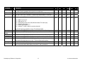
1
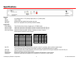
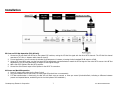
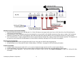
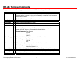
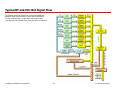
Product Manual
ICC-HE / ICW-HE
Head-End Network Controller
Ver. 2.3 November 15, 2002
17630 Davenport Rd, Suite113
Dallas, TX 75252 USA
Tel:
972.931.2728
888.972.2728
Fax: 972.931-2765
Web: www.crwww.com
www.contemporaryresearch.com
Table of Contents
Overview.....................................................................................................................................................................................................................3
Specifications..............................................................................................................................................................................................................4
Physical ..........................................................................................................................................................................................................................4
Front Panel .....................................................................................................................................................................................................................4
Control Connections.........................................................................................................................................................................................................5
iCW-Net Connections (ICC-HE and ICW-HE) ......................................................................................................................................................................5
iCC-Net Connections (ICC-HE Only)...................................................................................................................................................................................6
Power Connections ..........................................................................................................................................................................................................6
Includes .........................................................................................................................................................................................................................6
Installation .................................................................................................................................................................................................................7
RF Coax and iCC-Net Operation (ICC-HE Only)...................................................................................................................................................................7
AC Power and Net LED operation......................................................................................................................................................................................7
iCW-Net Connection (ICC-HE and ICW-HE)........................................................................................................................................................................8
Remote Control Connection ..............................................................................................................................................................................................8
I/O Port Connection.........................................................................................................................................................................................................8
RS-232 Terminal Commands ......................................................................................................................................................................................9
RS-232 Control Protocol ...........................................................................................................................................................................................10
Overview ...................................................................................................................................................................................................................... 10
Command String Structure ............................................................................................................................................................................................. 10
Command format .......................................................................................................................................................................................................... 10
RS-232 HE Commands ..............................................................................................................................................................................................11
RS-232 Device Commands........................................................................................................................................................................................12
RS-232 Response......................................................................................................................................................................................................18
Response String Structure .............................................................................................................................................................................................. 18
RS-232 HE Response ................................................................................................................................................................................................19
RS-232 Device Response ..........................................................................................................................................................................................20
iC-Net Zones .............................................................................................................................................................................................................22
System Map ..............................................................................................................................................................................................................23
Typical RF and ICC-Net Signal Flow .........................................................................................................................................................................24
RF Channel Frequencies ...........................................................................................................................................................................................25
iCW-Net Wiring .........................................................................................................................................................................................................26
Safety Instructions ...................................................................................................................................................................................................27
Limited Warranty and Disclaimer .............................................................................................................................................................................28
Contemporary Research Corporation
2
ICC-HE/ICW-HE Manual
Overview
Contemporary Research (CR) offers two solutions for intelligent television control and distributed media management, the ICC-HE and ICW-HE Head-End Network
Controllers. Both units are capable of networking up to 4,000 iC-Net TV Controllers, Display Controllers and Tuners into a unified, interactive system. The iC-Net
network can be distributed over Category 3 or 5 wiring (iCW-Net) or over broadband RF coax (iCC-Net), communicating over the same CATV cable that carries the
system’s TV channels. ICW-series controllers deliver 2-way control and feedback over the iCW-Net wired network, while ICC2-series and ICC1-series controllers
provide 2-way and 1-way control through the iCC-Net coax network.
The ICW-HE provides 2-way iCW-Net networking, distributing iC-Net commands and responses over Category 5 or 3 wiring. Three iCW-Net ports are included,
each capable of connecting thousands of ICW-Net format controllers over wiring runs of up to 3,300 feet (1 Km). In addition, iCW-Net data can be sent to remote
locations over fiber and video conferencing codecs.
The ICC-HE features the same iCW-Net capabilities as well as distributing iCC-Net data over the CATV cable. Employing clear-channel RF frequencies to transmit
and receive data, the iCC-Net network is compatible with most CATV systems without conflict with existing channels. The bi-directional network operates over a
standard low-split cable system, simplifying installation and support.
•
•
•
•
•
Networks with up to 4,000 TVs through wired iCW-Net and broadband CATV iCC-Net networks
o iCC-Net operates through same CATV coax as TV channels, requires no additional wiring
o iCW-Net distributes data over Category 5 or 3 wiring, fiber optic cable, or codecs
Sends commands to individual devices, zones, or all units from a single RS-232 port
Interacts with CR ABC Media Retrieval Systems, iC Commander software, or custom control systems
Includes local control buttons and I/O ports that can trigger events in PC software or control systems
Provides LED feedback for network, control, and operation status
Contemporary Research Corporation
3
ICC-HE/ICW-HE Manual
Specifications
Physical
Size:
Weight:
Enclosure:
Mounting:
Front Panel
RF Out Adjust:
RS-232 TX LED:
RS-232 TX LED:
RS-232 DIP Switch:
19" [483mm] wide x 1.75" [38mm] height (1RU) x 9" [229mm] deep
3 lbs [1.36kg]
All aluminum with durable black powder coat paint
Shelf or 19” equipment rack (mounting brackets included)
Trims iCC-Net channel output, shipped set to +55 dBmV (max)
Yellow LED, lights when receiving RS-232 data on Remote Control RS-232 port
Yellow LED, lights when receiving RS-232 data on Remote Control RS-232 port
Sets RS-232 baud rate (9600 - 38.4K), 8 data bits, no parity, 1 stop bit
Selects high/low sensitivity for RF In signal
DIP
1
2
3
4
5
6
7
8
Net LED:
COM LED:
Error LED:
Reset/Default:
Emergency:
Off
RF In High
Baud
Baud
Baud
On
RF In Low*
Baud
38,400
19,200*
9,600
4,800
2,400
1,200
6
ON
OFF
ON
OFF
ON
OFF
7
ON
ON
OFF
OFF
ON
ON
8
ON
ON
ON
ON
OFF
OFF
*Default setting
Green LED for iC-Net bus, flashes once per second if network is operating, device numbers expected agree
The LED will flash twice per second if the number of present and expected devices do not match
Yellow LED blinks when a valid command is received or system response sent through the Remote Control RS-232 port
Red LED indicates a problem within the unit
White button sends press and release RS-232 response to PC software or control system
Red button sends press and release RS-232 response to PC software or control system
Contemporary Research Corporation
4
ICC-HE/ICW-HE Manual
Control Connections
Control RS-232:
DB9 female, RS-232 data link to control system or PC
RS-232
Control Port
iC-Net RS-232:
I/O 1 & 2:
I/O Applications:
5 GND
GND 5
2 RXD
TXD 3
3 TXD
RXD 2
9-pin D-sub
female
DB9 female, RS-232 data link to send iCW-Net over fiber or codec
4-pin captive screw terminal for Input/Outputs 1 and 2
2 switch closures or inputs, max 50 mA, 24 VDC, switch to GND
1 – +12 VDC
2 – Output 2
3 – Output 1
4 – GND
DC power – close pins 1 & 3 to provide DC on/off
Dry closure 2 – close pins 3 & 4 for dry contact to external power relay, AMX PC1 or similar
Sense closure (3 & 4) on Input 1 – trigger control system to power off for all rooms
iCW-Net Connections (ICC-HE and ICW-HE)
iCW-Net 2, 3
RJ-45 female 8 pin Telco jack, supports 3300 ft [1 km] of wire
RS-422/485 type data requiring at least 2 twisted wire pairs with shield or fifth conductor
iCW-Net 1:
6-pin captive-screw terminal for system wiring or use with RS-422/485-format fiber or codecs
iC-Net Expand
RJ-11 female 6-pin Telco jack
Recommended Wire: CAT5/CAT3 compatible unshielded, max 3,300 feet [1 Km] from Head End
Contemporary Research Corporation
5
ICC-HE/ICW-HE Manual
iCC-Net Connections (ICC-HE Only)
RF In:
‘F’, female, 75 ohm impedance, RF and iCC-Net from CATV system
Data Receive:
Carried over the same RF coax connection as TV channels
Return signal from system controllers
Sub-band, 5.6MHz, narrow-band signal below standard sub-band channels
-15 to +35 dBmV signal level (0 to +15 dBmV nominal)
RF Out:
F’, female, 75 ohm impedance, RF to CATV distribution to TVs, tuners, and controllers
Data Transmit:
Mid-band VHF, 74.7 MHz, narrow-band signal between channels 4 and 5
± 80 KHz max carrier deviation
+55 dBmV maximum (default)
Power Connections
Power In:
2.1mm coaxial jack (inside center conductor positive),
11 to 18 VDC, 12 VDC typical, 300 mA maximum (may be unregulated)
UL/CSA listed wall power supply (included for domestic 110 VAC/60 Hz shipments only)
Includes
10 dB RF attenuator
12 VDC Power Supply
Contemporary Research Corporation
6
ICC-HE/ICW-HE Manual
Installation
RF Coax and iCC-Net Operation (ICC-HE Only)
1. Connect an RF coax feed from RF Out to the system’s RF combiner, mixing the iCC-Net Out signal with the other CATV channels. The iCC-Net Out channel
operates at 74.7 MHz, in between cable channels 4 and 5.
2. In most applications, you will connect the included 10 dB attenuator in between, trimming the He’s standard 55 dB output to 45 dB.
3. Using an RF signal level meter, use the front panel RF Out adjustment counterclockwise to match the RF Out signal to the other CATV sources. Limit RF Out
adjustment to -10 dB, using attenuators to achieve a lower signal strength.
4. Add a Sub-CATV Diplexer after the CATV amplifier.
5. Connect the Sub-Channel output of the Diplexer to the HE RF In connection.
AC Power and Net LED operation
1. Insert DC power supply plug into the Power In jack.
2. Plug power adaptor into AC wall outlet, the front-panel LEDs should turn on momentarily.
3. If iC-Net communication is functioning, the Net LED will flash once per second, or twice per second (the double-flash, indicating a difference between
present and expected device, would be typical in the initial phase of the installation.)
Contemporary Research Corporation
7
ICC-HE/ICW-HE Manual
iCW-Net Connection (ICC-HE and ICW-HE)
1. Plug the iCW-Net RJ-45 plug into the iCW-Net jack 2 or 3. Each iCW-Net port can support cable runs of up to 3,300 feet of wire. See iCW-Net Wiring for
wiring structure and alternatives.
2. The iCW-Net port 1 uses a removable screw terminal (included) for wiring to Cat3/5 or RS-422/485 connections to fiber optics or codecs. Call Contemorary
Research to coordinate use of fiber optic equipment. Each make and model often requires different wiring and electronic solutions for proper operation.
3. The iC-Net RS-232 port is used to extend iCW-Net control to remote locations through fiber, codecs or other RS-232 format equipment. The equipment at
the remote end will need an RS-422/485 adapter to provide iCW-Net networking. See page 4 for RS-232 cable wiring diagram.
Remote Control Connection
1. Attach appropriate RS-232 cable to Remote Control RS-232 port. See page 4 for RS-232 cable wiring diagram.
2. Set desired baud rate on front-panel DIP switch. Default setting is 19.2K baud – see page 4 for DIP switch setting information.
I/O Port Connection
1. A simple contact closure can be wired to I/O 1 or 2, a press or release can trigger events in the PC or control system software.
2. In other applications, the I/O ports can act as closure outputs, activating an external power relay, 2x1 video switcher or other device.
3. You’ll have to choose application – the ports act as either an output or input, not both. See Control Connections on page 4 for wiring and rating
information.
Contemporary Research Corporation
8
ICC-HE/ICW-HE Manual
RS-232 Terminal Commands
Employ standard Windows Terminal program, set to baud rate match DIP switch setting on front of HE.
Command
Description
Commands shown in ASCII and end with carriage return (Decimal 13, Hex $0D, or Enter key.
Response displays * character to signify end of characters, or times out if no characters are
received after 2 seconds.
Echo Enable
Tip: Just hit Enter to repeat any Terminal command.
EN Enables character echo so you can see typed characters on screen.
Echo Disable
EF
Version
VE Displays HE software version.
Reset
Z!
Show Devices
SD Displays list of 2-way devices stored in HE memory. List can be created by iC Commander
software, ABC-MRC software, or Scan and Build command below.
Disables terminal character display (default).
Performs system reset.
Show Missing
Example Response: Devs Present:
257-261
263
265-271*
SM Displays list of missing 2-way devices (compared to HE memory list).
Show Present
Example Response: Devs Missing:
262 -263
264*
SP Displays number of present devices and number of devices expected.
Scan and Show
Scan and Build
Show Log
Clear Log
Example Response: Num Devs Present : 1
Num Devs Expected : 53
SZ Scans iC-Net and displays list of all 2-way devices found (does not change HE memory).
Z^ Scans iC-Net and saves list of all 2-way devices found into HE memory.
L
Returns four hex bytes, separated by commas. If any of the bytes change as you repeat the
command, there is likely an error in return communication from iC-Net devices.
DL Clears the L hex bytes to zero.
Contemporary Research Corporation
9
ICC-HE/ICW-HE Manual
RS-232 Control Protocol
Overview
RS-232 control for up to 4000 iC-Net devices is provided through an iC-series Head-End Network Controller. The ICC-HE HeadEnd manages iC-Net communication over RF Coax to ICC-series devices as well as ICW-series devices over twisted-pair Cat3/5
wiring. The ICW-HE Head-End operates on the Cat5 network only.
Each device is assigned a unique device number from 1 to 4000 to which control commands are addressed. The devices are
organized into 16 zones of 255 devices. All the devices in each zone will respond to a single “virtual device number” — one
device number that represents all devices in each zone. There is also a global device number, 4095, that will command all
devices in the system. This feature dramatically speeds up system operation and programming, because one command can
affect an entire group of devices—or all. To take advantages of this feature, review the section iC-Net Zones in this manual.
In ABC Media Retrieval Systems, we reserve the first group of devices, 1-255, for components operating on a connected
control system. Zones 1-16 are used for CR TV Controllers, Video Display Controllers and Tuners. As it’s unlikely any system
will use all 4000 devices, this may be a good device standard for your system as well.
The Remote RS-232 port on the Head-End Network Controller can communicate from 1200 to 38.4K baud. The factory default
setting is 19.2K baud, 8 data bits, No parity, and 1 stop bit.
Command String Structure
Characters in command strings are expressed in a combination of hex and
ASCII characters.
•
•
•
•
•
•
•
Single-byte hex numbers are preceded by the ‘$’ symbol
ASCII characters or strings are enclosed in single quotes
Numbers not marked as hex or ASCII are a single decimal byte
Parameters shown in < > brackets are single byte
A series of multiple commands or parameters are set apart by [ ]
brackets
Commas separate the bytes, but are not part of the protocol
Double quotes enclose the command string, but are not part of the
protocol
Contemporary Research Corporation
10
Command format
“$A5,<dh>,<dl>,<ncb>,<cmd1>,<parameter> [<cmdN>]"
$A5
<dh>
<dl>
<ncb>
<cmd1>
<parameter>
[<cmdN>]
Starts the command
The zone or high order byte of the device
The unit or low order byte of the device (0 for global zone)
The number of command bytes to follow
The first command byte
Command parameters (not used by all commands)
Multiple commands can be concatenated, with byte count
added to <ncb>
ICC-HE/ICW-HE Manual
RS-232 HE Commands
The following commands apply to the HE only. Commands addressed to controllers are included with the Product Manual for the specific device.
Command
Closures
Y_
Description
“$A5,0,0,3, ‘Y’ <I/0 Port>’ ” (7 bytes)
Turns the two internal closures on and off. Closure 1 is typically used to control the
optional buzzer, Closure 2 typically used to control an external camera power relay.
Device Status
SP
“$A5,0,0,3, ‘Y10’” turns Closure
“$A5,0,0,3, ‘Y11’” turns Closure
“$A5,0,0,3, ‘Y20’” turns Closure
“$A5,0,0,3, ‘Y21’” turns Closure
"$A5,0,0,2,'SP'" (6 bytes)
1
1
2
2
off
on
off
on
Queries the Head-End for the number of devices present on the network and the
number of devices expected.
Contemporary Research Corporation
11
ICC-HE/ICW-HE Manual
RS-232 Controller Commands
The following commands summarize RS-232 commands to iC-Net controllers. There is a high degree of compatibility between Contemporary Research devices,
most commands execute a similar action or response in nearly all units. Refer to each unit’s Product Manual for specific programming information.
Command
Description
ICC/W
IRC
ICC2
VDC
ICW
VDC
ICC
ICW
ICC/W
ZS2
ICC1
IR
Power Off
PO “$A5,<dh>,<dl>,2,’P0’ ” (6 bytes) – checks status for true power control
X
3
3
X
X
X
Power On
P1 “$A5,<dh>,<dl>,2,’P1’ ” (6 bytes) – checks status for true power control
X
3
3
X
X
X
Power Toggle PT “$A5,<dh>,<dl>,2,’PT’ ” (6 bytes) – checks status for true power control
X
3
3
X
X
X
Operating
Parameters
TM “$A5,<dh>,<dl>,3,’TM’,<setting>” (7 bytes)
X
X
X
1
1
2
Volume
VL
X
X
X
X
X
X
X
X
X
Power-up
Volume
Sets up key functions in the unit
bit 7 – 3 = 0
bit 2 – Channel up/down operation, 0=Tune Ring, 1=Send IR Keypad response
bit 1 – Numeric channel labels, 0=num labels off, 1=num labels on)
bit 0 – Alpha channel labels, 0=alpha labels off, 1=alpha labels on
“$A5,<dh>,<dl>,3,’VL’,<vol level>” (7 bytes)
Sets volume level
0 = Mute
1 – 63 = Minimum level (1) to maximum volume (63)
S5 "$A5,<dh>,<dl>,3,'S5',<volume>" (7 bytes)
Sets volume level when IRC powers up
0 = restore to previous level
1 – 63 = Set from minimum (1) to maximum level (63)
Mono/Stereo S0 “$A5,<dh>,<dl>,3,’S0’, <mode>” (7 bytes) 0=mono, 1=stereo
Bass Gain
S7 “$A5,<dh>,<dl>,3,’S7’, <mode>” (7 bytes) Sets bass gain
Treble Gain
S9 “$A5,<dh>,<dl>,3,’S9’, <mode>” (7 bytes) Sets treble gain
Notes
1 1-way models do not send a response (bit 2)
2 ICC1 does not provide channel labels or response
3 Sends discrete power on and power off commands
Contemporary Research Corporation
12
X
X
X
ICC-HE/ICW-HE Manual
Command
Description
ICC/W
IRC
ICC2
VDC
ICW
VDC
ICC
ICW
ICC/W
ZS2
ICC1
IR
T Channel Up TU “$A5,<dh>,<dl>,2,’TU’ ” (6 bytes) – Tunes to next channel up in Tune Ring
X
X
X
X
X
1
T Channel Dwn TD “$A5,<dh>,<dl>,2,’TD’ ” (6 bytes) – Tunes to next channel down in Tune Ring
X
X
X
X
X
2
Force T Chan
X
X
X
X
X
2
X
X
X
X
X
2
Channel
T? “$A5,<dh>,<dl>,2,’T?’ ” (6 bytes) – Request response for current channel
Query
Q Channel Up QU “$A5,<dh>,<dl>,2,’QU’ ” (6 bytes) – Tunes to next channel up in Tune Ring
X
X
X
1
1
1
X
X
X
X
X
X
Q Channel Dwn QD “$A5,<dh>,<dl>,2,’QD’ ” (6 bytes) – Tunes to next channel down in Tune Ring
X
X
X
X
X
X
Force Q Chan
QC “$A5,<dh>,<dl>,3,’QC’, <channel>” (7 bytes) – Tunes to a specific channel
X
X
X
X
X
X
Select Q Chan
Same special-function channels as in the T Channel Select section above
QT “$A5,<dh>,<dl>,2,’TT’ ” (6 bytes) – Tunes channel if included in Tune Ring
X
X
X
X
X
X
Ts & Qs
T-series channel commands select a channel and display the channel label on the
TV, while Q-series commands don’t show the on-screen text.
TC “$A5,<dh>,<dl>,3,’TC’, <channel>” (7 bytes) – Tunes to a specific channel
124 =
125 =
126 =
127 =
0=
255 =
Select T Chan
Notes
TT
1
2
RGB 2 input on TV
RGB input on TV
Select external A/V input (IRC/VDC also selects TV video input)
Select S-Video Input
Blank video output to TV
Unblank TV video (restore to previous channel)
Tip: Not all inputs are available on every TV make and model.
“$A5,<dh>,<dl>,2,’TT’ ” (6 bytes) – Tunes channel if included in Tune Ring
1-way models do not provide response
Does not provide channel label display, obeys both T and Q commands
Contemporary Research Corporation
13
ICC-HE/ICW-HE Manual
Command
Description
ICC/W
IRC
ICC2
VDC
ICW
VDC
ICC
ICW
ICC/W
ZS2
ICC1
IR
1
Tuner Mode
SO "$A5,<dh>,<dl>,3,'S0',<tune mode>" (7 bytes)
X
X
X
X
Tune Ring
Sets tuner mode to CATV or Broadcast/Antenna
0 = CATV
1 = Broadcast/Antenna
2 = HRC
TR “$A5,<dh>,<dl>,<ncb>,’TR’, [<chan 1>, <chan N>]” (variable bytes)
X
X
X
1
1
X
X
X
X
X
X
X
X
X
X
This command stores a Tune Ring, a series of preset channels accessed by channel
up/down commands.
Channel
Labels
Ex1: “$A5,<dh>,<dl>,6,’TR’, 5,4,8,11” sets ring to channels 5, 4, 8 and 11
Tip: The ring follows the stored order, channels do not have to be in ascending
order
x Ex2: “$A5,<dh>,<dl>,2,’TR’ ” clears the Tune Ring, locks unit to current channel
Tip: In the above mode, the IR Keypad channel up/down response to the HeadEnd, so the system will know the user is trying to change channels. In
response, the system could change channels on a media sources, like a VCR
or satellite. See K response note in RS-232 Responses.
Ex3: “$A5,<dh>,<dl>,8,’TR’, $82,5,$87,11” sets channels 2-5 and 7-11. You can
specify a range using MSB bit for the first channel; the next byte is the last.
TN “$A5,<dh>,<dl>,<ncb>,‘TN’,<channel>,<label>” (variable bytes)
Stores an ASCII string as the channel label. The text will appear briefly when the
channel is selected, if the feature has been activated by TM command.
Ex1: “$A5,<dh>,<dl>,3,‘TN’, ‘7’, ‘PBS’ ” unit displays PBS when 7 is selected
Ex2: “$A5,<dh>,<dl>,3,‘TN’, ‘7’ ” Clears alpha label for channel 7
Ex3: “$A5,<dh>,<dl>,3,‘TN’,0,0” Clears all alpha labels
Display Label TC “$A5,<dh>,<dl>,2,’TC’ ” (6 bytes) – Display current channel label for about 15 sec
Notes
1
1-way units do not send the K keypad responses in Ex2.
Contemporary Research Corporation
14
ICC-HE/ICW-HE Manual
Command
Closures
Description
Y-
“$A5,<dh>,<dl>,3, ‘Y’ <I/0 Port>’ ” (7 bytes)
ICC/W
IRC
ICC2
VDC
ICW
VDC
ICC
ICW
ICC/W
ZS2
ICC1
IR
X
X
X
X
X
X
X
X
X
2
X
X
X
1
1
Turns the two internal closures on and off. Closure 1 is typically used to control the
optional buzzer, Closure 2 typically used to control an external camera power relay.
Control Lock
“$A5,<dh>,<dl>,3, ‘Y10’” turns Closure 1 off
“$A5,<dh>,<dl>,3, ‘Y11’” turns Closure 1 on
“$A5,<dh>,<dl>,3, ‘Y20’” turns Closure 2 off
“$A5,<dh>,<dl>,3, ‘Y21’” turns Closure 2 on
LM “$A5,<dh>,<dl>,3,'LM',<control>” (7 bytes)
Locks out front panel and IR remote control functions.
Bit 7
Selects IR remote control operation (0=enabled, 1=disabled)
Bit 6
Selects volume control operation (0=enabled, 1=disabled)
Bit 5 - 1 Always 0
Bit 0
Selects front panel button operation (0=enabled, 1=disabled)
Device Status SP "$A5,0,0,2,'SP'" (6 bytes)
Notes
1
2
Queries the Head-End for the number of devices present on the network and the
number of devices expected.
1-way units do not respond to command
Locks out IR remote control only
Contemporary Research Corporation
15
ICC-HE/ICW-HE Manual
Command
Write Text
Description
DM
“$A5,<dh>,<dl>,<ncb>,‘DM’, <start line>,<text color>,<background color>,
<background>,<size and shadow>,<timeout>,<message bytes>” (variable bytes)
ICC/W
IRC
ICC2
VDC
ICW
VDC
ICC
ICW
ICC/W
ZS2
1
1
1
X
X
ICC1
IR
Clears current text, displays text message over video (default) or blank
background. The built-in character generator can accept up to 40 characters of
text (including carriage returns), 28 characters per line. Use a hex $0D or decimal
13 in the text as a carriage return, which will advance CG to the next line, first
space on the right.
Start Line - 1-11
Text Color - 1-7= White
Text Background Color – 0-7=Transparent (no background)
Full screen background – 0=normal insert over video, 1=blank screen (blue)
Size and Shadow – 0-3=small text with drop shadow
Time-Out – 0=15-second display, 1=persistent
Persistent text stays on screen until the next DM, or new Menu or channel.
Ex1: “$A5,<dh>,<dl>,10,‘DM’, 2,7,0,0,1,0,’TEST’ ” displays the word TEST on the
second line, white text, inserted over video, small size with drop shadow, and
timing out after 15 seconds.
Ex2: “$A5,<dh>,<dl>,2,‘DM’ ” clears on-screen display, also clears persistent text
Notes
1
The IRC and VDC use white text and clear backgrounds when it receives a Text or
Background Color parameter between 1 and 7, and accepts values 0-3 for text size
and shadow. This allows compatibility with Smart TVs mixed in the same system
that can display other colors and fonts.
Unit will respond to all formatting commands, using white text on transparent
background
Contemporary Research Corporation
16
ICC-HE/ICW-HE Manual
Command
Description
ICC2
VDC
ICW
VDC
X
X
X
Advanced
Fast Write
DN
Write Here
Clears display, writes specified text starting at column 1, row 1. $0D and hex $EA,
$EB, $DC, and $DB can be included, operate same as matching commands below.
DW “$A5,<dh>,<dl>,<ncb>,’DW’, <text> ” (variable bytes)
X
X
X
Writes specified text starting at present cursor position. Accepts same Hex as DN.
“$A5,<dh>,<dl>,4,’DG’, <row>, <column>” (8 bytes)
X
X
X
X
X
X
Row, Column DG
The following commands provide advanced CG text operation
“$A5,<dh>,<dl>,<ncb>,’DN’, <text> ” (variable bytes)
ICC/W
IRC
Cursor
Column
Cursor Row
E7
Moves the cursor to the specified row and column position. If row is 0, then row
will not be changed, and if column is 0, then column will not be changed.
“$A5,<dh>,<dl>,3,’E7’, <column>” (7 bytes) – sends cursor to specified column.
E8
“$A5,<dh>,<dl>,3,’E8’, <row>” (7 bytes) – sends cursor to specified row.
X
X
X
Return
EB
“$A5,<dh>,<dl>,2,’EB’ ” (6 bytes)
X
X
X
Clear All
EA
Moves cursor down to the first column of the next row.
“$A5,<dh>,<dl>,2,’EA’ ” (6 bytes)
X
X
X
Clear to End
DC
Clears display, sends cursor to column 1, row 1.
“$A5,<dh>,<dl>,2,’DC’ ” (6 bytes)
X
X
X
Clear Line
DB
Clear on-screen display from cursor to end of screen, position stays the same.
“$A5,<dh>,<dl>,2,’DB’ ” (6 bytes)
X
X
X
Clear Spaces
E9
Clear on-screen display from cursor to end of line, cursor position stays the same.
“$A5,<dh>,<dl>,3,’E9’, <num spaces>” (7 bytes)
X
X
X
Clears specified number of spaces, starting from cursor to the right.
“$A5,<dh>,<dl>,3,’DQ’, <time>” (7 bytes)
X
X
X
Text Timeout DQ
ICC
ICW
ICC/W
ZS2
ICC1
IR
Sets screen timeout to specified time in seconds (1-254). If time is 0 or 255, any
text on the screen will persist indefinitely, or until cleared.
Contemporary Research Corporation
17
ICC-HE/ICW-HE Manual
RS-232 Response
Contemporary Research 2-way iC-Net devices will send a response over the network whenever there is there is a change in status or command from an IR remote
or front panel.
Response String Structure
Characters in response strings are expressed in a combination of hex and ASCII characters. For clarity, the following protocol examples use the following
conventions:
•
•
•
•
•
•
ASCII characters or strings are shown enclosed in single quotes
Numbers shown that are not in single quotes are a single decimal byte
Parameters shown in < > brackets are single byte
A series of multiple commands or parameters are set apart by [ ] brackets
Commas separate the bytes, but are not part of the protocol
Double quotes enclose the command string, but are not part of the protocol
Command format:
“ ‘<’,<dh>,<dl>,<nrb>,<rb1>, <para1> [<rbN>]"
‘>’
<dh>
<dl>
<nrb>
<rb1>
<para1>
[<rbN>]
Starts the response
The zone or high order byte of the device
The unit or low order byte of the device (0 for global zone)
The number of response bytes to follow
The first response byte
Associated parameters, if any
Multiple responses may be included
Contemporary Research Corporation
18
ICC-HE/ICW-HE Manual
RS-232 HE Response
The following responses apply to the HE only.
Response
Key-I/O
K
Description
“ ‘<’,0,0,2,'K',<IR Key>" (6 bytes)
Sent when the Reset or Emergency buttons are pressed, or when I/O 1 or 2 receives
a closure. PC software or a control system connected to the Control RS-232 port can
receive the response and activate a programmed event.
Device Query
SP
101 = Reset button pressed
229 = Reset button released
102 = Emergency button pressed
230 = Emergency button released
103 = I/O 1 input closed
231 = I/O 1 input opened
104 = I/O 2 input closed
232 = I/O 2 input opened
" '<',0,0,4,'SP',<number devices present>,<number devices expected> (8 bytes)
Sent in response to HE Device Status query.
Tip: If the number of present and expected devices match, the green Net LED on
the HE will blink once per second. If the two numbers do not agree, the LED
blinks twice per second.
Contemporary Research Corporation
19
ICC-HE/ICW-HE Manual
RS-232 Device Response
The following responses are common to all iC-Net 2-Way devices.
Response
New Channel T
Description
“ ‘<’,<dh>,<dl>,2,'T',<new channel>" (6 bytes)
IR Function
Sent in response to T? command.
“ ‘<’,<dh>,<dl>,2,'F',<IR Function>" (6 bytes)
R
Sent when unit receives a new function command is pressed (1-8) or released (0) from
the IR remote.
IR Key
K
0 = Release
1 = Play
2 = Stop
3 = Pause
4 = Fast Forward
5 = Rewind
8 = Record
“ ‘<’,<dh>,<dl>,2,'K',<IR Key>" (6 bytes)
Sent when unit receives a new key command is pressed (10-23) or released (0) from
the IR remote.
0 = Release
10 - 19 = Numeric keypad entry 0 – 9
21 = Enter
22 = Channel Up
23 = Channel Down
29 = Menu
101 = Previous Channel
102 = Timer
105 = Media Menu
106 = Cursor Right
107 = Cursor Left
108 = Cursor Up
109 = Cursor Down
110 = Media Select
The 0 – 9, Channel Up/Down functions are sent only if enabled in the TM command
(Bit 2 = 1). The Channel Up/Down responses will be sent if the Tune Ring contains no
channels – see Ex2 in the Tune Ring command section.
Contemporary Research Corporation
20
ICC-HE/ICW-HE Manual
Response
IR Menu
M
Description
“ ‘<’,<dh>,<dl>,5,'M',<msh>, <msl>, <mph>, <mpl>" (9 bytes)
Sent when unit receives a new Menu command is pressed or released (0) from the IR
remote. Menu Selection high and low bytes are in <msh> and <msl>. Menu Parameter
high and low bytes are in <mph> and <mpl>.
A Menu command is initiated by pressing the Menu key, followed by a numeric entry,
then the Enter or Channel Up key. During the Menu process, the Channel Down key acts
as a backspace or delete key.
Some selections that need only a single numeric entry and will have a parameter value
of zero (0). Those keys are 0, 8, 9, 18, 20, 30, 900, 911, and 912.
Menu selections that will prompt the user to enter a second parameter entry are:
1 = Select Media
2 = Password
3 = Chapter Search
4 = Frame Search
11 = Channel
21 = Page Zone
22 = Page Room
25 = Go
21 = Attach Zone
32 = Attach Room
Tip: The Menu entries are active even if the TV power is off.
Contemporary Research Corporation
21
ICC-HE/ICW-HE Manual
iC-Net Zones
To simplify controlling groups of devices, iC-Net is divided into 16 zones of 255 devices. All the devices within each zone can be controlled
simultaneously by sending a command to a single “virtual device number”.
For example, noting the zone chart below, if we send a Power On command to device #256, any TV controller numbered between 257 and 511 will
instantly turn on. If we send a Power Off command to device #4095, all devices in the system will turn off.
This is an immensely powerful feature, because most systems can only address one device at time. So if you need to turn off all 50 TV in a zone,
you would need to send 50 commands. In addition to the hassles of creating multiple commands, there would be a long delay between the first and
last command. One command, instant response is easier.
ABC Media Retrieval Systems reserve Zone 0 for devices used in the central control system, 1 -15 for iC-Net devices. This structure may be useful
for your application, or you could use Zone 0 just like any other iC-Net zone.
Zone
0
1
2
3
4
5
6
7
8
9
10
11
12
13
14
15
All Zones
Tip:
First Device
1
257
512
769
1025
1281
1537
1793
2049
2305
2561
2817
3073
3329
3585
3841
Last Device
255
511
767
1023
1279
1535
1791
2047
2303
2559
2815
3071
3327
3583
3839
4000
Virtual Device
0
256
512
768
1024
1280
1536
1792
2048
2304
2560
2816
3072
3328
3584
3840
4095
You've probably figured out that you never want to assign a virtual device number to an actual device in the system. If you assigned #1536 to a device,
all the TV controllers in Zone 6 would respond every time you sent a command to that one device.
Contemporary Research Corporation
22
ICC-HE/ICW-HE Manual
System Map
One of the key tasks for iC-Net integrators is to create a logical System Map, assigning device numbers to TV controllers so they fall into logical
zones. The device mapping could be sorted by type or location; whichever suits the application.
iC-Net Zone
1
2
3
4
Zone
W 1st Floor
W 2nd Floor
E 1st Floor
E 2nd Floor
Room
Device
W151
W152
W153
W154
257
258
259
260
W251
W252
W253
W254
E151
E152
E153
E154
E251
E252
E253
E254
Contemporary Research Corporation
256
512
513
514
515
516
iC-Net Zone
Zone
5
Coffee Areas
6
1024
Device
G100
G150
G151
1281
1282
1283
Day Care
TV 1
TV 2
7
Hallways
W1
W2
E1
E2
768
769
770
771
772
Room
8
Office
Admin
A/V Center
All Zones
All
1280
1536
1537
1538
1792
1793
1794
1795
1796
2048
2049
2050
4095
1025
1024
1025
1026
23
ICC-HE/ICW-HE Manual
Typical RF and ICC-Net Signal Flow
This diagram shows the structure of a typical Contemporary
Research media retrieval system. One of the key aspects for
iCC-Net communication is to provide a forward and return
(sub-channel) path for data if you’re using 2-way TV Controllers.
Contemporary Research Corporation
24
ICC-HE/ICW-HE Manual
RF Channel Frequencies
Channel
Bandwidth
Channel
Bandwidth
Channel
Bandwidth
Channel
Bandwidth
iCC-Net
5.6 (Return)
14
216.0 - 222.0
58
426.0 - 432.0
93
636.0 - 642.0
T7
5.75 - 11.75
15
222.0 - 228.0
59
432.0 - 438.0
94
642.0 - 648.0
T8
11.75 - 17.75
16
228.0 - 234.0
60
438.0 - 444.0
95
648.0 - 654.0
T9
17.75 - 23.75
17
234.0 - 240.0
61
444.0 - 450.0
96
654.0 - 660.0
T 10
23.75 - 29.75
18
240.0 - 246.0
62
450.0 - 456.0
97
660.0 - 666.0
T 11
29.75 - 35.75
19
246.0 - 252.0
63
456.0 - 462.0
98
666.0 - 672.0
T 12
35.75 - 41.75
20
252.0 - 258.0
64
462.0 - 468.0
99
672.0 - 678.0
T 13
41.75 - 47.75
21
258.0 - 264.0
65
468.0 - 474.0
100
678.0 - 684.0
2
54.0 - 60.0
22
264.0 - 270.0
66
474.0 - 480.0
101
684.0 - 690.0
3
60.0 - 66.0
23
270.0 - 276.0
67
480.0 - 486.0
102
690.0 - 696.0
4
66.0 - 72.0
24
276.0 - 282.0
68
486.0 - 492.0
103
696.0 - 702.0
iCC-Net
74.7 (Send)
25
282.0 - 288.0
69
492.0 - 498.0
104
702.0 - 708.0
5
76.0 - 82.0
26
288.0 - 294.0
70
498.0 - 504.0
105
708.0 - 714.0
6
82.0 - 88.0
36
294.0 - 300.0
71
504.0 - 510.0
106
714.0 - 720.0
95
90.0 - 96.0
37
300.0 - 306.0
72
510.0 - 516.0
107
720.0 - 726.0
96
96.0 - 102.0
38
306.0 - 312.0
73
516.0 - 522.0
108
726.0 - 732.0
97
102.0 - 108.0
39
312.0 - 318.0
74
522.0 - 528.0
109
732.0 - 738.0
98
108.0 - 114.0
40
318.0 - 324.0
75
528.0 - 534.0
110
738.0 - 744.0
99
114.0 - 120.0
41
324.0 - 330.0
76
534.0 - 540.0
111
744.0 - 750.0
14
120.0 - 126.0
42
330.0 - 336.0
77
540.0 - 546.0
112
750.0 - 756.0
15
126.0 - 132.0
43
336.0 - 342.0
78
546.0 - 552.0
113
756.0 - 762.0
16
132.0 - 138.0
44
342.0 - 348.0
79
552.0 - 558.0
114
762.0 - 768.0
17
138.0 - 144.0
45
348.0 - 354.0
80
558.0 - 564.0
115
768.0 - 674.0
18
144.0 - 150.0
46
354.0 - 360.0
81
564.0 - 570.0
116
774.0 - 780.0
19
150.0 - 156.0
47
360.0 - 366.0
82
570.0 - 576.0
117
780.0 - 786.0
20
156.0 - 162.0
48
366.0 - 372.0
83
576.0 - 582.0
118
786.0 - 792.0
21
162.0 - 168.0
49
372.0 - 378.0
84
582.0 - 588.0
119
792.0 - 798.0
22
168.0 - 174.0
50
378.0 - 384.0
85
588.0 - 594.0
120
798.0 - 804.0
7
174.0 - 180.0
51
384.0 - 390.0
86
594.0 - 600.0
121
804.0 - 810.0
8
180.0 - 186.0
52
390.0 - 396.0
87
600.0 - 606.0
122
780.0 - 786.0
9
186.0 - 192.0
53
396.0 - 402.0
88
606.0 - 612.0
123
786.0 - 792.0
10
192.0 - 198.0
54
402.0 - 408.0
89
612.0 - 618.0
124
792.0 - 798.0
11
198.0 - 204.0
55
408.0 - 414.0
90
618.0 - 624.0
12
204.0 - 210.0
56
414.0 - 420.0
91
624.0 - 630.0
13
210.0 - 216.0
57
420.0 - 426.0
92
630.0 - 636.0
HRC Frequencies = Standard frequencies minus 1.25 MHz, except for Channel 5, Video = 78.0 MHz, Channel 6, Video = 84.0 MHz
IRC Frequencies = Same as standard frequencies, except for Channel 5, Video = 79.25 MHz, Channel 6, Video = 85.25 MHz
Contemporary Research Corporation
25
ICC-HE/ICW-HE Manual
iCW-Net Wiring
Use Category 5 or Category 3 wire, 4 pair, unshielded, 24 AWG.
The iCC-HE and iCW-HE Head-End Network Controllers include three iCW-Net ports for twisted-pair wired networking. Control wiring can be home-run to ports or
run in a star format, using punch-down blocks or RJ-45 “harmonicas” to distribute signals to multiple iCW-Net devices. Open wiring runs do not need termination.
Head-End
iCW-Net #1
Screw Terminals
PWR+
RXD+
RXDTXD+
TXDGND
6
5
4
3
2
1
Punch-down Blocks
RJ-45 Harmonicas
Wall Plates
iCW Series
iCW-Net
RJ-45
BRN/WHT
WHT/BRN
GRN/WHT
WHT/BLU
BLU/WHT
WHT/GRN
ORG/WHT
WHT/ORG
8
7
6
5
4
3
2
1
8
7
6
5
4
3
2
1
8
7
6
5
4
3
2
1
TXD+
TXDGND
RXD+
RXDNC
NC
NC
BRN/WHT
WHT/BRN
GRN/WHT
WHT/BLU
BLU/WHT
WHT/GRN
ORG/WHT
WHT/ORG
8
7
6
5
4
3
2
1
8
7
6
5
4
3
2
1
8
7
6
5
4
3
2
1
TXD+
TXDGND
RXD+
RXDNC
NC
NC
iCW-Net #2, #3
RJ-45
RXD+
RXDGND
TXD+
TXDNC
NC
NC
8
7
6
5
4
3
2
1
Contemporary Research Corporation
26
ICC-HE/ICW-HE Manual
Safety Instructions
Read before operating equipment.
1. Cleaning - Unplug this product from the wall outlet before cleaning. Do not use liquid cleaners or aerosol cleaners. Use a damp cloth for cleaning.
2. Power Sources - Use supplied or equivalent UL/CSA approved low voltage DC plug-in transformer.
3. Outdoor Antenna Grounding - If you connect an outside antenna or cable system to the product, be sure the antenna or cable system is grounded so as
to provide some protection against voltage surges and built-up static charges. Section 810 of the National Electrical Code, ANSI/NFPA No. 70, provides
information with respect to proper grounding of the mast and supporting structure, grounding of the lead-in wire to an antenna discharge unit, size of
grounding conductors, location of antenna discharge unit, connection to grounding electrodes, and requirements for the grounding electrode.
4. Lightning - Avoid installation or reconfiguration of wiring during lightning activity.
5. Power Lines - Do not locate an outside antenna system near overhead power lines or other electric light or power circuits or where it can fall into such
power lines or circuits. When installing an outside antenna system, refrain from touching such power lines or circuits, as contact with them might be fatal.
6. Overloading - Do not overload wall outlets and extension cords as this can result in a risk of fire or electric shock.
7. Object and Liquid Entry - Never push objects of any kind into this product through openings as they may touch dangerous voltage points or short out
parts, resulting in a fire or electric shock. Never spill liquid of any kind on the product.
8. Servicing - Do not attempt to service this product yourself as opening or removing covers may expose you to dangerous voltage or other hazards. Refer all
servicing to qualified service personnel.
9. Damage Requiring Service - Unplug this product from the wall outlet and refer servicing to qualified service personnel under the following conditions:
• When the power supply cord or plug is damaged.
• If liquid spills or objects fall into the product.
• If the product is exposed to rain or water.
• If the product does not operate normally by following the operating instructions. Adjust only those controls that are covered by the operating
instructions. An improper adjustment of other controls may result in damage and will often require extensive work by a qualified technician to restore
the product to its normal operation.
• If the video product is dropped or the cabinet is damaged.
• When the video product exhibits a distinct change in performance, this indicates a need for service.
Note to CATV system installer: This reminder is provided to call CATV system installer's attention to Article 820-40 of the National Electrical Code (Section
54 of Canadian Electrical Code, Part I), that provides guidelines for proper grounding and, in particular, specifies that the cable ground shall be connected
to the grounding system of the building as close to the point of cable entry as possible.
Contemporary Research Corporation
27
ICC-HE/ICW-HE Manual
Limited Warranty and Disclaimer
Contemporary Research Corporation (CR) warrants this product to be free from defects in material and workmanship under normal use
for a period of two years from the date of purchase from CR. Should such a defect occur CR will repair or replace, at their option, the
defective product at no cost for parts or labor.
This warranty extends to product purchased directly from CR or an Authorized CR Dealer. Consumers should inquire from selling dealer
as to the nature and extent of the dealer's warranty, if any.
All warranty claims must be shipped pre-paid to the factory. Call or fax to obtain a Return Material Authorization (RMA) number.
CR is not liable for any damages caused by any of its products or for the failure of any products to perform, including any lost profits,
lost savings, incidental damages, or consequential damages. CR is not responsible for any claim made by a third party or made for you
by a third party. This limitation of liability applies whether damages are sought, or a claim is made, under this warranty or as a tort
claim (including negligence and strict product liability), a contract claim, or any other claim. This limitation of liability cannot be waived
or amended by any person. This limitation of liability will be effective even if CR or an authorized representative of CR has been
advised of the possibility of any such damages.
Some states do not allow a limitation of how long an implied warranty lasts. Some states do not allow the limitation or exclusion of
incidental or consequential damages for consumer products. In such states, the limitation or exclusion of the Limited Warranty may not
apply to you. This Limited Warranty gives you specific legal rights. You may also have other rights that may vary from state to state.
You are advised to consult applicable state laws for a full determination of your rights.
Except as expressly set forth in this Limited Warranty, CR makes no other warranties, expressed or implied, including any implied
warranties of merchantability or fitness for a particular purpose. CR expressly disclaims all warranties not stated in this Limited
Warranty. Any implied warranties that may be imposed by law are limited to the terms of this Limited Warranty.
Contemporary Research Corporation
28
ICC-HE/ICW-HE Manual