1
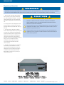
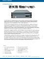
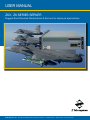
User Manual ZX3 : ZX Series Server Rugged Rack Mounted Workstations & Servers for deployed applications Z Microsystems, Inc. · 9820 Summers Ridge Road, San Diego, CA 92121 · T: 858.831.7000 · F: 858.831.7001 · www.zmicro.com REGULATORY Regulatory Information WARNING TO PREVENT FIRE OR SHOCK HAZARDS, DO NOT EXPOSE THIS UNIT TO RAIN OR MOISTURE. ALSO, DO NOT USE THIS UNIT’S POLARIZED AC PLUG WITH AN EXTENSION CORD RECEPTACLE OR OTHER OUTLETS UNLESS ALL THREE PRONGS CAN BE FULLY INSERTED 1. Use the power and video cables supplied with the product to help prevent interference with radio and television reception. The use of cables and adapters may cause interference with electronic equipment in the vicinity of this unit. 2. This equipment has been designed to meet severe conditions in military environments as specified in MIL-STD-810G, MIL-STD-461F and DO-160F. 3. This equipment is designed to meet the limits for Class A digital devices imposed by Part 15 of FCC rules. These limits are designed to provide reasonable protection against harmful interference when equipment is operating in commercial environments. This equipment generates, uses and can radiate radio frequency energy, and, if not installed and used in accordance with the instruction manual, may cause harmful interference to radio communications. CAUTION RISK OF ELECTRIC SHOCK - DO NOT OPEN CAUTION: TO REDUCE THE RISK OF ELECTRIC SHOCK DO NOT REMOVE COVER (OR BACK OF UNIT). NO USER SERVICEABLE PARTS INSIDE. REFER SERVICING TO QUALIFIED PERSONNEL. This symbol warns the user that insulated voltage within the unit may have sufficient magnitude to cause electric shock. Therefore, it is dangerous to make any kind of contact with any part inside this unit. This symbol alerts the user that important literature concerning the operation and maintenance of this unit has been included. Therefore it should be read carefully in order to avoid any problems. 4. Operation of this equipment in a residential area is likely to cause interference in which case the user will be required to correct the interference at his own expense. Changes or modifications not expressly approved by Z Microsystems could void user’s authority to operate the equipment. ZX3 ZX Series Server Contents Setup Configurations Operations Maintenance Troubleshooting Support Appendix Doc# 27-0044UM Rev B Issued 7/13/2012 2 TABLE OF CONTENTS Table of Contents Section Page 1.0 Product Overview............................................................................................................................................................ 4 1.1 About This Manual.............................................................................................................................................. 4 1.2 Product Overview............................................................................................................................................... 5 2.0 Setup.............................................................................................................................................................................. 6 2.1 ZX3 Assembly Parts........................................................................................................................................... 6 2.2 Installing the ZX3 Station in a Rack..................................................................................................................... 7 2.3 ZX3 Connections Guide...................................................................................................................................... 8 3.0 Configuring Your ZX3 Station......................................................................................................................................... 11 3.1 Removing Top Cover of ZX3 Station................................................................................................................. 11 3.2 Re-installing Top Cover of ZX3 Station.............................................................................................................. 11 3.3 Removing & Installing Memory DIMM................................................................................................................ 12 3.4 Changing or Installing a PCI Card..................................................................................................................... 12 3.5 Removing a Power Supply Module................................................................................................................... 13 3.6 Installing a New Power Supply Module............................................................................................................. 13 3.7 Removing the Lockable Face Plate Cover......................................................................................................... 14 3.8 Installing ther Lockable Face Plate Cover.......................................................................................................... 14 4.0 Operations .................................................................................................................................................................... 14 4.1 Powering on the ZX3 Station............................................................................................................................ 14 4.2 ZX3 Status Information & Indicators.................................................................................................................. 14 4.3 Removing the TranzPak2 Storage Module........................................................................................................ 15 4.4 Inserting a TranzPak2 Storage Module.............................................................................................................. 15 5.0 Maintenance ................................................................................................................................................................. 16 5.1-5.2 Cleaning and Maintaining the ZX3 ............................................................................................................. 16 6.0 Troubleshooting the ZX3 Station.................................................................................................................................... 17 7.0 Customer Support......................................................................................................................................................... 18 7.1 Replacing Parts for the ZX3 Station.................................................................................................................. 19 8.0 Appendix....................................................................................................................................................................... 20 8.1 Technical Specifications for the ZX3 Station...................................................................................................... 20 8.2 Mechanical Outlines for the ZX3 Station ........................................................................................................... 21 8.2.1 ZX3 Station....................................................................................................................................... 21 8.2.2 ZX3 Station Rear View (w/ AC & DC Power Supply).......................................................................... 22 Contents Setup Configurations Operations Maintenance Troubleshooting Support Appendix Doc# 27-0044UM Rev B Issued 7/13/2012 3 Product Overview 1.0 Product overview SAFETY PRECAUTIONS This section will provide information and assistance with the following topics: • About This Manual DANGER: To avoid shock hazard: • Product Overview • Do not remove the covers around the ZX3 Server. 1.1 About This Manual This product manual will help you through the installation, setup, and operation of your ZX3 Server. We recommend you read this manual carefully and follow the instructions in the installation chapter for verification of system functions and control settings. This manual is also available on the Z Microsystems website at www.zmicro.com. For further assistance please visit the Frequently Asked Questions section in the manual, or refer to the section dedicated to Customer Support. For added convenience and safety, you will find embedded visual cues for quick tips, warnings, new sections, and safety precautions. These are intended for quick supplemental reference and added ease in the installation and operation of the ZX3 Server. • Do not connect or disconnect the ZX3 Server during an electrical storm. • The power cord plug must be connected to a properly wired and grounded power outlet. • Any equipment to which the ZX3 Server will be attached must also be connected to properly wired and grounded power outlets. Warnings and Caution Alerts Notes and Preparation Information New Section Necessary Tools Necessary Hardware Additional Assistance for the ZX3: ZX Series Server, or other server configurations can be found on the Z Microsystem’s website along with highly customizable integration options for a wide range of platforms and applications. Use these interactive section links at the bottom of each page to quickly navigate between pages and sections. Contents Setup Configurations Operations Maintenance Troubleshooting Support Appendix Doc# 27-0044UM Rev B Issued 7/13/2012 4 Product Overview 1.2 Product Description ZX3 Server The ZX3 Station is a high performance, rack mountable, computing and graphics processing powerhouse. At only 5.20” (3U) high by 20 inches deep, this compact, rugged workstation utilizes minimal rack space and delivers an extremely flexible computing and high-capacity storage solution that is unbeatable in mission–ready applications. The ZX3 Station integrates the latest computing technology with a system architecture supporting any Extended ATX form-factor motherboards with support for up to twelve rugged hot–pluggable TP2 removable drives, a slimline DVD-RW, and an environmental control board to support proper thermal regulation. User–friendly features include a front accessible power switch, two front accessible USB ports for rapid connectivity, and a quick release top access cover for ease of service and hardware installation. Optimized for rugged conditions, the ZX3 Station hosts innovative PCI card hold–down brackets that secure cards in all three axis (X/Y/Z). In addition, the front panel provides a filtered dust door with a systems status display to quickly monitor the status of the rugged server. Dual redundant power supplies insure support for the latest multi-core processors and high-end PCI Express graphics cards. Z Microsystems’ engineers are experts in the design of systems that reduce the risk, cost and failure caused by harsh environmental conditions. Designed to exceed MIL-STD 167 for vibration and MIL-STD 461 for EMI, ZX3 Stations are a robust solution for mission–ready applications. Enhanced military options such as EMI filtered power supplies with Mil-Circular connectors, locking security panels, environmental cooling units (ECU) may be available. For more information contact your local Z Microsystems’ Sales Representative. Highlights • • • • • • Supports latest Intel Quad Core Xeon & AMD Quad Core Opteron processors 650W dual redundant AC power supply, 750W fixed DC Options 19” rack mountable Only 20 inches deep Slim 3U (5.20”) height 12 PCI expansion slots Contents Setup Configurations Operations • • • • • Ultra–secure PCI card brackets Lightweight rugged packaging Up to 12 rugged removable SATA or SAS TranzPak2 HDDs Slim DVD-RW and front accessible USB slots Environmental control board with status display Maintenance Troubleshooting Support Appendix Doc# 27-0044UM Rev B Issued 7/13/2012 5 SETUP 2.0 SETUP This section will provide information and assistance with the following topics: • ZX3 Shipping Contents WARNING Using assembly hardware that does not match specifications may damage internal components. • ZX3 Cable Connections Outline • Power Supply Options 2.1 Shipment Contents Ensure all of the following parts are included in the package received from Z Microsystems. Verify that no parts have not been damaged during shipment. If any of the parts are missing or damaged, immediately contact Z Microsystems Customer Service at 858-831-7040. NOTE: For the fastest and easiest installation of the ZX3 Server, follow the Installation Guide provided with your Server Station. • ZX3 Station • Power Cable(s) (May be standard IEC or MIL-Connect AC or DC option) TRANSPORTATION TIP: Remember to save • Installation Guide necessary to move the unit at a later date. the unit’s original shipping materials. It may be 2.2 Installing the ZX3 Station in a rack For rail installation instructions please refer to the Installation Guide that is included with your ZX Series Server. This guide will contain steps for mounting and installing the ZX Server with sliding guide rails and other custom rack features. Hardware specifications may vary based on ZX series and rack depth. If the procedure outlined in the included installation guide does not work for your particular configuration or was not included in your ZX product packaging, please contact for documentation assistance at (858) 831-7039 or you can email us at [email protected]. Contents Setup Configurations Operations Maintenance Troubleshooting Support Appendix Doc# 27-0044UM Rev B Issued 7/13/2012 6 FRONT ISO VIEW SETUP 2.3 ZX3 Connections Guide Preparations Required Cables/Connectors In preparation to setting up and connecting the ZX3, turn off the electrical power to your computer. • Power Supply Cable (AC or DC option) • Video Signal Cable (DVI, BNC) • Serial I/O Connector (USB Type B-A) Shown here are standard customer examples. 2.84 GROUNDING STUD MOUSE PORT ADD ON PCI SLOTS AC/DC POWER CONNECTORS 0 .75 17.00 8.75 PRINTER PORT MOUNTING HO (SLIDE RAILS NOT IN 20.00 U DECIMA XX = XXX = MATERIA FINISH: REAR VIEW KEYBOARD PORT MONITOR PORT USB 2.0 PORTS NETWORK ETHERNET PORT **Other ZX3 Server configurations available. Above is a sample configuration with a Supermicro X7DA8 motherboard and dual redundant military power supplies with EMI filter. ZX3 Power Supply Options Multiple power supply configurations are available for Z Microsystem’s ZX3 Server Stations. A typical dualredundant removeable AC power supply jack is pictured in the full ZX3 configuration above. If needed, a single, fixed DC power supply may be purchased. Contact your Z Microsystems Sales Representative for further questions, order information, and the latest updates and technology. Schematic outlines for AC/DC power supply configurations can be found in section 9.2.2 of the Appendix. DC Power Configuration Dual Redundant AC Power Configuration Contents Setup Configurations Operations Maintenance Troubleshooting Support Appendix Doc# 27-0044UM Rev B Issued 7/13/2012 7 COnfigurations 3.0 Configuring your ZX3 station This section will provide information and assistance with the following topics: • Updating ZX3 modules and configurations • Removing/Re-installing Lockable Face Plate Cover • Removing/Re-installing ZX3 Top Cover • Changing/Re-installing a PCI card Preparations Required Tools In preparation to any configurations change to the ZX3, turn off the electrical power to the ZX3 serve and your computer. • Philips Screwdriver • Removing/Re-installing a Power Supply Module 3.1 removing top cover of ZX3 station 1. Loosen both lock screws at the rear of the unit. 2. Using one hand, push slightly down on the f ront e dge of the top and use the other hand to pull the top from the rear or the unit. 4. Pull the top back to clear the side tongues from the grooves in the casing and lif t the top away. 5. Once you have cleared the side tongues from the grooves, lif t the lid from the ZX3 station. 3. When the top is disengaged from the locked position, use your thumbs to apply leverage while your fingers start to pull the top towards you. 3.2 REMOVING/INSTALLING MEMORY dimm 1. E a c h o f t h e M e m o r y D I M M s l o t s i s e q u i p p e d w i t h l o c k i n g l a tc h e s to s e c u r e the Memor y DIMM in place. 2. Use your fingers to push the locking latches away from the existing Memory DIMM. 3. The existing Memory DIMM will pop out of the slot. Gently remove the Memory DIMM from the slot. (CONTINUED)... Contents Setup Configurations Operations Maintenance Troubleshooting Support Appendix Doc# 27-0044UM Rev B Issued 7/13/2012 8 COnfigurations 3.3 REMOVING/INSTALLING MEMORY dimm 4. Install the new Memor y DIMM by carefully aligning the Memor y DIMM parallel to the slot and then gently but firmly inserting. 5. Carefully push the Memory DIMM in using your thumbs. 6. Secure the Memory DIMM by pulling the locking latches towards the Memory DIMM. 3.4 Changing or re-installing a pci card 1. Using a Philips screwdriver, remove the attachment screw for the selected placeholder plate. 2. Remove the plate from the unit casing. 3. Ca ref ull y i nse r t a n d se at th e n ew PCI card into the slot. Once the card is secure, select the appropriate Hold Down Support Bracket (see next step). 5. Using a Philips screwdriver, fasten the Hold Down Support Bracket to the unit casing. 6. Fasten the opposite side of the Hold Down Support Bracket to the unit’s interior spanner bracket as shown above. Shorter Height Cards Full Height Cards 4. For full height cards, use Hold Down Support Bracket that is straight across. For shorter height cards, use bracket with the step down bar (see above). 7. Adjust height of the support mechanism. Support mechanism slides up and down, Make sure of proper engagement to PCI card and tighten with a screw-driver. Contents Setup Configurations Operations Maintenance Troubleshooting Support Appendix Doc# 27-0044UM Rev B Issued 7/13/2012 9 COnfigurations 3.5 replacing a fan 1. If there is a red light on the front panel then a fan needs to be replaced 2. Using a Philips screwdriver, Remove the three screws from the air flow baffle. 7. Lift and remove fan unit from fan assembly. 3. Lif t and remove the air flow baf fle. 4. Using a Philips screwdriver, unfasten the rear fan cover. 5. Lift and remove the rear fan cover. 6. Disconnect the fan connector from the circuit board. 3.6 re-installing top cover of ZX3 station 1. Place cover loosely onto ZX3 station. When placed on the station, make sure your side flanges properly align with the corresponding slots. 2. Using one hand, push slightly down on the front edge of the top. Contents Operations Setup Configurations Maintenance 3. Use both hands to push the top cover from the rear or the unit. Troubleshooting Support Appendix 4. When the top is firmly seated onto the station casing, turn the attachment screws at the rear of the top cover to secure . Doc# 27-0044UM Rev B Issued 7/13/2012 10 COnfigurations 3.7 Removing a power supply module NOTE: If one of the power supply modules is WARNING: A failed power supply will removed, then the system will still operation be identified by an audible alarm. This with only one remaining power supply. alarm may vary based on your specific motherboard. 1. Using your fingers, twist to remove both screws from the rear top plate of the Power Supply module 2. Insert a finger into the handle and begin to pull the module from the station. 3. G e ntl y bu t f i r m l y c o n t i n u e to p u l l t h e Power Supply module out of the ZX3 station . 3.8 Installing a new power supply module NOTE: Different power supply options are available. Step 3 (below) is an example of dual redundant power supplies with military connectors. Step 4 (below) is an example of dual redundant power supplies with IEC connectors. 1. Carefully position the Power Supply module to the docking bay. 3. Push the unit all the way into the ZX3 station and verify the rear of the Power Supply module is flush with the casing. Contents Setup Configurations Operations 2. Using your f inger inser ted into the handle on the rear of the Power Supply Module, firmly push the module into the docking bay. 4. Using your fingers, twist to refasten the security screws of the Power Supply module to the ZX3 station. Maintenance Troubleshooting Support Appendix Doc# 27-0044UM Rev B Issued 7/13/2012 11 COnfigurations 3.9 removing the lockable face plate cover 1. Using the provided key, turn to the right to unlock the face plate cover. 2. Using your fingers, twist to release the attachment screws on the left side of the face plate cover. 3. Pull the right side of the face plate cover away from the right support bracket. NOTE: The Lockable Face Plate Cover is an option available only to certain models. 4. Slide the face place cover away and to w a r d s t h e r i g h t f r o m t h e l e f t s i d e support bracket. 3.10 installing the lockable face plate cover 1. The face plate cover has small flanges on the left side that perfectly fit within corresponding slots on the suppor t bracket on the left side. 2. The top of the left support bracket has a corresponding slot to accept the face place cover flanges. 3. The bottom of the left support bracket also has a corresponding slot for acceptance of the flange 4. Align the flanges on the left side of the face plate cover with their corresponding slots on the left support bracket. 5. When the left flanges are secured in the support bracket, position the right side of the face flat cover onto its corresponding support bracket. 6. W he n both side s are se cured onto their respective suppor t brackets, turn the key to lock the face plate cover. Contents Setup Configurations Operations Maintenance Troubleshooting Support Appendix Doc# 27-0044UM Rev B Issued 7/13/2012 12 operations 4.0 Operations This section will provide information and assistance with the following topics: • Powering up the ZX3 Station • ZX3 Status Information & Indicators • Inserting & Removing Tranzpak2 Storage Modules 4.1 Powering on the ZX3 station 1. To power up the ZX3, press and hold (about 1 second) the Power Supply Switch at the center right side of the unit. 2. T he display may pos sibly indic ate items that require attention. If such is the case, please refer to the “Troubleshooting” in the Appendix. 4.2 ZX3 Status Information & Indicators The ZX3 features status lights to effectively monitor the activities of the product: Fan LED – (LED with “Fan” text and fan symbol) Power On LED 1.Green = system fans are running normally 1.Amber = 5V standby available, system is in standby (meaning OFF) mode. 2.Amber = one or more system fans is malfunctioning 2. Green = system is ON. 3.RED = all system fans are malfunctioning or system fans are not installed 3.OFF = system is not connected to an AC power source Power Switch OT (Over Temp) LED 1. OFF = system temperature is normal 2.Red = system temperature is reaching critical condition. User intervention is needed. HD LEDs 1. O FF = No hard drive activity or no hard drive connected 2. Blinking amber = Indicates hard drive activity HEATER LED 1. RESERVED – Only in use for systems with optional heater Contents Setup Configurations Operations Maintenance LAN LED 1 and 2 1. B linking green = LAN port is connected and functioning normally 2. O FF = LAN port is not connected and/or disabled Troubleshooting Support Appendix Doc# 27-0044UM Rev B Issued 7/13/2012 13 operations 4.3 Removing the Tranzpak2 storage Module 1. Slide the locking catch towards the right to allow the locking handle to spring open. 2. The locking handle will swing out. 3. Push the locking handle to the lef t. This will disconnect the TranzPak2 from the rear connector. 4. Gently but firmly begin to pull the TranzPak2 module out as it slides off the grounding contacts. 4.4 Inserting the tranzpak2 storage module 1. Raise the TranzPak2 module to the slot. and insert into the docking bay . 2. Use your thumb to gently push on the TranzPak2 thumb plate in order to slide the module into the docking bay 3. Gently push on the TranzPak2 thumb plate until the module is seated against the rear connector. 4. Press the locking handle until it snaps into place. Contents Setup Configurations Operations Maintenance Troubleshooting Support Appendix Doc# 27-0044UM Rev B Issued 7/13/2012 14 Maintenance 5.0 Maintenance WARNING This section will provide information and assistance with the following topics: • Cleaning the ZX3 Server Be sure to turn off the power before you perform any maintenance on the server. • Replacing the ZX3 Air Filter 5.1 Cleaning the ZX3 Server Unplug the ZX3 server from the power outlet before cleaning. WARNING • To clean the surface of the ZX3, lightly dampen a soft, clean cloth with water or mild detergent and wipe the surface gently. It is recommended that users do not service the server. User maintenance is restricted to removal and installation of modules and COTS parts, and to cleaning as explained below. CAUTION: Do not use benzene, thinner, ammonia or any volatile substance to clean the server housing. These chemicals may damage the unit. 5.2 Replacing the ZX3 air filter 1. Remove the ZX3 station face plate by twisting the screws on the lef t side of the unit. Repeat the procedure on the right side. 2. Remove the casing front cover from the ZX3 station. 4. Install the new filter to the unit and use your fingers to press it firmly into place. 5.Reattach the face plate and tighten the screws on both sides Contents Setup Configurations Operations Maintenance Troubleshooting Support 3. Remove the existing air filter strip from the unit and discard.. Appendix Doc# 27-0044UM Rev B Issued 7/13/2012 15 Troubleshooting 6.0 Troubleshooting the ZX3 Station This section will provide information and assistance with the following topics: • Troubleshooting Topics for the ZX3 Station • Frequently Asked Questions about the ZX3n Station Troubleshooting Topics In the event that the ZX3 Server experiences technical problems please refer to the following troubleshooting topics for potential resolution. For our trained Z Microsystems Customer Service and Support Technicians to better serve you during this recovery stage, we recommend that you take a moment to observe and make a preliminary diagnosis so that we may expedite this process. If the following problems occur on your ZX3 Server , follow the steps provided below. No Power to the System 1. Check that the power cable is properly connected to the power supply. 2. Check that the system is receiving power. For example, take note of illuminated LED’s, hear the hum of fans or other moving internal components. 3. Check that power to the power supply is engaged. 4. Check that the power source (e.g. socket, extension cord, or other source) is live and receiving power itself. 5. If none of the above resolve the problem, contact Z Microsystems’ Customer Service Department. System Beeps Note the number of beeps and/or its sequence. The motherboard’s user manual should contain a reference list for beep patterns and respective indications. If no motherboard documentation is available, a user manual can often be found at the manufacturer’s website. Contact Z Microsystems’ Customer Service Department for further assistance. Audible Alarm: An audible alarm may be sounded, indicating a failed power supply. In the event a power supply fails, replace per procedure on page 12. Drivers For help with driver updates and other software please refer to the manufacturer’s CD or website. Additional information can be found on our website www.zmicro.com from the Resources > Downloads navigation filter. www.zmicro.com/downloads/drivers.html. Contact Us: If these procedures do not provide solutions to the problems you are experiencing, please contact Z Microsystems Customer Service Department at (858) 831-7040 Monday through Friday during the hours of 8:00AM - 5:00PM Pacific Standard Time. You can also email us at [email protected]. Contents Setup Configurations Operations Maintenance Troubleshooting Support Appendix Doc# 27-0044UM Rev B Issued 7/13/2012 16 Customer Support 7.0 Customer support NOTE: If possible, stay by the computer. NOTE: More help, late-breaking news, and The Z Microsystems Technical Support details of the latest accesories for Z Micro Representative may wish to go through the products can be found on our website at : problem over the telephone. www.zmicro.com Technical Support If you are unable to correct the problem yourself, contact Z Microsystems at: Phone: Fax: Website: Email: (858) 831-7040 (858) 831-7001 www.zmicro.com [email protected] Before calling, please have available as much of the following informationa s possible: 1. Model and serial number for the label on the monitor. 2. Purchase P.O. 3. Description of the problem 4. Computer type and model 5. System configuration (hardware fitted, etc.) 6. System BIOS version number 7. Operating System and version number 8. Display driver version number 9. Video Adapter Type Documentation Assistance If you are unable to find documentation for your specific product, contact Z Microsystems at: Phone: Email: (858) 831-7039 [email protected] Customer Feedback We value feedback on our products, their performance, problems found, and welcome all suggestions. Please send to: Customer Service Z Microsystems 9820 Summers Ridge Road San Diego, CA 92121 or www.zmicro.com Contents Setup Configurations Operations Maintenance Troubleshooting Support Appendix Doc# 27-0044UM Rev B Issued 7/13/2012 17 Customer Support 7.1 Replacing Parts for the ZX3 Station If the Z Microsystems Technical Support Engineer determines that the product needs to be replaced, a Customer Service Representative will issue a Return Material Authorization (RMA) number. An RMA number is required to return a product to Z Microsystems, regardless of the reason for the return. The Z Microsystems Customer Service Department/RMA Request Form will ask the customer to provide the following information: • model number of the defective product • serial number of the defective product • firmware revision (as detailed in the “Information” section of the Main Menu • problem with the defective product • return “ship to” address • the name and address of the company department to which we will send the invoice (if product is out of warranty or is different from the “ship to” address. • phone number and e-mail address of contact • purchase order number (PO #) You will be given an RMA number and will be asked to send the product to: Z Microsystems ATTN.: (RMA#) It is very important to reference the RMA# 9820 Summers Ridge Road San Diego, CA 92121 Product Disclaimer Z Microsystems warrants that every product is free from defects in materials, workmanship, and conforms to Z Microsystems’ stringent specifications. Z Microsystems calculates the expiration of the warranty period from the date the product is shipped. This means that the ship date on y our invoice is your product ship date unless Z Microsystems informs you otherwise. During the warranty period, Z Microsystems will provide warranty service under the type of warranty purchased for the product. Replacement parts will assume the remaining warranty of the parts they replace. If a product does not function as warranted during the warranty period, Z Microsystems will repair or replace the part (with a product that is at minimum, functionally equivalent) without charge. If the product is transferred to another user, the warranty service is available to that user for the remainder of the warranty period. Z Microsystems’ warranties are voided if the covered product is damaged due to an accident or abuse. The warranty is voided if the product is shipped with insufficient package protection. Under no circumstances is Z Microsystems liable for any of the following: 1. Third-party claims against you for losses or damages. 2. Loss of, or damage to, your records or data. 3. Economic consequential damages (including lost profits or savings) or incidental damages, even if Z Microsystems is informed of the possibility. Some jurisdictions do not allow the exclusion or limitation of incidental or consequential damages, so the above limitation or exclusion may not apply to you. This warranty gives you specfic legal rights and you may also have other rights that vary from jurisdiction to jurisdiction. Warranty does not take effect until full payment is received by Z Microsystems. Contents Setup Configurations Operations Maintenance Troubleshooting Support Appendix Doc# 27-0044UM Rev B Issued 7/13/2012 18 Appendix 8.0 Appendix 8.1 Technical Specifications for the ZX3 Station The ZX Series Servers are meticulously engineered to be adaptable and suited for an array of field operations and applications. These are standard ZX Series specifications. Other configurations may cause specifications to vary. System Capacities Up to 12 TranzPak 2 storage modules, SATA or SAS drives available Up to 192GB of system memory depending on the motherboard of choice Power Supply Dual Redundant AC Power Supply w/ standard EMI filter | Fixed DC Power Supply w/ Optional EMI filter Total Output Power: 650W max AC power | 750W max DC power AC Input Range: 90-264V AC Input Frequency: 47-63Hz, 400Hz 24V DC Supply Option DC Input Range: 18V – 36V Max Input Current: 35A Physical Total Size 5.20”H x 17.15”W x 20.00”D (inside rack) Total Weight Approximately 35 lbs. Storage Option SATA or SAS Operating Temp 0° to 50° Celsius Non-Op Temp -40° to +70° Celsius Op HumidityUp to 95% relative humidity per MIL-STD-801F section 507.4 (optional conformal coated Environmental boards required) Up to 95% relative humidity per MIL-STD-810F section 507.4 for 48 hours with non-conformal coated boards. Operating Altitude Up to 10,000 ft. Non-Op Altitude Up to 40,000 ft. VibrationConstant 0.5g’s from 5 to 50Hz per MIL-STD-167-1 Operating Shock40g’s, 11ms, 1/2 sine in X-Y-Z axis per MIL-STD-801F Section 516.5 EMI CENELEC 55022 MIL-STD-461E: CE102, RE 102, CS101, CS114, CS115,CS116 (NOTE: Properly shield cables required) Fungus Non Nutrients / contaminants Reliability Operating Life 10 Years Maintainability < 20 minutes at line replaceable unit (LRU) level Regulatory Safety Quality/Workmanship IPC / ISO 9001:2008 and applicable section of MIL-HDBK-454 UL 60950 used as a guideline MIL-SPEC A dditional extended range environmental military specifications can be met with optional enhancements. See your Z Micro representative for details. Contents Setup Configurations Operations Maintenance Troubleshooting Support Appendix Doc# 27-0044UM Rev B Issued 7/13/2012 19 APPENDIX 8.2 Mechanical outlines FOR the ZX3 Station 8.2.1 ZX3 Station 17.15 NOTES: UNLESS OTHERWISE SPECIFIED 1. APPROXIMATE WEIGHT (WITHOUT HARD DRIVES): 33 LBS 17.15 NOTES: UNLESS OTHERWISE SPECIFIED 1. APPROXIMATE WEIGHT (WITHOUT HARD DRIVES): 33 LBS 20.64 20.64 FRONT ISO VIEW FRONT ISO VIEW 17.15 S OTHERWISE SPECIFIED E WEIGHT (WITHOUT HARD DRIVES): 33 LBS 5.20 2.84 5.20 20.00 0 0 .75 .75 17.0017.00 8.75 8.75 2.84 19.00 MOUNTING HOLES (SLIDE RAILS NOT INSTALLED) MOUNTING HOLES (SLIDE RAILS NOT INSTALLED) 20.00 UNLESS OTHERWISE SPECIFIED DIMENSIONS ARE IN INCHES TOLERANCES ARE: UNLESS OTHERWISE SPECIFIED DECIMALS FRACTIONS ANGLES DIMENSIONS ARE IN INCHES 63 XX = .01 1/32 1 TOLERANCES ARE: XXX = .005 DECIMALS FRACTIONS ANGLES 63 DO NOT SCALE DRAWING XX = .01 1/32 1 MATERIAL: XXX = .005 N/A 20.64 DO NOT SCALE DRAWING MATERIAL: FINISH: N/A N/A REAR VIEW 19.00 FINISH: REAR VIEW N/A Z Micro Z Micros THIS DOCUMENT IS THE PROPERTY OF Z MICROSYSTEMS, INC. AND CONTAINS INFORMATION WHICH IS PROPRIETARY TO Z MICROSYSTEMS, INC. NO PART OF THIS THIS DOCUMENT PROPERTY OF DOCUMENT MAY IS BETHE COPIED, REPRODUCED Z MICROSYSTEMS, INC. CONTAINS OR DISCLOSED TO AND THIRD PARTIES INFORMATION WHICHWRITTEN IS PROPRIETARY TOOF TITLE WITHOUT PRIOR CONSENT Z MICROSYSTEMS, INC. NO PART OF THIS Z MICROSYSTEMS, INC. DOCUMENT MAY BE COPIED, REPRODUCED INTERPRET DIMENSIONS TOLERANCES OR DISCLOSED TO THIRD & PARTIES TITLE WITHOUT PRIOR WRITTEN CONSENT OF PER ASME Y14.5M-1994 Z MICROSYSTEMS, INC. NAME SR SRV 9830 Summers Ridge Rd Phone: (858) 831-7000 DATE INTERPRET DIMENSIONS & TOLERANCES 05/28/10 PERDRAWN ASME Y14.5M-1994 A.D. NAME CHECKED DRAWN APPROVED CHECKED 9830 Summers Ridge Phone: (858) 831-7000 DATE A.D. 05/28/10 SIZE SCALE: APPROVED DWG N FSCM B B SIZE SCALE: 0XWT1 FSCM DWG NO. UNIT WT. NONE 0XWT1 NONE UNIT WT. - FRONT ISO VIEW 5.20 0 .75 17.00 8.75 2.84 20.00 19.00 MOUNTING HOLES (SLIDE RAILS NOT INSTALLED) UNLESS OTHERWISE SPECIFIED DIMENSIONS ARE IN INCHES TOLERANCES ARE: DECIMALS FRACTIONS XX = .01 1/32 XXX = .005 ANGLES 1 DO NOT SCALE DRAWING MATERIAL: N/A Contents Setup Configurations REAR VIEW Operations MaintenanceFINISH:Troubleshooting N/A 63 THIS DOCUMENT IS THE PROPERTY OF Z MICROSYSTEMS, INC. AND CONTAINS INFORMATION WHICH IS PROPRIETARY TO Z MICROSYSTEMS, INC. NO PART OF THIS DOCUMENT MAY BE COPIED, REPRODUCED OR DISCLOSED TO THIRD PARTIES WITHOUT PRIOR WRITTEN CONSENT OF Z MICROSYSTEMS, INC. Z Microsystems, Inc. 9830 Summers Ridge Rd, San Diego, CA 92121 Phone: (858) 831-7000 Fax:(858) 831-7001 SRVR, ZX3 TITLE INTERPRET DIMENSIONS & TOLERANCES PER ASME Y14.5M-1994 NAME DRAWN DATE A.D. Support Appendix CHECKED APPROVED 05/28/10 SIZE B FSCM 0XWT1 DWG NO. Doc# 27-0044UM Rev BUNIT Issued SCALE: NONE WT. 7/13/2012 ZX3 20 SHEET 1 OF APPENDIX MOUNTING HOLES (SLIDE RAILS NOT INSTALLED 0 .75 17.00 8.75 8.2.2 ZX3 Station - Rear view (AC/DC Power supply) 20.00 UNLESS OTHERWIS DIMENSIONS ARE TOLERANCES DECIMALS FRACTIONS XX = .01 1/32 XXX = .005 DO NOT SCALE D MATERIAL: N/A FINISH: REAR VIEW Dual Redundant AC PoweR Contents Setup Configurations Operations Maintenance Troubleshooting Support Appendix Doc# 27-0044UM Rev B Issued 7/13/2012 N/A 21 Z Microsystems, Inc. 9820 Summers Ridge Road San Diego, CA 92121 Phone: (858) 831-7000 Fax: (858) 831-7001 Website: www.zmicro.com Copyright 2012 Z Microsystems, Inc. All Rights Reserved Z Microsystems, Inc. · 9820 Summers Ridge Road, San Diego, CA 92121 · T: 858.831.7000 · F: 858.831.7001 · www.zmicro.com