1
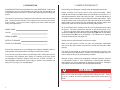
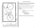
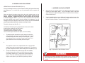
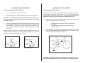
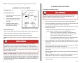
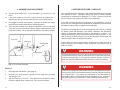
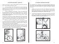
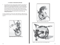
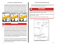
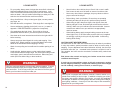
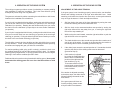
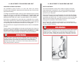
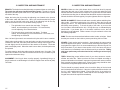
TABLE OF CONTENTS
1.
Introduction
1
2.
Owner’s Responsibility
2
3.
Parts of Your Bicycle & Location of Quick Releases
3
4.
Assembly and Adjustment
4-11
Packing List
Operation of Quick Release Levers
Installing the Seat Post
Installing the Pedals
V-Brake Assembly
Front Wheel Assembly
Full-size, High-performance bicycles that fold
Bicycle
Owner’s Manual
for Montague®, SwissBike®,
and Paratrooper® Bicycles
4
5-6
7
8
9
10-11
5.
Before Every Ride Checklist
12-13
6.
Folding the Montague Bike
14-16
7.
Unfolding the Montague Bike
17-18
8.
Road Safety
19-20
9.
Operation of the Gear System
21-22
10.
Adjustment of Handlebars & Seat
23-24
11.
Scheduled Maintenance
25
12.
Inspection and Maintenance
26-31
Tools Needed, General Inspection
Control Cables, Steering
Brakes
Wheels
Chain, Cranks, Pedals and Reflectors
Front Derailleur
Rear Derailleur
26
26
27
28
29
30
31
14.
Accessories For Your Montague
32
15.
Montague Corporation Limited Warranty
33
1. INTRODUCTION
CONGRATULATIONS on the purchase of your new MONTAGUE. This manual
is designed to give you the information you need for the safe operation and
maintenance of your new bicycle. Please read it thoroughly before riding your
bicycle.
Your bicycle’s serial number is stamped on the underside of the bottom bracket
shell. Record the serial number in this manual in the event that your bicycle
is lost or stolen. You may also want to register your serial number with your
local police department.
2. OWNER’S RESPONSIBILITY
Before riding your Montague, carefully follow all assembly instructions.
Ensure your bike is the correct size for your comfort and safety. When
standing over the frame (straddle frame) you should have a minimum of 1.0”
clearance between the boom tube and your body. Personal adjustment of
the saddle is also necessary to assure maximum safety and comfort. Open
the quick release lever on the seat tube and adjust the height of the saddle.
When seated, your leg should be fully extended with the knee slightly bent
and the ball of the foot on the pedal at the lowest pedal position.
SERIAL NUMBER
All of the X-Bike’s quick releases must be securely fastened before riding
the bicycle. The quick releases are pictured on the following page in Fig.
1. They are: the front wheel quick release lever (#23), the seat post quick
release lever (#8), the boom tube quick release lever (#9) and, the rear wheel
quick release lever (#30, not on all models). For instructions on operating
the quick release levers, see pages 5-6.
DATE OF PURCHASE
Double check to ensure all bolts and screws are tight.
PLACE OF PURCHASE
Make sure that anyone to whom you loan your Montague understands
how to work the quick release levers and how to fold and unfold the X-Bike
properly.
MODEL NAME
COLOR
Since all the components on your Montague are industry standard, repairs or
replacements can be performed at virtually any retail bicycle dealer.
If you have any questions about your Montague after reading this manual,
or encounter any problems when folding or unfolding your bike, please
call Montague’s Customer Support Team toll free at (800) 736-5348. A
knowledgeable representative will be happy to answer any questions and
help you to fully enjoy your new Montague.
The owner is responsible for required normal maintenance services, such
as those listed in the “Maintenance” sections of this booklet (pages 28-31) in
order to keep the bicycle in good operating condition.
Damage or injury resulting from negligence, improper operation, improper
or unauthorized repair or from maintenance, environmental influences,
and improper use are not warranted by Montague Corporation. Montague
Corporation excludes incidental and consequential damages.
WARNING
Make sure to read this complete manual before riding your bike. Failure
to do so, or failure to follow its guidelines could lead to serious injury or
death.
1.
2.
3.
Carefully follow the “Final Assembly Instructions” attached to your bike.
Once you have completed the assembly, read the remainder of this Owner’s
Manual.
NEVER ATTEMPT TO RIDE A BICYCLE THAT IS NOT PROPERLY
ASSEMBLED.
Inside your box you will find:
•
•
•
•
1 99% Assembled Bicycle, folded with rear wheel attached
1 Saddle with seat post
1 Front Wheel
1 Small Parts Box which includes:
•
2 Pedals (Right and Left)
•
1 Front Wheel Quick Release
•
1 15 mm Pedal Wrench
Carefully remove the bicycle and all accessories from the box to avoid
scratching the frame. Check the carton for loose parts before discarding.
25. chainstay
26. chain wheel
27. rear derailleur
28. pedal
29. rim (front & rear)
30. rear wheel quick release
Although your Montague is 99% assembled, there are a few steps that must
be completed before it is ready to ride. If you have questions or concerns
about any of these steps, please see a bicycle dealer or contact Montague’s
Customer Support Team toll free at (800) 736-5348.
1. shift levers
2. handlebar
3. brake lever
4. stem
5. saddle
6. head set
7. seat post
8. seat post quick
release
9. boom tube quick
release
10. reflectors (front
& rear)
11. boom tube
12. spoke reflectors
(front & rear)
13. tire (front & rear)
14. water bottle mounts
15. seat tube
16. rear brake
17. front brake
18. down tube
19. crank arm
20. seat stay
21. cassette
22. front derailleur
23. front wheel quick
release
24. quick release drop box
3. FIG. 1: PARTS OF YOUR BICYCLE AND LOCATION OF QUICK RELEASES
4. ASSEMBLY AND ADJUSTMENT
4.
4. ASSEMBLY AND ADJUSTMENT
OPERATION OF QUICK RELEASES (FIG. 2):
4. ASSEMBLY AND ADJUSTMENT
Since your Montague relies on quick releases for folding and general assembly
and adjustment, it is crucial that you fully understand how to operate the
levers.
Great care should be taken when locking the quick release levers on the
bicycle. Failure to properly tighten the quick release levers for the
wheels, seatpost, or frame can result in loss of control and may result
in serious injury or death. If you do not fully understand how to operate
the quick release levers, ask a bicycle mechanic for assistance, or call
Montague’s Customer Support Team toll free at (800) 736-5348. Do not ride
your bicycle without all quick releases securely locked.
4.
Once the lever is securely closed, you should not be able to move it
unless you open it again, Step 1. If you can easily move it, open the
quick release lever again and tighten the nut another half turn clockwise.
Continue with Step 3.
5.
If you have adjusted the nut too tightly and cannot push the lever to the
“close” position, open the quick release lever again and turn the nut a
half turn counterclockwise. Continue with Step 3.
The quick releases are (See Fig. 1):
Adjusting Nut
CLIX Wheel Release System (standard front wheel quick release
found on bike models prior to 2007) (#23)
The seatpost quick release lever (#8)
The boom tube quick release lever (#9)
The rear wheel quick release lever (#30, not on all models)
1.
To release a quick release lever, pull it away from the bike
and towards you until it turns over 180º and the word “open”
is visible facing the outside, away from the bicycle. If your
quick release lever is not marked “open” and “closed”, it is
open when the lever curves away from the bicycle.
1. Tightening
the Adjusting
Nut
Quick Release Lever
2.
The tightness of the lever is adjusted with the nut opposite the
release lever and by rotating the quick release lever. Turn the nut
by hand to adjust the tension while holding the lever stable (Fig. 2).
3.
5.
To lock the release lever, push lever up and over towards
the bike frame until it turns over 180º and the word “open”
is no longer visible (Fig. 2), or the lever curves toward the
bicycle. The lever is securely tightened when it leaves an
imprint on the palm of your hand from pushing it closed.
2. Locking the Quick
Release Lever
Fig. 2: Operation of Quick Release Levers
WARNING
Use extreme care when operating Quick Release Levers. Your personal
safety depends on proper and secure operation of the Quick Release
Levers.
6.
4. ASSEMBLY AND ADJUSTMENT
4. ASSEMBLY AND ADJUSTMENT
INSTALLING OR ADJUSTING THE SEAT:
INSTALLING THE PEDALS (FIG. 5):
1.
Loosen seatpost quick release lever (Fig. 3).
2.
Insert the seatpost into the seat at least to the minimum insertion line.
You will find a pair of pedals in your small parts box. The pedals have different
threads and are stamped “R” for Right and “L” for Left, on the ends of the axle
shaft to differentiate between right and left. Do not try to insert the wrong
pedal into the crank arm as it will strip the threads in the crank.
CAUTION: Do not raise seat post beyond the minimum insertion line.
To maintain rider safety, at least 2½” of seat post must be in the frame
at all times (Fig. 4).
3.
1.
To adjust seat height, loosen the seat post quick release lever (see page
5 for proper operation of quick release levers). Raise or lower the seat
post accordingly. Retighten the quick release lever securely so that
when the quick release lever is closed, the seat post cannot be rotated
in the frame.
•
•
2.
Adjust for comfort of the rider. The saddle is properly adjusted when you can
sit on the saddle, and with your knee only slightly bent (approx. 15º), reach the
pedal at its lowest point with the ball of your foot.
Align the pedal axle with the threaded hole in the respective crank arm
and secure the pedal in the crank by hand.
The right pedal is installed by turning the pedal axle
clock-wise.
The left pedal is installed by turning the pedal axle
counterclockwise.
After the pedals can no longer be turned by hand, use the 15 mm pedal
wrench (included) and tighten the pedals securely. The shoulder of each
pedal should fit tightly against the crank arm.
Min.
Insertion
Line
Fig. 3: Seat Post Installation
Fig. 4: Insertion Line
Fig. 5: Pedal Assembly
CAUTION: Always start threading the pedals into the crank by hand to
prevent stripping the threads. Do not ride the bike if pedals are loose.
7.
8.
NOTE: Left and right are determined from riding position on the bicycle.
4. ASSEMBLY AND ADJUSTMENT
4. ASSEMBLY AND ADJUSTMENT
Front Wheel Installation (FIG. 7):
V-BRAKES (FIG. 6):
Metal Cable Guide
1.
2.
3.
WARNING
End Cap
To release the brakes:
Pinch the brake arches together
with one hand.
Cable
Hook
Unit
Brake
Arch
Pull the cable guide out and up
while pushing the cable hook
unit down.
Release the brake arches,
allowing them to fall open on
either side of the wheel.
Riding with an improperly adjusted wheel quick release can allow the
wheel to wobble or disengage from the bike, causing damage to the
bicycle, and serious injury or death to the rider.
1.
Remove the front wheel quick release unit from the small parts box.
2.
Unscrew the adjusting nut from the quick release unit, and remove it and
the corresponding spring from the quick release axle.
3.
Insert the quick release unit through the wheel hub with the lever on the
left side of the wheel.
Fig. 6: Assembly of Front V-brakes
To attach the brakes:
Use one hand to pinch the brake arches together and level the cable hook unit.
Note: Left and right are determined from riding position on the
bicycle and can be found in one of the following ways:
With the other hand, squeeze the end cap into the hook unit.
•
If an arrow is embossed or printed on the sidewall of the
tire, the wheel should be positioned so the arrow points in
the direction of rotation while riding the bicycle.
•
If the manufacturer’s labels are on the tire, the wheel should
be positioned so they are on the right side of the tire.
Release the brake arches and the hook unit will lock into place
Squeeze the brake lever a few times to ensure the brakes are secured in
place.
WARNING
Always inspect the brakes before riding to be sure they are functioning properly. If you are not comfortable with the assembly instructions,
please see a bicycle mechanic or call for assistance. Brakes that are not
properly adjusted may result in loss of control and serious personal injury
or death. NEVER ATTEMPT TO RIDE A BICYCLE WITHOUT PROPERLY
FUNCTIONING BRAKES.
Brakes and Gear System: The brakes and gear system are factory set.
However, new brake and gear cables may stretch. Therefore, please check
brakes and gear system before riding your bicycle. If necessary, adjustments
to brakes and gear system can be made by you (refer to the “Operation of
Gear System’ and “Inspection and Maintenance” sections of this manual ) or
by a bicycle mechanic.
9.
4.
Put the spring back on the quick release unit and loosely screw on the
adjusting nut, leaving room on either side of the hub for the axle to fit into
the front fork.
5.
Position the wheel in the center of the front fork, keeping the opened
quick release lever on the left side of the bicycle.
6.
Guide the axle into the fork slots, being careful not to knock the brake
shoes loose.
7.
With axle inserted all the way into the fork slots, center the wheel between
the fork blades.
8.
Tighten the adjusting nut until you feel a definite resistance in the quick
release lever when you push it ½ the way to closed position.
9.
Push the lever all the way to the closed position to lock the wheel
securely in place.
10.
4. ASSEMBLY AND ADJUSTMENT
10.
Test the quick release lever. If you can rotate it up and down, it is too
loose.
11.
If the quick release is too loose, re-open the lever and tighten the
adjusting nut until you can not rotate the lever in the locked position.
12.
Re-engage the brakes (see page 9). Squeeze the brake lever tightly
few times and check that brakes are operating properly.
13.
Tires should be inflated to the pressure indicated on the tire side wall.
If tire does not have enough air, inflate it using a regulated hand or foot
pump before riding. Do not ride with tires that are not properly inflated.
Front Fork
Wheel Hub
Adjusting Nut
Axle
Tension Spring
Quick Release Lever
Fig. 7: Front Wheel Assembly
Removal:
1.
Disengage the front brakes. (See page 9).
2.
Open the hub quick release by pulling the lever away from the wheel
and turning it 180º.
3.
Slip the wheel out of the fork. If the wheel does not slide out easily,
loosen the adjusting nut several turns. Do not force the wheel.
11.
5. BEFORE EVERY RIDE - CHECKLIST
Your new Montague bike is designed and manufactured with the utmost care
and attention to detail. Montague utilizes high quality, industry standard
components to compliment our patented, FIT TM frame. We are sure you will
find your bike not only meets your needs, but exceeds them.
If you wish to replace any parts or components on your Montague, you do so
at your own risk. Montague recommends that all modifications to components
and parts be supervised by a trained bicycle technician.
Familiarize yourself with the use of all moving parts on your new bike, including
the wheels, chain and especially, your brakes. Montague has specifically
chosen an appropriate breaking system for the design of our bikes. The
braking power (ability to stop) varies among different braking systems. If you
wish to change the braking system on your bike Montague recommends you
consult a bicycle dealer for appropriate options.
Practice riding your bike at slow speeds in an area with no-traffic, such as an
empty parking lot, your driveway, or back yard before you attempt to ride in
traffic, or on trails.
WARNING
Avoid contact between your foot or toe clip and the front wheel or fender of
your bike when turning. Doing so may cause loss of control and may result
in serious personal injury. If you experience a frame vibration or “shimmy”
slow your speed immediately and take your bike to a bicycle mechanic.
WARNING
This is not a comprehensive maintenance program. Montague recommends
that you have your bicycle tuned and safely checked by a bicycle technician
on a regular basis. If you notice any irregularities in your bike and/or its
performance take it to a bike dealer before attempting to ride. Overuse of
any brake system may cause loss of control resulting in personal injury.
12.
5. BEFORE EVERY RIDE - CHECKLIST
6. FOLDING YOUR MONTAGUE BIKE
Ensure your bicycle is in proper working condition each and every time you
ride. Use the following checklist as a guide.
Your Montague bike is designed for quick folding and unfolding without the
use of tools. The following simple steps should be observed to ensure the
rider’s safety and to prevent damage or scratches when folding or unfolding
the bicycle.
Check your brakes. Press each hand lever to ensure the brakes are
moving freely and stop the bike. If your brakes are not working properly DO
NOT ride your bicycle. Practice braking at low speeds before taking your bike
out into high traffic areas or trails.
Check the attachment of both wheels. Pick the front wheel off the
ground and apply force to the wheel in a downward motion, (Fig. 8). The wheel
should remain securely in place. Grab your wheel and try to move it from side
to side. If there is any movement of the wheel do not ride your bike. Take it
to a bike dealer for service.
When the quick release lever is properly adjusted and in the closed position
you should not be able to rotate the lever in a circular motion (parallel to the
wheel). This is different from the “flipping” motion, used to open and close the
quick release lever. Repeat the same steps to check the rear wheel.
1.
Standing on the chain side of your bike, release the brake wire from
the front wheel brake (Fig. 10). To release the brakes, pinch the brake
arches together and swing the cable hook unit down. Push the end cap
and cable guide out of the hook unit. Release the arches.
2.
To unlock the front wheel quick release lever swing the lever to the open
position. Hold the adjusting nut in place while turning the quick release
lever counter clockwise 5 or 6 times to release the wheel. Remove the
front wheel from the fork and set it aside (Fig. 11).
3 Test the security of the handlebar and stem by attempting to turn the
handlebars in the stem and by twisting them from side to side with the front
wheel locked between your knees (Fig. 9). Make sure that no cables are
stretched or pinched by rotating the handlebars.
Your handlebar and stem control your ability to steer your bike, therefore, if any
part of your handlebar or stem shows signs of damage or fatigue you should
not ride your bike. Once a month check the alignment of your handlebar and
stem with your front wheel. Ensure all stem bolts are tight.
Fig. 10: Release of Front Brake
Fig. 8: Checking your Wheel
13.
Fig. 9: Checking your
Handlebar and Stem
Fig. 11: Removal of the Front Wheel
14.
6. FOLDING YOUR MONTAGUE BIKE
3.
Pull the bike up into the vertical position and stand on the chain side
with the rear tire on the ground between your feet. Open the quick
release lever on top of the boom tube (Fig. 12). Spin it counterclockwise 5 to 6 complete rotations, then with the heal of your hand press
and hold down the quick release to lower quick release nut out of
the quick release drop box while folding the bike with the handlebars
turned away from you so they fold into the rear wheel (Fig. 13). This
is best done by placing your other hand on top of the frame and
pushing away from you.
For extra compactness: open the quick release below the saddle and lower
the saddle all the way down. Then close the quick release below the saddle
(Fig. 14).
Fig. 13: Folding the Montague Bike
Fig. 12: Open Boom Tube Quick Release
Fig. 14: Final Folded Position of the Montague Bike
15.
16.
7. UNFOLDING YOUR MONTAGUE BIKE
1.
To unfold the bike place the rear wheel firmly on the ground, grasp the
rear wheel with one hand and the handlebar stem with the other and
unfold the bike. When the frame is almost completely unfolded, push
down on the opened boom tube quick release so the quick release nut
enters the quick release drop box. Secure the boom tube quick release
lever by rotating it in the open position clockwise 5 to 6 times (Fig. 15a
& 15b). Lock the quick release lever with the lever pointing towards the
saddle. Make sure the Quick Release End Nut is completely inside the
Quick Release Drop Box. See “Operation of Quick Releases”, page 5.
7. UNFOLDING YOUR MONTAGUE BIKE
4.
Adjust the saddle to proper height and lock the quick release lever. The
quick release should be tight enough so that it leaves a mark on the
palm of your hand when closing it (see page 7).
WARNING
If you do not fully understand any of the steps for unfolding your Montague
bike, be sure to ask your bicycle dealer for assistance, or call Montague’s
Customer Support Team toll free at (800) 736-5348.
DO NOT RIDE THE BICYCLE UNLESS ALL FOUR QUICK RELEASES
ARE SECURELY LOCKED!
NOTE: some models do not have rear wheel quick release.
Fig. 15a: Quick Release Operation for Final Assembly
Boom Tube
WARNING
Quick Release Lever
Do not use the quick release lever like a wing nut.
2.
3.
17.
Put the front wheel on the bicycle, with the quick release lever positioned
on the non-chain side. Guide the axle into the fork slots and center
the wheel between the fork blades. Hold the quick release lever in the
open position and tighten the adjusting nut so that you feel resistance
half way when you are closing the quick release lever. Close the quick
release lever all the way over to lock the wheel securely. The quick
release should be tight enough that it leaves a mark on the palm of your
hand when closing it. If you can rotate the quick release lever it is too
loose. Reopen the quick release lever and tighten the adjusting nut until
you can’t rotate the lever up and down when the lever is in the locked
position (see page 10, Front Wheel Installation).
To attach the front brakes, pinch the brake arches together and swing
the hook unit up. Push the end cap and cable guide into the hook unit,
allowing the cable to feed through the end of the hook unit. Release the
brake arches and the hook unit will lock into place over the end cap (see
page 9, To Attach the Brakes).
Quick Release Axle
Safety Lip
Quick
Release
End Nut
Quick Release
Drop Box
Fig. 15b: Boom Tube Quick Release
18.
8. ROAD SAFETY
•
For your safety, always wear a helmet that meets Snell or American
National Standards Institute (Ansi) Z290.4 requirements. In the
event of an accident a helmet can protect you from serious injury
and even death. A bicycle retailer will be happy to assist you in the
selection of a helmet and other useful accessories.
•
Obey all traffic laws. Obey red and green lights, one-way streets,
stop signs, etc.
•
Ride with the traffic, not against it. Ride single file in a straight line.
•
Have a satisfactory signaling device (bell, horn, etc.), to warn of
approach. RIDE DEFENSIVELY (expect the unexpected).
•
Give pedestrians the right of way. Do not ride too close to
pedestrians and alert them if you intend to pass from behind.
•
Slow down at all street intersections and look to the right and left
before crossing.
•
Always use proper hand signals for turning and stopping. Give
signals 100 ft. before stopping or turning and always return both
hands to the handlebars before stopping or turning.
•
Watch for cars pulling out into traffic and for sudden opening of car
doors.
•
Avoid potholes, drainage grates or other road surface hazards.
Cross railroad tracks at a right angle. Be careful when riding on soft
road edges, gravel, sand and uneven surfaces. Ride slowly and
avoid quick turns when riding on these surfaces.
WARNING
Use your front brake properly to ensure safe, efficient stopping. To avoid
misuse and potential injury, do not apply sudden or excessive force on
your front brake. To do so may cause your rear wheel to lift off the ground
and/or, your front wheel to slip from under you.
8. ROAD SAFETY
•
Never hitch on other vehicles, do not “Stunt” ride or race in traffic.
Don’t weave in and out of the traffic or swerve from side to side.
•
Never carry other riders or packages, they may obstruct vision or
proper control of the bicycle.
•
Before riding, check your brakes. Be sure they are operating
efficiently and that your bicycle is in perfect running condition.
•
When riding at night, always use lights, clear light on front and
flashing red light on rear, and wear light colored and/or reflective
clothing. Make sure your reflectors are intact and visible. Assume
motorists are unable to see you and ride in an appropriately
cautious manner.
•
When braking always apply stronger braking pressure to the rear
wheel (right lever). If the front brake pressure (left lever) is applied
too strongly or quickly, the bicycle may flip forward. Avoid strong
braking while turning.
CAUTION IN WET WEATHER RIDING
No brakes work as well under wet conditions as they do under dry conditions.
In rainy wet weather, special precautions must be taken to insure safety in
stopping. Proper adjustment and cable lubrication will help, but the major
precaution rests with you. Increased brake pressure is required in wet or
rainy weather and care must be exercised to maintain safety under these
conditions.
Ride slower than normal and apply your brakes sooner than normal
conditions would require.
A crash can put extraordinary stress on bicycle components, causing
them to fatigue prematurely. Components suffering from stress fatigue
can fail suddenly, causing loss of control, or serious injury.
WARNING
Your bicycle is equipped with reflectors, however, extreme caution is required when travelling at dusk or night. In addition to keeping your reflectors clean, and properly affixed to your bicycle, you must use headlights
and taillights, in addition to wearing bright, reflective clothing when riding in
poor lighting conditions. Consult your local bike shop to find accessories
appropriate for your riding needs.
19.
20.
9. OPERATION OF THE GEAR SYSTEM
The multi-gear system provides a means of maintaining a constant pedaling
rate, regardless of road level conditions. This is the most effective cycling
technique to prevent tiring over long distances.
The gears are activated by cables connecting the twist shifters or shift levers
located on the handlebar to the derailleurs.
If your bicycle is equipped with twist shifters, rotating the twist shifters towards
you moves the chain from one chainwheel (or sprocket) to the next larger
chainwheel (or sprocket). Rotating the twist shifters away from you moves
the chain from one chainwheel (or sprocket) to the next smaller chainwheel
(or sprocket).
If your bicycle is equipped with shift levers, pushing the thumb shift lever away
from you moves the chain from one chainring (or sprocket) to the next larger
chainring (or sprocket). Pulling the index finger shift lever towards you moves
the chain to the next smaller chainring (or sprocket).
9. OPERATION OF THE GEAR SYSTEM
ADJUSTMENT OF THE CABLE TENSION:
If the gear system is not functioning properly, ensure that the rear derailleur
follows each shifting command of the right twist shifter/shift lever. Cable
stretching could affect the function after some time, so that synchronization
may no longer be assured. Check and adjust as follows:
1.
Shift the chain to the center of the front chainwheel by turning the crank
forward and shifting the left twist shifter/shift lever.
2.
Shift the chain to the outermost/smallest rear sprocket by turning the
right twist shifter all the way away from you, or moving the right shift
lever all the way towards you.
3.
While turning the crank forward, rotate the right twist shifter or push the
right shift lever to the next position.
4.
The chain should move to the second rear sprocket after a maximum of
one full turn of the wheel. If it stays on the first sprocket, the tension of
the shifting cable must be increased (proceed to Step 6).
5.
If the chain jumps across the second sprocket or if it scratches the third
sprocket, the tension of the shifting cable must be decreased
(proceed to Step 6).
6.
Cable tension is adjusted
by turning the Cable Adjusting
Barrel, which is located at the
junction of the cable and the
rear derailleur (Fig. 16).
To increase tension turn the
knurled knob counterclockwise,
to decrease tension, turn the
knob clockwise.
The left shifter controls the front derailleur and the right shifter lever controls
the rear derailleur . To shift, continue pedaling at a steady pace while operating
the shifters and engage the gear you find most comfortable.
For easiest pedaling (while going up-hill or slowly), position the chain over
the smallest chainring in front and the largest sprocket in back. For hardest
pedaling (while going down-hill, or quickly), position the chain over the largest
chainring in front and the smallest sprocket in back.
Pedals and wheels must be turning forward while shifting gears. Never pedal
backward while shifting gears and never force the twist shifters or shift
levers.
If the tension is adjusted according
to the above steps, the chain should
follow all shifting commands on the
twist shifters.
If the gear system still does not
function properly, please contact
a bicycle retailer for assistance.
21.
Cable adjusting
barrel
Fig. 16: Adjustment of Cable Tension
22.
10. ADJUSTMENT OF HANDLEBAR AND SEAT
10. ADJUSTMENT OF HANDLEBAR AND SEAT
HANDLEBAR STEM ADJUSTMENT:
SEAT ADJUSTMENT:
Your handlebar’s primary function is to steer and control your bicycle,
therefore proper installation, adjustment and maintenance are crucial for your
enjoyment and safety.
Your seat and seatpost are the primary means of support for the rider.
Proper adjustment is important for your comfort and pedaling efficiency.
Ensure your seat and seatpost are securely tightened in a comfortable
position for your riding style.
To change the handlebar height, loosen the stem expander bolt two to three
turns, then tap the top of the stem handlebars to the desired height, and
retighten very tightly (175-260 lb. in or 19.8-29.4Nm). MAKE SURE THE
MINIMUM INSERTION LINE IS NOT SHOWING ABOVE THE HEADSET.
Some bikes are equipped with a stem that has an adjustable rise, or angle.
These bikes require that you tighten the angle adjusting bolt to 150-170 lb. in
(17-20.3 Nm) after first making sure the teeth are correctly engaged with the
corresponding teeth entered between the teeth of the mating part.
Note: Some bikes are equipped with handlebar stems that are not adjustable
in height.
Test the security of the handlebars in the stem and the stem in the frame, by
attempting to twist the handlebars in the stem and by attempting to turn them
from side to side with the front wheel locked between your knees (Fig. 17). Make
sure there are no cables stretched or pinched by rotating the handlebars.
WARNING
Ensure that the seat is secure by attempting to turn the seat and seatpost
in the frame. Grabbing the saddle, attempt to move the front of the saddle
up and down and side to side. If it rotates, is loose, or moves up and down,
tighten the quick release and repeat the test until there is no movement.
(see page 5 for Operation of Quick Release Levers).
Your seat post has a “Minimum Insertion Mark” 2 1/2 inches above the
bottom. When you adjust the height, always make sure this mark is inside
the frame and NOT showing.
WARNING
When adjusting the seatpost ensure the minimum insertion mark remains
inside the frame. A minimum of 2 1/2 inches (64mm) of seatpost must
remain in the frame. Riding with the seat raised above this height may
cause loss of control resulting in personal injury or damage to your bike.
If you are unsure of the safety of your handlebar system, do not attempt
to ride your bike. Never ride your bicycle with the stem raised above the
minimum insertion mark as this may cause loss of control resulting in
personal injury or death. A minimum of 2 3/4 inches (70mm) of the stem
must always remain in the frame.
Fig. 17: Hold Wheel and Try to
Turn Handlebar
23.
24.
11. SCHEDULED MAINTENANCE
12. INSPECTION AND MAINTENANCE
We recommend that you take your bicycle in to an authorized bicycle dealer
before riding it and then once a year for maintenance so that you can enjoy
your Montague bike for as long as possible. Maintenance of your bicycle
should include the following:
Regular care preserves the value and safety of your bicycle. You can carry
out the following care and inspection procedures yourself or bring the bicycle
to a dealer for maintenance. We recommend that you do take your bicycle in
to a dealer once a year for maintenance so you can enjoy your Montague for
as long as possible.
Maintenance service by a dealer
1.
Crank set: check play, adjust and retighten if necessary.
2.
Head set assembly: check play, adjust and tighten if necessary.
3.
Brake system: replace brake cables, check brake pads and replace
if necessary, adjust lever play.
4.
Gear system: grease shifting cables, check and adjust setting and
indexing function.
5.
Wheels: check alignment, realign if necessary. Check and adjust air
pressure.
6.
Chain: check, replace if necessary.
7.
Tighten mounting bolts on handlebar, saddle, brakes and hubs.
8.
Boom Tube quick release box: keep free of debris.
9.
Quick releases: check function.
Regular performance of these maintenance services will afford carefree
enjoyment of your Montague bike.
WARNING
Failure to properly maintain your bicycle may lead to damage to the bicycle, or a loss of control resulting in personal injury.
TOOLS NEEDED FOR MAINTENANCE OF YOUR MONTAGUE BIKE:
•
Small adjustable wrench
•
Large adjustable wrench
•
Set of 4, 5, 6 mm Allen keys
•
Medium Phillips screwdriver
•
Slip-joint pliers
•
Flat thin open end wrench 15mm
•
Air pump
•
Tire levers
GENERAL INSPECTION: Every week or two tighten all nuts and bolts.
Check all hardware to see that no parts are worn or damaged, that there
is correct fork and frame alignment, and that all components are seated in
proper position.
CLEANING: Clean the frame and all parts regularly with a moist cloth or
sponge. Bicycle shops offer special cleaning agents for easy care.
REFLECTORS: Reflectors should be kept clean, securely fastened and
positioned for bicycle identification at night from front, rear and lateral visibility.
Damaged units should be promptly replaced.
CONTROL CABLES: Replace worn or damaged cables. Do not kink cables.
Cables stretch with use; adjust accordingly. Keep control cable lubricated.
HANDLEBAR/STEERING: On some models, the handlebar stem may be
adjusted for your comfort. The bearing of the fork in the frame (headset)
should rotate easily without play. Adjustment of the headset requires special
tools and should be performed by a bicycle mechanic.
GRIPS: Replace worn grips. Make sure they fit snugly.
25.
26.
12. INSPECTION AND MAINTENANCE
12. INSPECTION AND MAINTENANCE
BRAKES: The brake levers should be easy to operate without too much play.
Too much play will cause insufficient braking power. The play is properly
adjusted if the brake pads meet the rim fully when the brake lever is pulled
one third of the way.
WHEELS: Make sure the quick release lever on the front wheel is properly
closed and the axle nuts, or quick release lever on the rear wheel are tight.
Wheels should be centered in fork or dropouts. Irregular noise from the wheels
or the brakes touching the rim indicates that the wheel requires maintenance.
Wheels should be checked regularly for spoke tightness and true alignment.
Adjust the brake play by turning the adjusting nuts located at the junction
of the brake cable and brake lever. When you have determined the proper
setting, turn the knurled knob at the shaft of the adjusting bolt all the way
down to the brake lever to lock the brake setting in place.
•
The right brake lever controls the rear brake. To tighten
brakes, turn the adjusting nut clockwise. To loosen brakes,
turn the adjusting nut counterclockwise.
•
The left brake lever controls the front brake. To tighten
brakes, turn the adjusting nut counterclockwise. Too loosen, turn
the adjusting nut clockwise.
Note: Left and right controls are reversed on bicycles sold in some countries.
Check brake pads regularly for wear and make sure they are properly toed in.
Viewed from the side, the brake pads should be exactly at the height of the
rim and slightly toed in the direction of the rotation of the wheel. The brake
pads must display tread. When the tread is worn down, the brake pads must
be replaced.
For safety reasons, the brake cables must be replaced every 12 months. This
should be included in the annual maintenance service by a certified bicycle
repair and maintenance shop.
ALIGNMENT: If the bicycle does not align properly, immediately bring to a
bicycle mechanic or call Montague’s Customer Support Team toll free at (800)
736-5348.
WHEEL ALIGNMENT: Wheels should rotate smoothly without wobbling from
side to side. Check the bearing play of the hubs by lifting the bicycle and
spinning the wheel. The wheel should continue to spin for several rotations
and finally cease spinning. To check the play of the hubs: try to move the
rim from side to side between the fork. During this test, no substantial play
should exist. If you detect play or if the wheel is difficult to turn, the hub
bearings must be adjusted. Please contact a bicycle mechanic to have the
hub bearings adjusted.
RIMS: The rims must be smooth and without cracks, breaks, or bulges. Check
that they are smooth on the inside to prevent puncturing the inner tube.
SPOKES: Check spoke tension regularly. Approximately the same tension
should be applied to all spokes. If there is minor loosening of the spokes, you
may tighten the nipples, but it is recommended that you take the bicycle to a
bicycle mechanic. If you detect a loose spoke or if the rim has a side play of
more than 4mm, immediately have the wheel trued by a technician. Riding
with loose spokes may cause the wheel to fail, resulting in serious injury
or death.
TIRES: Maintaining proper inflation levels of your tires ensures a smooth,
efficient and safe ride. Make sure that the tires are inflated according to
pressure indicated on tire sidewall. Improper tire pressure will cause excessive
wear, causing premature replacement. A foot or frame pump should be used.
Pressurized, unregulated pumps should not be used.
The tire should be properly seated in the rim and the fitting of the tire bead
and rim bead should be checked. If the tube is pinched between the tire and
the rim, it will explode when inflated. Ensure that the tire is not cracked or
unevenly worn. Check for bulges. Check that the valve is straight in the rim.
Irregular tires should be replaced immediately.
27.
28.
12. INSPECTION AND MAINTENANCE
12. INSPECTION AND MAINTENANCE
CHAIN: Check frequently for damage and stretch and replace if necessary.
Lubricate several times each season and after each washing or ride in the
rain. Use a lightweight, all-purpose oil, being careful to oil each link. Chain
specific oil is available from any bicycle shop. The chain must be replaced
after a maximum of 1250 miles. This requires special tools and should be
performed by a certified bicycle mechanic.
CHAINRINGS: Replace if chainring teeth are bent or damaged.
chainrings tight on crank.
Keep
CRANKS & PEDALS: Crank assembly should turn freely without side play.
Check the bearing play of the cranks by grasping the end of the crank near
the pedal thread and trying to wiggle it laterally. If you detect play, have it
corrected by a dealer.
Keep locknut tight and keep bearings clean and well adjusted. Check crank
bolt or nut (depending on axle type) regularly to make sure crank arms stay
tight.
Replace bent cranks immediately! Do not attempt to straighten.
Replace pedals if bearings are tight or frozen and if thread is lost or badly
worn. Keep pedal bearings lubricated.
REFLECTORS: Your reflectors are an important safety feature of your bike,
Do not remove them. Every three months, check the nuts and bolts holding the
front, rear, pedal and wheel reflectors and make sure that they are tight. Also
check the alignment of the front and rear reflectors, their reflective surfaces
should be perpendicular to the ground. The rear reflector should be at least
three inches below the top of the seat. KEEP REFLECTORS CLEAN AT ALL
TIMES.
FRONT DERAILLEUR ADJUSTMENT: (FIG. 18)
The derailing cage must be positioned high enough to clear the chain
wheels while shifting. If an adjustment is necessary, loosen the frame clamp
and reposition accordingly. When re-tightening the frame clamp bolt, make
sure the curvature of the derailing cage is concentric to the curvature of the
chainwheel and that the derailing cage is in line with the chainwheel.
The front derailleur should shift smoothly and easily between the
chainwheels. If the front derailleur does not shift correctly, it can be adjusted
as follows:
1.
Place left lever all the way forward, or twist shift all
the way back, and adjust screw “H” to center derailing
cage and chain over the large chainwheel.
2.
Move left shift lever all the way back or twist shift all the way
forward and adjust limiting screw “L” so the derailing cage
and chain are centered over the smaller chainwheel.
3.
Loosen the cable anchor nut and pull all slack out of the cable
through the anchor bolt. Re-tighten the cable anchor bolt securely.
These adjustments will limit the inward and outward movement of the
derailing cage so the chain will not derail to the left of the inside chainwheel
or to the right of the outside chainwheel.
Derailing
Cage
2.5 mm
Limiting
Screw
“ H”
Frame
Clamp
Bolt
Cable Anchor
Nut
Small Chainwheel
Fig. 18: Front Derailleur Adjustments
29.
30.
12 . INSPECTION AND MAINTENANCE
13. ACCESSORIES FOR YOUR MONTAGUE
REAR DERAILLEUR ADJUSTMENT (FIG 19):
Optional Accessories:
With the right shift lever all the way back or the twist shift all the way forward,
the rear derailleur should position the chain on the smallest rear sprocket
with no trace of slack in the control cable.
Folding Pedals: Folding pedals will reduce the folded width of the bicycle
by four inches and are available to fit on all models.
If the chain does not reach the smallest sprocket:
Adjust limiting screw “H” (moving it out, away from the derailleur housing)
allowing the necessary additional outward travel of the derailleur.
Once adjusted, limiting screw “H” should be moved to bottom against the
derailleur housing, stopping any additional outward travel of the derailleur
and preventing the chain from running off the smallest sprocket.
If there is slack in the cable:
Turn the barrel adjustment counterclockwise to remove slack. If the slack
is not taken up, or if the derailleur does not have a barrel adjuster, a cable
adjustment is necessary. Loosen the cable-fixing bolt freeing the cable. Pull
the cable tight and retighten bolt securely.
Carrying Case: A water resistant 420 Denier nylon carrying case is
available. It has an over-the-shoulder strap and an inner pocket for the front
wheel. See your dealer for more details.
Additional Accessories: More custom Montague accessories are also
available, and since your Montague uses standard parts and components,
you can customize your bike in numerous ways. Check out your local bike
dealer’s selection of parts and accessories.
INSTALLATION OF RACKS: Montague does not manufacture rear racks,
but recommends you use a seat post mount rack. Contact your local
bicycle retailer for further details.
With the right shift lever all the way forward, or the twist shift all the way back,
the derailleur should position the chain on the largest rear sprocket.
If the chain does not reach the largest sprocket:
Adjust limiting screw “L” to allow for
this and position it to bottom against
the derailleur housing to prevent any
additional inward travel of the
rear derailleur. This will stop the
chain from running off the inside
of the large rear sprocket.
Guide Pulley
Adjusting
Screw “H”
Cable
Adjusting
Barrel
Adjusting
Screw “L”
Cable
fixing Bolt
Tension Pulley
Fig 19: Rear Derailleur Adjustment
31.
32.
14. MONTAGUE CORPORATION LIMITED WARRANTY
Montague Corporation warrants each new Montague bicycle frame against
defects in workmanship and materials for the lifetime of the original owner.
Montague Corporation also warrants all original parts, excluding suspension
forks, for a period of one year from the date of purchase. Forks shall be
covered by the stated warranty of their original manufacturers. Paint and
decals are warranted for one year. This warranty is expressly limited to
the repair or replacement of a defective frame, fork, or defective part and is
the sole remedy of the warranty. This warranty is not transferable from the
original owner.
Claims must be made through an authorized Montague dealer. Proof
of purchase is required. In addition, a warranty registration card must be
completed and received by Montague Corporation before a warranty claim
may be processed.
This warranty does not cover normal wear and tear, improper assembly,
damage or failure due to accident, misuse, abuse or neglect, follow-up
maintenance, or installation of parts or accessories not originally intended
or compatible with the bicycle as it was sold. Modification of the frame or
components shall void this warranty.
Montague Corporation shall not be responsible for incidental or consequential
damages. Some states do not allow the exclusion of incidental or consequential
damages, so the above exclusion may not apply to you.
Labor charges for parts changeovers are not covered by the warranty.
This warranty gives the consumer specific legal rights, and those rights may
vary from place to place. This warranty does not effect the statutory rights
of the consumer.
HUMMER and all related and distinctive vehicle model body and grille designs are General Motors
Trademarks used under license to Montague Corporation.
© 2004 Montague Corporation, Cambridge, MA 02238 USA. Montague is a registered Trademark of the
Montague Corporation.
Component specifications vary by country and are subject to change without notice. All Montague bicycles
are covered under one or more patents or patents pending.
33.
Montague Corporation
P.O. Box 381118
Cambridge, MA 02238
Toll Free Phone # (800) 736-5348
International Customers Call (617) 491-7200
© 2004 Montague Corporation, Cambridge, MA, USA
Name:
Mailing Address:
Place of Purchase:
Bicycle Color:
Airline Travel
Off-road
Friend
Internet
Date of Purchase
Touring
Sailboat
Age:
Model Name:
Other:
User’s Sex: M / F
State:
MONTAGUE BICYCLE WARRANTY REGISTRATION CARD
Purchase Price:
Frame Size:
Location - City:
Serial #:
Commute
Used of Folded Montague Bicycle (if more than one applies, number by priority)
Store in home
RV
Consumer shows/Expos
Corporate
Private Plane
Government/Military
Car Trunk
Is use: Personal
Bike Trails/paths
What type of riding do you mainly use your Montague Bicycle for?
City
Bicycle Dealer
How did you hear about Montague Bicycles?
Other:
Advertisement (specify where):
News Article (specify where):
Comments:
/
/
Powerboat
From:
MONTAGUE CORPORATION
P.O. Box 381118
Cambridge, MA 02238