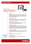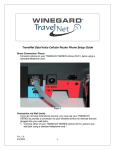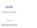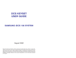
1
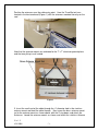
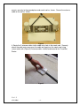
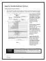
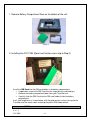
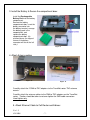
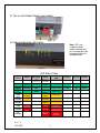
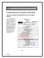
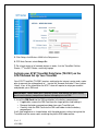
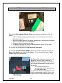
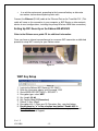
TravelNet Data/Voice Cellular Router Installation Guide
ATTENTION INSTALLER
Parts List:
• TravelNet Data/Voice Cellular Routers ( Models TN-2301/TN-2303/TN-2305)
• Green battery pack
• 110 volt power adapter
• Power line cord
• Edimax BR-6204WG WiFi Preconfigured Router
• 110 volt adapter with plug connector
• 3 foot Ethernet Cable
• RJ11 Phone Cable
• (2)External Antenna (white)
• (2)External Antenna mount with 14’ cable
• (2)Stainless Antenna Mounts
• (2)SMA to TNC adapters
• Cable Entry Cover
• Aluminum Ground Plane (7 x 7 )
• Customer Package (clear envelope)
o 7 foot Blue Ethernet Cable
o (2)Black TNC Antenna
o TravelNet Quick Start,
o TravelNet User CD
• User Manual
• Troubleshooting Guide
Other items not included:
• Sealant (Consult your vehicle manufacturer for the best sealant for your roof
material.)
Ver. 1.5
4/21/2009
-1-
TravelNet’s Cellular Router System is Preconfigured
And Ready to Install with these Easy Steps
Installation Instructions: ( Models TN-2301/TN-2303/TN-2305)
1. Install the TravelNet Router and Edimax Router equipment in a convenient place
such as upper cabinet (Velcro works well on the base of the each unit). Mount
the unit so that the diagnostic lights can be viewed without moving the TravelNet
Router and the Edimax Wireless Router.
2. Locate the 2 antennas on the roof away from other obstructions
Also, you will need sealant as recommended by your coach manufacturer, stainless
screws (4) to anchor the aluminum ground plane to roof, cable clips to anchor cable,
cable entry cover plate.
Warning – You must connect antennas to the SMA style antenna connectors on the
TravelNet Cell Router before turning it on. Failure to do this could result in erratic start up
behavior and could possibly damage the unit.
Figure 1
Ver. 1.5
4/21/2009
-2-
Position the antennas near the cable entry point. Here the TravelNet unit was
located in the front overhead (Figure 1) with the antennas mounted close by on the
roof.
Figure 2
Note that the antenna mounts are anchored to the 7” x 7” aluminum ground plane
and that everything is well sealed.
Figure 3
3. Insert the small end of the cable through the ¾” diameter hole in the stainless
antenna mount and feed the cable through. Next screw the brass antenna mount
nut to the antenna mount as shown above, with the O-ring down, and attach the
Antennas. Locate the antenna mounts as shown, and attach the stainless Antenna
Ver. 1.5
4/21/2009
-3-
mounts securely to the ground plane and coach roof as shown. Secure the antenna
cable to the roof as shown.
Figure 4
4. Route the 2 antenna cables to the cable entry hole in the coach roof. Securely
attach the cable entry cover over the cable entry point on the coach roof using
screws and caulk (Figure 5) Antenna cables should be directed to the TravelNet
Router.
Figure 5
Ver. 1.5
4/21/2009
-4-
Setup the TravelNet Data/Voice Terminal
Setting up your Carrier Account.
Your TravelNet-DV requires both a data plan for internet service and a voice plan for analog
phone service. Locate the “Account Application” (yellow sheet) in the “End User Envelope”.
Sprint Customers (TN-2303)
fill out the top half of the form
and fax back to TravelNet
Tech Support. Tech Support
will set up the line of service
with Sprint and contact you
with the provisioning
information required to
activate the TravelNet
system.
AT&T Customers (TN-2301)
to take the Account
Application form to your local
AT&T store; ask your
representative to provision a
Data Connect 5 GB line of
service and a voice plan with
your choice of minutes. Once
you have the SIM card
proceed to installation
instructions
Verizon Customers (TN2305) fill out the top half of
the form and fax back to
TravelNet Tech Support.
Tech Support will set up the
line of service with Verizon
and contact you with the
provisioning information
required to activate the
TravelNet system.
Figure 6
Attention
Installer:
Ver. 1.5
4/21/2009
AT&T systems (TN-2301) can be installed without the AT&T SIM
card, the SIM maybe installed later. Convenient access to the
bottom of the TravelNet Data Voice unit would make installing the
SIM at a later time much easier.
-5-
1. Remove Battery Compartment Door on the bottom of the unit.
Figure 7
2. Installing the AT&T SIM (Sprint and Verizon users skip to Step 3)
Figure 8
Install the SIM Card into the SIM card holder in the battery compartment.
• If applicable, remove the SIM Card from the larger plastic card holding it.
• Remove the battery compartment door from your TravelNet unit.
• Carefully slide the SIM Card into the SIM card holder inside the battery
compartment.
It will slide lengthwise as shown below, with the gold contact surface facing into the
TravelNet and the corner notch matching the plastic SIM holder outline.
NOTE; Do not touch the gold-colored areas of your SIM Card.
Ver. 1.5
4/21/2009
-6-
3. Install the Battery & Secure the compartment door.
Install the Rechargeable
Battery Pack into the battery
compartment.
Remove the battery
compartment door, insert the
battery connector into
the battery terminal, arrange
the battery pack in the
compartment, and
replace the battery
compartment door. (As
pictured above, the clipped
corner of the battery
connector will be on the left
side.)
Figure 9
4. Attach Antenna cables
Figure 10
Figure 11
Carefully attach the 2 SMA-to-TNC adapters to the TravelNet router TNC antenna
mounts.
Carefully attach the antenna cables to the SMA-to-TNC adapters on the TravelNet
router. Caution should be taken to not over tighten the SMA cable connectors.
Hand tighten only.
5. Attach Ethernet Cable to Cell Router and Edimax.
Ver. 1.5
4/21/2009
-7-
Connect Ethernet cable to the Ethernet
port on the TravelNet Network Port (as
shown) and to the Edimax WAN port (as
shown)
Antenna cables not shown for clarity.
Figure 12
6. Attach Phone Cable
Connect an RJ-11 Phone cable from a
standard phone to the Phone input (J1
Figure 13
7. Attach power cable
Connect the Power Supply Adapter to the unit’s Power Input and connect the
Power Line Cord to the Power Supply Adapter. Then, connect the Power Line Cord
plug into a power outlet. When a 12 VDC source, order the appropriate pigtail
accessories and please save the 12 volt power supply for the coach owner. Note
that if using RV’s DC power, the power inputs are polarity sensitive. NOTE: The
lead with the white stripe is +12 VDC.
Ver. 1.5
4/21/2009
-8-
8. Turn on Cell Router Power using switch.
Figure 14
9. Understanding the LED Lights
Note: LED’s are
tricolored, Green,
Amber and Red and
this corresponds to the
background colors of
the table below.
Figure 15
LED Status Table
LED
Status
Power
Messaging
Phone
Off
No Power
No
Messages
On Hook /
No WAN
Solid
AC/Batt
Normal
Voicemail
On Hook/
WAN
Batt Only
SMS
Slow
Flashing
Fast
Flashing
Solid
Slow
Flashing
Fast
Flashing
Both
AC/Batt
Charging
Low Batt
Solid
Batt Fault
Slow
Flashing
Batt
Critical
Fast
Flashing
Ver. 1.5
4/21/2009
On-Hook /
WAN Tx
Off-Hook /
WAN
Off-Hook /
No WAN
Off-Hook /
WAN Tx
Off-Hook /
WAN
Off-Hook /
No WAN
Off-Hook /
WAN Tx
-9-
Service
/SIM
Signal
Strength 1
Signal
Strength 2
Signal
Strength 3
Service / 2G
1 Bar
2 Bars
3 Bars
Service / 2.5 G
1 Bar
1 Bar
2 Bars
Service / 3G
Roam / 2G
Roam / 2.5G
Roam / 3G
No Service
PIN Locked
SIM Error /
No SIM /
Net Reject
Attention Installer: Place “User Envelope” in cabinet or drawer for your
customer.
TravelNet Data/Voice (TN-2303) Terminal Setup
Activate your Sprint TravelNet Data/Voice on the Sprint
Network
Your TravelNet Data/Voice
requires a data plan for
internet and a voice plan to
hook up the analog phone.
Locate the “Account
Application” (yellow sheet)
in the “End User Envelope”.
Fill out the top half of the
form and fax to TravelNet
Tech Support. Tech
Support will set up the line
of service with Sprint and
contact you with the
provisioning information
required to activate the
TravelNet system.
Figure 16
Ver. 1.5
4/21/2009
- 10 -
Figure 17
1. When all devices are connected and powered on, use your computer to
connect to the TravelNet Device Manager.
• Launch your Web browser (Internet Explorer or Firefox).
• Go to the browser’s address bar, type http://192.168.1.1, and press Enter or
click the green Go arrow. A “Connect to” window will be displayed.
• _ Enter the default User name (“ctek”) and Password (“1234”). The TravelNet
Device Manager will start and display the Home screen.
Figure 18
2. From the Home screen, click Activation
• Wait 5–10 minutes to see if your unit will auto-register itself on the wireless network.
If the Activation Status field displays ACTIVE, your TravelNet is ready for use.
Ver. 1.5
4/21/2009
- 11 -
Figure 19
•
Proceed to Set Up a Wireless WAN Data Connection.
TIP: Bookmark the TravelNet Device Manager access page (http://192.168.1.1).
3. For Sprint Activation, manually enter your MSL/SPC Code (4a), your MDN (10-digit
wireless phone number) (4b), and your MIN/MSID (usually also your 10-digit wireless
phone number) (4c).
4. Click Save. If you have no additional changes, click Restart to complete Activation.
The TravelNet will power down and restart.
Ver. 1.5
4/21/2009
- 12 -
5. Click Setup, click Wireless WAN in the Setup menu.
6. PSD Auto Connect select Always On
7. Do a hard restart of all network devices in order, first the TravelNet Cellular
Router, 2nd the WiFi Router, and finally laptop.
Activate your AT&T TravelNet Data/Voice (TN-2301) on the
AT&T Network Set Up Your TravelNet
Your AT&T TravelNet (TN-2301) requires a data plan for internet service and a voice
plan to connect the analog phone to . Locate the “Account Activation” Form (yellow
sheet), it has all the information the AT&T store will require to setup your account
and provide you a SIM card.
IMPORTANT: Power down your TravelNet system, and remove the green battery
pack from the battery compartment before attempting to install SIM.
1. Install the SIM Card into the SIM card holder in the battery compartment.
• If applicable, remove the SIM Card from the larger plastic card holding it.
• Remove the battery compartment door from your TravelNet unit.
• Carefully slide the SIM Card into the SIM card holder inside the battery
compartment.
It will slide lengthwise as shown below, with the gold contact surface facing into the
TravelNet and the corner notch matching the plastic SIM holder outline.
Ver. 1.5
4/21/2009
- 13 -
NOTE; Do not touch the gold-colored areas of your SIM Card.
Figure 20
2. Install the Rechargeable Battery Pack into the battery compartment. (Fig. 20
above)
• _ With the battery compartment door open, insert the battery connector into
the battery terminal.
• Arrange the battery pack in the battery compartment, so the battery connector
wire is in the top right of the compartment.
• Replace the battery compartment door.
• The battery connector will have the rounded corner side on the left when
inserted into the battery terminal.
3. Connect and hand-tighten the two Antennas (see above).
4. Connect the Power Supply Adapter to the unit’s Power Input and connect the
Power Line Cord to the Power Supply Adapter. Then, connect the Power Supply
Adapter plug into a power outlet.
5. (Optional) For optimal performance and
protection, you may elect to connect a
copper wire (not included) to the protective
earth Ground Connector Screw to ground
the device.
• _ In a building environment,
connecting to an earth ground (such
as a cold water pipe)
can protect the device and peripherals from
static and conducted electricity. It can also
reduce static or buzzing during voice calls.
Ver. 1.5
4/21/2009
- 14 -
•
In a vehicle environment, grounding to the frame and battery or alternator
can reduce static or buzzing during voice calls.
_
Connect the Ethernet (RJ-45) cable to the Ethernet Port on the TravelNet D/V. (This
cable will serve as the connection to your computer or WiFi Router or other network
device in most configurations, including the primary Wireless WAN data connection.)
Setting Up WiFi Security on the Edimax BR-6204WG
Refer to the Edimax users guide CD for additional information.
Once you have an internet connection and an unsecure WiFi connection established
proceed to setup WiFi security for your Edimax router.
Figure 21
WEP Key Setup
Figure 22
1.
2.
3.
4.
5.
6.
7.
8.
9.
Log into the Edimax WiFi Router at 192.168.2.1
Enter the Username ‘admin’ and Password ‘1234’
Go to WIRELESS SETTINGS > SECURITY
Encryption type: select WEP
Key Length: 64-bit
Key Format: Hex (10 Characters)
Default Tx Key: Key 1.
Encryption Key 1: Enter your 10 Characters Key- see chart below
Do not place an “x” in the selection box labeled “Enable 802.1x
Authentication” for normal installations. If there are any questions call
TravelNet Technical Support.
Ver. 1.5
4/21/2009
- 15 -
Figure 23
WEP Key Setup
Parameters Default
Key Length 64-bit
Key Format
Description
You can select the WEP key length for encryption, 64-bit or
128-bit. Larger WEP key length requires 26 hexadecimal
characters
Use hexadecimal digits (in the "A-F", "a-f" and "0-9" range)
to be the WEP Key.
Examples:
Hexadecimal Digits: 12345abcde or abcdef0123
10. Write key on piece of paper or on Edimax manual and keep in a safe place
with other important documentation.
11. Click on the Apply Button and wait for the System to automatically Restart.
Click OK button and security setup is complete.
12. Call TravelNet Technical Support (877) 475-7771 if there are questions
concerning Apple Computers or if you prefer to use other encryption methods.
To connect your XP computer to your wireless network
Configuring the Windows XP Wireless Clients (With WEP)
Configuration of the Windows XP wireless clients for WEP key authentication depends on
whether you are using Windows XP with SP2 or Windows XP with SP1 and whether the
wireless network adapter driver supports Wireless Auto Configuration.
Wireless Network Adapter Driver Supports Wireless Auto Configuration with
Windows XP with SP2
Ver. 1.5
4/21/2009
- 16 -
Use the following procedure to configure Windows XP with SP2 for your infrastructure
mode wireless network when the wireless network adapter supports Wireless Auto
Configuration:
1. When the computer is within range of the wireless router or Access Point (AP)
operating in your home or small business, Windows XP should detect it and prompt
you with a Wireless networks detected message in the notification area of your
taskbar.
2. Click the notification message. If you are not notified, right-click the wireless
network adapter in Network Connections, then click View Available Wireless
Networks. In either case, you should see a Choose a wireless network dialog box
with the name of your wireless network. (If the “TravelNet xxxx” wireless network
is not displayed, it may be necessary to reset the unit by removing its power plug for
10 seconds, then reinsert the power plug and wait 45 to 60 seconds). Then select the
“View Available Wireless Networks” again.
3. Double-click your wireless network name. Windows XP will attempt to connect to
your wireless network.
4. Because Windows XP has not been configured with the WEP key for your wireless
network, the connection attempt will fail and Windows XP will prompt you with a
Wireless Network Connection dialog box. Type the WEP key in Network key and
Confirm network key, and then click Connect.
5. If the status message for your wireless network in the Choose a wireless network
dialog box is Connected, you are done. If the status message for your wireless
network in the Choose a wireless network dialog box is Authentication did not
succeed, click Change the order of preferred networks in the list of Related tasks.
From the Wireless Networks tab of properties of your wireless network adapter,
click the name of your wireless network in Preferred networks, and then click
Properties.
6. In Network Authentication, click WEP.
7. In Network key, type the WEP key as configured on the wireless Access Point (AP).
In Confirm network key, retype the WEP key.
8. Click OK to save changes to the wireless network.
9. Click OK to save changes to the wireless network adapt
To connect your Windows Vista computer to your wireless network
View and connect to available wireless networks
Applies to all editions of Windows Vista.
If you have a mobile PC, you can see a list of available wireless networks, and then connect
to one of those networks, no matter where you are. The wireless networks appear only if your
computer has a wireless network adapter installed and the adapter is turned on.
Ver. 1.5
4/21/2009
- 17 -
1. Open Connect to a Network by clicking the Start button
Connect to.
, and then clicking
2. In the Show list, click Wireless.
You'll see a list of the wireless networks currently available. If you do not see a network
listing similar to this example: TravelNet 1234, it may be necessary to reset power on the
WiFi router, wait 45 to 60 seconds and refresh the “View Available Wireless Networks”.
You'll see a list of the wireless networks currently available.
3. Click a network, and then click Connect.
If you don't see the network you want to connect to, click Set up a connection or
network. A list of options will appear that includes manually searching for and connecting
to a network, as well as creating a new network connection.
Some networks require a network security key or passphrase. To connect to one of those
networks, ask the network administrator or the service provider for the key or passphrase.
Enter WEP encryption key in same manner as described on previous page for Windows XP
Whenever possible, you should connect to security-enabled wireless networks. If you
do connect to a network that is not secure, be aware that someone with the right tools
can see everything that you do, including the websites you visit, the documents you
work on, and the user names and passwords that you use.
After you're connected, you can close the Wireless Network Connection window.
Now you're ready to browse the Web wirelessly. You can also create a wireless
network in your home, RV or boat that connects your computers, printers, cameras,
games, and other accessories for easy access and enjoyment.
QUESTIONS? CALL OUR SUPPORT LINE: 877-475-7771 or visit our
website FAQ at http://www.winegard.com
TravelNet
Winegard Company
Support: (877) 475-7771
FAX: 847-991-3328
Ver. 1.5
4/21/2009
- 18 -