1
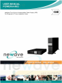
User Manual
1000-3000VA (single phase In/Output)
Intelligent True On-Line Uninterruptible Power Supply (UPS)
For Corporate & IT User Installation Guide
Intelligent True On-Line Uninterruptible Power Supply (UPS)
For Corporate & IT User Installation Guide
TABLE OF CONTENTS
1
Standard Unit Installation Guide
1.1
Important – Please read carefully prior to installation
1.2
Storage Instruction
2 Product Introduction
2.1
General Characteristics
2.2
Special Features
3 UPS Functional Descriptions
3.1
UPS Front Panel Display Descriptions
3.2
Real Panel Descriptions
3.3
Operating Modes & Voltage System Configurations
3.3.1 System Configuration Settings
3.3.2 Programmable outlet setting
4 Installation and Operation
4.1
Unpacking
4.2
Selecting Installation Position
4.3
Tower Configuration Setup
4.4
Rack-Mount Configuration Setup
4.5
Operation
4.5.1 Start Up in Normal AC Mode
4.5.2 Start-up in Battery Mode (Cold Start)
4.5.3 Shutdown
4.5.4 Self Testing during AC mode
4.5.5 Status & Alarm Buzzer
4.5.6 Battery Replacement
5
UPS Working Principle
5.1
UPS System Block Diagram
5.2
When Utility is Normal
5.3
When Utility is Abnormal/Absent
5.4
Overload Condition
5.5
Inverter Failure
5.6
Inverter/Internal Over temperature
5.7
Inverter Over-current and Inverter Output Voltage Out of tolerance
6 Maintenance Guide
6.1
Trouble Shooting
6.2
Error Codes and Their Descriptions
7 Bundle Software Installation Guide
7.1
Hardware Installation
7.2
WAVEMON Shutdown and Management Software
7.2.1 Why is UPS Management important?
7.2.2 Wavemon Shutdown and Monitoring Software
7.3
SNMP CARD/ADAPTER For Network Management /Remote Monitoring
8 Communication Port Explanation
8.1
True RS232 Port Descriptions
8.1.1 USB Port Descriptions
8.2
The Pin assignments of the EPO Input port are:
9 Optional Communication Cards
9.1
AS400 (Dry Contact) card
9.2
SNMP Cards
10 Battery Bank Installation
10.1 Chapter 1: Important Safety Instructions
10.2 Chapter 2: Introduction to the Front and Rear Panel
10.2.1
Front and Rear Panel Descriptions
4
4
4
5
5
5
6
6
7
8
8
9
10
10
11
12
14
16
16
16
16
17
17
18
20
20
21
21
22
23
23
23
24
24
26
26
26
27
27
27
29
30
30
31
31
31
31
32
33
33
34
34
10.3 Chapter 3: Installation and Operation
10.3.1
Unpacking
10.3.2
Selecting Installation Position
10.3.3
Installation Instructions
10.3.4
Rack Mount installation
10.3.5
Storage Instruction
10.3.6
Replacing the Battery
10.3.7
Specifications
10.3.8
Recycling the Used battery
11 Technical Specifications
35
35
36
37
39
42
42
43
44
45
1 Standard Unit Installation Guide
1.1 Important – Please read carefully prior to installation
1. Though this UPS is designed for easy Plug-and-Play installation, it is advisable to engage
qualified Electrical Engineer or trained technical personnel to commission or repair the UPS.
2. This UPS is equipped with an EMI filter. To prevent potential leakage current hazard, ensure that
the AC main supply is securely grounded.
3. To prevent any overheating of the UPS, keep all ventilation openings free from obstruction, and
do not place anything on top of the UPS. Keep the UPS rear panel 30 cm away from the wall or
other obstructions.
4. This UPS is designed to be installed and commissioned in a sheltered, controlled environment as
follows:
- Operating temperature 0-40°C and 30-90% non-condensing humidity
- Always avoid contact with direct sunlight
5. The UPS internal battery should be recharged every 2-3 months if not in use to prevent battery
self-discharge. The battery can be recharged when the UPS is connected to the utility supplì.
6. Always switch off the UPS and disconnect the batteries when relocating the UPS.
7. Please ensure that the input voltage of the UPS matches the utility supply voltage. Use a certified
input power cable with the correct plugs and sockets for the appropriate voltage system.
8. CAUTION -The Warranty of the UPS will be rendered void and the manufacturer reserves the
right to refuse replacement/compensation under the following conditions:
- Accidental damage to the UPS
- Installing the UPS in inflammable or hazardous environment.
- Improper installation or maintenance by unauthorised personnel
1.2 Storage Instruction
For extended storage in moderate climate, the batteries should be charged for 12 hours every 3
months interval by connecting the UPS to the utility supply and switch on input breaker located at
UPS rear panel. Repeat this procedure every 2 months if the storage ambient temperature is above
30°C.
2 Product Introduction
2.1 General Characteristics
1. True online technology continuously supplies your critical device with a stable, regulated,
transient-free pure sine wave AC Power.
2. High-efficiency PWM sine-wave topology yields an excellent overall performance. The high crest
factor of the inverter handles all high in-rush current loads without the need to upgrade the power
rating.
3. User-friendly Plug-and-Play design allows hassle-free installation. All units up to 3Kva are
supplied with input cables and output sockets as standard.
4. Built-in Maintenance-free sealed-type battery minimises the need for frequent after-sales service.
5. To protect the unit from overloading, the UPS will automatically switch to bypass mode in 30
seconds if loading is at 105%~ 120% of rated capacity. It will automatically switch back to inverter
mode once overload condition ceases.
6. Should the output becomes short-circuited, the UPS puts the system on stand-by mode, provide
visual & audible alarm, and cuts the output supply automatically till the short circuit situation is
resolved manually.
2.2 Special Features
1. High Frequency Transformer-less technology with rack/tower convertible enclosure enables the
UPS for integration even in the most difficult of environment with space constraints.
2. This UPS is equipped with fully digitalized control logic for greater functionality and enhanced
high level of power protection. Digital signal processing (DSP) also provides the UPS with
powerful communication capability, which enhances the flexibility for easy remote control and
monitoring
3. Wide input voltage tolerance from 120V~288V (220V version) allows under-voltage or overvoltage correction without unnecessary battery drain and helps extend the battery life span.
4. DC-start function ensures the start-up of UPS even during power outages.
5. Revolutionary battery management circuit analyzes battery discharging status to adjust battery
cut-off point and extend the batteries’ life span.
6. Active Power Factor Correction (PFC) control function constantly maintains the UPS Input Power
Factor (PF) at > 0.99 for superb energy efficiency.
7. Selectable Bypass input voltage tolerance (Sensitivity low/high) to prevent under or over voltage
being supply to the loads at Bypass mode. The selectable Voltage ranges are (i) Sensitivity Low :
184~260V & (ii) Sensitivity High : 194~260V.
8. Vast Selectable Output Voltages (200/208/220/230/240) to meet various voltage systems.
9. The UPS is designed to comply with various stringent international standards for Electromagnetic
Interference & protection (EMC).
3 UPS Functional Descriptions
3.1 UPS Front Panel Display Descriptions
Control Keypads
Symbols Functional Descriptions
1. ON
UPS Power-On Switch
2. OFF
UPS Power-Off Switch
3.Self-Test(Alarm Silence)
a. Command the UPS to perform self-testing
b. Alarm Silence To mute the alarm buzzer (Do not press & hold for > 1 sec)
LED Indicators
4. Normal Mode LED
5. Battery Mode LED
6. Bypass Mode LED
7. Overload LED
8. Fault LED
9. Site wiring fault LED
10.Battery Bad/Weak LED
11.Self Test LED
12.Outlet2 LED
13.Outlet1 LED
7 11 LEDs (% Indicating
Bars)
Symbols Functional Descriptions
LED illuminated indicates utility voltage within tolerance
(120Vac~280Vac)
LED illuminated indicates utility outage or out of tolerance,
loads supply by battery power
LED illuminated indicates bypass supply is normal
Red LED illuminated indicates UPS is overloaded
Red LED illuminated indicates fault or abnormal conditions
Red LED illuminated indicates Live & Neutral lines are
connected wrongly or High Neutral-Ground voltage
Red LED illuminated indicates low battery power or faulty
battery bank
Green LED illuminated indicates successful self-test and no
abnormal conditions or faults were found
Green LED illuminated indicates UPS Outlets 2 are
enabled and ready to supply loads
Green LED illuminated indicates UPS Outlets 1 are
enabled and ready to supply loads
a. During Normal Mode : Press and hold
for 1 sec,
the 7~11 LEDs will function as Load Rate indicators
showing 100%, 75%, 50%, 25% or 10% of UPS capacity
used. These LEDs will stop illuminating after 10 sec.
b. During Battery Mode : Press and hold
for 1
sec > the 7~11 LEDs will function as Battery Power
indicators showing 100%, 75%, 50%, 25% or 10% Battery
Power remaining. These LEDs will stop illuminating after 10
sec.
3.2 Real Panel Descriptions
1. USB Port
2. RS232 Port
3. Emergency Power Off (EPO) Dry Contact Signal inputs
4. Communication Card Options Slot
5. External Battery Connector
6. AC power connection socket
7. AC Outlets
8. Two programmable outlets
9. Utility Input fuse holder
10. Cooling Fans
1 1 . Output fuse holders
12. Output fuse holders for two programmable outlets
3.3 Operating Modes & Voltage System Configurations
Through the software that is delivered with the unit you can regulate the output voltage and the
power socket
3.3.1
System Configuration Settings
1. System:
2. Vo:
3.
4.
5.
6.
7.
8.
9.
Select Input Voltage 220V
Select UPS Output Voltage
200V/208V/220V/230V/240V/250V
UPS Modes :
Select Normal/CF50*/CF60* Mode
Fine turning of:
Output Voltage Regulation from 0 ±3%
Bypass Sensitivity:
Select Sensitivity Low/Sensitivity High**
Synchronizing:
Select 3Hz/1Hz Inverter Freq synchronizing range
KVA:
Key in 1 or 2 or 3 for the UPS KVA rating
Com Port:
Select Com Port to PC
Click on “Write” to confirm the configuration settings. The UPS will sound 2 “beeps” to
acknowledge setting is successful.
Note: *CF50/CF60 = Frequency Converter mode 50 to 60Hz or vice versa
**Sensitivity Low : 184~260V, High: 194~260V
3.3.2
Programmable outlet setting
The UPS is equipped with 2 programmable outlets for use to supply to less critical loads. These
outlets can be disabled to shed the less critical loads during back-up modes or overload
conditions to maintain quality power supply to the more critical loads connected to the UPS.
Click on the “Programmable outlet setting” bar to enter to the setting screen as shown below.
1. Outlet Turn On After Turn on UPS – select the time to automatically enable this outlet within the
specified time when the UPS is power on. If “0” sec is selected, the outlet will be enabled once
the UPS is power on.
2. Outlet Turn Off After AC Failure – select this option to automatically disable the outlet within the
specified time after utility outage to shed the less critical loads to provide longer battery back-up
time for the other more critical loads connected to the UPS.
3. Outlet Turn On After AC Recovered – select this option to automatically enable the outlet within
the specified time after the utility is restored.
4. Outlet Turn Off When Battery Lower than - select this option to automatically disable the outlet
at the specified remaining battery power capacity(%) during battery mode to shed the less
critical loads to prolong battery back-up time for the other more critical loads connected to the
UPS.
5. Outlet Turn Off When Overload – select this option to automatically disable the outlet during
overload condition (bypass mode) to possibly allow the more critical loads:
a) To be continually supplied via Bypass without shut down
b) To be transferred back to Inverter mode if the overload condition is removed by shedding
the less critical loads.
6. Click on “setting” to confirm the configurations. The UPS will sound 2 “beeps” to acknowledge
setting is successful.
7. Manual Control Switch – Click “On” or “Off” to manually enabled or disabled the programmable
outlets, overriding all previous settings.
4 Installation and Operation
Read the Safety Instruction guide (page 2 to 3) before installing the UPS
4.1 Unpacking
Inspect the UPS upon receipt. The manufacturer designed robust packaging for your product.
However, accidents and damage may occur during shipment. Notify the forwarder and dealer if there
is damage.
The packaging is recyclable; save it for reuse or dispose of it properly.
Remove the UPS from the carton box.
Check the package contents. Standard content shall includes:
1 set of User's Manual
2 pcs of IEC output cables (for UPS with IEC sockets only)
1 pc of AC Input Power Cord
1 set of UPS communication software with RS232 cable
1 set of Tower/Rack Accessories Kit as below:
Optiona
l
Optiona
l
4.2 Selecting Installation Position
The UPS is heavy. Select a location sturdy enough to handle the UPS weight.
To ensure proper operation and long operating life, always position the UPS according to the
following requirement:
1. Keep minimum 20cm (8 inches) distance clearance from
the rear panel of the UPS to avoid any obstructions.
2. Do not block the air-flow to the ventilation louvers of the
unit.
3. Please ensure the installation site is free from excessive
dust and the ambient temperature and humidity should be
within the specified limits.
4. Do not place the UPS in a dusty or corrosive environment
or near any flammable objects.
5. This UPS is not designed for outdoor use.
Relative humidity
(non condensation)
4.3 Tower Configuration Setup
Step 1
Step 2
Step 3
Step 4
4.4 Rack-Mount Configuration Setup
Step 3
Step 4
Step 5
Step 6
Step 7
4.5 Operation
4.5.1 Start Up in Normal AC Mode
1. Before commencing the installation, please ensure the grounding is connected properly.
2. Ensure the voltage of Utility matches with the input voltage window of the UPS.
3. Connect UPS main power cord into Utility AC power source receptacle.
4. Switch on the AC power source, all the LEDs on the front panel display will flash once after 3
seconds, except
which will remain illuminated (Green). At the same time, the fan at
the rear of the UPS will start operating.
5. Press the
Switch for approximately 3 seconds to start the UPS, the buzzer will beep and
the LED display of
and
will light up after 30 seconds. The start-up procedure is
completed and the UPS outlets are ready to supply to load.
6. It is advisable to perform a battery mode test before connecting the loads to the UPS to ensure
the batteries are working properly.
Switch Off the AC power source when the UPS had been switched on. The
LED on the front
panel display will light off while the
LED will be illuminated and the buzzer alarm will beep
intermediately, indicating the UPS is in Battery Mode.
Connect a non critical load to the UPS outlets to confirm if the Battery is supplying power.
Repeat the test by switching on & off the AC power source to ensure the UPS is functioning
properly
4.5.2
Start-up in Battery Mode (Cold Start)
This UPS is able to be Switch On for operation without the presence of an AC power source.
Press and hold the
Switch until the buzzer beep, within the next 10 sec press and hold the
Switch for
time. The UPS shall perform its start-up procedure. The LED display of
and
will light up after 30 seconds, the buzzer will beep intermediately to indicate
successful power on.
Note:
Ensure the UPS Battery is pre-charge for minimum 4 hours by simply connecting the AC power cord to the
Utility receptacle.
If the Battery Voltage is below the preset value (1Kva = 33.5V; 2Kva/3Kva = 67V) the UPS
will not be able to start up in Battery Mode.
4.5.3
Shutdown
Shutdown in AC Mode:Press the
Switch for approximate 5 seconds until the buzzer beeps, the UPS will stop
power supply to the outlets.
LEDs shall remains illuminated and the ventilating fans
shall continue to operate. Switch Off the AC power source, after 10 sec the
LEDs will
light off and the ventilating fans stop operating. The UPS is now completely shutdown.
Shutdown in DC Mode:Press the
Switch for approximate 5 seconds until the buzzer beeps. The UPS will stop
power supply to the outlets,
LEDs light off and the ventilating fans shall stop to
operate after 10 sec. The UPS is now completely shutdown.
4.5.4
Self Testing during AC mode
After the UPS has been successfully start-up in AC mode, press the
Switch for
approximately 5 seconds until the buzzer beeps. The
LED will blink to indicate self test in
progress. The
LED will stop blinking and remains illuminated when the self test is completed
without finding any faults or abnormal conditions. The
LED will automatically lights off 30 sec
after the successful self test.
4.5.5
Status & Alarm Buzzer
The following table helps to define some of the common UPS statuses
with respect to their buzzer beep descriptions.
Status Definitions
UPS faulty, Inverter
shutdown. All
functions inhabited.
UPS faulty, loads
continue to be
supplied via Inverter
or Bypass.
battery mode
battery low
confirm/RS232 port
receiving
service mode ok
UPS initial starts up
with self test
Buzzer Beep Descriptions
Long Continuous Beep
Single successive beep with ~ 2 sec
interval
Single short successive beep with ~1
sec interval
Very quick and short successive
beep
2 quick & short beeps
1 quick & short beep
2 successive quick & short beeps,
repeating per ~2 sec interval.
4.5.6
Step 1
Step 2
Step 3
Battery Replacement
Step 4
5 UPS Working Principle
5.1 UPS System Block Diagram
Figure 5.1 above illustrates the True On-Line Double Conversion architecture of the UPS
system. The major modules consist of:
1) An AC to DC power converter (Rectifier) with PFC control circuit
2) A DC to AC power high frequency inverter
3) An Intelligent Battery Charger
4) A bank of stationary maintenance-free batteries
5) A DC to DC push/pull converter control circuit
6) A Static Bypass Loop
7) Input & Output EMI Filter
The table below provide a summery guide to the UPS operating modes against the Utility AC
Power Source conditions
Utility
Conditions
Utility Normal
Utility Abnormal
(under or over
voltage) / Absent
Utility
Abnormal/Absent,
Battery low voltage
UPS Operating Modes
Rectifier convert AC to DC, battery
charging, Inverter convert DC to AC
and supply to loads with clean & stable
power.
Rectifier and charger stop
operating Battery discharge via
DC~DC push/pull circuit and supply to
Inverter. Loads continue to receive
supply from Inverter. Alarm buzzer
beeps, UPS now on battery mode.
Rectifier and charger stop
operating Battery discharge via
DC~DC push/pull circuit and supply to
Inverter. Alarm buzzer beeps with quick
& short succession, indicating battery
power low and Inverter may stop supply
soon.
LEDs Display
indications
LEDs
remain illuminated
LED off,
illuminated
LED off,
(Battery Low)
illuminated.
LED
LED
Paragraph 5.2 ~ 5.7 below provide detailed descriptions of the UPS operating principle
5.2 When Utility is Normal
The working principle of the UPS under Utility normal condition is illustrated as follows:
Fig 5.2
When Utility is normal, the AC source is rectified to DC, partially fed into the charger to charge
battery and partially fed into irter. The inverter revert the DC to a cleaned and pure AC to supply
energy to the load connected. The
LEDs illuminated.
5.3 When Utility is Abnormal/Absent
The working principle of the UPS under Utility abnormal condition is illustrated as follows:
Fig 5.3
1. When Utility is abnormal, the UPS will direct the battery energy automatically to the Inverter
without delay, and turn off the charger and AC/DC converter. The inverter revert DC to AC to
supply energy to the output load connected without interruption. The
LED will be illuminated.
2. When Utility is back to Normal, the UPS will turn on the AC/DC converter, turn off DC/DC
converter and switch the charger to charging mode. It has the same working principle as figure
5.1.
3. During a utility outage, the UPS will work as illustrated in figure 5.2. When Battery is low,
buzzer will beep continuously till battery is completely cut off. The battery low protection of the
UPS will cut off battery supply after a preset threshold to avoid the battery from over-drain. The
(Battery Low) LEDs will light up till the UPS is completely cut off. The UPS will re-start
automatically when Utility is available.
5.4 Overload Condition
The working principle of the UPS when overloading is illustrated as follows:
Fig 5.4 i-
1. Generally modern day electronics & IT equipment generate an inrush current when switching
on. The amount of inrush current varies from equipment to equipment, some can be as high as
6 times its rated capacity while others produce negligible inrush. To prevent severe damage to
its Inverter cause by the inrush produce by the loads, the UPS is equipped with electronics
overload protection feature as standard. If the UPS loading is >105~120% of its capacity, it will
switch to bypass mode in 30 seconds to protect the Inverter. If overload condition is eliminated
by reducing the load to <105%, the UPS will switch back to Inverter mode automatically. If the
UPS is over 150% loading, it inverter will shutdown immediately.
2. The UPS Bypass loop is also equipped with overload protection. Its overload capacity is
illustrated by the graph & table below.
(sec)
(Load %)
Load(%)
uo~iza
121-Ш
131-135
136-145
146-143
149-157
158-176
177-1S7
1S8<
250
125
50
30
s
i
>
0.32
0.16
Delay Time
(Set)
5.5 Inverter Failure
Output Load short circuit when supply via inverter
If output load is short circuited while supply via Inverter, the UPS will shutdown Inverter
automatically and stop supply to the loads. The Fault LED lights up and the buzzer will beep
continuously. The UPS will not switch on automatically after short circuit condition is eliminated.
The UPS has to be re-start manually (refer to 4.5.1 ‘Start Up in Normal AC Mode’).
Fig 5.5
Output Short circuit when supply via bypass loop
If output load is short circuited under bypass mode, the input AC fuse/breaker will be activated
(open circuited) to prevent the output load from damage. You shall replace a new fuse with same
rating after the short circuit condition is eliminated.
5.6 Inverter/Internal Over temperature
If the UPS experiences internal over-temperature when Utility is normal, it will switch to bypass
loop. The UPS will switch back to inverter mode when the over-temperature situation is eliminated.
If over temperature occurs when Utility is abnormal, the buzzer will beep continuously and the Fault
LED
will light up. The UPS will cut off supply to the loads.
5.7 Inverter Over-current and Inverter Output Voltage Out of tolerance
If the UPS inverter delivers over-current and out-of-tolerance voltage to its outlets, the UPS is out
of order. The UPS will switch to bypass loop when Utility is normal. The Utility
LED, Bypass
LED and Fault
LED will light up.
If these two fault conditions occur when Utility is abnormal, the UPS will cut off the supply to its
outlets and the Fault
LED will light up.
6 Maintenance Guide
6.1 Trouble Shooting
When the UPS becomes faulty or malfunctions during operation, you may check the fault lists
below for respective solutions. Should the problem persists, please contact your local dealer for
assistance.
Situation
UPS Fault
Check Items
Solution
LED
Read the error code (see 1.Er05, Er25,
next page for error
readings) displayed by
the combinations of the
LEDs and verify the fault
as follow:
1. Check battery connection if is properly done. Measure Battery voltage
to ensure batteries are charged or healthy. Recharge batteries for 8
hours if necessary. Simulate Utility outage to verify if UPS is able to
provide DC back-up. Otherwise consult your local dealer right away.
2. Overload
2. Disconnect some non critical loads form the UPS output until overload
ceases. Check if there is any short circuit between cables due to
broken cable insulator. Replace the cables in necessary.
3.Er11 (UPS Over
Temperature)
3. Remove any objects obstructing the ventilation louvers. Verify if the
cooling fans are working properly. Contacts your local dealer to
replace the fans if necessary.
4.Site wiring/Ground fault
4. Verify if the “L” & “N” phase of the Utility AC source has been wrongly
wired or if the Ground-Neutral Voltage exceeded the limits
5.Er14 (Fans out of order) 5. Verify if the ventilating fans are functioning properly. Do not attempt to
replace the fans by yourself. Contact your local dealer for replacement.
6.Other error codes
UPS fails to provide
battery backup or its
back up time is
shorter than its
intended
performance.
UPS is normal but
Check if all power
no Output to load
codes are properly
connected.
6. Consult your local dealer for assistance.
If the backup time remains non-satisfactory after 8 hours of
charging, please contact your local dealer for battery
replacement.
If problem persist, consult your local dealer for technical
assistance.
Situation
The UPS switches to
battery mode then
back to Utility mode,
when connected
device is turned on.
Or, the UPS
switches back and
forth between battery
and Utility.
Strange noise and
smell
UPS is unable to
provide backup
power source
Check Items
Solution
if any power strip is 1.
Do not use power strip.
connected
2.
Replace the wall
to the UPS.
receptacle/cable cord plug.
Verify if there is any
damage to the utility
Wall Receptacle or if
the cable cord plug is
faulty.
Immediately shut down the whole
System. Disconnect the power from
the UPS and call for service.
Check that the battery connectors are
fully engaged. Allow the battery to
recharge if the batter is weak. If
problem persist after recharging,
replace the battery. If problem persist,
consult your local dealer for technical
assistance.
Note When the Fault LED
is illuminated, press and hold the
key to check the error code.
The error code is represented by the five 10% 100% bar LEDs. Each bar LED represents a
number as shown in the figure below.
For example, the fig. below showed the 100% bar LED, 75% bar LED & illuminated when the
key is pressed. The error code shall be 1 + 2 + 8 = 1 1 , or Er11, which indicate that the UPS is overtemperature.
6.2 Error Codes and Their Descriptions
Code
Descriptions
Er05
Battery weak or faulty
Er06
Output short-circuited
Er07
EPO mode
Er11
UPS over-temperature
Er12
Inverter overload
Er14
Fans out of order
Er18
EEPROM's data error
Utility Low <85/170V & Battery
Disconnect
Bypass overload
EEPROM's data not conform to the Jumper
Setting
Er24
Er28
Er31
7 Bundle Software Installation Guide
7.1 Hardware Installation
1.
2.
3.
Connect the male connector of RS232/USB* cable to the UPS communication port.
Connect the female connector of the RS232/USB* cable to a dedicated RS232 port of the
Computer.
For optional interface cards, please refer to Chapter 9 for more details.
*Note: Only RS232 cable is provided with the UPS. USB cable is optional
7.2 WAVEMON Shutdown and Management Software
7.2.1 Why is UPS Management important?
By combining a UPS with network management products, such as an SNMP protocol, Systemadministrators are guaranteed their data and their system will constantly be protected from
corruption or data loss even in the event of an extended power failure or when batteries reach a
critical low state. In the event of a power disturbance system administrators can also monitor their
network from a central location, allowing an early detection of problems. In fact utility power is
unreliable at times, ensuring that all network systems have constant power can be a difficult task.
The situation becomes even more complex if systems are managed across a Local Area Network
(LAN) or Wide Area Network (WAN) around the world.
When a power failure occurs action can be taken to protect the system and its valuable data. If no
action is initiated by the operator, this event can seriously damage the system. The UPS software
will react automatically in such a case and shutdown the operating system. NEWAVE has found it
important to have a complete solution for its UPS and is able to offer a wide range of
monitoring/remote controls for assuring the maximum protection degree to the NEWAVE
customers.
7.2.2 Wavemon Shutdown and Monitoring Software
Wavemon is an external monitoring and shutdown software which was designed to operate with all
NEWAVE UPS products, both with the DRY PORT (Relays) X1-X21 and SMART PORT (RS232) JD1.
The software packet consists of a CD ROM for most diffused operating systems (Windows, Unix,
OS/2, DEC VMS, Novell, Apple), a standard connection and a user manual.
The 25 pin port with voltage-free contacts may also be used for automatic shutdown in connection
with wavemon. It is necessary to provide a special cable to connect the 25 pin port of the UPS and
the serial port of the server.
Figure 7.5. Monitoring image.
The main characteristics of wavemon software are:
•
•
•
•
•
•
Automatic unattended master/slave shutdown in heterogeneous networks
On-screen autonomy time / battery time countdown
On-screen server log off and shutdown procedure
Extensive logging of all UPS activity and power quality data, with timestamp
Scheduled UPS economy mode, service mode, other systems status
Graphical user interface for Windows compatible platforms
•
•
•
Automatic unattended local shutdown
Special software modules to close and save open MS-Office documents.
Compatible for all optional modules like UPSDIALER, SNMP adapters,
Temperature sensors, etc.The UPS-Management Software is a client-/serverapplication for networks and local workstations. Basically Wavemon consists of two parts: the
server-module of the UPS-Management Software is UPSMAN, which communicates via RS-232
cable with the UPS. Working as a background process the UPSMAN collects messages, received
from the UPS. The UPSMAN interprets received messages and makes them available to the clientmodule UPSMON and to any SNMP-based management station.
When UPSMAN detects voltage variations or a power failure it can execute various so called
system „event routines“, which for example may shutdown the server or send warning to connected
users. These system event routines which are a part of the UPS-Management Software can be
adjusted to your demands.
The UPS management software includes with every serial number the licence for using the UPS
service on one server with one UPS and an unlimited numbers of connected WINDOWS
workstations. When operating with two or more servers a licence for every additional server is
required. It doesn’t matter if the UPS service runs at that location or if the server is halted by a UPS
service via remote command. The same regulations are applicable to the use of remote
send/receive modules RCCMD and multiserver shutdown under NT, UNIX and other operating
systems. The service programs are generally delivered as a single-licence. To use a single CD
ROM to shutdown multiple servers you have to purchase additional CD license keys.
Parallel/redundant UPS systems are also manageable by the software.
The main principle is: let introduce a shutdown of a Server only when strictly necessary. A correct
Parallel Handling has therefore to manage a parallel system as a whole and always considering
redundancy. Following statements apply:
-
Every alarm on any unit is immediately notified, but …
… a reaction to a severe fault is introduced only when the minimum number of UPS –Modules
necessary to supply the load exhibits an alarming situation.
The real Battery autonomy time of the (whole) parallel system is computed continuously.
Maintenance on a redundant unit may be executed without annoyance to the management system
(supervisor).
In order to be managed, a NEWAVE UPS can be integrated into a network in two ways:
1. By means of the server which is being powered by the UPS and is integrated in the network. In
most of the cases the server is used as sub-agent and you only need the Wavemon software
without any SNMP Adapter. You need a standard serial connection between the RS232 SMART
port of the UPS and the RS232 port of the computer/server.
2. In some situations it is preferable to interface the network via an SNMP adapter. By this way up
to 50 computers can be shut down in a RCCMD environment. RCCMD (Remote Console
Command) is an additional software module, which can be triggered by the SNMP device to
executes a command (typically a shutdown command) on a remote system.
7.3 SNMP CARD/ADAPTER For Network Management /Remote Monitoring
The Simple Network Management Protocol (SNMP) is a worldwide-standardized communicationprotocol. It is used to monitor any device in the network via simple control language. The UPSManagement Software also provides its data in this SNMP format with its internal software agent.
The operating system you are using must support the SNMP protocol. We offer our software with
SNMP functionality for Novell, OS/2, all Windows running on INTEL and ALPHA, DEC VMS,
Apple.
Two types of SNMP interfaces with identical functionality are available: an external SNMP-Adapter
(Box) and an internal SNMP-Card. Both can manage a parallel system (N modules) and return
either global values - which are consistent for the whole parallel system - or specific values from
the single modules.
UPS
External SNMP-Adapter
Internal SNMP-Card
Figure 7.6 SNMP Adapter
The adapter may be configured via Telnet, HTTP (Web-Browser) or serial connection (Terminal).
For normal operation at least one network connection (Ethernet) is required.
The SNMP adapter can be used, utilising the RCCMD send function, for an automatic network wide
shut down or just for informing connected users. The shut down procedure can be initiated on a low
residual battery autonomy time (downtime) or by a countdown timer which is started at the
beginning of the alarm. A shut down is therefore possible without extra input from the operator, and
is fully software controlled.
The small (125x70 mm) External SNMP adapter comes with following interfaces:
1.
2.
3.
4.
5.
6.
7.
RJ-45 connector for 10/100 Base-T(autoswitchable)
Serial Port for configuration (COM2) or optional ModBus interface.
Error/Link LED for UPS status
Aux Port
DIP Switch
Serial Port to the UPS (COM1)
DC Supply (9 VDC or 9-36 VDC supply, depending on model);
Figure 7.7 External SNMP Adapter
The Internal SNMP-Card can be inserted into an appropriate
extension slot of the UPS PowerVario. This adapter communicates
via the serial port of the UPS and makes a direct multiple server shut
down possible without additional SNMP management software.
Figure 7.8 Internal SNMP Adapter
For detailed information please see Software Manual provided with the WAVEMON CD ROM.
RCCMD - Remote Console Command module for a multi-server shutdown. This stand-alone
software module is designed to receive and execute a command issued by a remote device. Thanks
to RCCMD it is possible to execute a shutdown in an heterogeneous multiplatform network. The new
release RCCMD2 is an application available for all Operating Systems, analogous to Wavemon. Our
SNMP Interfaces are compatible to RCCMD
8 Communication Port Explanation
The UPS is equip with EPO dry contacts input, true RS232 & USB Communication port as
standard to provide communication with bundled UPS monitoring software for remote monitoring
of UPS status via PC.
There are 2 other optional interface cards available to meet various communication needs, i.e.
dry contact relay card and SNMP/WEB card
The bundled software of the UPS is compatible with many operating systems such as Windows
98, & 2000, ME, NT and XP. For other applications such as Novell, NetWare, Unix, Linux, please
contact your local dealer for suitable software.
All the communication ports (including optional cards) can be active & use simultaneously to
monitor the UPS status. However only 1 communication interface at any one time with the
highest priority has the ability to command & control the UPS. The priority of these
communication interfaces are as follow:
Highest Priority (in descending order),
1) EPO input port
2) Optional Interface card
3) USB
4) RS232
8.1 True RS232 Port Descriptions
The RS232 interface shall be set as follows:
Baud Rate
2400 bps
Data Length
8 bits
Stop Bit
1 bit
Parity
None
The Pin Assignments of the true RS232 port are illustrated as follows:
Pin 3: RS232 Rx
Pin 2: RS232 Tx
Pin 5: Ground
8.1.1
USB Port Descriptions
The USB communication protocol definition as below:
1. Comply with USB version 1.0, 1.5Mbps
2. Comply with USB HID Version 1.0.
3. The Pin Assignments of the USB port:
8.2 The Pin assignments of the EPO Input port are:
To enable the EPO function, please short Pin 1 & 2.
9 Optional Communication Cards
The UPS rear panel is equipped with a ready “plug-and-play” optional
communication card slot to accommodate either a AS400 Dry Contact card or
SNMP/Web card. These optional communication cards respective functions are
described in 9.1 & 7.3
9.1 AS400 (Dry Contact) card
The signal descriptions of the 10 assigned pins of the Dry contact card are indicated below. Take
note that all pins except Pin-9 & Pin-10 which are isolated, are shorted or open circuited (selectable
using Jumper cable) to the common Pin-8
The pin assignments of the 10-Pin Terminals:
Pin 1: UPS on Bypass mode.
Pin 2: AC abnormal
Pin 3: AC normal
Pin 4: Inverter On
Pin 5: Battery Low
Pin 6: Battery weak or faulty
Pin 7: UPS fault Alarm
Pin 8: Common
*Pin 9: Shutdown UPS positive (+) signal
*Pin 10: Shutdown UPS negative (-) signal
* To Shutdown the UPS, supply a DC voltage of between 5.5V~25V to Pin-9 (use as “+”
terminal) and Pin-10 (use as “-“ terminal).
9.2 SNMP Cards
Both SNMP cards produce by UIS Abler and Megatec are suitable to use with this UPS. Please
refer to the soft copy user manual which come with each respective cards for installation guide.
SNMP card By UIS Abler
SNMP card By Megatec
10 Battery Bank Installation
10.1 Chapter 1: Important Safety Instructions
SAVE THESE INSTRUCTIONS
This manual contains important instructions that should be followed during installation and maintenance
of the battery bank and batteries.
An Important Notice
•
The battery bank which is supplied with a factory input plug can be safely connected to the wall receptacle
by the user.
•
This battery bank is connected to an UPS. There will be voltage at the output terminals if the UPS is turned
on even if the input AC Mains is not available.
•
Make sure that the AC Utility outlet is correctly grounded.
•
Do not try to repair the unit yourself, contact your local supplier or your warranty will be void.
•
Use a certified input power cable with the correct plugs and sockets for the appropriate voltage system.
•
To eliminate any overheating of the battery bank, keep all ventilation openings free from obstruction and do
not place any foreign objects on top of the battery bank. Keep the battery bank 20 cm away from the wall.
•
Make sure the battery bank is installed within the proper environment as specified. (0-40°C and 30-90%
non-condensing humidity)
•
Do not install the battery bank under direct sunlight. Your warranty will be void if the batteries fail due to
overheating.
•
This battery bank is designed for indoor use only.
•
This battery bank is not designed for use in dusty, corrosive and salty environment .
•
The warranty for this battery bank will be void if water or other liquid is spilt or poured directly onto the
battery bank. Similarly we do not warrant any damage to the battery bank if foreign objects are deliberately
or accidentally inserted into the battery bank enclosure.
•
The battery will discharge naturally if the system is unused for a period of time.
•
It should be recharged every 2-3 months if unused. If this is not done, then the warranty will be null and
void. During normal operation, the batteries will be automatically remained in charged condition.
•
Servicing of Batteries Should be Performed or Supervised by Trained Personnel with Knowledge of
Batteries and the Required Precautions
•
When Replacing Batteries, Replace With the Same Quantity, Type & Capacity.
•
CAUTION – Do Not Dispose of Battery or Batteries in an open fire. The Battery May Explode.
•
CAUTION – Do not open or mutilate the batteries. The electrolyte from the batteries is toxic and harmful to
the skin and eyes.
•
CAUTION – Risk of Electric Shock – Battery Circuit is not isolated from AC, hazardous Voltage may exist
between battery terminals and ground. Test before touching with bare hands.
•
CAUTION – A Battery can present a Risk of Electrical Shock and High Short Circuit Current. The
Following Precaution Should be Observed When Working on Batteries:
A)
Remove watches, rings, or other metal objects.
B)
Use tools with insulated handles.
C)
Wear rubber gloves and boots.
D)
Do not lay tools or metal parts on top of batteries.
E)
Disconnect charging source prior to connecting or disconnecting battery terminals
10.2 Chapter 2: Introduction to the Front and Rear Panel
10.2.1 Front and Rear Panel Descriptions
To replace batteries, please remove the
screw
covers and the screws inside the covers.
To the DC terminal of the 2nd(or next) battery
2. EXT.BAT. +/- bank
connected.
To the UPS DC terminal or the next battery
3. UPS BAT. +/bank.
1. Battery Over-current Protection Breaker
2. To easy swappable battery, please put the
position of the breaker in “O” position. In
case there is 2nd(or next) battery bank
4. DC Breaker
connected with the battery bank, the DC
voltage from the UPS Bat.+/- will flow
through without any interruption to
the 2 nd Battery Bank.
1.Screw Cover
10.3 Chapter 3: Installation and Operation
Note: The packing condition and the external outlook of the unit should be inspected carefully
before installation. Retain the packing material for future use.
10.3.1 Unpacking
1. Take the battery bank out of the PE foam.
2. Remove the packing materials.
Note: The battery bank module is approx. 12.5~50 kgs, be cautious when unpacking and lifting
the unit to avoid injury
3. Standard Package includes User's Manual
4. Accessories for Tower and Rack Mount
10.3.2 Selecting Installation Position
It is necessary to select a proper environment to install the unit, in order to minimize the possibility of
damage to the battery bank and extend the life of the batteries. Please follow the instructions below:
1. Keep at least 20cm(8 inches)
clearance from the rear panel
of the battery bank from the
wall or other obstructions.
2. Do not block the air-flow to the
ventilation openings of the
unit.
3. Please ensure the installation
site environmental conditions
are in accordance with the
battery bank working
specifications to avoid
overheat and excessive
moisture.
4. Do not place the battery bank in a dusty or corrosive
environment or near any flammable objects.
5. This battery bank is not designed for outdoor use.
Relative humidity
(non condensation)
10.3.3 Installation Instructions
Tower installation
Stand alone unit
Step 1
Step 2
Use with UPS
Step 1
Step 2
10.3.4 Rack Mount installation
Step 1
Step 2
Step 3
Step 4
Connect DC Cable
Second Battery
First Battery Bank
UPS
10.3.5 Storage Instruction
For extended storage through moderate climate(-15 to +30 °C / +5 to +86 °F), the batteries should be
charged for 12 hours every 6 months by plugging the UPS power cord into the wall receptacle.
Repeat this every 3 months under high temperature (+30 to +45 °C / +86 to +113 °F) environment.
10.3.6 Replacing the Battery
Step 1
Step 2
Step 3
Step 4
10.3.7 Specifications
10.3.8 Recycling the Used battery
Contact your local recycling or hazardous waste center for information on proper disposal of
the used battery.
11 Technical Specifications
TECHNICAL SPECIFICATIONS
POWERVARIO
Intelligent True On-Line Uninterruptible Power Supply (UPS)
For Corporate & IT User Installation Guide
TABLE OF CONTENTS
1
Specifications
1.1
VA Rating
1.2
Input
1.3
Output
1.4
Battery System
1.5
Transfer Time
1.6
Front Panel
1.7
Protection
1.8
Audible Alarm
1.9
Physical
1.10
Environmental
1.11 Interface
1.12
Standards and Certification
3
3
3
3
4
4
4
4
5
5
5
5
6
1 Specifications
1.1 VA Rating
Model
Apparent Output Power
Active Output Power
Power Factor
Topology
Type
Agency Approvals
PVO1000
1000VA
700Watts
PVO2000
2000VA
1400Watts
0.7
Double conversion On-Line
Rack/Tower
CE
PVO3000
3000VA
2100Watts
1.2 Input
Model
Voltage Window
Voltage
Range
Low Line
Transfer
Low Line
Comeback
High Line
Transfer
High Line
Comeback
PVO1000
230V
PVO2000
120/140/160 - 288Vac
Base on load percentage (0~33/33~66/66~100%)
230V
120/140/160Vac
230V
170Vac
230V
288Vac
230V
278Vac
Frequency
Phase
PF
Typical Transfer Time
PVO3000
50/60 Hz auto-select, ± 5Hz
Single phase with ground
0.99 at full rated linear load
0 ms.
AC Leakage current
230V
Surge Protection
230V
3.5mA
300 joules
1.3 Output
Model
Output
(INV.
mode)
Voltage
230V
Voltage Regulation
Frequency(Synchronized Range)
Frequency(Battery Mode)
Current Crest Factor
Harmonic Distortion
Transient Response(ms)
Waveform
To AC Mode (Full load)
Efficiency
To Battery Mode (Full load)
PVO1000
PVO2000
PVO3000
230V,adjustable to 200/208/220/230/240
<± 1% until low battery warning
3Hz or 1Hz (setting by software)
±0.1% (0.05~0.06Hz) unless synchronized to line
3:1
3% THD(Linear Load)
7% THD(Non-Linear Load)
60ms/5%
Pure Sine wave
85%
85%
88%
83%
83%
85%
1.4 Battery System
Model
Type
Numbers of Batteries
Backup Time(Full Load)
Recharging Time
Charging Current (Max.)
Charging Voltage
Hot Swappable Battery
Internal battery
DC leakage current
Battery type
PVO1000
12V/7.2Ah
3
>7min.
PVO2000
PVO3000
12V/7.2Ah
12V/9Ah
6
6
>7min.
>5min.
4 Hours to 90%
1.1A
2.16A
2.7A
41.0Vdc±0.5V
82.0Vdc±0.5V
82.0Vdc±0.5V
Yes
Yes
30uA (±10uA) with no AC applied and the unit in the off position
Sealed, non-spillage, maintenance-free, lead acid
1.5 Transfer Time
Model
AC to DC
Inverter to Bypass
DC Start
Self Diagnostics
PVO1000
2.5ms(Typical)
PVO2000
Zero
PVO3000
Zero
Yes
Upon Power-on and Software Control
1.6 Front Panel
Model
LED
Key
PVO1000
PVO2000
PVO3000
Load Level/Battery Level/ Battery Mode/ Normal Mode/Bypass Mode/ SelfTest/ Weak/Bad Battery/Site Wiring Fault/ Fault/ Overload/Programmable
Outlet1//Programmable Outlet2
ON Button/ OFF Button/ (Test/Alarm Reset Button)
1.7 Protection
Model
Overload
PVO1000
PVO2000
(AC Mode )
105 continuous
106 120 for 30 seconds transfer to bypass
121 150 for 10 seconds transfer to bypass
150
for immediately transfer to bypass
Buzzer continuously alarms.
(Battery Mode)
105 continuous
106 120 for 30 seconds shuts down
121 150 for 10 seconds shuts down
150
for immediately shuts down
Buzzer continuously alarms.
PVO3000
(Bypass Mode)
105 continuous
106 120 for 250 seconds shuts down
121 130 for 125 seconds shuts down
131 135 for 50 seconds shuts down
136 145 for 20 seconds shuts down
146 148 for 5 seconds shuts down
149 157 for 2 seconds shuts down
158 176 for 1 seconds shuts down
177 187 for 0.32 seconds shuts down
188
for 0.16 seconds shuts down
Buzzer continuously alarms.
Bypass mode : Input Fuse/Input Breaker
Normal Mode: Output Breaker/Electronic Circuit
Battery Mode: Output Breaker/Electronic Circuit
ABDM
UPS shuts down immediately
Short Circuit
Battery
EPO
Over
Temperature
Transfer to Bypass
Mode
UPS shuts down
immediately
Transfer to Bypass Mode
UPS shuts down immediately
1.8 Audible Alarm
Model
Battery Mode
Low Battery
Overload
Fault
PVO1000
PVO2000
PVO3000
Sounding once every 1.5 seconds
Sounding once every 0.2 seconds
Sounding once every 3 second
Continuously Sounding or Sounding once every 3 second
1.9 Physical
Model
Dimensions(HxWxD in mm)
Weights
Input Connection
230V
Output Connection
230V
PVO1000
88(2U)x440(17”)x405
34.5Ib(15.7kg)
10A, IEC 320-C14
PVO2000
88(2U)x440(17”)x650
64.7Ib(29.4kg)
10A, IEC 320-C14
(6) 10A,IEC 320-C13
PVO3000
88.8(2U)x440(17”)x650
65.3Ib(29.7kg)
16A, IEC 320-C20
(4) 10A,IEC 320-C13
(1) 16A,IEC 320-C19
1.10 Environmental
Model
Operation Temperature
Noise Level
Relative Humidity
PVO1000
PVO2000
0-40
50dBA
0 to 90% (Without condensation)
PVO3000
1.11 Interface
Model
Interface Type
SNMP(option)
Compatible platforms
PVO1000
PVO2000
PVO3000
1 *USB port+ 1*RS-232 port
Power management from SNMP manager and Web browser
Windows Unix, OS/2, Novell, Apple
1.12 Standards and Certification
Model
Safety
Performance
EMC
Markings
PVO1000
PVO2000
PVO3000
IEC/EN 62040-1-1,IEC 60950-1
IEC/EN 62040-3
EN50091-2/IEC 62040-2 class A
IEC 61000-4-2/-3/-4/-6-8/-11,IEC 61000-3-2/-3
CE, cUL, FCC additional versions on request