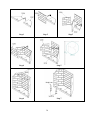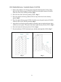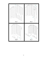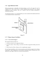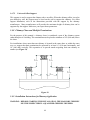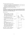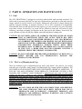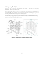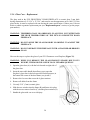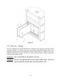
1
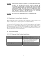
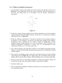
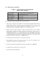
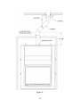
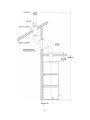
Installation and Operation Manual FP11 FRONTENAC Qualified Clean Burning Decorative Fireplace U.S. EPA Low Mass Wood-burning Fireplace voluntary program phase 2 emission level qualified model Safety tested according to ULC S610 and UL 127 Standards by www.valcourtinc.com READ AND KEEP THIS MANUAL FOR REFERENCE This manual is available for free download on the manufacturer’s web site. It is a copyrighted document. Re-sale is strictly prohibited. The manufacturer may update this manual from time to time and cannot be responsible for problems, injuries, or damages arising out of the use of information contained in any manual obtained from unauthorized sources. Printed in Canada 45543A 04-12-2012 THANK YOU FOR CHOOSING THIS VALCOURT FIREPLACE As one of North America’s largest and most respected wood stove and fireplace manufacturers, VALCOURT takes pride in the quality and performance of all its products. We want to help you get maximum satisfaction as you use this product. In the pages that follow you will find general advice on wood heating, detailed instructions for safe and effective installation, and guidance on how to get the best performance from this fireplace as you build and maintain fires, and maintain your wood heating system. We recommend that our woodburning hearth products be installed and serviced by professionals who are certified in the United States by NFI (National Fireplace Institute®) or in Canada by WETT (Wood Energy Technical Training) or in Quebec by APC (Association des Professionnels du Chauffage). Congratulations on making a wise purchase. Read this entire manual before you install and use your new fireplace. It is important that you follow the installations guidelines exactly. Failure to install this fireplace correctly could result in a house fire, bodily injury or even death. You may need to obtain a building permit for the installation of this fireplace and the chimney that it is connected to. Consult your municipal building or fire department about installation requirements in your area. We recommend that you also inform your home insurance company to find out if the installation will affect your policy. PLEASE NOTE THAT THE PICTURES SHOWN IN THIS MANUAL ARE GENERIC AND MAY NOT MATCH EXACTLY THE LOOK OF YOUR FIREPLACE. WARNING: THE INFORMATION GIVEN ON THE CERTIFICATION LABEL AFFIXED TO THE APPLIANCE ALWAYS OVERRIDES THE INFORMATION PUBLISHED, IN ANY OTHER MEDIA (OWNER’S MANUAL, CATALOGUES, FLYERS, MAGAZINES AND/OR WEB SITES). CAUTION: DO NOT ATTEMPT TO MODIFY OR ALTER THE CONSTRUCTION OF THE FIREPLACE OR ITS COMPONENTS. ANY MODIFICATION OR ALTERATION OF CONSTRUCTION MAY VOID THE WARRANTY, LISTINGS AND APPROVALS OF THIS SYSTEM. IN THAT CASE, STOVE BUILDER INTERNATIONAL (SBI) WILL NOT BE RESPONSIBLE FOR DAMAGES. INSTALL THE FIREPLACE ONLY AS DESCRIBED IN THESE INSTRUCTIONS. 2 1 PART A – INSTALLATION ....................................................................... 5 1.1 Safety Information .................................................................................................................... 5 1.1.1 Regulations Covering Fireplace Installation............................................................ 6 1.2 General Information ................................................................................................................. 6 1.2.1 FP11 Frontenac Wood Fireplace Specifications ...................................................... 6 1.2.2 The Benefits of EPA Voluntary Emission Program «Low Mass» Phase II ............ 7 1.3 Fireplace Installation ................................................................................................................ 8 1.3.1 Installation of a Gas Log Set.................................................................................... 9 1.3.2 Installation of Spacers .............................................................................................. 9 1.3.3 Transportation Packaging ...................................................................................... 10 1.3.4 Locating the FP11 Frontenac Wood Fireplace ...................................................... 10 1.3.5 Heart Extension Requirements .............................................................................. 11 1.3.6 Framing, Facing, Mantel, and Combustible Shelf ................................................. 14 1.3.6.1 Framing ............................................................................................................. 14 1.3.6.2 Facing ................................................................................................................ 21 1.3.6.3 Combustible Shelf ............................................................................................. 24 1.3.7 Fresh Air Kit .......................................................................................................... 27 1.3.7.1 Fresh Air kit Installation ................................................................................... 27 1.3.8 Refractory Panels installation ................................................................................ 29 1.3.8.1 Moulded Refractory Brick Panels (VA11071BR) ............................................ 29 1.3.8.2 Moulded Refractory Vermiculite Panels (VA11071H) .................................... 31 1.3.9 Facing Installation (Sold Separately) ..................................................................... 34 1.3.9.1 Narrow Overlap................................................................................................. 34 1.3.9.2 Masonry Trim ................................................................................................... 35 1.3.10 Door Adjustment.................................................................................................... 37 1.4 Venting System (Chimney and Chimney Connector) ......................................................... 38 1.4.1 General Information ............................................................................................... 38 1.4.2 Suitable Chimneys ................................................................................................. 38 1.4.3 Chimney Installation Notes ................................................................................... 40 1.4.4 Chimney Installation Instructions .......................................................................... 43 1.4.5 Offset Chimney Installation ................................................................................... 45 1.4.6 Angled Radiation Shield ........................................................................................ 48 1.4.7 Chimney Support Installation ................................................................................ 48 1.4.7.1 Universal Roof Support .................................................................................... 48 1.4.7.2 Universal Offset Support .................................................................................. 49 1.4.8 Chimney Chase and Multiple Terminations .......................................................... 49 1.4.9 Installation Instructions for Masonry Application ................................................. 49 3 2 PART B - OPERATION AND MAINTENANCE ....................................... 51 2.1 Fuel 2.1.1 51 The Use of Manufactured Logs ............................................................................. 51 2.2 Operatihg the FP11 Frontenac Wood Fireplace .................................................................. 52 2.2.1 First Fires ............................................................................................................... 52 2.2.2 Building a Fire ....................................................................................................... 52 2.2.3 Maintaining the Fire............................................................................................... 53 2.2.4 Air Intake Control and Exhaust Damper ............................................................... 53 2.2.5 Smoking Causes and Troubleshooting ............................................................... 54 A. Closed exhaust damper ..................................................................................... 54 B. Negative pressure in the house.......................................................................... 54 C. Wet wood .......................................................................................................... 55 D. Dirty or blocked chimney ................................................................................. 55 E. Chimney not long enough ................................................................................. 55 F. Poor chimney draft ............................................................................................ 55 2.3 Maintaining Your FP11 Frontenac Wood Fireplace ........................................................... 55 2.3.1 Creosote – Formation and Need for Removal ....................................................... 55 2.3.2 Chimney Maintenance ........................................................................................... 56 2.3.3 Dealing With a Chimney Fire ................................................................................ 56 2.3.4 Disposal of Ashes .................................................................................................. 56 2.3.5 Refractory Panel Replacement............................................................................... 57 2.3.6 Glass Care – Replacement ..................................................................................... 58 2.3.7 Glass Care – Cleaning............................................................................................ 59 2.4 Replacement Parts .................................................................................................................. 60 2.4.1 Parts list.................................................................................................................. 60 2.4.2 Exploded view for replacement parts .................................................................... 62 VALCOURT LIMITED LIFETIME WARRANTY ....................................................... 63 REGISTER YOU WARRANTY ONLINE To receive full warranty coverage, you will need to show evidence of the date you purchased your unit. Keep your sales invoice. We also recommend that you register your warranty online at www.valcourtinc.com/warranty-registration.aspx Registering your warranty online will help us track rapidly the information we need on your unit. 4 1 PART A – INSTALLATION 1.1 Safety Information CAUTION: NEVER USE GASOLINE, GASOLINE-TYPE LANTERN FUEL, KEROSENE, CHARCOAL LIGHTER FLUID OR SIMILAR LIQUIDS TO START OR ‘‘FRESHEN UP’’ A FIRE IN THIS FIREPLACE. KEEP ALL SUCH LIQUIDS WELL AWAY FROM THE FIREPLACE AT ALL TIMES. CAUTION: KEEP COMBUSTIBLE MATERIALS AT LEAST 48 INCHES AWAY FROM THE FRONT OF THE FIREPLACE OPENING. CAUTION: NEVER LEAVE CHILDREN UNATTENDED WHEN THERE IS A FIRE BURNING IN THE FIREPLACE. CAUTION: NEVER USE GRATE OR ELEVATE FIRE. BUILD WOOD FIRE DIRECTLY ON HEARTH. CAUTION: DO NOT USE A FIREPLACE INSERT AND OTHER PRODUCTS NOT SPECIFIED FOR USE WITH THIS FIREPLACE. CAUTION: DO NOT OBSTRUCT AIR INTLETS. THIS FIREPLACE NEEDS AIR FOR ITS GOOD OPERATION. WARNING: THIS FIREPLACE HAS NOT BEEN TESTED WITH A GAS LOG LIGHTER. WARNING: DO NOT USE MATERIAL OTHER THAN THOSE LISTED IN THE REPLACEMENT PARTS SECTION DURING INSTALLATION AS THEY MAY BE SAFETY HAZARDS AND A FIRE COULD RESULT. CAUTION: FOR SAFETY REASONS, IT IS VERY IMPORTANT TO USE A NONCOMBUSTIBLE MATERIAL FOR THE SURROUND OF THE FIREPLACE. IN THAT CASE, A CEMENT-BOARD (DUROCK STYLE) IS MANDATORY. FAILING TO RESPECT THIS GUIDELINE MAY RESULT IN A FIRE. 5 CAUTION: THIS HEATING UNIT MUST SERVE AS A SUPPLEMENTARY HEAT SOURCE. AN ALTERNATIVE HEAT SOURCE SHOULD BE AVAILABLE IN THE HOME IF NEEDED. THE MANUFACTURER CANNOT BE RESPONSIBLE FOR ADDITIONAL HEATING COSTS ASSOCIATED WITH THE USE OF AN ALTERNATIVE HEAT SOURCE. IT IS HIGHLY RECOMMENDED THAT THE USER BUYS THIS PRODUCT FROM A RETAILER WHO CAN PROVIDE INSTALLATION AND MAINTENANCE ADVICES. CAUTION: DO NOT INSTALL THIS FIREPLACE IN A MOBILE HOME. 1.1.1 Regulations Covering Fireplace Installation When installed and operated as described in these instructions, the FP11 Frontenac wood fireplace is suitable for use as a fireplace appliance in residential installations. In Canada, the CSA B365 Installation Code for Solid Fuel Burning Appliances and Equipment and the CSA C22.1 Canadian National Electrical Code are to be followed in the absence of local code requirements. In the USA, the NFPA 211 Standard for Chimneys, Fireplaces, Vents and Solid Fuel-Burning Appliances and the ANSI NFPA 70 National Electrical Code are to be followed in the absence of local code requirements. 1.2 General Information 1.2.1 FP11 Frontenac Wood Fireplace Specifications Fuel Type Test Standards (safety) Test Standards (emissions) Shipping Weight Maximum Log Length recommended Flue Outlet Diameter: Cordwood ULC S610 and UL 127 ASTM 2515 and ASTM 2558 to comply with U.S. EPA Low Mass Wood-burning Fireplace voluntary program phase 2 emission level qualified model 788 lb (357 kg) 30” east-west 8” (203 mm) diameter (vertical) 6 1.2.2 The Benefits of EPA Voluntary Emission Program «Low Mass» Phase II In the past, most conventional masonry and low-mass, factory-built fireplaces were not efficient at producing usable heat. Typically, over 90 percent of the heat generated by a fireplace was lost out the chimney. In addition, many of these fireplaces were sources of smoke, indoors and out. In 2009, the US Environmental Protection Agency (EPA) initiated a voluntary program for manufacturers of decorative wood burning fireplaces to encourage manufacturers to produce clean wood-burning appliances that reduce air pollution. Under the U.S. EPA Low Mass Fireplace Voluntary Program, cleaner burning fireplaces are ones that qualify for the Phase I emission levels of 7.3 g/kg (approximately 57 percent cleaner than unqualified models) or the Phase II emission levels of 5.1 g/kg (approximately 70 percent cleaner than unqualified models). Participating manufacturers are expected to qualify under Phase 2 by 2013. The FP7LM Antoinette wood fireplace is a phase II emission level qualified model that brings you the benefits of lower emissions. 7 1.3 Fireplace Installation WARNING: IN ORDER TO COMPLETE THE FIREPLACE INSTALLATION AND DEPENDING ON THE TYPE OF FINISHING MATERIAL USED, YOU MUST INSTALL ONE OF THE FOLLOWING TRIMS; A NARROW OVERLAP (A) OR A MASONRY TRIM (B) (SOLD SEPARATELY). Note that if you install a masonry trim ane that the incombustible material is more than 3/8’’ thick, you will need to install it before installing your fireplace (see Figure 16.) To preform the installation of the masonry trim, see Section 1.3.4.2. Figure 1 (A) Straight Narrow Overlap Figure 1 (B) Arched Narrow Overlap Figure 1 (C) Straight Masonry Trim Figure 1 (D) Arched Masonry Trim CAUTION: WHEN USING THE DECORATIVE APPLIANCE, THE FIREPLACE DAMPER MUST BE SET IN THE FULLY OPEN POSITION. 8 1.3.1 Installation of a Gas Log Set You can install a decorative gas appliance or a vented gas log set in the hearth. To do this, install an automatic shut-off valve. Comply with the Standard for Decorative Gas Appliances for Installation in Vented Fireplaces, ANSI Z21.60 (1991) or American Gas Association draft requirements for Gas-Fired Log Lighters for Wood Burning Fireplaces, Draft No. 4 dated August, 1993. WARNING: THIS FIREPLACE HAS NOT BEEN TESTED WITH AN UNVENTED GAS LOG SET. TO REDUCE RISK OF FIRE OR INJURY, DO NOT INSTALL AN UNVENTED GAS LOG SET INTO THIS FIREPLACE. 1.3.2 Installation of Spacers To complete the fireplace, spacers must be secured to the top of the appliance. These parts are required to maintain proper clearances to combustible materials. You will find the spacers in the firebox and the screws in the owner’s manual kit. Align the holes of the spacers (A) with the pre-drilled holes on top of the fireplace and secure them with the 4 screws provided (B), as shown. 9 1.3.3 Transportation Packaging To facilitate the moving of the FP11 fireplace before installation, we have designed a transportation packaging that allows reducing the weight. The fireplace refractory panels are thus in a box you can carry separately. We suggest you install the refractory panels after the setting up of the fireplace. To install the refractory panels, see Section 1.3.8, Refractory Panels Installation. 1.3.4 Locating the FP11 Frontenac Wood Fireplace A. The best location to install your fireplace is determined by considering the location of windows, doors, and the traffic flow in the room where the fireplace is located, allowing space in front of the unit for the hearth extension and the mantel, and taking into consideration the location of the outside air kit and chimney. If possible, you should choose a location where the chimney will pass through the house without cutting floor or roof rafters. Also choose a location that allows installing the least amount of offsets in the chimney. B. Usually, no additional floor support is needed for the fireplace. The adequacy of the floor can be checked by first estimating the weight of the fireplace system. Weights are given in the section 1.2.1, FP11 Frontenac Wood Fireplace Specifications. Next, measure the area occupied by the fireplace which is normally 59 3/4" x 30 1/2" (152 cm x 78 cm). Note the floor construction and consult your local building code to determine if additional support is needed. Figure 3 Ceiling clearance requirements Figure 2 Installation on raised base 10 1.3.5 Heart Extension Requirements The hearth extension floor area (see (A), Figure 4) must extend at least 20" (50 cm) in front and at least 12" (30 cm) on each side of the door opening (see Figures 5 and 6). The joint between the hearth extension and the fireplace hearth needs to be made of non-combustible material such as sheet metal or sand-cement grout (not included) as shown on Figure 6. WARNING: THE HEARTH EXTENSION IS TO BE INSTALLED ONLY AS ILLUSTRATED (see Figures 5 and 6.) Figure 4 11 Figure 5 12 Figure 6 13 1.3.6 Framing, Facing, Mantel, and Combustible Shelf 1.3.6.1 Framing The construction of the framing, facing, and mantel must be in accordance with the standards and the following illustrations (Figures 7 à 14): A. Frame the fireplace using 2" × 3" (5 cm x 8 cm) or heavier lumber. WARNING: COMBUSTIBLE FRAMING MATERIAL CANNOT BE USED IN THE SPACE DIRECTLY ABOVE THE FIREPLACE, EXCEPT FOR THE STUDS ABOVE THE FACING THAT SUPPORT THE FACING MATERIAL AND MANTEL. THIS AREA MUST REMAIN EMPTY FOR A HEIGHT OF 7′ (2,15 M) MEASURED FROM THE BASE OF THE APPLIANCE. B. Frame the fireplace with vertical studs on each side of the fireplace running from floor to ceiling (see Figure 11). Position the studs back from the front edge of the fireplace, leaving a space the thickness of the facing material so that the facing can be installed flush with the fireplace facing (within limitations of Figure 12). Frame headers between the vertical studs only as follows: Place 2" x 3" (5 cm x 8 cm) or 2" x 4" (5 cm x 10 cm headers, only along the upper part of the front, side and back faces. Do not put wood or any combustible material within the area above the fireplace except on the front facing. Place headers only as required to support the facing and mantel. WARNING: DO NOT PACK REQUIRED AIR SPACES WITH INSULATION OR OTHER MATERIAL. WARNING: THE FIREPLACE MUST NOT BE IN CONTACT WITH ANY INSULATION OR LOOSE FILLING MATERIAL. COVER THE INSULATION WITH DRYWALL PANELS AROUND THE FIREPLACE. 14 Figure 7 Figure 8 15 Figure 9 Figure 10 16 Figure 11 17 Figure 12 18 Figure 13 19 Spacers must be installed Figure 14 Chase construction 20 1.3.6.2 Facing CAUTION: BEFORE CLOSING THE WALLS, MAKE SURE THAT THE AIR CONTROL MECHANISM, THE FLUE DAMPER AND DOORS MECHANISM WORK PROPERLY. CAUTION: IF YOU ARE TO INSTALL A MASONRY TRIM, IT MUST BE SECURED TO THE FIREPLACE BEFORE APPLYING THE FINISHING MATERIAL (see section 1.3.4.1, Framing). 1. Materials directly in contact with the faceplate of the fireplace, especially the vertical and horizontal surround, must be non-combustible and have the minimal dimensions as shown on Figures 7 and 8. 2. Non-combustible materials such as brick, stone or ceramic tile may project in front of and onto the fireplace decorative frame. CAUTION: MATERIALS MUST BE INSTALLED SO THAT THE FACEPLATE MAY BE REMOVED AFTER THE INSTALLATION. THE FACEPLATE IS DESIGNED TO OVERLAP THE MATERIAL SURROUNDING THE FIREPLACE. IF THE MATERIAL IS THICKER, USE A FACEPLATE GAUGE FOR POSITIONING AND MAKE SURE THAT THE FACEPLATE CAN BE REMOVED AFTER IT HAS BEEN INSTALLED (PLEASE DISMISS IF YOU INSTALL THE MASONRY FACEPLATE OPTION). 21 Facing with the Narrow Overlap Figure 15 22 Facing with the Masonry Trim Figure 16 23 Figure 17 CAUTION: DO NOT SCREW IN THE HACHURED ZONE (see Figure 17.) 1.3.6.3 Combustible Shelf To install any combustible shelf, refer to Figure 18 for a safe installation. For example, a shelf with a 6" depth (152 mm) must be installed at least 52" (117 cm) from the base of the fireplace. Different shelf dimensions are listed in the table below and in Figure 18 in order to facilitate installation. The depth of the shelf can be 6" or less, but can’t be installed at less than 52" (117 cm) from the base of the fireplace. If the depth of the shelf is not listed in the table, add 46" (102 cm) to the depth of your shelf to obtain the safe positioning of your shelf. For example, for a 9" (229 mm), the safe positioning would be 55" (124 cm) (46" + 9") from the base of the fireplace. 24 SHELF POSITIONING SHELF DIMENSION SHELF POSITION 6" / 152 mm 8" / 203 mm 10" / 254 mm 12" / 305 mm 52" / 1321 mm 54" / 1372 mm 56" / 1423 mm 58" / 1474 mm Figure 18 25 Figure 19 26 1.3.7 Fresh Air Kit During operation, the fireplace requires fresh air for combustion and draws air out of the house. It may starve other fuel burning appliances such as gas or oil furnaces. As well, exhaust fans may compete for air, causing negative pressure in the house, resulting in smoke entering the house from the fireplace. This situation is aggravated in modern airtight houses. To overcome this problem, we strongly recommend that you bring fresh air to the fireplace. Check with local authorities having jurisdiction in your area, it may be mandatory. 1.3.7.1 Fresh Air kit Installation Refer to the following requirements to install a fresh air kit to the fireplace: A) Insulated duct length should be sufficient to avoid condensation. B) The outside wall termination must not be installed more than 10 ft. (3 m) above the base of the fireplace. C) The fresh air must come from outside the house. The air intake must not draw air from the attic, from the basement, or from a garage. D) The outside wall termination should be installed where it is not likely to be blocked by snow or exposed to extreme wind and away from automobile exhaust fumes, gas meter and other vents. E) The outside termination may be installed above or below floor level. Your fireplace contains the following components: One (1) 4" adapter (B); Six (6) screws (C); The following components are not included: A 4" insulated flexible pipe The outside air inlet cap The 2 adjustable clamping ring To complete the fresh air installation, you will need a 4" insulated flexible pipe. Use the length required for your installation while respecting the maximum length of 10 ft (3 m) above the base of the fireplace. Remove the knock out (A) located on the left-hand side of your fireplace. Install 4" adapter (B) included in your fireplace with the 2 screws (C). 27 Figure 20 Figure 21 Perform an opening in the exterior wall according to the size of the wall termination. From outside, place the outside air inlet cap in the hole (open side down) and fasten the register to the wall, with screws as shown (Figure 21). Place the insulated pipe over the register tube and over the fireplace outside air connector (see Figure 21). At each end, carefully pull back the insulation and plastic cover, exposing the flexible pipe. Attach the flexible pipe using clamping rings. For a better seal, you may also use aluminum tape. Wrap the tape around the joint between the flexible pipe and the air inlets. Carefully push the insulation and plastic cover back over the pipe. Secure the plastic in place using aluminum tape. 28 1.3.8 Refractory Panels installation 1.3.8.1 Moulded Refractory Brick Panels (VA11071BR) 1. Remove the andirons (VA7070) by unscrewing the anchoring bolts (30109). Then place the bottom refractory panels (22199 and 22207) at the bottom of the firebox and pull them toward the front of the unit to help positionning the sides and back refractory panels. Step 1. 2. Place the lower back refractory panel (22200). Set it on the floor of the firebox, behind the bottom refractory panels. Step 2. 3. Place the left and right lower refractory panels (22201 and 22202). Set them on the floor of the firebox, as shown. Step 3. 4. Adjust the joints of the refractory panels already set in the bottom and around the walls of the firebox. Then lay the upper back refractory panel (22208) on top of the lower back refractory panel. Step 4. 5. Place the upper left and right refractory panels (22209 and 22210) onto the notches of the bottom left and right refractory panels (see detail A). Step 5. 6. Secure the upper refractory panels retainers (PL64601) (2x: 1 left and 1 right) using the screws (30026) provided with the owner's manual kit. Step 6. 7. Reinstall the andirons (VA7070) and secure them with anchor bolts (30109). Step 7. 29 Step 1 Step 3 Step 2 Step 4 Step 5 Step 6 Step 7 30 1.3.8.2 Moulded Refractory Vermiculite Panels (VA11071H) 1. Remove the andirons (VA7070) by unscrewing the anchoring bolts (30109). Then place the left refractory panel (22204). Partially screw the panel retainer (PL64601) with one of the screw (30026) provided. Step 1. 2. Place the lower back refractory pannel (22206). Step 2. 3. Place the top back refractory pannel (22203) on top of the lower back refractory pannel. Step 3. 4. Place the right refractory panel (22205). Partially screw the panel retainer (PL64601) with one of the screw (30026) provided. Step 4. 5. Adjust the four refractory panels installed so that the joints are tight and secure them with the screws in place. Then place the bottom right refractory brick (22207). Step 5. 6. Place the bottom left refractory brick (22199). Step 6. 7. Place the andirons (VA7070) back and secure with the anchoring bolts (30109). Step 7. Step 1 Step 2 31 Step 3 Step 4 Step 5 Step 6 32 Step 7 33 1.3.9 Facing Installation (Sold Separately) 1.3.9.1 Narrow Overlap WARNING: THE FACIGN OF THE NARROW OVERLAP SHOULD NEVER COME IN CONTACT WITH MASONRY PRODUCTS SUCH AS MORTAR, ACID OR ANY OTHER PRODUCTS CONTAINING ABRASIVES. DAMAGES AND DISCOLOURATION CAUSED BY THESE PRODUCTS WILL VOID THE WARRANTY. Figure 22 Narrow Overlap 1. Once the fireplace is fully installed, push the narrow overlap (C) against the non combustible material, which must be installed on the front of the fireplace. 2. Secure the narrow overlap (C) to the fireplace with 4 screws (B) supplied with the fireplace. Always make sure the faceplate is squared to the fireplace. 3. Make sure that the doors still slide perfectly. 34 Figure 23 Narrow Overlap 1.3.9.2 Masonry Trim WARNING: THE FACING OF THE MASONRY TRIM SHOULD NEVER COME IN CONTACT WITH MASONRY PRODUCT SUCH AS MORTAR, ACID OR ANY OTHER PRODUCTS CONTAINING ABRASIVES. DAMAGES AND DISCOLOURATION CAUSED BY THESE PRODUCTS WILL VOID THE WARRANTY. Figure 24 Masonry Trim 35 1. 2. 3. 4. 5. Once the fireplace is fully installed, press the masonry trim (A) against the fireplace (the longest side towards the bottom going inside the fireplace). Secure the masonry trim (A) to the fireplace with 4 screws (B) supplied with the fireplace. Always make sure the masonry trim is squared to the fireplace. Make sure that the doors still slide perfectly. Once the trim is installed, you may proceed with the installation of the non combustible wall (all types of cement board). See section 1.3.4.2. Install the non combustible material on top of the cement board and against the exceeding side of the masonry trim (A). Figure 25 Masonry Trim 36 1.3.10 Door Adjustment To adjust screen door 1. Lift the screen and the glass door completely to the top. 2. Unscrew one of the two bolts (Detail A) which are located in the lower right corner of the screen door (see Figure 26). 3. Loosen the other bolt (Detail A) to allow adjustments of the door. 4. Move down the screen door to the bottom. 5. To adjust, move the door to the left or right as needed. 6. Without changing the performed adjustment, move up about 6” the screen door. 7. Tighten the 2 bolts. To adjust glass door 1. Move the screen door completely to the top. 2. Move down the glass door to the bottom. 3. Unscrew the two bolts (Detail B) which are located in the lower left corner of the door (see Figure 26). 4. To adjust, move the door to the left or right as needed. 5. Tighten the 2 bolts. Figure 26 37 1.4 Venting System (Chimney and Chimney Connector) 1.4.1 General Information The venting system is the engine that drives your wood heating system. Even the best fireplace will not function safely and efficiently as intended if not connected to a suitable chimney. The heat in the flue gases that pass from the fireplace to the chimney is not wasted heat. This heat is what the chimney uses to make the draft that draws in combustion air and keeps the combustion gases within the fireplace. You can think of heat in the flue gas as the fuel the chimney uses to make draft. 1.4.2 Suitable Chimneys This wood fireplace may be connected to either a factory-built metal or a masonry chimney. Whether metal or masonry, the chimney must have a number of characteristics to be suitable. To be suitable, a factory-built metal chimney must comply with UL 103HT (U.S.A.), ULC S629 (Canada), ULC S-604 (Canada) or UL S-610 (U.S.A). Factory-built chimneys are tested as a system with all the necessary components for installation. The instructions provided with the chimney by its manufacturer are the only reliable source of installation guidelines. To be safe and effective, the chimney must be installed exactly in accordance with the manufacturer’s instructions. Use only components intended for the brand and model of chimney you are using. Never substitute parts from other chimney brands or build your own components. This wood fireplace is to be connected to a chimney with an 8” diameter flue passage. The fireplace may also be connected to a masonry chimney, provided the chimney complies with the construction regulations found in the building code enforced locally. The chimney must have either a clay liner or a suitably listed stainless steel liner. If the masonry chimney has a square or rectangular liner that is larger in cross sectional area than a round 8” flue, it should be relined with a suitably listed 8” stainless steel liner. Do not downsize the flue to less than 8” unless the venting system is straight and exceeds 25 feet in height. WARNING: FOR ALL CHIMNEYS LISTED IN TABLE 1, A VENT ROOF FLASHING IS REQUIRED WHEN THE CHIMNEY CONTAINS ELBOWS. 38 TABLE 1 - LISTED CHIMNEYS FOR YOUR FP11 FRONTENAC WOOD FIREPLACE CHIMNEY MANUFACTURER Selkirk Selkirk Selkirk Selkirk Selkirk Selkirk Selkirk Selkirk Selkirk Security Chimney Security Chimney Simpson Dura Vent Simpson Dura Vent Simpson Dura Vent ICC Metal Fab American Metal American Metal Olympia Chimney FMI (U.S.A. only) BRAND TYPE Ultra-Temp (UT) Super Pro (SPR) Super Vent (JSC) Hart & Cooley (TLC) Sure-Temp (ST) CF Sentinel (CF) Super Pro 2100 (ALT) Super Vent 2100 (JM) UltimateOne ASHT+ S-2100 + Dura Tech Dura Plus HTC Dura Plus Excel 2100 Temp Guard HSS HS Ventis AC 1” Solid Pack 1” Solid Pack 1” Solid Pack 1” Solid Pack 1” Solid Pack 2” Solid Pack 2” Solid Pack 2” Solid Pack 1” Solid Pack 1” Solid Pack 2” Solid Pack 1” Solid Pack 2” Solid Pack AC Triple Wall 1” Solid Pack 1” Solid Pack AC Triple Wall AC Triple Wall 1” Solid Pack AC Triple Wall INNER DIAMETER 8" (20 cm) 8" (20 cm) 8" (20 cm) 8" (20 cm) 8" (20 cm) 8" (20 cm) 8" (20 cm) 8" (20 cm) 8" (20 cm) 8" (20 cm) 8" (20 cm) 8" (20 cm) 8" (20 cm) 8" (20 cm) 8" (20 cm) 8" (20 cm) 8" (20 cm) 8" (20 cm) 8" (20 cm) 8" (20 cm) WARNING: IF THE MALE NOZZLE "HATCHED AREA (A)" OF THE ANCHOR PLATE EXCEEDS 2" (51 MM) IN LENGTH (VALUE (X), SEE IMAGE BELLOW), IT SHALL BE CUT ABOVE THE LIFTING HOOKS WELDED TO THE INSIDE OF THE FLUE OUTLET SO THAT THE ANCHOR PLATE RESTS PERFECTLY ON TOP OF THE FIREPLACE. CAUTION: IF THE FLUE OUTLET IS CUT ONLY AROUND THE HOOKS, MAKE SURE THAT THE FLUE DAMPER MECHANISM WORKS PROPERLY BEFORE CLOSING THE WALLS. 39 1.4.3 Chimney Installation Notes 1. If possible, install an interior chimney as it will provide better performance. In areas with continuous temperatures below 18 C (0 F), the use of an exterior chimney increases the likelihood of operating problems such as low draft, high rate of creosoting, and poor startup characteristics. Exterior chimneys are also prone to down-drafting and flow reversal. Installations, which are located on lower floors in the house, such as in a basement, in combination with outside chimney, are especially prone to flow reversal. 2. The FP11 FRONTENAC is listed only with chimney systems described in table 1. 3. A chimney venting a fireplace shall not vent any other appliance. 4. The minimum chimney system height for a straight installation is 18 ft. (5,5 m). 5. All chimney installations must include at least one support. Reducing the amount of chimney weight on the fireplace will help avoid the noise created when the fireplace expands. This can be achieved by having the chimney supported by the supports. The maximum chimney length that should be supported by the fireplace is 9 ft. (2.75 m) for 2" Solid Pack Chimney and 12 ft. (3.7 m) for 1" Solid Pack Chimney. 6. The chimney must extend at least 3 ft. (92 cm) above its point of contact with the roof and at least 2 ft. (61 cm) higher than any wall, roof or building within 10 ft. (3.1 m) of it. See Figure 27a and 27b to determine the configuration that applies to your roof (flat or sloped roof and the distance between the chimney and the highest point of the roof and/or the nearest chimney). 7. Deviations should be avoided whenever possible, especially the most pronounced. Each deviation adds some restriction to the chimney system and may lead to draft problems. 8. If the chimney extends higher than 5 ft. (1.5 m) above its point of contact with the roof, it must be secured using a roof brace. 9. A rain cap must be installed on top of the chimney. Failure to install a rain cap may cause corrosion problems. 10. Cut and frame square holes in all floors, ceilings, and roof that the chimney will go through to provide a 2" (50 mm) minimum clearance between the chimney and any combustible materials. Do not fill this 2 space with insulation or any other combustible material. 11. Portions of the chimney which may extend through accessible spaces must be enclosed to avoid contact with combustible materials or damage the chimney. 40 Figure 27a Figure 27b 41 12. When you build a chase enclosure for chimney sections above the roof, the chimney must extend at least 3 ft. (92 cm) above the chase enclosure and at least 2 ft. (61 cm) higher than any wall, roof or building within 10 ft. (3.1 m) of it. See Figure 28a and 28b to determine the configuration that applies to your roof (flat or sloped roof and the distance between the chimney and the highest point of the roof and/or the nearest chimney). Figure 28a Figure 28b 42 1.4.4 Chimney Installation Instructions 1. Cut and frame the holes in the ceiling, floor and roof where the chimney will pass (see Figure 29). Use a plumb bob to line up the center of the holes. Make sure that the size of the floor and ceiling holes are in accordance with the chimney manufacturer’s instructions. Figure 29 2. From below, install a firestop supplied by the chimney manufacturer in each ceiling/floor separation through which the chimney will pass. At the attic level, install an attic radiation shield from above (see Figure 30). 3. Follow the chimney’s manufacturer’s instructions and place the first chimney length on the fireplace. For all chimneys, you must use an anchor plate supplied by the chimney manufacturer before installing the first chimney length (see Figure 30). Continue installing chimney lengths making sure to lock each length in place according to the chimney manufacturer’s instructions. In many cases, it is recommended to secure connections with three (3) ½" (12 mm) metal screws. 4. Every time the chimney passes through a ceiling or a wall, install the appropriate firestop. When you reach the desired height, install the roof support. (Refer to instructions included with the support). 5. Then, put the roof flashing in place and seal the joint between the roof and the flashing with roofing pitch (see Figure 30). For sloping roofs, place the flashing under the upper shingles and on top of the lower shingles. Nail the flashing to the roof, using roofing nails. 6. Place the storm collar over the flashing, and tighten it with the bolt supplied. Finally, seal the joint between the storm collar and the chimney, using silicone caulking. 7. Install the chimney cap. 8. When a ventilated roof flashing is installed, precautions are to be taken not to caulk or seal the ventilating openings. 43 EXAMPLE OF TYPICAL CHIMNEY INSTALLATION Figure 30 44 1.4.5 Offset Chimney Installation TABLE 2 – THE MINIMUM SYSTEM HEIGHT WHEN USING ELBOWS Fireplace model FP11 FRONTENAC WOOD FIREPLACE Chimney model All models listed in Table 1 Vertical installation 18 ft. (5.5 m) Two (2) elbows 20 ft. (6.1 m) Four (4) elbows 20 ft. (6.1 m) After reaching the location requiring the elbow, proceed as follows: 1. There must be a minimum vertical length of 18" starting from the fireplace before putting an deviation/elbow. Install the first elbow; turn it in the required direction. Secure it to the chimney according to the chimney manufacturer’s instructions. In many cases, it is recommended to secure connections with three (3) ½" (12 mm) metal screws. 2. Install the necessary chimney lengths to achieve the required offset. Lock the chimney lengths together according to the chimney manufacturer’s instructions. In many cases, it is recommended to use three (3) ½" (12 mm) metal screws. If the offset length is made of two (2) chimney lengths or more, many chimney manufacturers may require that you use an offset or roof support halfway up the offset. If penetrating a wall, install a wall radiation shield supplied by the chimney manufacturer (voir Figures 31 et 32). 3. Use another elbow to turn the chimney vertically. Secure the elbow. 4. Use a plumb bob to line up the centre of the hole. Cut a hole for the chimney in the ceiling/floor. Frame this hole as described previously. 5. From below, install a firestop supplied by the chimney manufacturer (voir Figure 32). 6. A support must be used on the first 15' section (4.6 m). 7. Continue with the regular installation. 45 Figure 31 46 Figure 32 47 1.4.6 Angled Radiation Shield When passing through a combustible wall with the chimney at a 30 or 45 angle (30 or 45 in Canada and 30 only in the USA), an angled radiation shield provided by the chimney manufacturer must be installed. Only one is required. Follow the chimney manufacturer’s installation instructions. In cold climate locations, it is recommended that you use the insulated wall radiation shield since it will maintain the home’s thermal barrier. Figure 33 1.4.7 Chimney Support Installation 1.4.7.1 Universal Roof Support This support has three possible uses: 1. It must be used on a roof to support the chimney. 2. It may be used on a floor, ceiling or roof above an offset to support the chimney above the offset. 3. It may be used on a floor, ceiling or roof as a supplementary support. For roof support installation, refer to the instructions provided with the support by the chimney manufacturer. Many manufacturers will provide the maximum height of chimney that can be supported by the support. Make sure you respect those parameters. 48 1.4.7.2 Universal Offset Support This support is used to support the chimney above an offset. When the chimney offset is used to pass through a wall, this support may be used on the wall to support the chimney. For offset support installation, refer to the instructions provided with the support by the chimney manufacturer. Many manufacturers will provide the maximum height of chimney that can be supported by the support. Make sure you respect those parameters. 1.4.8 Chimney Chase and Multiple Terminations For the purpose of this manual, a chimney chase is considered a part of the chimney system rather than part of a building. The termination must be placed a minimum of 18" (460 mm) above the chase. For installations where more than one chimney is located in the same chase or within the same area, we suggest that their terminations be separated by at least 16" (410 mm) horizontally, and 18" (460 mm) vertically. This separation is to prevent smoke migrating from one chimney to another (see Figure 34). 18" 457.2mm 18" 457.2mm 18" 457.21mm 16" 406.4mm 16" 406.4mm Figure 34 1.4.9 Installation Instructions for Masonry Application WARNING: BEFORE STARTING THE INSTALLATION, THE MASONRY CHIMNEY MUST BE INSPECTED BY A QUALIFIED CHIMNEY SWEEPER. 49 The following requirements must be respected: 1. The chimney must be absolutely clear of any soot residue or creosote. Check for cracks, loose or missing bricks that could inhibit correct installation of the liner. 2. The clearance to combustible material must be a minimum of 1" between the outside of the masonry and any wood framing or loose insulation. 3. The chimney must be built in accordance with the current building code. No other appliance can be connected to the same chimney. Installation: The chimney must be relined with a stainless steel liner of the same diameter as the outlet of the fireplace. For connection at 30o or 45o angle, a special connector must be used to connect the liner to the insulated chimney. Verify availability and installation instructions for this connector with the chimney manufacturer. Follow these steps: 1. Position the fireplace in its location. Temporarily install the elbow on the top of the fireplace and, using a level, mark with an oval the location where the flue liner will enter the masonry chimney. 2. In the middle of the oval, drill a hole in the masonry chimney at 45 or 30. 3. Increase the size of the hole until a 45 or 30 liner elbow can be easily slipped through. 4. Slide the liner down from the top of the masonry chimney until you reach the hole level. 5. Slip through the hole a 45 or 30 liner elbow and connect it to the liner. 6. Add a small liner section to the liner elbow which will allow the liner to extend at least 12" (measured at the top of the liner) from the masonry chimney. 7. Seal the opening around the liner with high temperature refractory cement Then, follow the chimney manufacturer’s instructions to connect the extended liner section to the special chimney connector. Figure 35 50 2 PART B - OPERATION AND MAINTENANCE 2.1 Fuel The FP11 FRONTENAC is designed to work best when fuelled with seasoned cordwood. Use solid wood or processed solid fuel fire logs only. Hardwoods are preferred to softwoods since the energy content of wood is relative to its density. Hardwoods will result in a longer burning fire and less frequent refuelling. A moisture content of 15% to 20% (seasoned) is recommended. Wood that has been cut and split and let to dry under a cover for a period of one year will usually meet those criteria. Excessively wet wood will be difficult to burn and will result in lower efficiency, increased creosoting and deposits on the glass and in the chimney. Excessively dry wood will burn well but will also have higher emissions and shorter burning time. CAUTION: DO NOT BURN SCRAP OR GARBAGE, TREATED WOOD OR WOOD SUCH AS DRIFTWOOD FROM THE OCEAN WHICH HAS BEEN EXPOSED TO SALT OR OTHER CHEMICALS. SALT OR CHEMICALS CAN CORRODE THE FIREBOX AND CHIMNEY. DO NOT BURN LARGE AMOUNTS OF PAPER, CARDBOARD, TREE BRANCHES OR BUILDING CONSTRUCTION MATERIALS. INTENSE FIRING WITH THESE MATERIALS MAY OVERHEAT THE FIREPLACE, CAUSING DAMAGE TO THE UNIT, A HOME FIRE OR EVEN POSSIBLY IGNITING A CHIMNEY FIRE IF THE CHIMNEY IS CREOSOTED. CAUTION: DO NOT OVER FIRE THIS HEATER OVER FIRING CAN RESULT IN A SAFETY HAZARD AND CAN PERMANENTLY DAMAGE THE FIREPLACE AND CHIMNEY. 2.1.1 The Use of Manufactured Logs There are numerous types of manufactured logs sold on the market. You must be very careful with this type of product. Many brands of manufactured logs contain chemical additives. DO NOT BURN ANY MANUFACTURED LOGS CONTAINING CHEMICAL ADDITIVES. IF YOU DO, YOU MAY OVERHEAT YOUR FIREPLACE, THEREFORE CAUSING A FIRE HAZARD AND VOIDING YOUR WARRANTY. Manufactured logs made of 100% wood residues do not pose a threat to your fireplace. However, they must be used carefully. Manufactured logs typically release a much larger heat output over a short period of time. Therefore, you cannot place a large quantity of such logs into your fireplace. Start with one log and see how the fireplace reacts. You can increase the number of logs burned at a time to a maximum of three. Burning more than three manufactured logs at one time can overheat and damage your stove. WARNING: DO NOT POKE OR STIR THE LOGS WHILE THEY ARE BURNING. USE ONLY FIRELOGS THAT HAVE BEEN TESTED FOR USE IN FIREPLACES (SEE ULC/ORD-C127, COMPOSITE FIRELOGS) AND PRIOR TO USE, REFER TO FIRELOG WARNINGS AND CAUTIONS MARKINGS ON PACKAGING. 51 2.2 Operatihg the FP11 Frontenac Wood Fireplace For transportation purposes, you will find the removable handle that allows you to open the glass door of the fireplace inside the firebox of your appliance. Simply insert it into the opening provided for that purpose in the lower left corner of the glass door. This handle has to be removed when the fireplace is on. Figure 36 2.2.1 First Fires The fresh paint on your fireplace needs to be cured to preserve its quality. Once the fuel load is properly ignited, only burn small fires in your fireplace for the first four hours of operation. Make sure that your exhaust damper and air intake control are in the open position. Make sure that there is enough air circulation while curing the fireplace. Open one or more windows as necessary. The odours can be smelled during the 3 or 4 first fires. 2.2.2 Building a Fire To start a fire, place several crumpled up balls of newspaper in the firebox behind the andiron. Place small dry pieces of kindling on top of the paper, criss-crossing the kindling so that there are air spaces in between. Open the exhaust damper fully and light the newspaper. Once the newspaper and the kindling are well ignited, you may close the glass door for a few minutes so that the firebox and chimney of your fireplace can heat up enough for optimal operation. When this heating period is done and the kindling fire is well established, you can operate the fireplace with the firescreen or the glass door depending on your preference and add cordwood as needed. 52 The unit will burn best with 2-3 pieces of cordwood spaced 1 to 2 inches apart and allowing air to get under the fuel. Criss-crossing or arranging the fuel so that air can get underneath, will help the fire to get started easily. CAUTION: THE EXHAUST DAMPER AND THE AIR INTAKE CONTROL MUST BE KEPT FULLY OPEN UNTIL THE FIREPLACE HAS COOLED DOWN FOR A FEW HOURS. WARNING: NEVER PUT CORDWOOD IN FRONT OF THE ANDIRONS. 2.2.3 Maintaining the Fire Once the wood has been consumed (or partially consumed) and you have obtained a good bed of embers, you should reload the unit. In order to do so, proceed by opening the glass door or the screen door for you to have enough free space to reload safely. Your FP11 FRONTENAC wood fireplace will work best if a thick bed of hot embers is maintained in the bottom of the firebox and a minimum of two large pieces of seasoned fuel are added. Combustion efficiency is largely related to establishing a hot ember bed, and hot firebox temperatures. The quicker the fireplace and chimney (flue) get up to normal operating temperatures, the better. Use a poker to make an air channel in the embers below the wood. This will allow air to flow under the wood for a more efficient burn. 2.2.4 Air Intake Control and Exhaust Damper The air intake control (dilution air) and exhaust damper should be in the closed position when there has not been any wood or embers in the fireplace for a few hours. This will minimize air leakage up the chimney. 53 Figure 37 2.2.5 Smoking Causes and Troubleshooting Your fireplace has been designed and tested to provide smoke free operation. Occasionally, there may be a small amount of smoking upon lighting the fire, until the chimney heats up but this should not continue. If the fireplace continues to smoke it is probably for one of the following reasons: A. Closed exhaust damper Make sure that the exhaust damper is in the open position (see Figure 37). B. Negative pressure in the house As the fire burns, air goes up the chimney. This air must be replaced through leakage into the house or through the fresh air kit. When operating the FP11 FRONTENAC wood fireplace, open a nearby window temporarily to check if there is adequate air supply replacement. If opening a window solves the problem, the house is under negative pressure. 54 C. Wet wood Wet or tarred wood will smoulder and smoke instead of burning properly. D. Dirty or blocked chimney Check to make sure the chimney is clear and clean. E. Chimney not long enough The minimum system height is 18 feet (5,5 m). The chimney must extend at least 3 feet (915 mm) above its point of contact with the roof and at least 2 feet (0.6 m) higher than any roof or wall within 10 feet (3 m) of it. When installed with offsets, the minimum system height is as per Table 2. Additional height will increase draft and will decrease the tendency to smoke. F. Poor chimney draft With no fire, there should be sufficient draft to exhaust cigarette smoke introduced at the bottom of the throat. Chimneys installed against an outside wall without protection may generate back draft problems which will cause start-up problems. To prevent this, when you light a fire make sure you use small pieces of really dry wood and keep your glass door closed for the first 15 minutes. Reload your unit a few times with kindling before putting large pieces of cordwood. IMPORTANT NOTES a. Do not burn coal. The sulphur in coal will corrode the firebox. b. Do not allow the wood to smoulder or burn without flame, since this will produce excessive creosote in the unit. c. The exhaust damper and air intake control should be always in the open position when the fireplace is in use. 2.3 Maintaining Your FP11 Frontenac Wood Fireplace 2.3.1 Creosote – Formation and Need for Removal When wood is burned slowly without a flame, it produces tar and other organic vapours which combined with expelled moisture will form creosote. The creosote vapours condense in the relatively cool chimney flue of a slow-burning fire. As a result, creosote residue accumulates on the flue lining. When ignited this creosote makes an extremely hot fire. The chimney should be inspected at least twice a year during the heating season to determine if creosote build-up has occurred. When creosote has accumulated it must be removed to reduce the risk of a chimney fire. 55 2.3.2 Chimney Maintenance Regular chimney inspection and maintenance combined with proper operation will prevent chimney fires. Keep your chimney clean. Do not allow more than 1/8 (3 mm) creosote build up in your chimney. The amount of creosote will depend on variables such as frequency of use and type of fires. We recommend that you: A. Initially inspect the chimney system weekly. From this, you will learn how often it will be necessary to clean your chimney. B. Have your chimney cleaned by a qualified chimney sweeper. If you wish to clean it yourself, we recommend using a stiff plastic or non-metallic brush. If a metal brush is used, its size should be slightly smaller than the flue to avoid damaging the chimney. Do not use a brush that will scratch the stainless steel interior of the chimney. C. Do not expect chemical cleaners to keep your chimney clean. The rain cap can be removed for inspection and/or cleaning of the chimney. 2.3.3 Dealing With a Chimney Fire Regular chimney maintenance and inspection can prevent chimney fires. If you have a chimney fire, follow these steps: 1. Close the fireplace glass door and the exhaust damper; 2. Alert your family of the possible danger; 3. If you require assistance, alert your fire department; 4. If possible, use a dry chemical fire extinguisher, baking soda or sand to control the fire. Do not use water as it may cause a dangerous steam explosion; 5. Check outside to ensure that sparks and hot embers coming out of the chimney are not igniting the roof; 6. Do not use the fireplace again until your chimney and fireplace have been inspected by a qualified chimney sweeper or a Fire Department Inspector. 2.3.4 Disposal of Ashes Ashes should be placed in a metal container with a tight fitting lid. The closed container of ashes should be placed on a non-combustible floor or on the ground, well away from combustible materials pending final disposal. If the ashes are disposed of by burial in soil or otherwise locally dispersed they should be retained in the closed container until all cinders have thoroughly cooled. 56 2.3.5 Refractory Panel Replacement WARNING: DO NOT USE THE FIREPLACE WITH A BROKEN OR MISSING REFRACTORY PANEL. When replacing the refractory panels, it is possible that the insulation paper behind them is detached from the walls of firebox. You must properly position the insulation paper or get a new one from your dealer before putting the new refractory panels. To replace the refractory panels of your FP11 Frontenac fireplace, see Section 1.3.8 Installing refractory panels and follow the steps in reverse. Figure 38 - Replacing FP11 Frontenac refractory panels 57 2.3.6 Glass Care – Replacement The glass used in the FP11 FRONTENAC WOOD FIREPLACE is ceramic glass 5 mm thick having dimensions of: 42 1/16” x 25 3/16” and tested to reach temperatures up to 1400 ºF. If the glass breaks, it must be replaced with one having the same specification. Contact your Valcourt dealer to obtain a genuine replacement part (see “Replacement parts” section, to get the proper part number). WARNING: TEMPERED GLASS OR ORDINARY GLASS WILL NOT WITHSTAND THE HIGH TEMPERATURES OF THE FP7-LM ANTOINETTE WOOD FIREPLACE. WARNING: DO NOT ABUSE THE GLASS DOOR BY SLAMMING IT AGAINST THE FIREPLACE. WARNING: DO NOT OPERATE THE FIREPLACE WITH A CRACKED OR BROKEN GLASS. Here are the steps to replace the glass of your FP11 Frontenac wood fireplace (Figure 39): WARNING: WHEN YOU REMOVE THE GLASS FROM ITS FRAME, DUE TO ITS WEIGHT, THE DOOR WILL SEEK TO GO UPWARDS QUICKLY. 1. Open the glass door (A) with the lock located on right side of the glass door. 2. Insert the removable handle that allows you to open the fireplace's glass door in the hole provided for this purpose, in the bottom left corner of the door frame (see picture). 3. Remove the 8 screws that secure the 4 glass retainers. 4. Remove all debris from the frame. 5. Use only 3/16” (5 mm) ceramic glass. 6. Slide the new window into the frame (B) and fasten it in place with the screws removed earlier (C) and the glass retainers (D). 7. Handle the glass with care to avoid injury. 58 Figure 39 2.3.7 Glass Care – Cleaning The FP11 FRONTENAC WOOD FIREPLACE is designed to keep the glass clean under normal operating conditions. To clean the glass, there are a number of specially designed cleaners. Your authorized Valcourt dealer can recommend a suitable cleaner which is available in your area. Regular household glass cleaners will not clean creosote and they usually contain ammonia that may stain the glass permanently. WARNING: ONLY WASH THE GLASS WHEN IT’S COLD. WARNING: DO NOT USE ABRASIVES SUCH AS STEEL PADS, STEEL WOOL OR OVEN CLEANER AS THEY WILL SCRATCH THE GLASS. 59 2.4 Replacement Parts 2.4.1 Parts list # Item Description Qty 1 VA11FA06 ARCHED NARROW OVERLAP - BLACK 1 1 VA11FE06 STRAIGHT NARROW OVERLAP - BLACK 1 1 VA11TA ARCHED MASONRY TRIM 1 1 VA11TR STRAIGHT MASONRY TRIM 1 2 SE64628 REMOVABLE WOODEN HANDLE WITH ROD 1 3 SE63534 FIRESCREEN DOOR ASSEMBLY 1 4 30728 BLACK WOODEN DOOR HANDLE 2 5 SE63546 SLIDING GUIDE ASSEMBLY 2 6 PL63535 FIRESCREEN FRAME 1 7 PL63536 FIRESCREEN MECHE 1 8 PL63538 LEFT OR RIGHT FIRESCREEN RETAINER 2 9 PL63537 TOP OR BOTTOM FIRESCREEN RETAINER 2 11 SE63505 DOOR FRAME ASSEMBLY WITH GASKET 1 12 PL63506 GLASS FRAME 1 13 30173 STEEL RIVET 3 14 PL64542 GLASS DOOR LOCK 1 15 PL63558 TOP OR BOTTOM DOOR FRAME REINFORCEMENT 2 16 PL63560 LEFT OR RIGHT DOOR FRAME REINFORCEMENT 2 17 40013 3/16" ROUND GASKET BLK 18 SE63625 CERAMIC GLASS WITH GASKET 25 3/4" X 42 3/32" 1 19 AC06400 BLACK SELF-ADHESIVE GLASS GASKET KIT (6') 2 20 PL63568 GLASS RETAINER 4 21 30556 AIR CONTROL FINISHING TIP 1 22 PL63584 FRONT BOTTOM SPACER 2 23 PL63583 CENTRAL BOTTOM SPACER 1 24 PL63582 BACK BOTTOM SPACER 1 26 PL59765 4'' AIR INTAKE ADAPTER 1 31 PL63580 CLEARANCES SPACER 4 33 21369 TOP INSULATION 2 34 PL63581 TOP SPACER 2 36 21373 FRONT BOTTOM SMOKE FUNNEL INSULATION 1 37 21374 FRONT TOP SMOKE FUNNEL INSULATION 1 38 21372 FRONT CORNER SMOKE FUNNEL INSULATION 2 39 21371 SIDE SMOKE FUNNEL INSULATION 2 40 21368 REAR SMOKE FUNNEL INSULATION 1 60 4.4' # Article Description article Qté 41 21370 TOP SMOKE FUNNEL INSULATION 1 42 SE45543 FP11 INSTRUCTION MANUAL KIT 1 43 VA7070 CAST IRON ANDIRON 2 44 30109 BOLT HEX 1/4 - 20 X 1" 4 47 21379 REAR REFRACTORY INSULATION 9 48 VA11071BR RUSTIC BRICKS SET 1 49 22199 LEFT BOTTOM REFRACTORY PANEL 1 50 22207 RIGHT BOTTOM REFRACTORY PANEL 1 51 22202 RIGHT BOTTOM REFRACTORY PANEL 1 52 22210 RIGHT TOP REFRACTORY PANEL 1 53 22200 REAR TOP REFRACTORY PANEL 1 54 22201 LEFT BOTTOM REFRACTORY PANEL 1 55 22208 REAR BOTTOM REFRACTORY PANEL 1 56 22209 REAR BOTTOM REFRACTORY PANEL 1 57 VA11071H HERRINGBONE BRICK ASSEMBLY 1 58 22199 LEFT BOTTOM REFRACTORY PANEL 1 59 22207 RIGHT BOTTOM REFRACTORY PANEL 1 60 22205 RIGHT VERMICULITE PANEL 1 61 22206 REAR BOTTOM VERMICULITE PANEL 1 62 22203 REAR TOP VERMICULITE PANEL 1 63 22204 LEFT VERMICULITE PANEL 1 61 2.4.2 Exploded view for replacement parts 62 VALCOURT LIMITED LIFETIME WARRANTY The warranty of the manufacturer extends only to the original consumer purchaser and is not transferable. This warranty covers brand new products only, which have not been altered, modified nor repaired since shipment from factory. Products covered under this warranty must have been manufactured after the revision date indicated below. Proof of purchase (dated bill of sale), model name and serial number must be supplied when making any warranty claim to your VALCOURT dealer. This warranty applies to normal residential use only. Damages caused by misuse, abuse, improper installation, lack of maintenance, over firing, negligence or accident during transportation, power failures, downdrafts, or venting problems are not covered by this warranty. This warranty does not cover any scratch, corrosion, distortion, or discoloration. Any defect or damage caused by the use of unauthorized parts or others than original parts void this warranty. An authorized qualified technician must perform the installation in accordance with the instructions supplied with this product and all local and national building codes. Any service call related to an improper installation is not covered by this warranty. The manufacturer may require that defective products be returned or that digital pictures be provided to support the claim. Returned products are to be shipped prepaid to the manufacturer for investigation. If a product is found to be defective, the manufacturer will repair or replace such defect. Transportation fees to ship the product back to the purchaser will be paid by the manufacturer. Repair work covered by the warranty, executed at the purchaser’s domicile by an authorized qualified technician requires the prior approval of the manufacturer. Labour cost and repair work to the account of the manufacturer are based on predetermined rate schedule and must not exceed the wholesale price of the replacement part. All parts and labour costs covered by this warranty are limited according to the table below. The manufacturer at its discretion may decide to repair or replace any part or unit after inspection and investigation of the defect. The manufacturer may, at its discretion, fully discharge all obligations with respect to this warranty by refunding the wholesale price of any warranted but defective parts. The manufacturer shall in no event be responsible for any special, indirect, consequential damages of any nature, which are in excess of the original purchase price of the product. A one-time replacement limit applies to all parts benefiting from a lifetime coverage. This warranty applies to products purchased after October 1st, 2011. WARRANTY APPLICATION PARTS LABOUR DESCRIPTION Combustion chamber (welds only), castings, convector air-mate, ceramic 4 years Lifetime glass (thermal breakage only*), and secondary air tubes*. Plating* (defective manufacture) – subject to limitations above. Lifetime n/a Stainless steel firebox components, surrounds and heat shields, ash drawer, 5 years 3 years steel legs, pedestal, trims (aluminum extrusions), C-Cast baffle*, and vermiculite baffle*. Carbon steel firebox components, glass retainers, and handle assembly. 3 years 2 years Blowers, heat sensors, switches, rheostat, wiring, and other controls. 2 years 1 year Paint (peeling), gaskets, insulation, refractory panels* and ceramic fibre 1 year n/a blankets. *Pictures required Shall your unit or a components be defective, contact immediately your VALCOURT dealer. Prior to your call make sure you have the following information necessary to your warranty claim treatment: Your name, address and telephone number; Serial number and model name as indicated on the nameplate fixed to the back of your unit; Bill of sale and dealer’s name; Nature of the defect and any relevant information. Before shipping your unit or defective component to our plant, you must obtain from your VALCOURT dealer an Authorization Number. Any merchandise shipped to our plant without authorization will be refused automatically and returned to sender. 63 Stove Builder International Inc. 250, rue de Copenhague, St-Augustin-de-Desmoures (Quebec) Canada G3A 2H3 Tel: (418) 878-3040 Fax: (418) 878-3001 64