1
UHF FM TRANSCEIVER
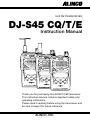
DJ-S45 CQ/T/E
Instruction Manual
Thank you for purchasing this ALINCO FM transceiver.
This instruction manual contains important safety and
operating instructions.
Please read it carefully before using the transceiver and
be sure to keep it for future reference.
ALINCO, INC.
Contents
Contents
NOTICE / Compliance Information Statement .....................3
Before Operating the Transceiver .........................................5
1.Functions and Features .......................................................6
1-1 Standard Accessories ..............................................................6
2.Accessories ..........................................................................7
2-1 Attaching and Detaching Accessories.....................................7
2-1-1 Antenna( DJ-S45 T/E only).............................................7
2-1-2 Hand Strap ......................................................................7
2-1-3 Belt Clip..........................................................................7
2-2 Setting Batteries ......................................................................8
2-3 Lithium Ion Battery Pack ........................................................8
2-4 Battery Level Indicator ...........................................................9
3.Control Functions...............................................................10
3-1 Names and Operations of the Transceiver Controls .............10
3-2 Key Operations......................................................................12
3-3 Display ..................................................................................14
4.Basic Operations................................................................15
4-1 Turning the Power ON ..........................................................15
4-2 Adjusting the Audio Volume ................................................15
4-3 Operating Modes...................................................................16
4-4 LPD (VFO) Mode .................................................................16
4-4-1 Frequency Setting .........................................................17
4-5 PMR Mode( DJ-S45 CQ only) ..............................................17
4-5-1 Frequency Number Setting...........................................17
4-6 Memory Mode.......................................................................18
4-6-1 Memory Channel Programming ...................................18
4-6-2 Selecting a Memory Channel .......................................19
4-6-3 Clearing a Memory Channel Data ................................19
4-6-4 Programmable Items to Memory Channel....................20
1
Contents
4-7 Receiving ..............................................................................20
4-7-1 Adjusting Squelch Level ..............................................20
4-7-2 Monitor Function..........................................................21
4-8 Transmitting ..........................................................................21
4-8-1 Switching of Transmission Output Level
( DJ-S45 T/E only) ........................................................22
5.Parameter Setting Mode ...................................................23
5-1 Selectable Parameters............................................................23
5-2 Selecting the Setting Mode ...................................................28
6.Advanced Operations ........................................................30
6-1 Scanning................................................................................30
6-1-1 LPD (VFO) Scan ..........................................................31
6-1-2 PMR Scan( DJ-S45 CQ only) .......................................31
6-1-3 Memory Scan................................................................32
6-1-4 Skip Channel.................................................................32
6-1-5 Tone Scan .....................................................................33
6-2 Repeater( DJ-S45 T/E only)...................................................33
6-3 Key Lock...............................................................................34
6-4 Tone Call (Tone Burst) .........................................................35
6-5 Channel Display Mode..........................................................35
7.Selective Communicating .................................................36
7-1 LPD (VFO) Tone Squelch ....................................................36
7-2 PMR Tone Squelch( DJ-S45 CQ only) .................................38
8.Cloning / Packet Operation...............................................39
8-1 Cloning..................................................................................39
8-2 Packet Operation( DJ-S45 T/E only) .....................................42
9.Maintenance and Reference .............................................43
9-1 Resetting................................................................................43
9-2 Options ..................................................................................44
10.Specifications ...................................................................45
2
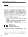
NOTICE / Compliance Information Statement
NOTICE / Compliance Information Statement
DJ-S45 T
This equipment has been tested and found to comply with the limits
for a Class B digital device, pursuant to part 15 of the FCC Rules.
These limits are designed to provide reasonable protection
against harmful interference in a residential installation.
This equipment generates, uses, and can radiate radio frequency
energy and, if not installed and used in accordance with the
instruction manual, may cause harmful interference to radio
communications. However, there is no guarantee that
interference will not occur in a particular installation. If this
equipment does cause harmful interference to radio or television
reception, which can be determined by turning the equipment off
and on, the user is encouraged to try to correct the interference
by one or more of the following measures:
• Reorient or relocate the receiving antenna.
• Increase the separation between the equipment and
receiver.
• Connect the equipment into an outlet on a circuit different
from that to which the receiver is connected.
• Consult the dealer or an experienced radio/TV technician
for help.
Tested to Comply
With FCC Standards
FOR HOME OR OFFICE USE
Information in this document is subject to change without notice
or obligation. All brand names and trademarks are the property of
their respective owners. Alinco cannot be liable for pictorial or
typographical inaccuracies. Some parts, options and/or
accessories are unavailable in certain areas. Changes or
modifications not expressly approved by the party responsible for
compliance could void the user's authority to operate the
equipment.
3
NOTICE / Compliance Information Statement
UHF FM Transceiver DJ-S45 T
This device complies with Part 15 of the FCC Rules. Operation is
subject to the following two conditions: (1) This device may not
cause harmful interference, and (2) this device must accept any
interference received, including interference that may cause
undesired operation.
Manufacturer:
ALINCO, Inc Electronics Division
Shin-Dai Bldg 9F, 2-6, 1 Chome
Dojimahama, Kita-ku, Osaka 530-0004 JAPAN
DJ-S45 E
DJ-S45 CQ
Conformity Information
In case the unit you have purchased is marked with a CE symbol,
a copy of relative conformity certificate or document can be
reviewed at http://www.alinco.com/usa.html.
Copyright © 2005 All rights reserved. No part of this document
may be reproduced, copied, translated or transcribed in any form
or by any means without the prior written permission of Alinco.
Inc., Osaka, Japan, English Edition Printed in Japan.
4
Before Operating the Transceiver
Caution
The use of transceiver in the following places is prohibited.
•Aboard aircraft •In airports •In ports •Within or near the
operating area of business wireless stations or their relay
stations.
Before using the transceiver in any of the above places, obtain
any necessary permission from the proper authorities, and be
mindful of the local laws that govern radio operation.
■ Points to Note for Using an External Power Supply
•When the power is supplied from a cigarette socket of a car, use
the cigarette lighter cable (EDH-33).
•Turn the power off when connecting or disconnecting the DC
cable.
•When using a commercial external antenna, install the antenna
ground not to become common with the ground of the external
power supply.
•This DC jack supports 3.0~6.0VDC, 2A or more external power
source. Please use an appropriate, reliable power supply, and
be mindful to the polarity (+ positive center).
•Use of non-genuine accessories will void ALINCO's factory
warranty.
5
1.Functions and Features
1. Functions and Features
■ 39 different Tone Squelch function (CTCSS)
■ TOT (Time Out Timer) function
■ Tone Call function (ALT, 1750, 2100, 1000, 1450Hz)
■ Reception Bell (Beeper) function
■ DJ-S45 T/E 3 types of Scan function (VFO, Memory, Tone)
1
4 types of Scan function (LPD (VFO),
Memory, Tone, PMR)
■ Cable Cloning
■ Rain Proof
DJ-S45 CQ
Caution
Insert the rubber covers properly and firmly into the jacks of
the external speaker, microphone, and power supply.
Connecting optional accessories to the transceiver disables
the rainproof function.
The DJ-S45 CQ/T/E is rainproof but NOT water resistant.
Therefore, NEVER rinse nor immerse it in water.
1-1 Standard Accessories
・Belt Clip (with a screw)
・Hand Strap
・Instruction Manual
The accessory status may vary depending on the versions. Please
consult with your local dealer for details.
6
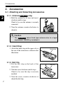
2.Accessories
2. Accessories
2-1 Attaching and Detaching Accessories
2
2-1-1 Antenna(
DJ-S45 T/E
only)
1. Hold the antenna by its base and turn it
clockwise until it stops.
Check to be sure the antenna is securely
connected.
2. Turn the antenna counter-clockwise to
detach it.
Caution
The DJ-S45 CQ takes fixed type antenna due to a legal
requirement. NEVER try to detach it.
2-1-2 Hand Strap
1. Attach the hand strap in the upper slot at
the rear of the transceiver as shown in the
illustration.
Hand strap
2-1-3 Belt Clip
1. Put the belt clip on the back of the
transceiver.
2. Turn the screw clockwise until it stops.
Check to be sure the clip is securely
installed.
3. Turn the screw counter-clockwise to
detach the belt clip.
7
Belt clip
2.Accessories
2-2 Setting Batteries
1. Open the cover latch and then open the
cover.
Cover latch
Cover
2. Set two commercially available AA
batteries in the +/- orientation marked at
the internal front side.
2
3. Close the cover and then fix it with the
cover latch.
2-3 Lithium Ion Battery Pack [EBP-60] (Option)
Please refer to the instruction manual that comes with the battery pack
for operating and charging procedures.
Caution
•Manganese batteries are not recommended as they may
decrease the transmission output level.
•Be sure to observe proper orientation of the batteries
polarity (+/-).
•Latest generation dry cells such as "Oxiride" batteries can
be used.
•Ni-MH rechargeable cells are also usable. Please carefully
read instructions of its manufacturer to properly use them.
•Regardless of the type of battery you use, please:
1.Never mix the type, brand, or different status of use.
2.Never remove protective materials around cells.
3.Clean the contacts with a dry cloth once in a while to
obtain best performance.
4.Respect all the instructions given by battery
manufacturer for safe and proper use.
8
2.Accessories
2-4 Battery Level Indicator
2
•Battery consumption level may change
depending on the surrounding temperature
or the frequency of use.
•Even if the battery icon appears to indicate
the necessity of charging the battery, it can
be used further if the usage is only for low
output transmission or reception.
Battery icon
*When the battery level
becomes low, the battery icon
appears.
Charge or replace the battery.
•The default setting of the battery pack type
is "bAt-1" which is for AA type cells.
When using Lithium Ion battery pack,
select the battery type setting to "bAt-2" in
the Setting mode (page 26, ITEM No.16) to
correctly indicate the battery level icon.
Reference : Due to the amplification circuitry used in this unit to
obtain high output with only 2 batteries, it may
happen that the unit cannot be turned on when the
battery voltage is getting low (while the low-battery
icon is on the display), but not completely
discharged yet. This is not a defect but we
recommend that:
•When the low-battery icon appears, recharge or
replace the batteries.
•When the low-battery icon appears, try not to turn
off the radio until fully use up the battery power.
When they are completely discharged the display
will turn off.
9
3.Control Functions
3. Control Functions
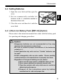
3-1 Names and Operations of the Transceiver Controls
■ Top and Front Views
①
④
3
⑤
③ ② ①
⑥
⑦
⑧
⑨
No.
Name
① Power/Volume Dial
②
MIC Connector
③
SP Connector
④
RX/TX Lamp
⑤
⑥
Speaker
F key
⑦
⑧
⑨
Display (LCD)
Keypad
Microphone
Functions
Switches power ON/OFF, and also adjusts
the audio volume.
For connection of the optional external
microphone (2k Ω) with 2.5 ø stereo plug.
For connection of the optional external
speaker(8 Ω) with 3.5 ø monophonic plug.
Illuminates green when the squelch opens
and red when transmitting.
A thin speaker is built in.
Use this key in combination with other keys to
access various functions of the transceiver.
Holding this key for 2 seconds activates the
Setting mode where various settings are
possible.
Refer to "Display" in this manual (page 14).
Refer to "Key Operations" (page 12).
Speak into microphone from a distance of
approx. 5cm at normal tone of voice.
10
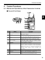
3.Control Functions
■ Side Views
⑩
⑩
⑭
⑫
3
⑪
⑬
Antenna side
No.
⑩
⑪
⑫
⑬
⑭
11
Dial side
Name
Functions
Undetachable fixed type antenna.
DJ-S45 CQ
Install the included antenna. Choose an
DJ-S45 T/E
SMA Antenna Connector antenna which has low SWR (standing Wave
Ratio) if you purchase one.
PTT (press to talk) key While this key is held down, the transceiver
transmits. When the key is released, the
transceiver returns to the receive mode.
MONI key
When this key is pressed, the squelch opens
and you can hear received signals. The
squelch also opens when the tone squelch is
set. If this key is pressed while "F" appears,
the Key Lock function is activated. Pressing
this key, while the PTT key is pressed and
held, transmits the tone call signal.
DC-IN
Terminal for connecting an external power
supply. Connect the optional cigarette lighter
cable EDH-33 for mobile operation. Use a
stable power supply with 3.0~6.0VDC, with a
capacity of 2A or more.
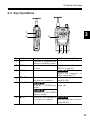
3.Control Functions
3-2 Key Operations
①
②
3
③
④ ⑤ ⑥
No.
Name
① PTT
②
MONI
③
F/SET
④
▼/T SQL
⑤
V/M / MW
⑥
▲/RPT
Independent operation
After pressing F key
Transmits or completes the
setting in the Setting mode.
Activates the monitoring Switches the key lock
ON/OFF (page 34).
function.
Accesses Various functions. DJ-S45 T/E
Adjusts the frequency in
1MHz step(page 17).
Decreases the frequency Sets the tone squelch function
(page 36~38).
and memory channels.
Programs memory channels
DJ-S45 T/E
Switches VFO/Memory (page 18).
modes.
DJ-S45 CQ
Switches LPD (VFO)/PMR/
Memory modes.
Increases the frequency DJ-S45 T/E
Sets the repeater functions
and memory channels.
(page 33~34).
12
3.Control Functions
①
②
3
③
④ ⑤ ⑥
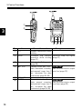
No.
Name
① PTT
13
②
MONI
③
F
④
▼/T SQL
⑤
⑥
▲/RPT
Pressed for a while
Enables transmission while
holding.
Activates the monitor
operation while holding
(page 21).
Activates the Setting mode
(page 28).
Pressed shorter than 2 sec.,
starts downward scanning,
and pressed longer than 2
sec., decreases the value
continuously (page 30~33).
During transmission
Transmits tone call signal
(page 21).
DJ-S45 T/E
Sets the transmission output
level low (page 22).
V/M / MW
Pressed shorter than 2 sec., DJ-S45 T/E
starts upward scanning, Sets the transmission output
and pressed longer than 2 level high (page 22).
sec., increases the value
continuously (page 30~33).
3.Control Functions
3-3 Display
① ②
③
⑤ ⑥
④
⑦
⑧
⑨
⑩
No.
①
②
③
④
⑤
⑥
⑦
⑧
⑨
⑩
⑪
⑫
⑬
⑭
⑮
⑯
⑰
⑱
Name
3
⑭
⑪⑫⑬ ⑮ ⑯ ⑰ ⑱
Indication
Appears when the F key is pressed.
Appears when keys are locked.
Indicates the shift (+/-) direction.
Appears when the tone encode (ENC) is set.
Appears when the tone squelch is set.
Appears when the bell function is ON.
Blinks during memory writing mode.
Indicates memory No. in the Memory mode and setting
No. in the Setting mode.
Indicates the receiving level and the transmission output.
Indicates the frequency and various setting status.
DJ-S45 T/E Appears when the repeater function is set.
DJ-S45 T/E Appears when transmission output level is high.
DJ-S45 T/E Appears when transmission output level is low.
Divides MHz and kHz of the frequency. Blinks during
scanning operation.
Appears while the Auto-Power-Off function is ON.
Appears while the Battery-Save function is ON.
Appears when the remaining battery level is low.
Appears when the squelch opens.
*Unexplained icons are not used on this transceiver.
14
4.Basic Operations
4. Basic Operations
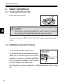
4-1 Turning the Power ON
Rotate the dial clockwise.
4
Dial
Caution
The dial also performs adjusting the audio volume. Therefore,
do not rotate it far, otherwise the audio may be too loud.
To turn the power OFF, rotate the dial counter-clockwise until it
clicks.
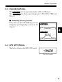
4-2 Adjusting the Audio Volume
To increase:Rotate the dial clockwise.
To decrease:Rotate the dial counter-clockwise.
When you do not hear any audio because the
squelch is closed, press and hold the MONI
key and adjust the volume to the suitable
level by listening to the white-noise.
Audio volume
decreases
Audio volume
increases
Dial
The Squelch level can be adjusted in "Adjusting Squelch Level" (page
20).
15
4.Basic Operations
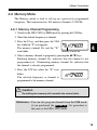
4-3 Operating Modes
The DJ-S45 T/E has two operating modes; VFO and Memory.
The DJ-S45 CQ has three operating modes; LPD (VFO), PMR and
Memory.
■ Switching among modes
Every time you press the V/M key, you can
change the operating mode as shown in the
diagram.
DJ-S45 T/E
VFO
Memory
4
DJ-S45 CQ
LPD (VFO)
PMR
Memory
4-4 LPD (VFO) Mode
The factory setting is the LPD (VFO) mode.
LPD (VFO) mode
16
4.Basic Operations
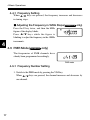
4-4-1 Frequency Setting
When ▲/▼ keys are pressed, the frequency increases and decreases
in tuning steps.
4
■ Adjusting the Frequency in 1MHz Steps( DJ-S45 T/E only)
Press the F key twice, and then the MHz
figure of the display blinks.
Press ▲/▼ keys while the figure is
blinking to adjust the frequency in the 1MHz
increments.
4-5 PMR Mode(
DJ-S45 CQ
only)
The frequencies of PMR channels have
already been programmed accordingly.
PMR mode
4-5-1 Frequency Number Setting
1. Switch to the PMR mode by pressing the V/M key.
When ▲/▼ keys are pressed, the channel increases and decreases by
one channel.
17
4.Basic Operations
4-6 Memory Mode
The Memory mode is used to call up on a previously programmed
frequency. This transceiver has 100 memory channels (0~99CH).
4-6-1 Memory Channel Programming
1. Switch to the LPD (VFO) or PMR mode by pressing the V/M key.
2. Select the desired frequency or channel.
3. Press the F key, and then press the V/M
key while the "F" icon appears.
The memory channel No. and the "W"
icon blinks.
4
Memory Channel No.
4. Select a memory channel to program by pressing the ▲/▼ keys.
Blinking memory channel No. indicates that the channel is not
programmed yet. Illuminating memory channel No. indicates that
the channel is already programmed.
5. Press the V/W key while the "W" icon
blinks.
The selected frequency or channel is
programmed to the memory channel.
Caution
Re-editing the memory will overwrite the current data.
Reference : You can also program channels from the PMR mode
if you purchased the DJ-S45 CQ . Its procedure is
the same as the LPD (VFO) mode.
18
4.Basic Operations
4-6-2 Selecting a Memory Channel
4
1. Switch to the Memory mode by pressing
the V/M key. The memory channel No.
appears on the display.
The Memory mode is not activated if
there is no preprogrammed data in the
Memory channels.
By pressing ▲/▼ keys, memory No.
increases and decreases by programmed
channels in numerical order.
Memory mode
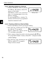
4-6-3 Clearing a Memory Channel Data
1. Switch to the Memory mode by pressing the V/M key.
2. Press the F key, and then press the V/M
key while the "F" icon appears.
Memory channel No. appears and the
"W" icon blinks on the display.
3. Select a memory channel you wish to clear by pressing the ▲/▼ keys.
On a programmed channel, "memory channel No." is displayed steadily
(without blinking).
4. Press the F key again, and then press the
MW key while the "F" icon appears.
The pre-set data is cleared.
19
4.Basic Operations
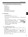
4-6-4 Programmable Items to Memory Channel
The following data can be stored in each memory channel.
•Frequency
•Offset Frequency
•Shift Direction
•Tone Frequency
•Skip CH Setting
•Tone Encoder / Decoder Settings
•Busy Channel Lock Out (BCLO)
4
4-7 Receiving
1. Turn the power ON.
2. Rotate the dial to adjust the audio volume.
3. Eliminate the noise by setting the squelch. Refer to "Adjusting Squelch
Level" below.
4. Select the desired frequency or channel.
When a signal is received on the selected
frequency, "BUSY" appears on the
display and the received signal is heard.
The S meter indicates the signal strength
of receiving signal.
S meter
4-7-1 Adjusting Squelch Level
"Squelch" is a function for eliminating noise when no signals are
being received.
Press ▲/▼ keys while the MONI key are
held down. By repeating this operation, the
display switches from "SqL-00"to "SqL-20".
The higher the level is set, the squelch
opens with the stronger signal.
20
4.Basic Operations
4-7-2 Monitor Function
•While the MONI key is pressed, the squelch opens and noise is heard
from the speaker regardless of the squelch setting. "BUSY" appears
on the display.
•Weak signals under the squelch threshold level can be heard, using
this function.
•Monitoring the selected frequency can be performed even if the tone
squelch is set.
4
4-8 Transmitting
1. Select the desired frequency or channel.
2. Press and hold the PTT key, speak into
microphone with normal loudness and
tone. The S meter indicates that the unit
is in the transmitting mode. Speak into
the microphone from a distance of
approximately 5cm.
3. Release the PTT key to stop transmitting and to return to the receiving
mode.
Reference : A tone call signal is transmitted by pressing and
holding the PTT key and pressing the MONI key
(There are 5 tone call signals that are selectable in
the Setting mode).
If the PTT key is pressed when the frequency is
outside of the transmitting range, "OFF" appears on
the display. You cannot transmit in this status.
21
4.Basic Operations
4-8-1 Switching of Transmission Output Level(
DJ-S45 T/E
only)
Transmission power can be changed to HI/LO by pressing the ▲/▼
keys while transmitting.
"LO" appears on the display when the transmitting power is low, and
"HI" appears when the transmitting power is high. Initial setting is "HI".
Low
High
4
22
5.Parameter Setting Mode
5. Parameter Setting Mode
In the Setting mode, you can set various functions of the DJ-S45 CQ/T/E .
5-1 Selectable Parameters
Please refer to "5-2 Selecting the Setting Mode" (page 28) for how to
enter to the Parameter Setting mode and "9-1 Resetting" (page 43) for
the initial factory (default) settings.
The ITEM No. increases when the F key is pressed, and it decreases
when MONI key is pressed.
5
Reference : When activating the Setting mode from the Memory
mode of the DJ-S45 CQ , the item No. differs depending
on the mode which you programmed the channel.
•The ITEM No. of the LPD (VFO) mode indicates if
the channel is programmed in the LPD (VFO) mode.
•The ITEM No. of the PMR mode indicates if the
channel is programmed in the PMR mode.
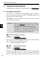
■ StP-1250 Tuning step setting
ITEM No.
01 DJ-S45 T/E
01 DJ-S45 CQ LPD (VFO) mode
The tuning steps can be changed (5/6.25/10/12.5/15/20/25/30/50).
This can be set only in the LPD (VFO) mode.
("---.---" appears in the Memory mode.)
■ SHIFt
ITEM No.
Shift direction setting
02 DJ-S45 T/E
02 DJ-S45 CQ LPD (VFO) mode
Shift the transmitting frequency in relation to the receiving frequency
as per the offset direction. Only + and - icons appear to indicate the
direction. For simplex operation, select OFF status (without +/- icons).
23
5.Parameter Setting Mode
■ 00.600
Offset frequency setting
ITEM No.
03 DJ-S45 T/E
03 DJ-S45 CQ LPD (VFO) mode
This function sets the width of the frequency shift (0-99.995MHz).
■ bEP-on
Beeper ON/OFF
ITEM No.
04 DJ-S45 T/E
04 DJ-S45 CQ LPD (VFO) mode
01 DJ-S45 CQ PMR mode
Select ON to enable a beep that sounds after certain keys are touched
and/or setting is done.
■ ALt
Call tone setting
ITEM No.
05 DJ-S45 T/E
05 DJ-S45 CQ LPD (VFO) mode
02 DJ-S45 CQ PMR mode
The call tone sound is selected (ALT/1000/1450/1750/2100Hz).
Set the tone burst tone with this parameter.
■ to-oFF
5
TOT setting (seconds)
ITEM No.
06 DJ-S45 T/E
06 DJ-S45 CQ LPD (VFO) mode
03 DJ-S45 CQ PMR mode
Limit the time of a signal transmission (OFF/30/60/90/---/450sec).
When the TOT time is elapsed, the transceiver automatically shifts to
the receive status.
■ AP-oFF
APO setting (minutes)
ITEM No.
07 DJ-S45 T/E
07 DJ-S45 CQ LPD (VFO) mode
04 DJ-S45 CQ PMR mode
This function prevents wasting the battery power when you forget to
turn the transceiver off (OFF/30/60/90/120min).
This function automatically turns off the power if there is no operation
for the specified period of time.
24
5.Parameter Setting Mode
■ bS-on
Battery saving ON/OFF
ITEM No.
08 DJ-S45 T/E
08 DJ-S45 CQ LPD (VFO) mode
05 DJ-S45 CQ PMR mode
Select ON to save the battery consumption during the stand-by status.
■ bEL-oF
Bell ON/OFF
ITEM No.
09 DJ-S45 T/E
09 DJ-S45 CQ LPD (VFO) mode
06 DJ-S45 CQ PMR mode
The bell function can inform you a signal is being received by a tone
sound and LCD indication (Bell icon) like a pager.
■ Stb-on
5
Stand-by-beep ON/OFF
ITEM No.
10 DJ-S45 T/E
10 DJ-S45 CQ LPD (VFO) mode
07 DJ-S45 CQ PMR mode
When you release the PTT key, a beep sound is transmitted informing
your partner(s) your transmission has ended.
■ bCL-oF
ITEM No.
BCLO ON/OFF
11 DJ-S45 T/E
11 DJ-S45 CQ LPD (VFO) mode
08 DJ-S45 CQ PMR mode
The BCLO stands for "Busy Channel Lock Out" and prohibits
transmission when the channel is busy.
When BCLO is on, transmitting is available only in the following
cases:
•When no signals are received ("BUSY" disappears)
•When a tone matches in the TSQ setting
25
5.Parameter Setting Mode
■ SCAn-t
Scan (timed/busy channel) switching
ITEM No.
12 DJ-S45 T/E
12 DJ-S45 CQ LPD (VFO) mode
09 DJ-S45 CQ PMR mode
Choose between timed scan (SCAn-t) and busy channel scan (SCAn-b).
Refer to "6-1 Scanning"(page 30) for details.
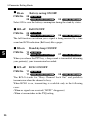
■ m**-oF
Scan skip setting
ITEM No.
13 DJ-S45 T/E
13 DJ-S45 CQ LPD (VFO) mode
10 DJ-S45 CQ PMR mode
Memory channel numbers that you want to skip while in Memory
Scan operation. You cannot designate channels to skip if no memory
channels are programmed. This can be set only in the Memory mode.
("---.---" appears in the LPD (VFO) mode and the PMR mode.)
■ EPo-oF
5
External terminal control ON/OFF
ITEM No.
14 DJ-S45 T/E
14 DJ-S45 CQ LPD (VFO) mode
11 DJ-S45 CQ PMR mode
Parameter ON outputs 3.0V from the external MIC terminal when the
squelch is on (5mA max).
■ Lmp-5
Lamp ON/OFF
ITEM No.
15 DJ-S45 T/E
15 DJ-S45 CQ LPD (VFO) mode
12 DJ-S45 CQ PMR mode
Select OFF to cancel illumination, ON to always illuminate, and 5 to
illuminate the display for 5 seconds at each key operation (except PTT).
■ bAt-1
Battery type switching
ITEM No.
16 DJ-S45 T/E
16 DJ-S45 CQ LPD (VFO) mode
13 DJ-S45 CQ PMR mode
Choose the battery type between AA cells (bAt-1) and optional
Lithium Ion battery (bAt-2) to properly indicate the low-battery icon.
Refer to "2-4 Battery Level Indicator"(page 9) for details of battery type.
26
5.Parameter Setting Mode
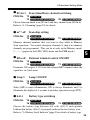
■ SHIFt
ITEM No.
■ 05.000
ITEM No.
■ tonE
ITEM No.
■ 88.5
ITEM No.
5
Repeater shift direction setting
17 DJ-S45 T/E
Repeater offset frequency setting
18 DJ-S45 T/E
Repeater tone encoding ON/OF
19 DJ-S45 T/E
Repeater tone frequency setting
20 DJ-S45 T/E
Above items No.17 to 20 are related to "Quick-Repeater-Access"
ONLY. Refer to page X for operation. ITEM No. 17 and 18 set the
same parameters as explained in ITEM No.2 and 3, ITEM No.19 to
determine encoding status, and ITEM No. 20 to select the encoding
tone.
The Mode Setting Chart is on the next page to cut off for your
convinience.
27
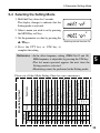
ITEM NO.
DJ-S45 DJ-S45 CQ
T/E LPD PMR
01 01
02 02
03 03
04 04 01
05 05 02
06 06 03
07 07 04
08 08 05
09 09 06
10 10 07
11 11 08
12 12 09
13 13 10
14 14 11
15 15 12
16 16 13
17
18
19
20
Functions
Tuning step setting
Shift direction setting
Offset Frequency setting
Beeper ON/OFF
Call tone setting
TOT setting (seconds)
APO setting (minutes)
Battery saving ON/OFF
Bell ON/OFF
Stand-by-beep ON/OFF
BCLO ON/OFF
Scan (timed/busy channel)switching
Scan skip setting
External terminal controlling ON/OFF
Lamp 5sec/ON/OFF
Battery type (AA/Li-ion)switching
Quick- Shift direction setting
Repeater- Offset Frequency setting
Access Tone ON/OFF
only
Tone Frequency setting
Display
StP-1250
SHIFt
00.600
bEP-on
ALt
to-oFF
AP-oFF
bS-on
bEL-oF
Stb-on
bCL-oF
SCAn-t
m**-oF
EPo-oF
Lmp-5
bAt-1
SHIFt
05.000
tonE
88.5
Mode Setting Chart
5.Parameter Setting Mode
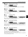
5-2 Selecting the Setting Mode
1. Hold the F key down for 2 seconds.
The display changes to indicate that the
Setting mode is activated.
2. Select a menu you wish to set by pressing
the MONI key or F key.
3. Set the parameter or value by pressing the
▲/▼keys.
Switching the bell function On
4. Press the PTT key or V/M key to
complete the setting.
Reference : •In the offset frequency setting (ITEM No.03 and 18),
MHz frequency is adjustable by pressing the V/M key.
•The last menu operated appears the next time the
Setting mode is activated.
•Monitoring cannot be performed in the Setting mode.
5
Please cut off this Mode Setting Chart for your convenience.
28
5.Parameter Setting Mode
5
29
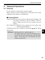
6.Advanced Operations
6. Advanced Operations
6-1 Scanning
Use this function to automatically search for signals.
When a signal is received, scanning pauses, and resumes after a while
depending on the settings of scanning mode.
■ Scanning Modes
Timed Scan:While the scan is pausing, when the signal disappears, the
scan resumes and moves to the next channel. Even if a
signal is being received, the scan resumes after five
seconds.
Busy Channel Scan:While the scan is pausing, the scan resumes, only
when the signal disappears.
Scanning direction can be changed by pressing the ▲/▼ keys during
the operation.
Reference : Scanning in the tone-squelch operation:
The squelch opens only when the decoding tone of
your unit matches the encoding tone of the incoming
signal. In case the tones are different, the scan
resumes automatically.
6
30
6.Advanced Operations
6-1-1 LPD (VFO) Scan
Scans the entire band in the LPD (VFO) mode.
1. Switch to the LPD (VFO) mode by
pressing the V/M key.
2. Press and hold the ▲/▼ keys for 1 to 2
seconds to start scanning.
The decimal point blinks during the scan.
Scanning direction goes upward by
pressing the ▲ key, and downward by
pressing the ▼ key.
6
3. To stop scanning, press the PTT key, the
F key or the V/M key.
While MONI key is being pressed,
scanning stops temporarily and monitor
function is activated. When the key is
released, scanning restarts.
6-1-2 PMR Scan (
DJ-S45 CQ
only)
Scans all channels in the PMR mode.
1. Switch to the PMR mode by pressing the
V/M key.
2. The procedures are the same as the LPD
(VFO) scan. Refer to the procedures of
step2 and 3 above.
31
PMR mode
6.Advanced Operations
6-1-3 Memory Scan
Scans only the programmed memory channels.
1. Switch to the Memory mode by pressing
the V/M key.
2. Press and hold the ▲/▼ keys for 1 to 2
seconds to start scanning.
The decimal point blinks during the scan.
The operation is the same as the LPD
(VFO) scan.
3. To stop scanning, press the PTT key, the
F key or the V/M key.
While MONI key is being pressed,
scanning stops temporarily and monitor
function is activated. When the key is
released, scanning restarts.
6-1-4 Skip Channel
6
Memory channels where a memory skip is
programmed are out of target for scanning in
the memory scanning.
In the memory channel where a memory
skip is programmed, the decimal point
disappears on the display. Refer to "Scan
skip setting"(page 26) for setting procedure.
32
6.Advanced Operations
6-1-5 Tone Scan
This function helps you to find the tone frequency in case CTCSS
system is used.
1. Press and hold the ▲/▼ keys for 1 to 2
seconds in the tone squelch setting mode
(page 36~38).
LPD (VFO) mode
Scanning starts and the decimal point
blinks.
39 kinds of tone frequencies are scanned
in order.
When the tone frequency matches,
PMR mode
scanning stops and you can hear the
received signal.
Scanning will not resume until the ▲/▼
keys are pressed again.
6
2. To cancel the tone scan, press the PTT
key, the F key or the V/M key.
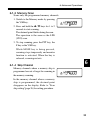
6-2 Repeater (
DJ-S45 T/E
only)
Repeaters (Automatic relay stations) are located on top of buildings or
mountaintops to allow the communication with stations far away.
33
6.Advanced Operations
■ Quick-Repeater-Access Operation
1. Press the V/M key to activate the LPD
(VFO) mode.
2. Press the F key, then the ▲ key while the
"F" icon appears. The "XX" icon appears
on the display and the repeater function is
set. The shift frequency, direction and
tone set in the Setting mode (page 27,
ITEM No.17 to 20) are applied
automatically.
3. To cancel this function, repeat the
procedure step 2, and the "XX" icon will
disappear.
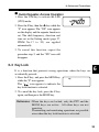
6-3 Key Lock
It is a function that prevents wrong operations when the keys are
accidentally pressed.
1. Press the F key, and press the MONI key
while the "F" icon appears.
The " " icon appears to indicate the
key lock function is activated.
6
2. To cancel the key lock, press the F key
again, and then press the MONI key.
Reference : When the keys are locked, only the PTT and the
MONI keys are active. All other keys are not
operative.
Transmitting and monitoring operations are possible
even when the key lock function is activated.
34
6.Advanced Operations
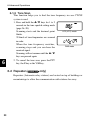
6-4 Tone Call (Tone Burst)
Use this function to call a partner by adding an audible tone to the
transmitting signal.
The tone signal is output while the MONI key is pressed down while
the PTT key is pressed and held. The call tone sound can be selected
in the Setting mode (page 24, ITEM No.05).
Use this function to access tone burst system repeaters by selecting
proper tone.
Caution
A tone call signal cannot be output with a tone ENC signal.
During call tone output, the ENC signal cannot be transmitted.
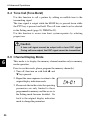
6-5 Channel Display Mode
6
This mode is to display the memory channel number only in memory
mode operation.
Prior to use this mode, please program the memory channel(s).
1. Turn off, then turn on with both ▲ and
▼ keys pressed.
2. Repeat the same sequence to return to the
original display indication mode.
3. Please note that in this status the operating
parameters are only limited to those
programmed in memory and the access to
the Setting mode becomes disabled. Go
back to the original display indication
mode to change the parameters.
35
7.Selective Communicating
7. Selective Communicating
When communicating with a specific station, tone squelch (CTCSS)
function can be used. Tone squelch is a function that enables to
receive the signal only when its encoding tone matches to your tone
decode setting.
There are 39 different selectable tone frequencies/numbers.
No.
01
02
03
04
05
06
07
08
09
10
Frequency
67.0
69.3
71.9
74.4
77.0
79.7
82.5
85.4
88.5
91.5
No.
11
12
13
14
15
16
17
18
19
20
Frequency
94.8
97.4
100.0
103.5
107.2
110.9
114.8
118.8
123.0
127.3
No.
21
22
23
24
25
26
27
28
29
30
Frequency
131.8
136.5
141.3
146.2
151.4
156.7
162.2
167.9
173.8
179.9
No.
31
32
33
34
35
36
37
38
39
Frequency
186.2
192.8
203.5
21.07
218.1
225.7
233.6
241.8
250.3
7-1 LPD (VFO) Tone Squelch
1. Press the V/M key to activate the LPD
(VFO) mode.
2. Press the F key, then the T SQL key
while "F" icon appears.
By repeating this process, icon rotates as
shown.
T
TSQ
(OFF)*
7
*Nothing appears on the display.
3. Change the tone frequency with ▲/▼
keys.
Select the tone frequency to use from the
list above. Please note that T and TSQ
tones (ENC/DEC tones) can be set
separately and make sure both tones are
set correctly.
36
7.Selective Communicating
4. Press the PTT key or the V/M key to
complete the setting and return to the
LPD (VFO) mode.
When "T" is displayed, the tone ENC is set. Only the tone
transmitting functions operates (encode).
When "T SQ" is displayed, the tone squelch is set. Both the tone
transmitting functions and the tone squelch operate (decode).
The CTCSS operation is deactivated when none of icons appear.
Reference : Monitoring can be performed by pressing the MONI
key even during setting operation.
Caution
•The higher TSQ (decode) frequency setting may risk instable
TSQ operation which the squelch may open by receiving a
certain tone of voice signal close to the TSQ frequency.
•It is recommended to adjust normal squelch level anyway
even TSQ is activated (page 20).
7
37
7.Selective Communicating
7-2 PMR Tone Squelch (
DJ-S45 CQ
only)
1. Press the V/M key to activate the PMR
mode.
2. Press the F key, then the T SQL key
while "F" icon appears. The tone number
blinks. The default setting is "09".
3. Change the tone number with ▲/▼
keys.
Select the tone number to use from the list
above.
4. Press the PTT key or the V/M key to
complete the setting and return to the
PMR mode.
Select OFF (oF) to disable the tone squelch operation. In PMR tone
squelch operation, the encoding and decoding tones are always the
same and cannot be set separately.
7
38
8.Cloning / Packet Operation
8. Cloning / Packet Operation
8-1 Cloning
When using the cloning function, all setting information (including
memory data) of one transceiver (master unit) can be transferred and
copied to another transceiver (slave unit) by connecting them with a
cable.
■ Connecting the Transceivers
Connect the external speaker jacks on both the master and slave
transceivers with commercially available φ 3.5 stereo mini plug
cable. If you prefer to make one, please refer the chart below.
After connecting them, turn the both units' power ON.
Caution
Connect the cable only when the transceiver power is OFF.
Master
To SP jack on the transceiver
Slave
To SP jack on the transceiver
*
8
¿3.5 stereo mini plug cable
*It is not a problem if there is a connection between the top of the plug.
39
8.Cloning / Packet Operation
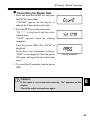
■ Transmitting the Master Data
1. Press and hold the MONI key and press
the PTT key three times.
"CLONE" appears on the display to
indicate the Clone mode is activated.
2. Press the PTT key on the master unit.
"Sd ***" is displayed and the datatransfer starts.
"PASS" appears when the cloning
completes.
Turn the power OFF after "PASS" is
displayed.
If the data is not transmitted correctly,
"PASS" is not displayed. Turn the power
ON again, and repeat the procedure from
step 1.
Cloning completed
3. To cancel the Clone mode, turn the power
OFF.
Caution
If the cable is not connected correctly, "Err" appears on the
display.
Check the cable connections again.
8
40
8.Cloning / Packet Operation
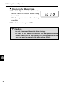
■ Receiving the Master Data
1. "Ld ***" appears on the slave unit's
display while the master data is being
transmitted.
"End" appears when the cloning
completes.
2. Turn the transceiver power OFF.
Caution
•Do not disconnect the cable while cloning.
•All data in the slave transceiver will be updated to the
master transceiver's data during the cloning operation. Be
sure you want to overwrite the data before cloning.
8
41
8.Cloning / Packet Operation
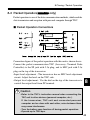
8-2 Packet Operation(
DJ-S45 T/E
only)
Packet operation is one of the data communication methods, which enables
data transmission and reception with personal computer through TNC.
■ Packet Operation Connections
3.5¿ PLUG
SP
SP
T
GND
GND
2.5¿ PLUG
10µF
MIC
MIC
3.0V
N
C
10k½
PTT
GND
GND
(Low)
3.0V
Power is supplied from internal 3V line through a 100½ resistor.
Connection figure of the packet operation with this unit is shown above.
Connect the packet communication TNC (Accessory: Terminal Node
Controller) to the SP jack with 3.5ø plug, and to MIC jack with 2.5ø
plug on the top of the transceiver.
•Input level adjustment : The transceiver has no MIC level adjustment
circuit. Adjust the level on the TNC side.
•Output level adjustment : Use the dial on the top of the transceiver to
control the output level from SP terminal.
8
Caution
•Refer to the TNC's instruction manual when connecting the
TNC unit to other devices (personal computer, etc.).
If the transceiver, TNC unit and connected personal
computer are too close with each other, noise between them
may cause interference.
•Turn the battery save function off during packet operation.
•Operate up to 1200 bps.
42
9.Maintenance and Reference
9. Maintenance and Reference
9-1 Resetting
When you reset the transceiver, all settings are returned to the initial
factory (default) settings.
1. Turn the power ON while the F key and V/M key are held down.
2. While all the display indications appear, release the keys.
Initial Factory Settings
9
43
DJ-S45
DJ-S45 CQ
T
E
LPD (VFO) mode PMR mode
Frequency
445.000MHz 433.000MHz 434.000MHz
1ch
Memory Channel(0~99)
Unset
Unset
Unset
Unset
Tone Squlech Setting
•••
•••
•••
•••
Transmit Tone Frequcney
•••
88.5Hz
88.5Hz
88.5Hz
Receive Tone Frequcney
•••
88.5Hz
88.5Hz
88.5Hz
Transmit Power
LOW
LOW
Key Lock
OFF
OFF
OFF
OFF
Squelch Level
07
07
07
07
Tuning Step
5.0kHz
12.5kHz
12.5kHz
Shift Direction
•••
•••
•••
Shift Frquency
5.0MHz
5.0MHz
0.6MHz
Beeper
ON
ON
ON
ON
Tone Call
1750Hz
ALT
ALT
ALT
TOT
OFF
OFF
OFF
OFF
APO
OFF
OFF
OFF
OFF
Battery Saving
ON
ON
ON
ON
Bell
OFF
OFF
OFF
OFF
Stand-by-beep
ON
OFF
OFF
ON
BCLO
OFF
OFF
OFF
OFF
Scan Mode
Timed
Timed
Timed
Timed
Scan Skip
OFF
OFF
OFF
OFF
External Terminal Controlling
OFF
OFF
OFF
OFF
Lamp Function
ON (5sec.) ON (5sec.) ON (5sec.) ON (5sec.)
Battery Type
1(AA)
1(AA)
1(AA)
1(AA)
Repeater Shift Direction
- (Minus)
- (Minus)
Repeater Shift Frequency
5.0MHz
5.0MHz
Repeater Tone Setting
ON
OFF
Repeater Tone Frequency
88.5Hz
88.5Hz
9.Maintenance and Reference
9-2 Options
EBP-60
EDC-138A
EDC-138E/uk
EDC-138R
EDH-33
EME-12A
EME-13A
EME-15A
EME-21A
EME-23A
EME-26
EME-6
EMS-59
ESC-40
Lithium Ion Battery Pack
Quick Battery Charger 120Vac
Quick Battery Charger 240Vac
Additional Basket (to convert EDC-138 a
multiple charger)
Cigar DC/DC Converter
Head Set with VOX (Speaker Type)
Head Set with VOX (Earphone Type)
Tie Pin Microphone with VOX
Earphone Microphone (Heavy-Duty)
Earphone Microphone
Curl-Cable Earphone
Earphone
Speaker Microphone
Soft Case
* DJ-S45 CQ/E : Note for RoHS compliance
Some of the accessories listed above are not RoHS compliant at the
moment this manual has been edited. Please refer an updated
brochure or ask your dealer for eventual replacements at the moment
of the purchase after July 2006.
9
44
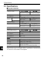
10.Specifications
10. Specifications
■ DJ-S45 CQS/CQL
General
Frequency Range
Modulation
Ant. Impedance
Supply Voltage
Current
Transmit
(DC6.0V)
Receive
Frequency Stability
Dimension
Weight
LPD (VFO) mode
PMR mode
TX;433.06000-434.78000MHz TX;446.00625-446.09375MHz
RX;433.06000-434.78000MHz RX;446.00625-446.09375MHz
F3
50 Ω
3.0-6.0VDC(DC-JACK), 2xAA Batteries, Li-ion pack
LPD (VFO) mode
PMR mode
Approx.0.45A
Approx.0.20A
Approx. 60mA
+5~-5ppm
57(W) x98 (H) x27.9 (D) mm (Projections exclusive)
DJ-S45CQS
DJ-S45CQL
Approx. 170g
Approx. 164g
(2xAA Batteries inclusive) (2xAA Batteries inclusive)
Transmitter
Power Output (DC6.0V)
Modulation
Max. Deviation
Spurious Emission
Mic. Impedance
LPD (VFO) mode
Approx. 10mW
Variable Reactance
+/-2.5kHz
250nW or less
Approx. 2k Ω
PMR mode
Approx. 500mW
Receiver
System
Intermediate Freq.
Sensitivity
Selectivity
AF Output
Spurious response
10
45
FM: Double-conversion super heterodyne
FM: 1st 21.7MHz, 2nd 450kHz
-15dBu or less (12dB SINAD)
FM: -6dB; 6kHz or over, -60dB; 14kHz or less
180mW or over (MAX)
150mW or over (10% Distortion Factor 8 Ω)
2nW or less
•Specifications may be changed without a preliminary announcement
in connection with technical development.
10.Specifications
■ DJ-S45 T/E
General
Frequency Range
Modulation
Ant. Impedance
Supply Voltage
Current
Transmit
(DC6.0V)
Receive
Frequency Stability
Dimension
Weight
DJ-S45 T
DJ-S45 E
TX: 420.000-449.995MHz
TX: 430.000-439.995MHz
RX: 420.000-473.995MHz
RX: 430.000-439.995MHz
F3
50 Ω
3.0-6.0VDC(DC-JACK), 2xAA Batteries, Li-ion pack
Hi-Power
Lo-Power
Approx.0.45A
Approx.1.00A
Approx. 60mA
+5~-5ppm
57(W) x98 (H) x27.9 (D) mm (Projections exclusive)
Approx. 162g
(2xAA Batteries and SMA Antenna inclusive)
Transmitter
Power Output (DC6.0V)
Modulation
Max. Deviation
Spurious Emission
Mic. Impedance
Hi-Power
Approx. 2W
Variable Reactance
+/-5.0kHz
-60dB or less
Approx. 2k Ω
Lo-Power
Approx.0.5W
Receiver
System
Intermediate Freq.
Sensitivity
Selectivity
AF Output
Spurious response
FM: Double-conversion super heterodyne
FM: 1st 21.7MHz, 2nd 450kHz
-15dBu or less (12dB SINAD)
FM: -6dB; 12kHz or over, -60dB; 35kHz or less
180mW or over (MAX)
150mW or over (10% Distortion Factor 8 Ω)
60dB or over
•Specifications may be changed without a preliminary announcement
in connection with technical development.
10
46
ALINCO, INC.
Head Office:Shin-Dai building 9th Floor
2-6, 1-Chome, Dojimahama, Kita-ku, Osaka 530-0004, JAPAN
Phone:+81-6-4797-2136 Fax: +81-6-4797-2157
E-mail:[email protected]
Printed in Japan
Copyright Alinco, Inc. 2005 PS0504