1
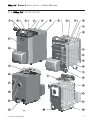
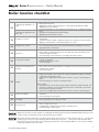
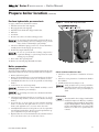
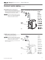
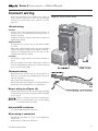
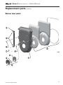
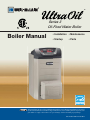
®
Series 3
Oil-Fired Water Boiler
Boiler Manual
• Installation • Maintenance
• Startup
• Parts
This manual must only be used by a qualified heating installer/service technician. Read all instructions, including this manual and all other information shipped with the boiler, before installing. Perform steps in the order
given. Failure to comply could result in severe personal injury, death or substantial property damage.
Part number 550-142-182/1014
®
Series 3
— Boiler Manual
®
THE
1.
WATER BOILER
WATER BOILER
– HOW IT WORKS . . .
Weil-McLain logo plate (standard) or
Remote Display Module (optional)
The Remote Display Module (RDM) is used when the optional
AFM (item 28) is installed. The display shows boiler and system
status and is used to adjust operating parameters.
2.
ON/OFF switch
3.
Control Pod cover fastener
4.
Pressure/Temperature gauge
19. Sensor wells
Boiler limit temperature sensor and P/T gauge capillary and temperature sensor are installed in the top of the rear section.
20. Outlet tapping
The boiler outlet water tapping is located in the top of the rear
section.
21. Return tapping
Displays boiler water pressure and outlet water temperature.
5.
Jacket top rear panel
6.
Control Pod cover
22. Insulation blanket
The
Control Pod cover is hinged to allow easy access to
the limit temperature sensor, boiler wiring and optional Advanced
Features Module (AFM).
23. Leveling legs
Jacket side panels
25. Flue connection
®
7.
The boiler return tapping is located in the bottom of the rear
section.
®
jacket side panels are interchangeable.
8.
Jacket rear panel, with insulation
9.
Terminal strip
Electrical connections, both line and low voltage, connect to the
terminal strip.
24. Boiler drain valve
®
boilers can be chimney or direct vented from the rear
flue opening.
26. Knockouts in jacket rear for electrical conduits
All electrical connections enter in conduits connected to these
knockouts.
10. Front section
27. Boiler relief valve
11. Intermediate sections
28. AFM (Advanced Features Module) — Optional
®
12. Back section
13. Burner wire harness
Line voltage wiring to burner, terminated in a Molex connector
in the jacket cross tie (item 19). An additional harness connects
from the cross tie connector to the burner.
14. Burner door hinge bracket
The hinge bracket can be installed on either side to allow for right
or left-hand swing.
15. Swing-away burner door
®
The
burner door is hinged to provide easy access to the
boiler heat exchanger for inspection and cleaning.
16. Rotating observation port
®
The
observation port is designed to prevent soot from
depositing on the sight glass. During normal operation the sight
glass is located at the 12:00 position. To view the burner flame,
loosen the center mounting bolt and rotate so the sight glass is
in the 6:00 position.
The
boiler can be equipped with the Advanced Features
Module (AFM). The AFM is a system control that provides boiler
outdoor reset, a boiler setpoint temperature, domestic hot water
pump operation, and outdoor reset through the use of a mixing
valve or a variable speed injection pump. It also controls staging
and rotation of two boilers.
When equipped with an AFM, the boiler requires a 20-amp
service.
29. Temperature Limit/LWCO Control with Thermal
TargetingTM The Ultra Oil boiler is equipped with a Hydrolevel 3250 HydroStat®, LWCO and temperature limit control
with energy saving technology. The 3250 senses the presences
of water, water temperature and monitors calls for heat and
activates the boiler pump and circulator. The control logic will
delay pump or burner operation and adjust them for the target
water temperature to optimize efficiency.
30. Burner, with cover
17. Overfire pressure tapping
1/8” npt, with plug.
31. Jacket front panel
18. Jacket cross tie
2
Part number 550-142-182/1014
®
Series 3
THE
WATER BOILER
— Boiler Manual
®
Part number 550-142-182/1014
WATER BOILER
3
®
Series 3
WATER BOILER
— Boiler Manual
Contents
®
THE
WATER BOILER — HOW IT WORKS............................ 2–3
Please read before proceeding ............................................. 5
Owners Responsibilities ........................................................ 6
Boiler location checklist ....................................................... 7
Prepare boiler location .......................................................... 8
Connect breeching .............................................................. 12
Connect water piping .......................................................... 14
Connect wiring (Note 1) ........................................................... 18
Connect oil piping ............................................................... 22
Startup procedure ............................................................... 23
Check-out procedure ........................................................... 24
Annual service and start-up ................................................ 25
Department of Energy Compliance ..................................... 28
Removing/replacing boiler jacket ........................................30
Replacement parts ............................................................. 32
Dimensions ......................................................................... 38
Ratings ................................................................................ 39
Note 1:
See burner manual for wiring and additional startup and operating information.
Also see AFM manual if used.
The terms below are used throughout this manual to bring attention to the presence of hazards of various risk levels
or to important information concerning the life of the product.
Indicates presence of hazards that will cause
severe personal injury, death or substantial
property damage.
Indicates presence of hazards that will or
can cause minor personal injury or property
damage.
Indicates presence of hazards that can cause
severe personal injury, death or substantial
property damage.
Indicates special instructions on installation, operation or maintenance
that are important but not related
to personal injury or property damage.
When calling or writing about the boiler—
Please have the boiler model number from
the boiler rating label and the CP number
from the boiler jacket. You may list the CP
number in the space provided on the Installation Certificate found on page 24.
Consider piping and installation when determining boiler location.
Any claims for damage or shortage in shipment must be filed immediately against the
transportation company by the consignee.
4
Commonwealth of Massachusetts
When the boiler is installed within the Commonwealth of Massachusetts:
• This product must be installed by a licensed
plumber.
• If antifreeze is used, a reduced pressure backflow preventer device shall be used.
Part number 550-142-182/1014
®
Series 3
WATER BOILER
— Boiler Manual
Please read before proceeding
Follow the guidelines below to prevent severe personal injury, death or substantial property damage.
Fuel
Do not start burner if:
•
•
•
Do not use crankcase drainings or any oil containing
gasoline. See burner manual for proper fuel oil.
Never burn garbage or paper in the boiler. Never leave
combustible material around boiler.
Do not attempt to start burner when excess oil has accumulated in combustion chamber, when unit is full of
vapor, or when combustion chamber is very hot.
Do not start burner unless breeching and burner mounting door are secured in place.
•
Do not tamper with burner/controls
•
Always follow specific instructions when starting up
boiler or performing routine maintenance or service.
Follow the guidelines below to prevent possible severe personal injury, death or substantial property damage.
Read all instructions —
Ceramic fiber materials —
•
•
Read all instructions, including this manual, the burner
manual and any related supplements. Perform steps in
the order given. Failure to comply could result in severe
personal injury, death or substantial property damage.
The boiler contains ceramic fiber materials. Use care
when handling these materials per instructions on
page 26 of this manual. Failure to comply could result
in severe personal injury.
When servicing boiler —
Boiler water —
•
To avoid electric shock, disconnect electrical supply before
performing maintenance.
•
•
To avoid severe burns, allow boiler to cool before performing maintenance.
Thoroughly flush the system (without boiler connected) to remove sediment. The boiler heat exchanger
can be damaged by build-up or corrosion due to sediment.
•
Do not use petroleum-based cleaning or sealing
compounds in boiler system. Gaskets and seals in the
system may be damaged. This can result in substantial
property damage.
•
Do not use “homemade cures” or “boiler patent medicines.” Serious damage to boiler, personnel and/or
property may result.
•
Continual fresh make-up water will reduce boiler
life. Mineral buildup in boiler sections reduces heat
transfer, overheats the sections, and causes failure.
Addition of oxygen carried in by make-up water can
cause internal corrosion. Leaks in boiler or piping
must be repaired at once to prevent make-up water.
•
Do not add cold water to hot boiler. Thermal shock
can cause heat exchanger to crack.
Boiler operation —
•
Do not block flow of combustion or ventilation air to
burner.
•
Should overheating occur or fuel supply fail to shut off, do
not turn off or disconnect electrical supply to circulator.
Instead, shut off the fuel supply at a location external to
the appliance.
•
Do not use this boiler if any part has been under water.
Electrical and mechanical failures may cause electric
shock and fire risks. Immediately inspect chimney or vent,
boiler, burner and controls. Clean the boiler flueways and
replace all electrical and mechanical controls; all electrical
wiring; oil burner and controls; insulation and chamber
lining.
Boiler firing rate —
Freeze protection fluids —
•
•
Do not reduce the firing rate of the boiler. Use only the oil
nozzle size specified. Reduced input will cause condensation in the boiler and vent piping.
Part number 550-142-182/1014
When using antifreeze — Do not use automotive, ethylene glycol, undiluted or petroleum-based antifreeze.
See the WARNING on page 23 for more information.
5
®
Series 3
WATER BOILER
— Boiler Manual
Homeowner responsibilities— read and follow completely.
1.
2.
Have the boiler and burner installed by a qualified installer.
Have the boiler and burner serviced at least annually by a qualified
service technician.
Review and understand boiler start-up and routine maintenance procedures with the service technician.
Perform routine maintenance listed below.
3.
4.
Operation
Maintenance
Beginning of heating season
You must adhere to the following
to avoid severe personal injury,
death or substantial property
damage.
Fuel
•
•
Do not use crankcase drainings or any oil
containing gasoline. See burner manual for
proper fuel oil.
Never burn garbage or paper in the boiler.
Never leave combustible material around
boiler.
Do not tamper with burner/
controls
•
Always follow specific instructions when
starting up boiler or performing routine
maintenance or service.
Do not start burner if:
•
•
Do not attempt to start burner when excess
oil has accumulated in combustion chamber,
when unit is full of vapor, or when combustion chamber is very hot.
Do not start burner unless breeching and
burner mounting door are secured in place.
❏ Call a qualified service technician to perform annual
service.
Every day during heating season
❏ Keep area free of combustible materials:
Check that boiler area is free of combustible materials, gasoline
and other flammable vapors and liquids.
Every week during heating season
❏ Check for and remove any obstructions to flow of combustion
or ventilation air to boiler.
❏ Check that breeching is attached between boiler and chimney.
If breeching is loose or damaged, immediately turn off boiler
ON/OFF switch and call your service technician to repair.
❏ Check for oil leaks in oil piping and around the burner. If
found, immediately call your service technician to repair.
❏ Check for water leaks in boiler and piping. If found, immediately call your service technician to repair.
End of heating season
❏ Perform all above daily and weekly procedures. Call your
service technician if any problems are found.
Boiler shutdown
Start-up
1. If burner does not fire, check and correct:
• Is boiler ON/OFF switch on, and are all other switches
feeding boiler turned on?
• Is fuse or breaker tripped?
• Is thermostat set above room temperature?
• Are fuel valves turned on?
• Is there enough oil in the oil tank?
❏ Do not drain boiler unless exposure to freezing temperatures
will occur.
❏ Always keep manual fuel supply shut off if burner is shut down
for an extended period of time. To do so:
1. Turn off the ON/OFF switch on the boiler and any external
switches feeding the boiler.
2. If burner still does not fire, remove the burner cover and
press the primary control reset button ONLY ONCE.
DO NOT repeat, because oil will build up in the boiler
chamber.
2. Close fuel valves.
The burner must never be fired when oil is
in the combustion chamber. Immediately call
your qualified service technician.
3. If the burner still does not fire, call your qualified service
technician.
Report problems
6
3. Turn off water feed valve.
4. Cover burner to protect from dust and moisture.
❏ If you notice any unusual behavior of the boiler or system,
contact your service technician to have the problem
investigated and corrected.
Part number 550-142-182/1014
®
Series 3
WATER BOILER
— Boiler Manual
Boiler location checklist
Before placing the boiler, verify:
United States installations must
comply with all applicable U. S.
codes:
• Applicable state, local and national codes.
• National Electrical Code.
• Standard for Controls and Safety Devices for Automatically Fired Boilers, ANSI/
ASME CSD-1, when required.
Canadian installations must
comply with all applicable Canadian codes:
• Canadian Standards Association CSA B139, Installation Code for Oil-Burning Equipment.
• CSA C22.1 Canadian Electrical Code Part One.
• Applicable provincial and local codes.
❏
Consider use of space
• The boiler area must be kept free of combustible materials, gasoline and other flammable liquids.
• The boiler must be installed so that boiler and system components are protected from
dripping or spraying water or rain during operation or service.
❏
Moving boiler to location
• See manual pages 38 and 39 for boiler dimensions and weights.
• If necessary, the boiler jacket can be removed if desired for handling. See manual
pages 30 and 31 for instructions.
❏
Clearances
• Provide minimum clearances to combustible materials and for servicing boiler.
• Ensure that the swing-away burner door can swing open freely. (The hinge can be
mounted on right or left side.)
• See manual page 1 for instructions on changing door hinge location.
❏
Flooring and foundation
• Provide level flooring (non-carpeted combustible flooring is acceptable if boiler leveling legs are installed).
• Provide foundation if necessary.
• See manual page .
❏
Combustion and ventilation air
openings
• Boiler room must provide adequate combustion air and ventilation.
• Unless burner uses ducted outside air for combustion, the boiler room must provide
combustion air openings.
• See manual page .
❏
❏
Venting
Chimney venting:
• Ensure the vent pipe can be routed to the chimney, and that the chimney connection
is higher than the boiler flue outlet.
• Ensure the vent piping will provide minimum clearances shown on manual pages and 1.
• See manual pages 1 and 1 for venting information.
Direct venting:
• The Ultra oil boiler can be direct vented, using the Field Controls Direct Vent Kit. Verify that the vent piping can be installed and routed to the outside wall as specified in
the Field Controls instruction manual.
• Ensure the vent piping will provide minimum clearances shown on manual page .
❏
System water piping
• Check location of system water piping connections to be sure boiler can be properly
connected.
• See manual pages 1 through 1.
❏
Fuel supply
• See manual page 2 for routing of fuel lines.
Electrical power
• The boiler requires 120 vac power and connection to a room thermostat or other
device to initiate call for heat.
• If equipped with an AFM, the boiler requires a 20-amp service.
• See manual pages 1 through 2.
❏
Failure to keep boiler area clear and free of combustible materials, gasoline and other flammable liquids and vapors can
result in severe personal injury, death or substantial property damage.
If the Ultra Oil boiler will replace an existing boiler, check for and correct system problems, such as: • System leaks
causing oxygen corrosion or heat exchanger cracks from hard water deposits; • Incorrectly-sized expansion tank; •
Lack of freeze protection in boiler water causing system and boiler to freeze and leak. Failure to correct such conditions
could result in failure of the new boiler.
Part number 550-142-182/1014
7
®
Series 3
WATER BOILER
— Boiler Manual
Prepare boiler location
Provide minimum clearances
From combustible materials (see Figure 1)
1. Hot water pipes
Figure 1
Minimum clearances to combustible surfaces and
recommended minimum service clearances
• All directions — ½ inch.
(not shown in Figure 1)
2. Double-wall vent pipe
• All directions — 6 inches.
3. Single-wall vent pipe.
• All directions — 18 inches.
4. Boiler jacket surfaces
• Top of Control Pod cover — 12 inches.
• Sides and back — 2 inches.
5. Burner cover
• All directions — 2 inches.
Combustible clearances always take precedence over service clearances.
For service access (see Figure 1)
If you do not provide the minimum
service clearances shown, it might not
be possible to service the boiler without
removing it from the space.
1. Recommended service clearances:
•
•
•
•
8
Front of burner cover — 20 inches
Jacket top — 24 inches
Jacket sides and back — 6 inches
Burner door swing clearance — 12 inches minimum
(door must swing fully open)
Part number 550-142-182/1014
®
Series 3
WATER BOILER
— Boiler Manual
Prepare boiler location (continued)
Flooring and foundation
Follow code requirements
Flooring
1. Install on any level, properly-supported, and noncarpeted surface. Flooring may be combustible if
boiler leveling legs are installed.
2. Ensure the flooring is capable of handling the boiler
weight (see page 39 for weight and water volume).
Follow state, provincial or local codes when sizing
adequate combustion and ventilation air openings. In
absence of codes, use the following guidelines when
boiler is in a confined room (defined by NFPA 31 as
less than 7200 cubic feet per 1 GPH input of all appliances in area. A room 8 ft. high x 33.5 ft. x 33.5 ft. is
7200 cu. ft.).
Residential garage installations
Install boiler so the burner is at least 18 inches above the
floor to avoid contact with gasoline fumes.
Foundation
Provide a level concrete, masonry or cement block
foundation if the flooring could become flooded or is
not level. See Table 1 for foundation size required.
Table 1
Boiler foundation size (when req’d)
Model
Length
(inches)
Width
(inches)
Height, min.
(inches)
UO-3E
49
23
2
UO-4E
53
23
2
UO-5E
57
23
2
Provide two permanent openings
Provide two permanent openings — one within 12
inches of ceiling, one within 12 inches of floor. Minimum height or length dimension of each rectangular
opening should be at least 3 inches.
Air from inside the building
When inside air is used — each opening must freely
connect with areas having adequate infiltration from
outside. Each opening should be at least 140 sq. in. per
1 GPH input (1 sq. in. per 1000 Btu input) of all fuelburning appliances plus requirements for any equipment that can pull air from room (including clothes
dryer and fireplace).
Air from outside the building
Air openings for combustion and
ventilation air
Adequate combustion and ventilation air
ensures proper combustion and reduces
risk of severe personal injury or death
from possible flue gas leakage and carbon
monoxide emissions.
Do not install exhaust fan in boiler room.
Natural infiltration
Older buildings with single-pane windows, minimal
weather-stripping and no vapor barrier often provide
enough natural infiltration and ventilation without
dedicated openings.
Tight construction
New construction or remodeled buildings are most
often built tighter. Windows and doors are weatherstripped, vapor barriers are used and openings in
walls are caulked. As a result, such tight construction
is unlikely to allow proper natural air infiltration and
ventilation.
Part number 550-142-182/1014
When outside air is used — connect each opening
directly or by ducts to the outdoors or to crawl or attic space that freely connects with outdoors. Size per
below:
• Through outside wall or vertical ducts — at least 35
sq. in. per 1 GPH input (1 sq. in. per 4000 Btu input)
of all fuel-burning appliances plus requirements for
any equipment that can pull air from room (including clothes dryer and fireplace).
• Through horizontal ducts — at least 70 sq. in. per 1
GPH boiler input (1 sq. in. per 2000 Btu input) of all
fuel-burning appliances plus requirements for any
equipment that can pull air from room (including
clothes dryer and fireplace).
• Where ducts are used, they should have same crosssectional area as free area of openings to which they
connect. Compensate for louver, grille or screen
blockage when calculating free air openings. Refer
to their manufacturer’s instructions for details. If
unknown, use:
— Wood louvers, which provide 20-25% free air.
— Metal louvers or grilles, which provide
60-75% free air.
Lock louvers in open position or interlock with equipment to prove open before boiler operation.
9
®
Series 3
WATER BOILER
— Boiler Manual
Prepare boiler location (continued)
Place the boiler:
Remove outer crate
1. Remove outer crate, leaving boiler on the crate base.
2. Remove the circulator and barometric damper cartons from the crate
base.
3. Remove the two (2) shipping channels by loosening and removing the
four nuts. Save the shipping channels for leveling leg installation.
4 . Remove the jacket cross tie fastened to the crate base.
Figure 2a To install leveling legs: Insert first
shipping channel under boiler leg.
Install the leveling legs if used (required if boiler is placed on
combustible flooring)
The leveling legs must be installed if the boiler is placed on
combustible flooring.
A second person, or other means, is required to stabilize the
boiler during leveling leg installation. Failure to do so could
result in severe personal injury or property damage.
Wear heavy leather work gloves when handling the shipping
channels in the following steps to avoid potential severe personal injury.
Figure 2b To install leveling legs: Insert second
shipping channel under other leg.
1. (Figure 2a) Use one channel as a lever to raise the front of the boiler.
2. (Figure 2a) Insert the other channel between the boiler leg and crate
base. Place the channel directly over the crate base runner, as shown.
3. (Figure 2b) Lift the channel under the boiler leg slightly.
4. (Figure 2b) Slide the other channel under the other boiler leg. Place the
channel directly over the crate base runner, as shown.
5. (Figure 3) With the boiler resting securely on the two (2) shipping
channels, screw a leveling leg in each boiler leg hole. Screw leveling legs
in completely.
To avoid potential personal injury or property damage, DO
NOT attempt to insert leveling legs unless the boiler is securely
seated on both shipping channels.
6. Reverse steps 2 through 4 above to remove the shipping channels. Leave
the boiler on the crate base.
7. Follow steps 2 through 6 on the back side of the boiler to install leveling
legs in the rear section legs.
8. Leave the boiler on the crate base.
Figure 3
Inserting levelling legs
Remove boiler from crate base
Boilers may be top heavy. Use caution when handling to avoid
personal injury or property damage.
1. Attach the cross tie to the jacket side panels using the two screws located
in the barometric damper carton. Then remove the boiler from the crate
base.
Do not remove the boiler from the crate base without first
installing the jacket cross tie. The boiler wiring harnesses or
connectors could be damaged.
2. If necessary, the boiler jacket can be removed for handling. See pages 30
and 31 in this manual for the jacket removal/replacement procedure.
10
Part number 550-142-182/1014
®
Series 3
WATER BOILER
— Boiler Manual
Prepare boiler location (continued)
Perform hydrostatic pressure test:
Figure 4
Burner door hinge installation
See pages 2 and 3 for boiler feature locations.
1. Install air vent in relief valve tapping.
2. Plug supply and return tappings.
3. Install the boiler drain valve shipped with boiler.
4. Fill boiler.
5. Vent all air.
6. Pressure test boiler at 1½ times working pressure.
Do not leave boiler unattended. Cold water fill can expand and damage cast iron, resulting in severe personal
injury, death or substantial property damage.
7. Check for maintained gauge pressure for at least 10 minutes.
Visually check for leaks if gauge pressure drops.
8. Drain boiler. Repair leaks if found.
Do not use petroleum-based sealing compounds to
repair leaks. Damage to system components can result,
causing property damage.
9. Retest boiler after repairing leaks.
10. Remove air vent and plugs. Reinstall relief valve.
Boiler preparation
Changing door hinge
The boiler is shipped with the burner door hinged on the left side. The
hinge bracket can be relocated to the right side if desired. See Figure 4.
1. Remove jacket front panel.
2. Remove and retain burner door screws and washers used to fasten
the burner door to the front section (one on each side of door).
3. Carefully lift the burner door so the door pins lift out of the hinge
bracket.
4. Set the burner door aside temporarily.
The burner door is heavy. Handle carefully to avoid
potential for personal injury.
Check chamber and burner door
1. Check for secure placement of insulation on burner
door.
2. Check for secure placement of combustion chamber
floor blanket.
3. Visually check burner mounting door seal.
Verify gas-tight seal to prevent possible flue
gas leakage and carbon monoxide emissions,
which can lead to severe personal injury or
death.
Do not damage the burner door insulation when handling.
5. The hinge bracket has keyhole slots. Loosen the two (2) screws
securing the hinge bracket to the front section. Remove the hinge
bracket.
6. Loosen the two (2) screws on the opposite side. Place the hinge
bracket on that side and tighten the two screws to secure the
bracket. Also tighten the two (2) screws on the other side.
7. Carefully lift the burner door and position so the door pins slide
into the hinge bracket holes. The lower pin is longer than the upper. So align the lower pin, then the upper.
8. Replace burner door screws and washers used to fasten the burner
door to the front section (one on each side of door).
Part number 550-142-182/1014
Boiler baffles
The Ultra Oil boiler is shipped with baffles
installed for improved efficiency. A stainless
steel shipping strap is installed to keep baffles
in place during shipment. This band may stay
in place until maintenance is required. This
band does not have to be replaced after its
removal.
11
®
Series 3
WATER BOILER
— Boiler Manual
Prepare boiler location (continued)
Install the burner
1. Secure the burner flange to the burner door using
the three (3) bolts provided.
2. Check for secure placement of insulation and sealing
rope on the burner door.
3. Close the burner door and secure in place with the
burner door screws and washers.
4. Follow the burner manual and boiler manual
(pages 19 to 22) to wire the burner and connect fuel
lines.
Connect breeching
Direct venting
The Ultra Oil boiler can be direct vented using the Field
Controls Direct Vent Kit, model number FDVS-46, and
vent pipe model number FVOP-415. Vent lengths are
limited to 15 feet. Air intake lengths are limited to 22
feet of rigid 4-inch pipe. Do not use flexible dryer vent.
Refer to instructions provided with the vent kit for vent
and air piping installation procedures.
Table 2
Model
Direct venting is allowed only with
Beckett NX and Riello BF5 burners.
Chimney venting
General chimney requirements:
The Ultra Oil boiler is designed for natural draft firing.
Connect boiler to vertical chimney.
Insufficient draft can cause flue gas
leakage and carbon monoxide emissions, which will lead to severe personal
injury or death.
•
•
•
•
Inspect existing chimney before installing new boiler. Failure to do any of the
following will result in severe personal
injury or death:
Clean chimney, including removal of
blockage.
Repair or replace damaged pipe or liner.
Repair mortar and joints.
Use vent material approved by local codes for oilfired burners. In their absence, refer to:
Chimney venting — vent sizing
Minimum
breeching
diameter
(inches)
UO-3E
5
UO-4E
6
UO-5E
6
Minimum
chimney size
(inches)
Rect.
Round
Minimum
chimney
height
(feet)
8x8
(6¾x6¾
liner)
6
15
Note: boiler flue connection is 6-inch diameter
•
NFPA 211 requires chimney to be lined before connecting to boiler.
To prevent downdrafts, extend chimney at least 3 feet
above highest point where it passes through roof and 2
feet higher than any portion of building within 10 feet.
Increase chimney cross-sectional area and height at least
4% per 1,000 feet above sea level.
•
•
Minimum clearances from vent pipe to combustible
material:
• Type “L” doublewall vent — 6 inches
• Single wall vent —
18 inches
Minimum chimney sizes should be used.
Oversized chimneys, outside masonry
chimneys and/or derated inputs can result
in condensation in chimney.
• NFPA 31, Installation of Oil-Burning Equipment.
• NFPA 211, Standard for Chimneys, Fireplaces,
Vents and Solid Fuel Burning Appliances.
• In Canada, refer to CSA B139, Installation
Code for Oil-Burning Equipment.
12
Part number 550-142-182/1014
®
Series 3
WATER BOILER
— Boiler Manual
Connect breeching (continued)
Chimney venting
(continued)
Connect breeching:
Long horizontal breechings, excessive
number of tees and elbows or other obstructions restricting combustion gas flow
can result in possibility of condensation,
flue gas leakage and carbon monoxide
emissions, which can lead to severe personal injury or death.
1. Connect full-sized breeching when possible. See
Table 2, page 12, and Figure 5, below.
2. Connection must be made above bottom of chimney
to avoid blockage. Breeching must not enter chimney far enough to cause obstruction. Use thimble or
slip joint where breeching enters chimney to allow
removal for cleaning.
3. When burner and boiler are properly installed,
breeching draft will be approximately -0.01” to
-0.02” W.C. Install barometric control in breeching, per control manufacturer’s instructions, when
excess draft needs to be relieved or to comply with
applicable codes and regulations. Use draft gauge to
adjust proper opening.
Figure 5
Part number 550-142-182/1014
The Ultra Oil boiler is capable of being
pressure fired. Overfire pressure may be
positive even with a negative pressure
in the chimney. See the Ratings table on
page 39 for boiler draft loss.
The pressure in the breeching and chimney must always be negative unless the
chimney and breeching are constructed
of vent piping designed for pressurized
venting.
4. An induced draft fan for the chimney may be necessary if:
• Excessive resistance to flow of combustion gases can
be expected.
• Cross-sectional area of chimney is smaller than minimum recommended.
• Chimney height is less than recommended.
5. When using an induced draft fan:
• Seal all vent joints.
• Interlock burner with fan operation.
Breech connection, typical, for gravity venting into chimney
13
®
Series 3
WATER BOILER
— Boiler Manual
Connect water piping
General piping information:
ASME or Canadian requirements
• If installation is to comply with ASME or Canadian
requirements, an additional high temperature limit is
needed. Install control in supply piping between boiler
and isolation valve. Set control to a minimum of 20 °F
above set point of the boiler limit temperature sensor.
Maximum allowable set point is 220 °F. Wire control
as shown on wiring diagram (page 20 & 21).
Low water cutoff devices
• The Hydrostat 3250 control has an integrated LWCO
device. The probe for the control is inserted into the
well located on the top off the boiler. Ensure the probe
is fully inserted into the well.
Table 3
Water piping sizing
Model
Piping to
system
(inches)
Piping to
system
(inches)
UO-3E
1¼
1¼
UO-4E
1¼
1¼
UO-5E
1½
1½
Note: sizing based on 20° F temperature rise through boiler.
Relief valve discharge piping:
To avoid water damage or scalding
due to relief valve operation:
Backflow prevention
• Use backflow check valve in cold water supply as required by local codes.
•
Discharge line must be connected to
relief valve outlet and run to a safe place
of disposal. Terminate the discharge
line to eliminate possibility of severe
burns should the valve discharge.
•
Discharge line must be as short as possible and be the same size as the valve
discharge connection throughout its
entire length.
•
Discharge line must pitch downward
from the valve and terminate at least
6” above the floor drain where any
discharge will be clearly visible.
•
The discharge line shall terminate
plain, not threaded, with a material
serviceable for temperatures of 375 °F
or greater.
Chiller system piping
• See page 18.
•
Do not pipe the discharge to any place
where freezing could occur.
For multiple-boiler piping
• Refer to Weil-McLain’s “Primary/Secondary Piping
Guide.”
•
No shutoff valve shall be installed between the relief valve and boiler, or in
the discharge line. Do not plug or place
any obstruction in the discharge line.
•
Failure to comply with the above guidelines could result in failure of the relief
valve to operate, resulting in possibility of severe personal injury, death or
substantial property damage.
•
Test the operation of the valve after
filling and pressurizing system by
lifting the lever. Make sure the valve
discharges freely. If the valve fails to
operate correctly, replace it with a new
relief valve.
Install piping:
Pipe sizing
• See Table 3 for pipe sizing for near-boiler piping and
single-zone piping.
Near-boiler piping
(with diaphragm expansion tank)
• See Figure 6, page 15.
Near-boiler piping
(with closed expansion tank)
• See Figure 7, page 15.
Multiple-zone piping
• See page 16.
Low-temperature system piping
• See page 17.
Relief valve
• Install relief valve vertically in elbow supplied. See
Figure 6 or 7 for location.
• See WARNING at right.
• Also refer to tag attached to relief valve for manufacturer’s instructions.
14
Part number 550-142-182/1014
®
Series 3
WATER BOILER
— Boiler Manual
Connect water piping (continued)
DIAPHRAGM expansion tank (Figure 6)
• Make sure expansion tank size will handle boiler and
system water volume and temperature. Tank must
be located near boiler before inlet to circulator. See
tank manufacturer’s instructions for details.
Figure 6
Near-boiler piping, with diaphragm expansion tank
Figure 7
Near-boiler piping, with closed expansion tank
Undersized expansion tanks cause system
water to be lost from relief valve and
makeup water added through fill valve.
Eventual section failure can result.
CLOSED expansion tank (Figure 7)
• Ensure expansion tank size will handle boiler and
system water volume and temperature.
•
Undersized expansion tanks cause system
water to be lost from relief valve and
makeup water added through fill valve.
Eventual section failure can result.
Pitch any horizontal piping up towards tank 1 inch
per 5 feet of piping.
Part number 550-142-182/1014
15
®
Series 3
WATER BOILER
— Boiler Manual
Connect water piping (continued)
Piping MULTIPLE ZONES — System temperature 140 °F or higher
1. Follow instructions on page 14 and 15 to install
piping near boiler.
2. Zoning with circulators (Figure 8)
d. Separate relay is required for each circulator.
3. Zoning with zone valves (Figure 9)
a. Install balancing valves to adjust flow to distribute
heat to all zones.
b. Separate transformer is required to power zone valves.
Refer to “Weil-McLain Zone Valve Wiring
Guide” for details.
a. Size each circulator to individual circuit requirements.
b. Remove circulator (when furnished as standard equipment).
c. Install balancing valves to adjust flow to distribute heat
to all zones.
Figure 8
Multiple zoning with circulators –
Temperatures 140 °F and higher
Figure 9
Multiple zoning with zone valves –
Temperatures 140 °F and higher
Zone 2
Zone 2
Zone 1
Zone 1
1
1
1
2
1
4
3
2
1
1
1
5
1
5
5
5
3
UO014
16
UO015
1
Isolation valve
4
Zone valve
2
Flow control valve
5
Drain valve
3
Circulator
Part number 550-142-182/1014
®
Series 3
WATER BOILER
— Boiler Manual
Connect water piping (continued)
Piping MULTIPLE ZONES — System temperature below 140 °F
1. If system water temperature requirements are less
than 140 °F, such as radiant panels or converted
gravity systems, use piping as shown in Figure 10
or 11.
2. If system piping is plastic without an oxygen barrier,
a heat exchanger must be used.
3. Follow instructions on page 14 and 15 to install
near-boiler piping.
4. Zoning with circulators (Figure 10)
5. Zoning with zone valves (Figure 11)
a. Install balancing valves to adjust flow to distribute heat
to all zones.
b. Separate transformer is required to power zone valves.
Refer to “Weil-McLain Zone Valve Wiring
Guide” for details.
6. To set the valves, 7a and 7b:
a. Set the valves while the system is cool, setting for the
coldest expected water temperature (usually 60 °F
since the system will often drop to room temperature
between cycles).
b. Start with valve 7a fully closed and 7b fully open.
c. Gradually open valve 7a while closing 7b until the
temperature at gauge 8 reads 130 °F when gauge 4a
reads 60 °F.
d. Note that valve 7a regulates the amount of hot water
from the boiler supply, which mixes with return water.
Valve 7b regulates the amount of system water flowing
through the boiler secondary loop.
a. Size each circulator to individual circuit requirements.
b. Remove circulator (when furnished as standard equipment).
c. Install balancing valves to adjust flow to distribute heat
to all zones.
d. Separate relay is required for each circulator.
Figure 10 Multiple zoning with circulators –
Temperatures below 140 °F
Figure 11 Multiple zoning with zone valves –
Temperatures below 140 °F
Zone 2
Zone 1
1
1
2
4a
2
Max.
12”
1
7b
6
8
4b
3
1
6
7a
3
01
1
2
3
4
5
Isolation valve
Flow control valve
Circulator
System temperature gauges
Zone valve
Part number 550-142-182/1014
6
7
8
9
Drain valve
System temperature valves. Adjust valves
Blend temperature gauge
Boiler temperature gauge (not shown)
17
®
Series 3
WATER BOILER
— Boiler Manual
Connect water piping
Connect wiring
(continued)
Piping boiler in refrigeration systems
(Figure 12)
•
•
Install boiler so that chilled medium is piped in parallel with
heating boiler. Use appropriate valves to prevent chilled medium from entering boiler. Consult AHRI Installation and
Piping Guides.
If boiler is connected to heating coils located in air handling
units where they can be exposed to refrigerated air, use flow
control valves or other automatic means to prevent gravity
circulation during cooling cycle.
Figure 12 Piping boiler in a system with chiller
Wire requirements
• Wiring must be N.E.C. Class 1.
• If original wire supplied with boiler must be replaced, type
105 °C wire or equivalent must be used.
• Supply wiring:
• Boiler only — 14 gauge or heavier.
• Boiler with optional AFM — 12 gauge or heavier.
Electrical requirements
• Boilers not equipped with an AFM can be supplied by a 15amp service.
• Boilers equipped with an AFM require a 20-amp service.
Electrical grounding
• Provide electrical ground at boiler as required by codes.
Wiring entrances (see Figure 13)
Terminal strip access
• Remove the two retainer screws in the jacket top panel (at rear
of the boiler) and remove the jacket top panel.
• Release the Control Pod cover by loosening the retainer screw
in the top center of the cover. Swing the cover open to reveal
the boiler terminal strip.
Figure 13 Terminal strip access
Connect wiring
General wiring requirements
Electric shock hazard. Can cause severe personal
injury or death if power source, including service
switch on boiler, is not disconnected before installing or servicing.
Installations must follow these codes:
• United States:
National Electrical Code, ANSI/NFPA 70, latest edition and
any additional national, state or local codes.
• Canada:
CSA C22.1 Canadian Electrical Code Part 1 and any local
codes.
18
Part number 550-142-182/1014
®
Series 3
WATER BOILER
— Boiler Manual
Connect wiring
•
Remove the Control Pod cover to facilitate wire routing. (To
remove, push the Control Pod cover to one side, and gently
work the cover retainer hinge on the other side out of the
jacket slot.)
Figure 14 Burner harness routing
120-volt wiring
Conduits
• Connect each conduit supplying line-voltage wiring to or
from the boiler to a conduit opening in the upper portion of
the jacket rear panel.
• All field-provided line-voltage wiring must be sheathed in
flexible metal conduit.
Additional limits
• If required by state or local codes, provide additional limits
as needed.
• When using additional limits, remove the factory-installed
jumper between boiler terminal strip terminals 19 and 20.
• Connect the additional limits in series and wire to boiler
terminal strip terminals 19 and 20.
Circulator
• The circulator is shipped with the boiler, but not installed or
wired.
• Wire the circulator to the boiler terminal strip as shown on
the boiler wiring diagram. Provide hot, neutral and ground
wires, routed in metal conduit.
Thermostat wiring
•
•
•
Install thermostat on inside wall away from influences of
drafts, hot or cold water pipes, lighting fixtures, televisions,
sun rays or fireplaces.
Follow instructions with thermostat.
If the thermostat has a heat anticipator, set the heat anticipator
per the limit control manufacturer’s recommendation.
Burner wiring (see Figure 14)
•
The burner harnesses incorporate disconnect plugs, providing
a convenient way to disconnect wiring when burner mounting
door is opened.
Failure to disconnect the burner wiring harness
before opening the burner door can cause damage
to the burner and boiler wiring.
Optional AFM installation
•
See separate AFM instructions when used.
When wiring is completed:
•
•
Reinstall the Control Pod cover, close cover and tighten the
retainer screw.
Replace jacket top and secure with screws.
Part number 550-142-182/1014
19
®
Series 3
WATER BOILER
— Boiler Manual
Connect wiring (continued)
Figure 15 Boiler and burner wiring, standard equipment
20
This wiring diagram is for standard boiler
equipment. For wiring with optional AFM,
see AFM instructions.
Part number 550-142-182/1014
®
Series 3
WATER BOILER
— Boiler Manual
Connect wiring (continued)
Part number 550-142-182/1014
21
®
Series 3
WATER BOILER
— Boiler Manual
Connect oil piping
Make swing joints so they will tighten as tank settles.
Non-hardening pipe joint compounds should be
used on all threads.
General oil piping requirements:
•
Location and installation of oil tanks, oil piping and
burners must follow:
• NFPA 31, Standard for the Installation of Oil-Burning
Equipment.
• In Canada, CSA B139, Installation of Oil-Burning
Equipment.
• Local codes and regulations.
• Information provided with burner and fuel pump.
•
•
•
If any part of fuel oil tank is above level of burner,
an anti-siphon device must be used to prevent flow
of oil in case of oil line break.
Support oil lines as required by codes.
Make tank connections with swing joints or copper
tubing to prevent breaking in case the tank settles.
•
Do not use Teflon tape as an oil pipe sealant. It can cause valves to fail, creating
hazards. Do not use compression fittings.
Underground pipe must be run in a casing to prevent oil leaking into ground or under floor. Check
local codes for information.
Oil piping connection at burner:
•
See Figure 16 for recommended connection at
burner, allowing burner mounting door to swing
open completely for servicing.
Figure 16 Recommended oil piping connection to burner (follow applicable code requirements and
burner manual for component locations)
22
Part number 550-142-182/1014
®
Series 3
WATER BOILER
— Boiler Manual
Startup procedure
•
•
•
•
•
Follow information below to prevent
severe personal injury, death or substantial property damage:
Do not use gasoline crankcase drainings or any oil containing gasoline. See
burner manual for proper fuel oil.
Do not attempt to start burner when
excess oil has accumulated, when unit
is full of vapor or when combustion
chamber is very hot.
Do not start burner unless breeching
and burner mounting door are secured
in place.
Never burn garbage or paper in the
boiler.
Never leave combustible material
around the boiler.
When using antifreeze — Do not use
•
•
•
•
•
automotive, ethylene glycol, undiluted
or petroleum-based antifreeze. Severe
personal injury, death or substantial
property damage can result.
Use antifreeze especially made for
hydronic systems. Inhibited propylene
glycol is recommended.
50% solution provides protection to
about -30 °F. Do not exceed 50% mixture.
Local codes may require back-flow
preventer or actual disconnect from
city water supply.
Determine quantity according to system water content. Boiler water content is listed on back cover of manual.
Percent of solution will affect sizing of
heat distribution units, circulator and
expansion tank.
Follow antifreeze manufacturer’s instructions.
Fill the system:
1. Close manual and automatic air vents and boiler
drain cock.
2. Fill to correct system pressure. Correct pressure will
vary with each installation. Normal cold water fill
pressure for residential systems is 12 psig. Boiler
water pH 7.0 to 8.5 is recommended.
3. Open automatic air vent one turn.
4. Open other vents.
a. Starting on the lowest floor, open air vents one at a
time until water squirts out. Close vent.
b. Repeat with remaining vents.
5. Refill to correct pressure.
Part number 550-142-182/1014
Tips for water systems:
• Check boiler and system piping for leaks. Continual makeup water
will reduce boiler life. Minerals can build up in sections, reducing heat
transfer and causing cast iron to overheat, resulting in section failure.
Failure to maintain recommended pH and repair leaks can
cause section iron corrosion, leading to section failure and
leaks. Do not use petroleum-based sealing or stop-leak compounds in boiler systems. Damage to system components can
result.
•
For pH conditions outside 7.0 to 8.5 range or unusually hard water areas
(above 7 grains hardness), consult local water treatment company.
To place in operation:
1. Verify boiler is filled with water.
2. Open burner mounting door and verify burner door insulation sections
are in proper position. Ensure the chamber floor insulation blanket is
correctly positioned.
3. Verify burner mounting door is closed tightly and burner wiring harnesses are connected at the jacket cross tie.
4. Factory burner adjustment and settings may not be suitable for specific
job conditions. Always use combustion test equipment to check and
adjust.
a. Follow burner manual for start-up.
b. Allow boiler to heat to design conditions.
c. Burner should be adjusted to 13% CO2 or less with a smoke level of
zero and breech draft of -0.01” to -0.02”. Re-adjust burner combustion to account for environmental conditions. Actual CO2 value will
vary and should be adjusted for clean and safe combustion operation. Seasonal variations as well as sufficient combustion air supply
can affect proper combustion and boiler performance. The burner
should only be adjusted by a service professional with appropriate
instrumentation.
5. To observe the flame, loosen the observation port center bolt. Rotate
the observation port so the sight glass is at the 6:00 position. Retighten
the center bolt. When finished viewing, loosen the center bolt. Rotate
the observation port so the glass is at the 12:00 position. Then retighten
the bolt. This will prevent soot from depositing on the glass.
Make final burner adjustments using combustion test equipment to assure proper operation. Do not fire boiler without
water. Sections will overheat, damaging boiler and resulting
in substantial property damage.
5. Vent air from system. Repeat steps 4 and 5 under “Fill the system.” Air
in system can interfere with water circulation and cause improper heat
distribution.
6. Check boiler and system piping for leaks. See “Tips for water systems.”
7. Inspect breeching and venting for proper operation.
Follow additional instructions:
Read and follow the Burner Manual and all other instructions packed with the boiler or components.
23
®
Series 3
WATER BOILER
— Boiler Manual
Check-out procedure
❏ 1. Boiler and heat distribution units filled with water?
❏ 2. Automatic air vent, if used, opened one full turn?
❏ 3. Air purged from system? Piping checked for leaks?
be operating and should go off when controls are tested.
When controls are restored, burner should re-ignite.
❏ 9. Limit control set to system temperature requirements
(max. 220 °F)?
❏ 4. Air purged from oil piping? Piping checked for leaks?
❏ 10. For multiple zones, flow adjusted to distribute heat in all
zones?
❏ 5. Burner door closed, sealed and bolts tight? Observation
port bolt tight? Burner harness plugged in and boiler
ON/OFF switch on?
❏ 11. Thermostat heat anticipator setting (if available) set
properly? Refer to “Thermostat wiring,” page 19.
Obtain gas-tight seal to prevent possible flue gas
leakage and carbon monoxide emissions, leading
to severe personal injury or death.
❏ 12. Boiler cycled with thermostat? Raise to highest setting and
verify boiler goes through normal start-up cycle. Lower
to lowest setting and verify boiler goes off.
❏ 6. Proper draft and burner flame? Final adjustment made
with combustion test equipment?
❏ 13. Observed several operating cycles for proper operation?
❏ 7. Test limit control: While burner is operating, adjust limit
control below actual boiler water temperature. Burner
should go off while circulator continues to operate. Raise
setting on limit control above water temperature and
burner should re-ignite.
❏ 8. Test additional field-installed controls: If boiler has a low
water cutoff, additional high limit or other controls, test
for operation as outlined by manufacturer. Burner should
❏ 14. Set room thermostat(s) to desired room temperature?
❏ 15. Completed Installation Certificate below?
❏ 16. Reviewed User’s Information Manual with owner or
maintenance person and instructed person to keep for
future reference?
❏ 17. Returned all instructions provided with boiler to its envelope and placed with boiler for future reference?
Installation Certificate
Comments:
Boiler model
__________________________ Series _________
_______________________________________
CP number
_______________________
_______________________________________
Date installed
__________________________________________
_______________________________________
Nozzle size, GPH ____________ Fuel unit pressure, PSIG __________
_______________________________________
❏
Installation instructions have been followed.
_______________________________________
❏
Check out sequence has been performed.
_______________________________________
❏
Above information is certified to be correct.
❏
Information received and left with owner/maintenance person.
Installer
________________________________ (company)
________________________________ (phone)
________________________________ (address)
________________________________ (address)
_______________________________________
(Installer’s signature)
24
Part number 550-142-182/1014
®
Series 3
WATER BOILER
— Boiler Manual
Annual service and start-up
The boiler should be inspected and started annually, at the
beginning of the heating season, only by a qualified service
technician. In addition, the maintenance and care of the boiler
designated in Table 4 must be performed to assure maximum
boiler efficiency and reliability. See the following pages for
detailed instructions. Failure to service and maintain the
boiler and system could result in equipment failure.
1
Check that boiler area is free from combustible
materials, gasoline and other flammable vapors
and liquids.
2
Check for and remove any obstruction to
combustion and ventilation air flow to boiler.
3
Check breeching and chimney or vent for
obstructions, damage, etc.
Repair or replace as necessary.
4
Clean boiler flueways.
See instructions in boiler manual.
5
Perform service on relief valve and circulator.
See instructions in boiler manual.
6
Check boiler and piping for leaks.
Repair if found.
7
Inspect and adjust burner. See burner manual
and:
• change nozzle.
• check ignition electrode settings.
• clean blower housing and wheel.
• make sure blower wheel turns freely.
• oil burner motor if required.
• clean air inlet.
• clean or change fuel filter and strainer.
8
Make sure boiler is filled with water.
9
Start unit and verify combustion settings with
combustion test equipment.
10
Verify operation of all controls on boiler.
See boiler manual and burner manual for
procedures.
Part number 550-142-182/1014
Date
Date
Date
Date
Date
Date
Date
Date
Annual service call check list
(follow in the order listed below)
Date
Annual service and start-up procedure
Date
Table 4
Electrical shock hazard — Turn off power
to the boiler before any service operation
on the boiler except as noted otherwise in
this instruction manual. Failure to turn off
electrical power could result in electrical
shock, causing severe personal injury or
death.
Comments
25
®
Series 3
WATER BOILER
— Boiler Manual
Annual service and start-up (continued)
Follow the service and maintenance procedures given throughout this manual and in component
literature shipped with the boiler. Failure to perform the service and maintenance could result in
damage to the boiler or system. Failure to follow the directions in this manual and component literature could result in severe personal injury, death or substantial property damage.
Handling ceramic fiber and fiberglass materials
This product contains fiberglass jacket insulation and ceramic fiber materials in combustion chamber lining or base panels in gas
fired products. Airborne fibers from these
materials have been listed by the State of California as a possible cause of cancer through
inhalation. The combustion chamber lining
or base insulation panels in this product contain ceramic fiber materials. Ceramic fibers
can be converted to cristobalite in very high
temperature applications. The International
Agency for Research on Cancer (IARC) has
concluded, “Crystalline silica inhaled in the
form of quartz or cristobalite from occupational sources is carcinogenic to humans
(Group 1).”:
Suppliers of fiberglass wool products recommend the following precautions be taken when
handling these materials:
Precautionary measures
• Avoid breathing fiberglass dust and contact with skin
or eyes.
• Use NIOSH certified dust respirator (N95). This type
of respirator is based on the OSHA requirements
for fiberglass wool at the time this document was
written. Other types of respirators may be needed
•
•
•
•
NIOSH stated First Aid.
• Eye: Irrigate immediately
• Breathing: Fresh air.
Address reported problems
Inspect boiler interior
1. Inspect any problems reported by owner and correct
before proceeding.
1. Loosen the Control Pod cover retaining screw and
open the cover.
2. Inspect controls and wiring to verify all are in good
condition.
3. Check for any possible leaks that might have
dripped water on the wiring or controls.
4. Inspect the boiler insulation blanket.
5. If inspections show possible leaks, find and correct
the cause of the leaks.
6. Ensure baffles are installed in inside flueways.
Inspect boiler area
1. Verify that boiler area is free of any combustible
materials, gasoline and other flammable vapors and
liquids.
2. Verify that air intake area is unobstructed and free
of corrosive contaminants. If any of these are present in the boiler intake air vicinity, they must be
removed.
26
•
depending on the job site conditions. Current
NIOSH recommendations can be found on
the NIOSH web site at http://www.cdc.gov/
niosh/homepage.html. NIOSH approved respirators, manufacturers, and phone numbers
are also listed on this web site.
Wear long-sleeved, loose fitting clothing,
gloves, and eye protection.
Apply enough water to the combustion
chamber lining or base insulation to prevent
airborne dust.
Remove combustion chamber lining or base
insulation from the boiler and place it in a
plastic bag for disposal.
Operations such as sawing, blowing, tear out
and spraying may generate airborne fiber
concentration requiring additional protection.
Bag for disposal.
Wash potentially contaminated clothes
separately from other clothing. Rinse clothes
washer thoroughly.
Part number 550-142-182/1014
®
Series 3
WATER BOILER
— Boiler Manual
Annual service and start-up (continued)
Check all piping for leaks
Check expansion tank
Eliminate all system or boiler leaks. Continual fresh make-up water will reduce
boiler life. Minerals can build up in sections, reducing heat transfer, overheating heat exchanger, and causing heat
exchanger failure. Leaking water may also
cause severe property damage.
1. Inspect all water and oil piping and verify to be leak
free.
2. Look for signs of leaking lines and correct any problems found.
3. Check fuel lines and fuel unit as recommended in
fuel unit and burner manuals.
General guidelines
Expansion tanks provide space for water to move in and
out as the heating system water expands due to temperature increase or contracts as the water cools. Tanks may
be open, closed or diaphragm or bladder type. Follow
guidelines in this manual for the best location of the
expansion tank.
Open-type — located above highest radiator or
baseboard unit, usually in the attic or closet. Has a
gauge glass and overflow pipe to a drain.
Closed-type — welded gas tight and located above
boiler. Tank is partially filled with water, leaving an
air cushion for expansion.
Check air openings
1. Verify that combustion and ventilation air openings to the boiler room and/or building are open
and unobstructed. Check operation and wiring of
automatic combustion air dampers, if used.
2. Verify that boiler vent discharge and air intake are
clean and free of obstructions.
Flue vent system and air piping
Visually inspect entire flue gas venting system (and
air piping, if installed) for blockage, deterioration or
leakage. Repair any joints that show signs of leakage
in accordance with vent manufacturer’s instructions.
When air is ducted to burner, verify that air inlet piping
is connected and properly sealed.
Failure to inspect for the above conditions and have them repaired can result
in severe personal injury or death.
Check water system
1. Verify all system components are correctly installed
and operational.
2. Check the cold fill pressure for the system. Verify it
is correct (usually around 12 psig).
3. Watch the system pressure as the boiler heats up
(during testing) to ensure pressure doesn’t rise too
high. Excessive pressure rise indicates expansion
tank sizing or performance problem.
4. Inspect automatic air vents and air separators.
Remove air vent caps and briefly press push valve
to flush vent. Replace caps. Make sure vents do not
leak. Replace any leaking vents.
Part number 550-142-182/1014
• Make sure this type of tank is fitted with a tank fitting,
such as the B & G Tank-Trol or Taco Taco-Trol. This
fitting reduces gravity circulation of air-saturated tank
water back to the system and prevents the air from
bubbling up through the water as it returns from the
system.
• Do not use automatic air vents in systems with closedtype tanks. The air will escape from the system instead
of returning to the tank. Eventually, the tank will
waterlog and no longer control pressurization. The
boiler relief valve will weep frequently.
Diaphragm or bladder-type — welded gas tight
with a rubber membrane to separate the tank pressurizing air and the water. May be located at any
point in the system, but most often found near the
boiler.
• Systems with this type of expansion tank require at least
one automatic air vent, preferably located on top of an
air eliminator, as shown in the example on page 15.
Troubleshooting a weeping relief valve
If relief valve has tended to weep frequently, the expansion tank may be waterlogged or undersized.
Closed-type tank — tank is most likely waterlogged. Install a tank fitting if not already installed.
Then check fill level per fitting manufacturer’s
instructions. If fill level is correct, check tank size
against manufacturer’s instructions. Replace with
a larger tank if necessary.
Diaphragm or bladder-type — first, check tank
size to be sure it is large enough for the system. If
size is too small, add additional tank(s) as necessary to provide sufficient expansion. If tank size is
large enough, remove tank from system and check
charge pressure (usually 12 psig for residential applications). If tank won’t hold pressure, membrane
has been damaged. Replace tank.
27
®
Series 3
WATER BOILER
— Boiler Manual
Annual service and start-up (continued)
Check boiler relief valve
1. Inspect the relief valve and lift the lever to verify flow as in the
following warnings, excerpted from a relief valve manufacturer’s warning label. Before operating any relief valve, ensure
that it is piped with its discharge in a safe area to avoid severe
scald potential. Read page 14 regarding relief valves before
proceeding further.
Safety relief valves should be reinspected at least
once every three years, by a licensed plumbing
contractor or authorized inspection agency, to
ensure that the product has not been affected by
corrosive water conditions and to ensure that the
valve and discharge line have not been altered or
tampered with illegally. Certain naturally occurring
conditions may corrode the valve or its components over time, rendering the valve inoperative.
Such conditions are not detectable unless the valve
and its components are physically removed and
inspected. This inspection must only be conducted
by a plumbing contractor or authorized inspection
agency — not by the owner. Failure to reinspect the
boiler relief valve as directed could result in unsafe
pressure buildup, which can result in severe personal
injury, death or substantial property damage.
Following installation, the valve lever must be
operated at least once each year to ensure that
waterways are clear. Certain naturally occurring
mineral deposits may adhere to the valve, rendering
it inoperative. When manually operating the lever,
water will discharge and precautions must be taken
to avoid contact with hot water and to avoid water
damage. Before operating lever, check to see that a
discharge line is connected to this valve directing the
flow of hot water from the valve to a proper place of
disposal. Otherwise severe personal injury may result.
If no water flows, valve is inoperative. Shut down
boiler until a new relief valve has been installed.
2. After following the warning directions, if the relief valve weeps
or will not seat properly, replace the relief valve. Ensure that
the reason for relief valve weeping is the valve and not overpressurization of the system due to expansion tank waterlogging or undersizing.
Check all boiler wiring
Inspect all boiler wiring, making sure wires are in good condition
and securely attached.
Check control settings
1. Check boiler limit control setting, Adjust if necessary.
2. Check settings of external limit controls (if any) and adjust if
necessary.
Department of Energy - Compliance
THE LIMIT CONTROL SUPPLIED WITH THE BOILER MUST BE SET-UP WITH THERMAL PREPURGE
OR THERMAL TARGETING ACTIVE UNLESS EXEMPTED BELOW:
IMPORTANT
In accordance with Section 303 of the
2007 Energy Act, this boiler is equipped
with a feature that saves energy by reducing the boiler water temperature as
the heating load decreases. This feature
is equipped with an override which is
provided primarily to permit the use of
an external energy management system
that serves the same function.
28
THIS OVERRIDE MUST NOT BE USED UNLESS AT LEAST ONE OF THE
FOLLOWING CONDITIONS IS TRUE:
• An external energy management system is installed that reduces the boiler water temperature
as the heating load decreases.
• This boiler is not used for any space heating.
• This boiler is part of a modular or multiple boiler system having a total input of 300,000
BTU/hr or greater.
• This boiler is equipped with a tankless coil (not applicable to Ultra Oil boilers).
Part number 550-142-182/1014
®
Series 3
WATER BOILER
— Boiler Manual
Annual service and start-up (continued)
Clean boiler flueways and check
refractory linings
Figure 17 Access to boiler flueways
Make sure all electrical connections to boiler
are turned off and wait until boiler is warm,
not hot, before cleaning. Failure to do so
will result in severe personal injury, death or
substantial property damage.
Flue baffles
The boiler contains fiberglass and ceramic
fiber materials. Use care when handling these
materials, per instructions on page 26 of this
manual. Failure to comply could result in
severe personal injury.
1. Remove jacket front panel and burner cover.
2. Shut off oil valves. Arrange drip pans under the areas
of oil piping that will be disconnected.
3. Disconnect the oil line at the burner. Provide means to
prevent oil from dripping.
4. Disconnect burner 120-volt harness at the jacket cross
tie (located beneath the burner door).
Failure to disconnect the burner wiring harnesses before opening the burner door can
cause damage to the burner and boiler wiring.
5. Swing the burner door open completely. See Figure 17.
6. Line the combustion chamber floor with newspaper
to catch any soot that will be loosened in the cleaning
process.
7. Remove the flue baffles.
8. Starting at the top of the boiler, use a wire flue brush
to thoroughly clean all fins.
9. Once the flueways are cleaned, carefully remove the
paper from the floor of the combustion chamber.
10. Verify burner door sealing rope is intact.
11. Visually check condition and position of the refractories in the burner mounting door. Replace any parts as
necessary.
12. Replace the flue baffles.
13. Close burner mounting door. Insert and tighten burner
door bolts securely.
Maintain a gas-tight seal to avoid possible flue
gas leakage and carbon monoxide emissions,
which can lead to severe personal injury or
death.
14. Check the breeching for sooting and clean if necessary.
15. Replace the jacket front panel and breeching.
Part number 550-142-182/1014
16. Reconnect the oil line and all electrical connections.
Perform boiler start-up
1. Follow instructions in this manual and the burner
manual to start-up and adjust burner and boiler.
2. Verify operation of all controls, including all limit
devices and combustion controls.
Review with owner
Review the User’s Information Manual with the owner
or boiler operator.
Record the service call
Record the service call on the form on page 25.
29
®
Series 3
WATER BOILER
— Boiler Manual
Removing/replacing boiler jacket
Removing the boiler jacket
Figure 18 Jacket components and hardware
Electrical shock hazard — The following
procedure assumes the boiler has not been
wired. If the boiler has been wired, you
must disconnect all power to the boiler.
Then label all wires before disconnecting
them at the boiler terminal strip.
The boiler contains fiberglass and ceramic
fiber materials. Use care when handling
these materials, per instructions on page
26 of this manual. Failure to comply could
result in severe personal injury.
1. See Figures 18 through 21 for jacket components,
hardware and locations.
2. Remove jacket front panel (Figure 18).
3. If the burner has been installed in the burner door:
• Remove the burner cover.
• Disconnect the burner wiring harness at the jacket
cross tie (located beneath the burner door).
Failure to disconnect the burner wiring harness before opening the burner door can cause
damage to the burner and boiler wiring.
• Turn off fuel supply valve(s) and disconnect fuel line(s)
to burner. Place drip pans under ends of lines to catch
any oil.
4. Remove the burner door bolts and washers (Figure 19).
5. Carefully lift the burner door so the door pins lift
out of the hinge bracket (Figure 19). Set the burner
door aside temporarily.
Figure 19 Jacket components and hardware
The burner door is heavy. Handle carefully
to avoid potential for personal injury.
Do not damage the burner door insulation
when handling.
6. Loosen the four (4) #10 x 3/8” screws securing the
jacket top and side panels to the back panel (Figure 20).
7. Remove the jacket top panel.
8. Loosen the Control Pod cover retainer screw and
lift cover up.
30
Part number 550-142-182/1014
®
Series 3
WATER BOILER
— Boiler Manual
Removing/replacing boiler jacket (cont.)
9. Push the Control Pod cover to one side, and gently
work the cover retainer hinge on the other side out
of the jacket slot to remove the cover.
10. Remove the limit temperature sensor and P/T gauge
capillary from the wells in top of the boiler back
section.
11. Remove the jacket cross tie by loosening the two
screws securing it to the side panels (Figure 19). Lift
the cross tie up and disengage the screws from the
keyholes.
12. Loosen the four (4) 3/8-16 x 1” jacket front screws.
Do not remove the screws.
13. Lift the hinge bracket and pull out to disengage the
keyholes from the screws.
14. Remove the four (4) #10 x 3/8” screws securing the
electrical tray to the jacket side panels (Figure 20).
Leave the electrical tray in position.
15. Remove the jacket side panels by pulling back edge
away from the back of the boiler and then disengaging the keyholes from the jacket front screws.
16. Remove the electrical tray, keeping the wiring harnesses connected to the jacket cross tie.
17. Remove the insulation blanket.
18. Remove the relief valve and supply piping if already
installed.
19. Loosen the four (4) 3/8–16 screws securing the
jacket back panel to the rear section. The screws are
located at the recessed openings on the jacket back
panel (Figure 21).
20. Lift the jacket back panel and pull forward to disengage the keyholes from the screws.
Figure 20 Jacket components and hardware
Figure 21 Jacket components and hardware
Replacing the jacket
1. To install the jacket, reverse the preceding procedure. Route the power cable as shown in Figure 14,
page 20.
Part number 550-142-182/1014
31
®
Series 3
WATER BOILER
— Boiler Manual
Replacement parts (continued)
Boiler section assembly parts
Item
Description
1
Boiler front section
316-900-200
2
Boiler intermediate section
316-900-210
3
Boiler back section
316-900-220
4
Tie rods (4 required)
5
Nuts (8 required)
561-928-221
6
Washers (4 required)
562-248-668
7
P/T gauge temperature sensor well
592-300-025
8
Limit control LWCO sensor well
592-300-026
9
Mounting clip for P/T gauge and limit well
512-400-001
10
P/T gauge pressure sensor check valve
512-400-000
11
Boiler relief valve 3/4 NPT 30 PSI
511-546-920
12
Flue collar
446-900-000
13
Flue collar gasket
590-318-028
14
Flue collar replacement Kit (flue collar plate, gasket, (4) bolts)
386-902-002
Flueway baffles – (2) required
15
UO-3 & UO-3R
UO-4
UO-5
UO-3 & UO-3R
UO-4
UO-5
560-234-468
560-234-472
560-234-477
330-100-211
330-100-212
330-100-213
16
Front/Intermediate section replacement kit (includes seals & rope)
386-902-004
17
Back section replacement kit (includes seals, rope, & flue gasket)
386-902-003
18
Leveling legs (4)
386-902-013
Combustion chamber floor blanket
19
32
Part Number
UO-3 & UO-3R
UO-4
UO-5
591-221-287
591-221-288
591-221-292
Part number 550-142-182/1014
®
Series 3
WATER BOILER
— Boiler Manual
Replacement parts (continued)
Boiler section assembly parts
Part number 550-142-182/1014
33
®
Series 3
WATER BOILER
— Boiler Manual
Replacement parts (continued)
Burner door parts
Item
34
Description
Part Number
1
Burner flange bolts (3) each, 5/16”-18 x 3/4” Hex head Stainless Steel
Purchase locally
2
Burner door
330-054-308
3
Burner door hinge bracket
466-900-000
4
Hinge bracket screws (2 required), 3/8”-16 x 1
5
Observation port assembly (includes observation port, bolt, observation port
gasket, sight glass gasket, sight glass, & water glass)
386-902-000
6
Observation port gasket (requires water glass adhesive)
590-318-027
7
Water glass for observation port gasket (Not shown)
591-632-612
8
Sight glass gasket
590-317-580
9
Burner door retainer bolts and washers (2) each, 3/8”-16 x 2” Hex head ZP
Purchase locally
10
Burner door insulation kit (includes refractories, insulation blankets & rope)
386-902-001
Purchase locally
Part number 550-142-182/1014
®
Series 3
WATER BOILER
— Boiler Manual
Replacement parts (continued)
Burner door parts
Part number 550-142-182/1014
35
®
Series 3
WATER BOILER
— Boiler Manual
Replacement parts (continued)
Jacket and control parts
Item
36
Description
Part Number
1
Jacket front panel assembly (includes sheet metal, plastic, & striker)
386-902-005
2
Jacket front panel plastic
595-000-009
3
Jacket side panel (left and right sides are the same)
4
Control pod cover
5
Jacket top panel
6
Jacket rear panel (if required order insulation below)
426-900-001
7
Jacket rear panel insulation
591-222-181
8
Jacket cross-tie
426-900-009
9
Boiler insulation (Not shown)
10
Control tray assembly (includes tray, limit control, terminal strips, P/T gauge
ON/OFF switch, wiring & labels)
386-902-018
11
Pressure/Temperature gauge
510-218-052
12
ON/OFF switch
511-624-645
13
Cover control bracket
595-000-010
14
Control Limit Flush Mount Hydrolevel 48-3250-02
386-902-019
15
High voltage wire harness (Not shown)
386-902-017
16
Barometric draft control (Not shown)
510-512-270
17
Limit control sensor (Not shown)
511-724-291
UO-3
UO-4
UO-5
426-900-002
426-900-003
426-900-004
595-000-011
UO-3
UO-4
UO-5
UO-3
UO-4
UO-5
426-900-005
426-900-006
426-900-007
591-222-178
591-222-179
591-222-180
Part number 550-142-182/1014
®
Series 3
WATER BOILER
— Boiler Manual
Replacement parts (continued)
Jacket and control parts
Part number 550-142-182/1014
37
®
Series 3
WATER BOILER
— Boiler Manual
Dimensions
Notes
1. Boiler circulator is shipped loose. Circulator may be
mounted on either boiler supply or return piping.
2. Relief valve is shipped loose, supplied with elbow and
nipple to install in rear section tapping.
38
Part number 550-142-182/1014
®
Series 3
WATER BOILER
— Boiler Manual
Ratings
DOE
®
AHRI Certified Ratings
Boiler
Model
Number
Flue
Conn.
Size
Shipping
Weight,
Approx.
Draft
Loss
Through
Boiler
Gallons
Inches
Pounds
Inches w.c.
Heating
Capacity
Seasonal
Efficiency
MBH
AFUE %
MBH
Notes 1, 6
Notes 2, 6
Notes 3,6
112
98
87
86
15.0
6”
636
0.000
Burner Input
GPH
Boiler
Water
Content
Net
Rating
(water)
MBH
Notes 2, 6,
Note 4
Note 5
UO-3RE
0.80
Note 7
Note 7
UO-3E
1.00
140
123
87
107
15.0
6”
636
0.020
UO-4E
1.20
168
148
87
129
18.3
6”
737
0.050
UO-5E
1.40
196
173
87
150
21.5
6”
852
0.040
Notes:
(1) Based on standard test procedures prescribed by the
United States Department of Energy at combustion
condition of 13.0% CO2 and –0.02” w.c. breeching
draft.
(2) Ratings shown are for sea level applications only.
For altitudes above 2,000 feet, derate the product
capacity by 4% per 1,000 feet above sea level.
(3) Net AHRI ratings are based on net installed
radiation of sufficient quantity for the requirements
of the building and nothing need be added for
Part number 550-142-182/1014
normal piping and pick-up. Water ratings are based on
a piping and pick-up allowance of 1.15. An additional
allowance should be made for unusual piping and pickup loads.
(4) See page 12 for minimum breeching and chimney sizing.
(5) Boiler draft losses are based on -0.02” in breeching.
(6) MBH refers to thousands of Btu per hour.
(7) A burner nozzle change is required-refer to the burner
instructions or boiler’s rating label for correct selection.
For Beckett AFG, use the burner low fire rate baffle when
reducing rate.
39
®
Series 3
40
40
WATER BOILER
— Boiler Manual