1
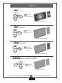
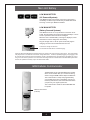
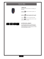
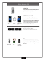
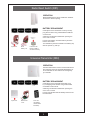
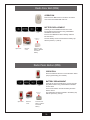
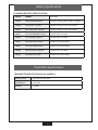
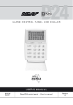
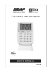
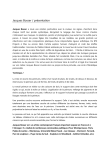
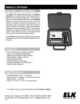
ElkGuard
TM
Self-Contained
Wireless Security System
ElkGuard
Owner's Manual
THIS MANUAL IS PROVIDED TO ACQUAINT YOU WITH THE OPERATION OF THE SYSTEM AND HELP YOU BECOME PROFICIENT WITH IT’S OPERATION.
ALL USERS SHOULD READ AND FOLLOW THE INSTRUCTIONS AND CAUTIONS IN THIS MANUAL. FAILURE TO DO SO COULD RESULT IN THE SYSTEM
NOT WORKING PROPERLY. KEEP THIS MANUAL IN AN EASY TO ACCESS LOCATION. READ AND FOLLOW THESE INSTRUCTIONS CAREFULLY. IF
YOU DO NOT UNDERSTAND ANY PORTION OF THIS MANUAL OR IF YOU HAVE ANY QUESTIONS ABOUT YOUR SYSTEM, CONTACT THE INSTALLING
COMPANY FOR ASSISTANCE.
System Notes
Installation Company: ___________________________________________________________________________________________
Address: ________________________________________________________ Phone Number: ________________________________
City: _________________________________________________________ St: __________ Zip: _____________
Central Monitoring Station: ___________________________________________________
Acct. # or ID _______________________
PLEASE BE AWARE OF THE FOLLOWING:
The level of security obtained is directly related to two major factors.
1. The placement of the main unit and the quantity and placement of any additional sensors that are a part of this system.
2. The knowledge and operating skills that you have of the system, including but not limited to the weekly testing of the complete system.
Important notes when preparing a security/safety plan for your home or business:
1. This system is an electronic device and is subject to failure or malfunction. You should not rely on it as your single source of security.
2. This system will operate on AC Power OR Internal Battery power, however it will not work without any power.
3. This system should be tested weekly.
4. Audible warning devices must be loud enough to provide adequate notification of an alarm event.
5. Only qualified security professionals should install and maintain this system.
FCC STATEMENT:
THIS DEVICE COMPLIES WITH PART 15 OF THE FCC RULES. OPERATION IS SUBJECT TO THE FOLLOWING TWO CONDITIONS: (1) THIS DEVICE MAY NOT
CAUSE HARMFUL INTERFERENCE, AND (2) THIS DEVICE MUST ACCEPT ANY INTERFERENCE RECEIVED, INCLUDING INTERFERENCE THAT MAY CAUSE
UNDESIRED OPERATION.
NOTE: THE MANUFACTURER IS NOT RESPONSIBLE FOR ANY RADIO OR TV INTERFERENCE CAUSED BY UNAUTHORIZED MODIFICATIONS TO THIS
EQUIPMENT. SUCH MODIFICATIONS COULD VOID THE USER'S AUTHORITY TO OPERATE THE EQUIPMENT.
This equipment generates and uses radio frequency energy and if not installed and used properly, that is, in strict accordance with the manufacturer's instructions, may cause Interference to radio and television reception. It has been type tested. However, there is no guarantee that interference will not occur in a
particular installation. If this equipment does cause interference to radio or television reception, which can be determined by turning the equipment off and on,
the user is encouraged to try to correct the interference by one or more of the following measures:
• If using an indoor antenna, have a quality outdoor antenna installed.
• Reorient the receiving antenna until interference is induced or eliminated.
• Move the receiver away from the security control.
• Move the antenna leads away from any wire runs to the security control
• Have the device or controller plugged into a different outlet so that it and the receiver are on different branch circuits.
If necessary, the user should consult the dealer or an experienced radio/television technician for additional suggestions. The user or installer may find a booklet
titled "Interference Handbook" prepared by the Federal Communications Commission helpful: This booklet is available from the U.S. Government Printing Office, Washington, DC 20402. The user shall not make any changes or modifications to the equipment unless authorized by the Installation Instructions or Users
Manual. Unauthorized changes or modifications could void the user's authority to operate the equipment.
ElkGuard Wireless Alarm System with GSM Communicator FCC ID: O2K-106058
Contains GSM/GPRS Modem Transmitter Module FCC ID: MIVGSM0108
Wireless Mini Door & Window Switch Transmitter (RR1) FCC ID: O2K-106064
Wireless Universal Transmitter w/ext input & Vib analyser (RR2) FCC ID: O2K-106065
Wireless 4 Button Keyfob Transmitter (RK4) FCC ID: O2K-106068
Wireless 3 Button Keyfob Transmitter (RK3) FCC ID: O2K-MK304
Wireless 1 Button Bracelet / Neckless Panic Transmitter (RK1) FCC ID: O2K-106050
Wireless Emergency Button Transmitter (RPB) FCC ID: O2K-106054
Wireless Door Bell Button Transmitter (RDB) FCC ID: O2K-106056
Wireless PIR with Pet Immunity (R15PET) FCC ID: O2K-106051
Wireless PIR - Non Pet Immune (R15) FCC ID: O2K-SPIR304
Swivel Mounting Bracket for Wireless PIR FCC ID: N/A
WARNING
Installation and maintenance shall be performed by qualified
service personnel only.
CAUTION
Risk of explosion if battery is replaced by an incorrect type.
Dispose of used batteries according to the instructions on
the battery.
Contact your local ElkGuard Dealer for all service.
For assistance in locating an ElkGuard Dealer in
your area contact:
Elk Products Inc.
PO Box 100
Hildebran, NC 28637
2
ElkGuard Main Unit
Congratulations on selecting ElkGuard.
The many sophisticated and innovative design
features of the ElkGuard make the system
highly secure as well as being easy to use.
Your ElkGuard with its "speak easy"
technology is a revolutionary, radio based,
state-of-the-art alarm system which has been
built to the highest standards of industrial
design and manufacturing.
This Owner's Manual will help you identify
the various parts of your ElkGuard system
and give you an overview of Operation and
functions.
Onboard Siren / Speaker
Siren and spoken voice prompts.
GSM Communicator
(Internal).
Rechargeable Main Battery
(Internal).
Scrolling LED Display
Indicator LED
One flash every 5 seconds indicates normal
operation.
Control Buttons
Left button
Right button
Adjust Main Volume - Press x 1
Main Volume 1 – 4
Adjust Bell Type - Press x 2
Bell Type 1 – 3
Adjust Bell Volume - Press x 3
Bell Volume 1 – 4 – OFF
Onboard Motion Sensor (PIR)
Emergency Over-Ride Keyswitch
3
Operation
Arm
button
Press once.
System is fully armed
Stay
(iF enabled)
button
Press twice.
System is partially armed
Stay2
(iF enabled)
button
Press three
times.
System is partially armed
Disarm (or to reset alarms)
button
Press once.
System is disarmed
In these examples, Armed areas are shown shaded
Disarmed areas are shown unshaded.
4
Operation
Panic Alarm
Alarm
button
Press & hold for
4 seconds.
GSM
Communicator
Central
Monitoring
Station
Clearing Displays
button
Press once.
To clear any display, press the Disarm
button. To recall the display, press
Disarm again (unless the display has
been reset by arming and disarming.)
Emergency Over-ride Key
Only to be used if your wireless Keyfobs are lost. Insert over-ride key and
turn counter-clockwise to disable the
ElkGuard. (Store these over-ride keys
in a safe, hidden place).
ElkGuard
power off
Turn the key counter
clockwise.
ElkGuard
power oN
Turn the key clockwise.
5
Main Unit Battery
LOW MAIN BATTERY
(AC Powered Systems)
If the ElkGuard has a permanent connection to AC power, a
low battery condition may indicate that your ElkGuard needs
servicing. Contact your ElkGuard installer.
LOW MAIN Battery
(Battery Powered Systems)
If the ElkGuard is not run off a permanent connection to AC
power, the main battery should provide approximately 3 or more
month's operation before it must be recharged.
Whenever the "Low Main Battry" message is displayed, it indicates that it is time to charge the main battery.
Plug the charger into a 110V AC power outlet and plug the
charging connector into the ElkGuard for 24 hours.
Connect the charger for 24 hours.
The red Indicator LED will be on while charging.
Important: Each time ElkGuard is plugged into the AC charger a 24 hr fast charge cycle is begun. The unit automatically drops back to a maintenance or "trickle" charge after 24 hrs . However, repeated plugging or unplugging of the
AC charger without sufficient time for the battery charge to be depleted may cause damage to the battery by overcycling it. For this reason, please do not connect the AC charger until the unit indicates a Low Main Battery OR unless
the unit has operated on battery only for at least several weeks.
GSM Cellular Communicator
The ElkGuard has an onboard GSM communicator
which communicates with your central monitoring
station using the GSM Cellular Telephone Network.
The communicator is setup and programmed by
your installer at the time of installation. It does not
need any maintenance, but should be tested when
you perform your regular system test.
The communicator needs an active GSM SIM card
to operate.
GSM Communicator
(Internal).
6
Keyfob (RK4)
Operation
RK4 Keyfobs have four buttons for operating your
ElkGuard.
Press the
button to Disarm the system or to
silence alarms.
Press the
button to Arm the system or press
twice for HOME mode (if enabled on your system.)
Press the
button to sound the Panic alarm.
Press the
button for auxiliary functions as programmed by your installer.
Battery Replacement
* Example device
number
Your RK4 Keyfobsadio Keys are sealed units with
an expected battery life of 10 years. Low battery
warning might indicate a battery fault or the battery
has been depleted by continuous presses. Contact
your ElkGuard dealer for advice.
7
Motion Sensors (PIR)
Operation
The R15 'Pet Immune' and R15 standard PIR motion
sensors can be added to the system to provide
protection in additional rooms.
Maximum detection range is 50ft.
Battery Saving Timer
The PIRs have a unique battery saving feature
which means you must wait 5 minutes between
activations.
Leave the
room.
Wait 5
minutes.
Red light
indicates motion
sensed.
To test a PIR, leave the room for at least 5 minutes
and then re-enter. The red light in the PIR will flash
to indicate that it has sensed your motion into the
room. If you don't see the red light you may not
have waited long enough - try again.
Battery Replacement
The R15 PIRs use an Ultralife U9VL 9V battery.
* Example device
number
R15
The R15 battery is inside the sensor. Carefully lift
off the sensor's cover by unsnapping at the bottom
using a flat-bladed screwdriver or blunt knife.
Unsnap cover
at the bottom.
Remove the
cover.
Insert the
new battery.
Ultralife U9VL
9V battery
Insert a new Ultralife U9VL 9V battery and then test
the sensor.
8
Radio Reed Switch (RR1)
Operation
Radio Reed Switches can be installed on windows
and doors to detect opening.
Battery Replacement
* Example device
number
Positive (+)
side up.
Carefully lift off the reed switch cover by unsnapping at the bottom using a flat-bladed screwdriver
or blunt knife.
A warning sound will be heard when opening the
case - this is normal.
Insert a new CR2477 3V Lithium battery and then
test the reed switch.
The new battery must be inserted in the battery clip
with the positive (+) side up.
Open here.
Slide
battery out.
Insert the new
battery. CR2477
3V Lithium battery.
Universal Transmitter (RR2)
Operation
Universal Transmitters can be used as window and
door switches (same as the Radio Reed Switch) or
as a transmitter for other devices as arranged by
your installer.
Battery Replacement
* Example device
number
Carefully lift off the Universal Transmitter cover
by unsnapping at the bottom using a flat-bladed
screwdriver or blunt knife.
A warning sound will be heard when opening the
case - this is normal.
Insert a new Ultralife U9VL 9V battery and then test
the transmitter.
Open here.
Remove the
cover.
Insert the
new battery.
Ultralife U9VL
9V battery
9
Radio Door Bell (RDB)
Operation
Press the Door Bell button to sound the sound the
door chime at the ElkGuard main unit.
Battery Replacement
* Example device
number
Carefully lift off the RDB Door Bell unit's cover
by unsnapping at the bottom using a flat-bladed
screwdriver or blunt knife.
Insert a new CR2032 3V Lithium battery and then
test the sensor.
Positive (+)
side up.
Open here.
Remove
cover.
The new battery must be inserted in the battery clip
with the positive (+) side up.
Insert the new
battery. CR2032
3V Lithium
battery.
Radio Panic Button (RPB)
Operation
Press the red Panic button to sound the Panic alarm.
(As programmed by your installer.)
Battery Replacement
* Example device
number
Carefully lift off the Panic Button's cover by unsnapping at the bottom using a flat-bladed screwdriver
or blunt knife.
Insert a new CR2477 3V Lithium battery and then
test the sensor.
Positive (+)
side up.
Open here.
Remove
cover.
The new battery must be inserted in the battery clip
with the positive (+) side up.
Insert the new
battery. CR2477
3V Lithium
battery.
10
Battery Specifications
ElkGuard Battery Specifications
Part #
Model
Battery
106058
ElkGuard Main Unit
Elk1233 12V 3Ah Sealed Lead Acid Battery
106068
RK4 Keyfob - 4 button
Sealed housing, not user serviceable
106050
RK1 Radio Panic Pendant
Sealed housing, not user serviceable
106051
R15 'Pet" PIR Motion Sensor
Ultralife U9VL 9V battery
106062
R15 PIR Motion Sensor
Ultralife U9VL 9V battery
106054
RPB Radio Panic Button
CR2477 3V Lithium battery
106064
RR1 Radio Reed Switch
CR2477 3V Lithium battery
106065
RR2 Universal Transmitter
Ultralife U9VL 9V battery
106056
RDB Radio Door Bell
CR2032 3V Lithium battery
Transmitter Specifications
Transmitter Specifications (All Models)
Modulation
100% AM (On Off Keyed)
Frequency
303.85 Mhz
Power
< 10uW
11
ElkGuard Owner's Manual
Revision Oct 2007
Copyright Notice
All rights reserved. No part of this publication may be reproduced, transmitted or stored in a retrieval system in any form or by any means, electronic,
mechanical, photocopying, recording, or otherwise, without the prior written permission of Elk Products.
Elk reserves the right to make changes to features and specifications at any time without prior notification in the interest of ongoing product development
and improvement.
© 2007 Elk Products, Inc.