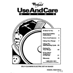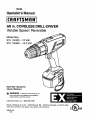
1
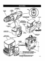
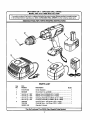
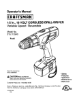
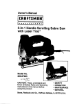
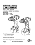
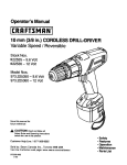
_l, Ryobi
!I
I
Operator's Manual
I:RRFTSMRN'I
318 in. CORDLESS
DRILL-DRIVER
Variable Speed / Reversible
Model Nos.
315.11452012 Volt
315.114530 - 14.4 Volt
Save this manual for
future reference
WARNING:
ToreducetheriskofInjury,the
user must read and understand the operator's
manual before using this product.
Customer
Help Line: 1-800-932-3188
Sears, Roebuck
and Co., 3333 Beverly
Rd., Hoffman
Visit the Craftsman web page: www.sears.com/craftsman
983000-182
2-03
Estates,
IL 60179
USA
0( us
•
Table of Contents ...........................................................................................................................................................
2
•
Warranty .........................................................................................................................................................................
2
•
Introduction .....................................................................................................................................................................
3
•
General Safety Rules, Specific Safety Rules, and Symbols ......................................................................................
•
Product Specifications
•
Features .....................................................................................................................................................................
•
Operation ..................................................................................................................................................................
•
Malnterk_nos .................................................................................................................................................................
15
•
Aosessorles
15
•
Exploded View and Repair Parts List ...........................................................................................................................
17
•
Parts Ordering / Servlos ...............................................................................................................................................
18
3-6
....................................................................................................................................................
7
7-8
9-14
..................................................................................................................................................................
FULL ONE YEAR WARRANTY
ON CRAFTSMAN
3/8 in. CORDLESS
DRILL-DRWER
ff this [RRFTSNRN 3/8 in. Cordless DdlI-Ddver falls to give complete satisfaction within one year from the date of purchase, RETURN IT TO THE NEAREST SEARS STORE OR SEARS SERVICE CENTER IN THE UNITED STATES,
and Sears will repair it, free of charge.
ffthis I:IIRFTSNRN 3/B In. Cordless DrllI-Drlvar Is used for commercial or rental purposes, this warranty applies for only
90 days from the date of purchase.
This warranty gives you specific legal rights, and you may also have other rights which vary from state to state.
Sears, Roebuck
and Co., Dept. 817WA,
Hoffman Eatates,
IL 60179
_1= Look for this symbol to point out Important
attention!!! Your safety is involved,
safety precautions.
It means
AWARNING:
O
The operation of any powertool can result In foreign objectsbeing thrown Into your eyes, which can
result
Insevereeye damage, Beforebeginning
powertooloperation,
alwayswear safety
gogglesor
safety
glasseswithsideshields
and a full
faceshleld
when needed.We recommend Wide Vlslon
SafetyMask foruse overeyeglasses
orstandardsafety
glasseswlthsldeshlelds,
available
atSears
Retail
Stores.
Alwayswear eye protection
whichismarkedtocomplywlthANSI Z87.1,
SAFETY AND INTERNATIONAL
SYMBOLS
This operator'smanual describes safety and Internatloeal symbolsand pIctographsthat may appear on _his product,
Read the operator'smanual for complete safety, assembly, operatingand mainter_nce, and repair information,
MEANING
Do not expose to rain or use in damp locations.
Your drill-driverhas many features for making yourdrilling
operationsmore pleasant and enjoyable. Safety,
performanceand dependabilityhave been given top
priorityin the design of this drill-drivermaking it easy to
maintain and operate.
_kWARNING:
Reed and understand all Inatructlons.
Failure to follow all instructionslistedbelow, may
resultin electric shock,fire and/or seriouspersonal
Injury.
WARNING:
Do not attempt to use this product until
you read thoroughly and understand completely the
operator's manual. Pay close attention to the safety
rules including Dangers, Warnings and Cautions. If
you use this pn:x:lustproperly and only as Intended,
you will enjoy yearn of safe, reliable service,
Personal Safety
•
SAVE THESE INSTRUCTIONS
Work Area
•
Keep your work area clean and well lit. Cluttered
benches and dark areas Invite accidents.
Do not operate power tools in _ploafve
atmospheres, such as in the presence of flammable
liquids, gases, or duet. Power tools create sparks
which may Ignite the dust or fumes,
•
Keep bystanders, children, and visitors away while
operating a power tool. Distractions can cause you
to lose control
•
•
•
Remove adjusting keys or wrenches before turning the tool on, A wrench or a key that Is left attached
to a rotating part of the tool may result in personal
Injury,
•
Do not overreach. Keep proper footing and balance at all tlmee. Proper footing and belanos enables
better centre1 of the tool in unexpected situations. Do
not use on a ladder or unstable support,
•
Use safety equipment. Always wear aye protection.
Dust mask, nonskid safety shoes, hard hat. or hearing
protection must be used for appropriate conditions,
Electrical Safety
•
•
Do not abuse the cord. Never use the cord to carry
the charger. Keep curd away from heat, o11,sharp
edges, or moving parts. Replace damaged cords
Immediately.
Damaged cords may create afire.
A battery operated tool with Integral batteries or a
separate battery pack must be recharged only with
the specified charger for the battery. A charger that
may be suitable for one type of battery may create a
dsk of fire when used with another battery. Use battery
only with charger listed.
MODEL
BATTERY PACK CHARGING ASSEMBLY
315.114520
ITEM NO.S 11057
ITEM NO. _)11055
(1322549)
(1425004)
315,114530
ITEM NO. it 11044
ITEM NO. _ 11041
(1322522)
(1425301 )
Use battery operated tool only with specifically
designated battery pack. Use of any other batteries
may create a risk of fire. Use only with battery pack
listed,
Stay alert, watch whet you are doing and use
common sense when operating a power tool. Do
not use tool while tired or under the Influence of
drugs, alcohol, or medication. A moment of inattention while operatingpower toolsmay result In serious
personal Injury.
Dress propedy. Do not wear loose clothing or
Jewelry.Contain long hair. Keep your hair, clothing,
and gloves away from moving parts. Loose clothes,
jewelry, or long haircan be caught In moving parts
Avoid accidental starting. Be sure switch Is In the
locked or nff position b_ore Inserting battery
pack. Carryingtoolswith yourfinger on the switchor
insertingthe bat:terypack intoa tool with the switchon,
Invitesaccidents
Tool Use and Care
•
•
•
•
•
•
Use clamps or other practical way to secure and
support the workplace to a stable platform. Holding
the work by hand or against your body Is unstable and
may [sadto loss of control.
Do not fame tool. Use the correct tool for your
application. The correcttool will do the job Petterand
safer at the rate for which it is designed.
no not use tool if switch does not turn it on or off.
A tool that cannot be controfled with the switchis
dangerousand must be repaired.
Dlsconnentbattery'pack from tool or placethe switch
in the locked or off pnelion beforemakingany adjustmerits, chenglng accessories,or ,_odug thetooL Such
preventives,_etymeasuresreduce_k of maz_r_thet_x_
accidentally.
Store Idle tools out of reach of children and other
untrained persons. Tools aredangerousinthe hands
of untrained users.
When battery pack Is not In use, keep it away from
other metal objects like: pager clips, coins, keys,
nails, screws, or other small metal objects that can
make a connection from one terrnlnal to another.
Shafting the battery terminals together may cause
sparks, burns,or a fire.
•
•
•
Maintain tools with care. Keep cutting tools sharp
and clean. Properlymaintainedtools, with sharp
cuttingedges are less I[keiyto bind and are easier to
control.
Check for mlulignment or binding of moving pads,
breakage of parts, and any other condition that may
_fect the tool's operation"If damaged, have the tool
serviced before using. Many accidents are caused by
poodymaintainedtools.
Use only aecesserles that are recommended by
the manufacturer for your model. Accessoriesthat
may be suitablefor one tcol, may create a risk of injury
when used on anothertool.
Service
•
•
Tool servile must he pedormnd only by qualified
repair personnel. Service or malntenanse performed
by unqualified personnel could result in a ask of injury.
When servicing a tool, use only identical replacement parts. Follow instructions in the Maintenance
section of this manual. Use of unauthorized parts or
failure to follow Maintenance Instructions may create a
risk of shock or injury,
Hold tool by insulated gripping sudaces when performing
an operation where the cutting tool may contact hidden
wiring. Contact with a "live" wire will make exposed metal parts of the tool "live" and shock the operator,
Additional
•
•
For Safe
Operation
Know your power tool. Read operator's manual
carefully. Learn Its applications and limitations, as
well as the specific potential hazards related to
this tool. Following this rule will reduce the risk of
electric shock, tim, or serious Injury.
Make sure your mdension cord is in good condition,
When using an e0dension cord, he sum to use one
heavy enough to carry the cutrerd your product will
draw. A wire gage size (A.W.G,) of at least 16 Is
recommended for an extension cord 100 feet or less
In length. A cord exceeding 100 feet Is not recommended. If in doubt, nee the ne0d heavier gage. The
smaller the gage number, the heavier the cord. An
undersized cord will cause a drop In line voltage resulting in loss of power and overheating.
Important
•
Rules
Rules
for Battery
Tools
Battery tools do not have to be plugged Into an
electrical outlet; therefore, they are always in
operating condition" Be aware of possible hazards
when not using your battery tool or when changIng accessories. Following this rule will reduce the
risk of electric shock, fire, or serious personal Injury.
•
•
•
•
•
Do not place battery tools or their batteries near
fire or heat. This will reducethe risk of explosion and
possible Injury.
Bettedesvent hydrogengas and can explode in the
presenceof a sourceof Ignition, such asa pilot light.
To reduce the risk of sedous personalinjury, never
use any cordless productIn the presence of open
flame. An exploded battery can propeldebris and
chemicals. If exposed, flushwith water Immediately.
Do not charge battery tool In a damp or wet
location. Followingthis rulewill reduce the dsk of
electdc shock.
For best rexuits, your battery tool should be
charged In a location where the temperature is
more than 50°F but less than IO0°F. Do not store
outside or In vohlclex.
Under extreme usage or temperature conditions,
battery leakage may occur. If liquid comes In
contact with your skin, wash Immediately with
soap and water, then neutralize with lemon juice
or vinegar. If itquld gets into your eyes, flush them
with clean water for at least 10 minutes, then seek
Immediate medilal attention. Followingthis rule will
reduce the dsk of seriouspersona.I Injury.
•
Neverusea battery that has been dropped or received a sharp blow. A damaged battery Is subjectto
explosion, Properlydispose of a dropped battery
immediately.Failure to heed this warning can resultIn
serious personal injury.
•
Do not operate charger I! It has received a sharp
blow, been dropped, or otherwise damaged in any
way; take it to a qualified serviceman. FolioNIng
this rule will reduce the risk of electric shock, fire, or
sedous personal Injury.
•
Before using battery charger, read all instructions
and cautionary markings In this manual, on
battery charger, and product using battery
charger. Followingthis rule will reduce the risk of
electric shock,fire, or serious personal Injury,
•
•
To reduce risk of injury, charge only nickelcadmium and nickel metal hydride type rechargeable batteries. Other types of batterlse may burst
causing personal injury and damage. Followingthis
rule will reducethe risk of electric shock,fire, or
serious persona] Injury.
Do not disassemble charger;, take it to a qualified
serviceman
when service or repair is required.
Incorrect reassembly
may result In a dsk of
electdc shock or fire. FollowLnclthis rule will reduce
the risk of electric shock, fire, or serious personal
injury.
•
To reduce the dsk of electric shock, unplug
charger from outlet before attempting any maintenance or cleaning. Turning off controls will not
reduce this risk. Following this rule will reduce the
risk of electric shock, fire, or serious personal Injury.
•
Do not use charger outdoors. Following this rule will
reduce the risk of e]ectrlc shock, fire, or serious
personal Injury.
•
Disconnect charger from power supply when not
in use. Following this rule will reduce the risk of
electdc shock, fire, or serious personal Injury.
•
RISK OF ELECTRIC SHOCK. DO NOT TOUCH
UNINSBLATED PORTION OF OUTPUT CONNECTOR OR UNINSULATED BAI"rERY TERMINAL.
•
•
Do not expose charger to rain or snow. Following
this rule will reduce the dsk of electric shock, fire, or
serious personal Injury.
Use of an attachment not recommended or sold
by the baUery charger manufacturer
may result In
a risk of fire, electric shock, or Injury to persons.
Following this rule will reduce the risk of electrlc
shock, fire, or serious personal Injury.
•
•
•
To reduce riskof damagers
charger body and
cord, pull by charger plug rather than cord when
disconnecting charger. Following this rule will
reduce the risk of electric shock, fire, or serious
personal injury.
Make sure cord Is located so that It will not be
stepped on, tdpped over, or otherwise subjected
to damage or stress. Following this rule wilFreduce
the risk of serious personal injury.
An extension cord should not be used unless
absolutely necessary.
Useof Improper extension
cord could result in a risk of fire and electric shock. If
extension cord must be used, make sure:
a. That pins on plug of extension cord are the
same number, size and shape as those of
plug on charger.
b. That extension cord is properly wired and In
good electrical condition; and
c. That wire size Is large enough for AC ampere
rating of charger as specified below:
Cord Length (Feet] 25'
50'
100'
Cord Size (AWG)
16
16
16
Note: AWG = American Wire Gage
•
Do not operate charger with a damaged cord or
plug. ff damaged, have replaced Immediately by a
qualified serviceman. Following this rule will reduce the
risk of electric shock, fire, or serious personal Injury.
Save these Instructions. Refer to them frequently
and usa them to instruct others who may use this
tool. If you loan someone this tool, loan them
these instructions also. Followingthis rule will
reduce the risk of electricshock, fire, or serious
personal Injury.
_kWARNING:
Some dust created by power sanding,
sawing, grinding, drilling,and other construction
activities contains chemicals known to cause
cancer, birth defects or other reproductive harm.
Some examples of these chemicals are:
• lead from lead-based paints,
• crystalline silica from bricks and cement
and other masonry products, and
• arsenic and chromiumfrom chemicallytreated lumber.
Your risk from these exposures varies, depending
on how often you do this type of work. To reduce
your exposure to these chemicals: work in a well
ventilated area, and work with approved safety
equipment, such as those dust masks that are
specially designed to filter out microscopic particles.
Important: Some of the following symbols may be used on your tool. Please study them and learn their meaning. Proper
interpretation of these symbols will allow you to operate the tool better and safer.
SYMBOL
NAME
D ESIG NATION/F..X PLAN ATIO N
V
Volts
Voltage
A
Amperes
Current
Hz
Hertz
Frequency (cycles per second)
min
Minutes
Time
Alternating Current
Type or a characteristic of currant
--=
D]rect Current
Type or a charautadstic of current
no
No Load Speed
Rotational speed, at no load
Revolutions or Reciprocation Per Minute
Revolutions, strokes,
surface speed, orbits etc. per minute
Safety Alert Symbol
Indicates danger, warning or caution.
It rn_ans attention!l! Your safety is
Involved.
.../rain
Wear Eye Protection
O
glasssswlth side shleldsand a full face
Always wear safety goggles or safety
shield when operating this product.
The purpose of safety symbols is to attract your attention to possible dangers. The safety symbols, and the
explanations with them, deserve your careful attention and understanding. The safety warnings do not by themselves
eliminate any danger. The Instructions or warnings they give are nct substitutes for proper accident prevention
measures.
Symbol
A
A
A
NOTE:
Meaning
DANGER: Indicates an imminentlyhazardous situationwhich, If not avoided, will result In death or
sedous injury.
WARNING:
Indicates a pcXentlally hazardous situation which, if not avoided, could result in death or
sadous Injury.
CAUTION:
Indicates a botentlally hazardous situation which, If not avoided, may result in minor or
moderate injury. It may also be used to alert against unsafe practices that may cause property damage.
Advises you of information or instructions vital to the operation or maintenance
SAVE THESE INSTRUCTIONS
of the equipment.
DRILL-DRIVER
Chuck
Motor
Gear Train
Switch
No Load Speed
Clutch
Maximum Torque
CHARGING
ASSEMBLY
Rating
Charging Voltage
Charge Rate
BATTERY
PACK
• Craftsman
315.114520
3/8 In. Keyless
DC Motor 12 Volt
Two Speed
Variable Speed
0-300 RPM (Low)
O-1000 RPM (High)
24 Positions
225 In,lb.
Item No. =11055
(1425004)
1 20 V, 60 Hz, AC only
12 Volt
3-6 Hours
Item No. !11057
(1322549)
315.114530
3/8 in. Keyless
DC Motor 14.4 Volt
Two Speed
Vadabls Speed
0-400 RPM (Low)
0-1400 RPM (High)
24 PoslUons
275 In,lb.
Item No. !11041
(1425301)
120 V, 60 Hz, AC only
14.4 Volt
1 Hour
Item No. !11044
(1322522)
EX 114520 - 12V test criteda
225
280
150
In,]b. torque
#5 x 1,25 in, wood screws In low speed per battery pack charge Into pine lumber.
3/8 In. diameter holes par battery pack charge into 2 in. nominal pine lumber,
Craftsman
EX 114530 - 14.4V test criteria
275
I
in,lb. torque
170
220
I
3/8
diameter
holes
per battery
peck cherge
Into 2pack
In. nominal
lumber.
#8 xIn,
1.25
in. wood
screws
In low speed
per battery
charge pine
Into pine
lumber,
KNOW YOUR DRILL-DRIVER
See Figure 1.
Before attempting to use your drill-driver,familiarize
yourselfwith all operating features and safety
requirements.
KEYLESS CHUCK
Your drill-driverhas a keylesschuck that allowsyou to hand
tighten or release drillbit Inthe chuckjaws,
SWITCH
To turn your drill-driverON, depressthe switchtrigger,
Release switchtriggerto turn your drill-driverOFF.
SWITCH LOCK
The switch trigger nan be lockedin the OFF position.This
feature helps reduce the possibility of accidental starting
when not In use,
VARIABLE
SPEED
This tool has a variab[e speed switch that delivers higher
speed with Increased tdgger pressure. Speed is controlled
by the amount of switch trigger depression.
TWO SPEED GEAR TRAIN
Your drill-driver has a two speed gear train designed for
drilling or driving at HI or LO speeds. A slide switch is
located on top of your drill to select either HI or LO speed,
FORWARD/REVERSE
SELECTOR
(DIRECTION OF ROTATION SELECTOR)
Yourdrill-driverhas a forward/reverseselectorlocated
above the switch trigger.
WRIST STRAP
A wrist strap is provided to reducethe chances of dropping
your dril!-driver,Place one handthrough the wdststrap
when carryingtool.
BIT STORAGE
When not In use, bit(s) providedwith your drill-drivercan
be placed In the storage area located on the bottomof the
motor housing.
LEVEL
To keep drill bit level duringddlllngoperations,a level Is
locatedon the back of the motorhousing.
,_
WARNING: ff any partsate missing,do not operate
yourdrill-driveruntil the missingpartsare replaced.
Failureto do so couldresultIn possiblessdous
personal Injury.
TWO-SPEED
GEARTRAIN(HI&O)
LEVEL
TORQUE
ADJUSTMENT
RING
KEYLESS
CHUCK
BATFERYPACKSHOWN
IN CHARGING
STAND
CHARGER
REARVIEW
DIRECTION
OF
ROTATION
SELECTOR
(FORWARD/REVERSE)
SWITCH
TRGGER
RED UGHT
(LED)
SCREWDRIVER
BATTERYPACK
SHOWN
DIT
STORAGE
CHARGERSTAND
315,114520
BATTERY PACK
SHOWN IN CHARGER
WRIST STRAP
CHARGER
315.114530
4-1/2In,
' CYCLE,INDICATESFULLYCHARGEDBA'n'ERY
PACK ANDIN TRICKLE CHARGEMODEL
YELLOWAND GREENLEDSON INDICATESDEEPLY
DISCHARGEDOR DEFECTIVEBATTERYPACK.
8
Fig. 1
_
_
WARNING : Always wear safety gogglesor safety
glasses with side shields when operatingtools.
Failure to do so could result In objects being thrown
intoyour eyes, resultingin possible sedousinjury,
WARNING: 0o not allow famillahtywith yourdrilLdriver to make you careless, Remember thet a
careless fraction of a second Is suffic[ertto inflict
severe injury,
BATTERY PACK
(MODEL
315.114520)
The battery pack for your tool has been shipped in alow
charge condition to prevent possible problems.
Therefore, you should charge It overnight prior to use,
Note; Batteries will not reach full charge the firs[ time they
are charged, Allow several cycles (drilling followed by
recharging) for them to become fully charged,
CHARGING
BATTERY
PACK
(MODEL 315.114520)
See Figure 1.
•
Charge battery pack only with the charging assembly
provided.
•
Make sure power supply Is normal household
voltage, 120 voits, 60 Hz, AC only.
•
Connect charger to power supply,
•
Place battery pack in charging stand, Align raised fib
on battery packwlth groove [n charging stand.
See Figure 1.
•
Press down on batte_ pack to be sure contacts on
battery pack engage properly with contacts In charg]ng
stand.
The charge Indicator light (LED), located on the
charging stand, will light up red and glow when the
charger is properly connected to power supply. This
light Indicates the charger is operating properly, It w]ll
remain on until battery pack Is removed from charging
stand or charger is disconnected from power supply,
•
Note: If charger does not charge battery pack, return
battery pack and charging assembly to your nearest
Sears Repair Center for electrical check.
•
After normal usage, a 3 hours or less of charging time
Is required to fully recharge battery pack, Note: If
battery pack Iscompletely discharged, 6 hours or
longer of charging time Is required to fully recharge
battery pack,
•
The battery pack wl[I become slightly warm to the
touch while charging. This is norn'_l and does not
Indicate a problem,
•
0o not place charger in an area of extreme heat or
cold, It will work best at normal room temperature,
•
When batteries become lully charged, unplug charger
from power supply and remove the battery pack.
IMPORTANT INFORMATION
HOT BATTERIES
FOR RECHARGING
(MO DEL 315.114520)
When usLng your
your battery pack
battery pack cool
before attempting
drill-driver continuously, the batteries in
will become hot. You should let a hot
down for approximately 30 minUtes
to recharge.
Note: This situation only occurs when continuous use of
your drill causes the batteries to become hot. It does nat
occur under normal circumstances. Refer to "CHARGING
BATTERY PACK" for normal recherglng of parterres. If
the ch_ging assembly does nat charge your battery pack
under normal circumstances, return both the battery pack
and charging assembly to your nearest Sears repair
center for electrical check.
A
LED FUNCTIONS OF CHARGER
LED WILL BE ON TO INDICATE STATUS OF
CHARGER AND BATTERY PACK: (MODEL
315.114520)
WARNING:
Do not allow familiarity with your drilldriver to make you careless. Remember that a
careless fraction of a second is sufficient to inflict
severe injury.
BATTERY
PACK
(MODEL 315.114520)
The battery pack for your tool has been shipped In a low
charge condition to prevent possible prebiems. Therefore,
you should charge it until light on front of charger changes
from red to green.
Note: Batteries will not reach full charge the first time they
are charged. Allow several cycles (drilling followed by
recharging) for them to become fully charged.
CHARGING
BATTERY
•
•
•
•
•
•
•
•
•
•
Red LED on = Fast charging mode.
Green LED on = Fullycharged and [ntricklecharge
mode.
•
Green LED on = When batterypack Is InsettedInto
charger, Indicateshot battery pack or that battery pack
Is out of or below normal temperature range.
Yellowand Green LEDs on = Deeplydischargedor
defective battery pack.
No LED on = Defective charger or battery pack.
•
•
PACK
_i,
(MODEL
315.114520)
See Figure 1.
•
•
•
•
Charge battery pack only with the charger provided.
Make sure power supply is normal household
voltage, 120 volts, 60 Hz, AC only.
Connect charger to power supply.
Place battery pack in charger aligning raised rib on
battery pack with groove in charger. See Figure 1.
Press down on battery pack to be sure contacts on
battery pack engage properly with contacts in charger.
Normally, the red LEE) on charger will come on. This
indicates charger is [n fast charging mode,
Red LED should remain on for approximately 1 hour
then the green LED will come on. Green LED on
Indicates battery pack Is fully charged and charger is In
trickle charge mode. Note: Green LED will remain on
until batten/pack Is removed from charger or charger
Is disconnected from power supply.
If both yellow and green LED come on, this Indicates a
deeply discharged or defective battery pack.
Allow battery pack to remain in charger for 15 to 30
minutes. When battery pack reaches nern'_l voltage
range, red LED should come on.
If red LED does not come on after 30 minutes, this
indicates a defective battery pack and should be
replaced.
Alter normal usage, a minimum of 1 hour of charging
time is required to fully recharge battery pack.
The battery packwill become slightly warm tothe
touch while charging. This is normal and does not
indicate a problem.
Do not place charger and battery pack In an area of
extreme heat or cold. It will work best at normal room
temperature.
Note; Charger aho battery pack should be placed in a
location where the temperature is more than 50°F but
less than 100°F.
CAUTION: To prevent damage to battery pack,
remove battery packfrom charger Immediately if no
LED comas on. Return battery pack and charger to
your nesrest Sears Service Center for checldngor
rep[ec]ng.A[so, If you are removing battery pack from
charger and no LEDs are on, return both batterypack
and charger to your nearest Sears Service Center.
Do not Insertanother battery pack intocharger. A
damaged charger may damage a battery pack.
IMPORTANT INFORMATION
HOT BATTERY PACK
FOR RECHARGING
When using your drill-driver continuously, the pattedes in
your battery pack will become hot. You should let a hot
battery pack cool down for apprexlmately 30 minutes
before attempting to recharge. When the battery pack
becomes discharged and Is hot, this will cause the green
LED to come on instead of the red LED. Alter 30 minutes,
reinsert battery pack in charger, ff green LED continues to
remain on, return battery pack to your nearest Sears
Repair Center for checking or repleclng,
Note; This situation only occurs when continuous use of
your drill causes the batteries to become hot. It does not
occur under normal circumstances. Refer to "CHARGING
BAI-rERY PACK" for normal recharging of batteries. If
the charger does not charge your battery deck under
normal circumstances, return both the battery pack and
charger to your nearest Sears Repair Center for electrical
check.
IMPORTANT INFORMATION
COOL BATTERY PACK
FOR RECHARGING
If battery pack Is below normal temperature range, the
green LED on charger will come on. Allow battery pack to
reach normal temperature, than the red LED will coma on.
Note', Refer to "CHARGING BATTERY PACK" for
normal recharging of batteries, If the charger does not
charge your battery pack under normal circumstances,
return both the battery pack and charger to your nearest
Sears Repair Center for electrical check.
When batteries become fully charged, unp[ug charger
from power supply and remove the battery pack.
10
SWITCH
See Figure 2.
TO INSTALL BATI'ERY
RI Lockswitchtflggeronyourdrlll by placing the direction
of rotationselectorIn center position,See Figure 5.
• Place battery peck In your drill. Align raised fib on
battery pack with groove insideddll. See Figure 4.
To turn your drillON, depress the switchtdgger. To turn It
OFF, release the switch trigger,
SWITCH
TRIGGER
VARIABLE
PACK
Fig. 2
SPEED
BATTE_
___TCHES
This tool has a variable speed switch that delivers higher
speed and torque with increased trigger pressure. Speed is
controlled by the amount of switch trigger depression.
Note: You might hear a whistling or dnglng noise from the
switch dudng use. Do not be concerned, this Is a normal
part of the switch function,
TWO-SPEED
See Figure 3.
GEAR
TRAIN
Your drill has a two-speed gear train designed for drilling
or driving at LO (1) or HI (2) speeds, A slide switch is
located on top of your drill to select either LO (1) or HI (2)
speed, When using drill In the LO (1) speed range, speed
will decrease and unit will have more power and torque.
When using drill In the HI (2) speed range, speed will
Increase and unit will have less power and torque. Use
LO (1) speed for high power and torque applications and
HI (2) speed for fast ddlllng or driving applications.
TWO SPEED
GEAR TRAIN (HI-LO)
RELEASEBATTERYPACK
•
A
LO
SPEED
Fig, 4
Make sure the latches on each side of your battery
pack snap In place and battery pack is secured in drill
before beginningoperation.
CAUTION: When placingbattery pack In your drill,
be sure raised rib on battery pack aligns with groove
insidedrilland latches snap into place properly.
Improperassembly of battery peck can cause
damage to Internalcomponerts.
TO REMOVE BAI"FERY PACK
SPEED
•
•
•
Fig. 3
11
Lock switchtriggeron your ddll by placingthe direction
of rotationselector in center position. See Figure5.
Locate latches on side of battery pack and depress to
release battery pack from your drill. See Figure 4,
Remove battery pack from your dflll.
SWITCH LOCK
KEYLESS CHUCK
See Figure 5,
See Figure 6.
The switch trigger can be locked In the OFF position. This
feature can be used to prevent the possibilityof accidental
starting when not In use. To lock switch tdgger, place the
directionof rotation selector (Forward/Reverse Selector)
in center position.
Yourdrillhas a le_ylesschuck,As me name implies,you can
hand tighten or releaseddl]bits in the chuckjaws. Graspand
ho4dthe collarofthe chuckwith one hand.Rotate the chuck
bodywithyourother hand.The an-owson the chuck
Indicatewhichdirectionto rotatethe chuck bodyIn orderto
LOCK (tighten) or UNLOCK (release) the drillb_t.
SELECTORWITH
CENTER LOCK POSITION
REVERSE
UNLOCK
(RELEASE)
CHUCK
COLLAR
DRILLBIT
FORWARD
SWITCH
TRIGQER
CHUCKJAWS
Fig. 5
LOCK
mGHTE_
WARNING:
Battery tools are always In operating
condition. Therefore, switch should always be locked
when not In use or carrying at your side.
FIg. 6
REVERSIBLE
_lb WARNING : Do not hold chuck body with one hand
and use powerof the drillto tightenchuck Jaws on
drillbit. Chuck body could slip In your hand or your
hand could slipand come in contact with rotatingdrill
bit. This could cause an accidentresulting in sedous
personal Injury.
See F/gum 5.
This tool has the feature of being reversible. The direction
of rotation is controlled by a se]ector located above the
switch trigger. With the drill held In normal operating
position, the direction of rotation selector should be
positioned to the left of the switch for drilling. The drilling
direction is reversed when the selector is to the right of
the switch. When the selector is in center position, the
switch trigger is locked.
_k
CHUCK
BODY
CAUTION: To prevent gear damage, always al]ow
chuck to come to a complete stop before changing
the directionof rotation.
To stop, release switch trigger and allow the chuck to come
to a complete stop.
12
INSTALLING
See Figure 7.
REMOVING BITS
BITS
See Figure Z
•
Lock the switch trigger by placing the direction of
rotation selector in center position, See Figure 5,
•
Lock the switch trigger by placing the direction of
rotation selector in center position. Sea Figure 5.
•
Open or close chuck jaws to a point where the opening Is slightly larger than the bit size you intend to use.
Also, raise the front of your drill slightly to keep the bit
from falling out of the chuck Jaws.
•
Loosen the chuck Jaws from drill bit.
•
To loosen: grasp and held the collar of the chuck with
one hand, while rotating chuck body wtth your other
hand, Note: Rotate chuck body in the direction of the
arrow marked UNLOCK to loosen chuck Jaws.
•
Insert drill bit stre(ght Into chuck the full length of the
jaws as shown in Figure 7.
•
Tighten the chuck Jaws on ddll blL
UNLOCK
(RELEASE)
•
Do not use a wrench to tighten or loosen the chuck
JAWS,
•
CHUCK
COLLAR
Remove drill bit from chuck Jaws.
ADJUSTABLE
DRILLBIT
TORQUE CLUTCH
Your ddll is equipped with an adjustable torque clutch for
driving different types of screws into different materials,
The proper setting depends on the type of material and the
size of screw you are using,
TO ADJUST TORQUE
CHUCK
JAWS
,_
5- 8
LOCK
CHUCK
(TIGHTEN)
BODY
RIGHT
•
•
Identify the twentyfour torque Indicatorsettingslocated
on the front ofyour drill. See Figure 9,
Rotate adjusting ringto the desired setting.
• 1- 4
For drivingsmall screws.
• 9-12
For driving screws intosoft and hard
materials.
For drivingscrews In herd wood.
Fig. 7
,13-16
To tighten the chuck jaws on drill bit; grasp and hold
the collar of the chuck with one hand, while rotating
the chuck body with your other hand.
• 17-
For drivingscrewsinto sott
matedal.
20
For drivinglarge screws.
' 24 - 4Ll_l For heavy drilling.
Note: Rotate the chuck body In the direction of the
arrow marked LOCK to tighten chuck Jaws.
Do not use a wrench to tighten or loosen the chuck
Jaws.
TO DECREASE
TORQUE
ADJUSTING
RING
A
WARNING: Make sure to insert:drill bit straightinto
chuckJaws. Do not Insert drill bit Intochuck Jaws at
an angle then tighten, as shown in Figure 8, This
could cause drill bit to be thrown from drill, resulting
in possibleserious personal injuryor damage to the
chuck,
TO INCREASE
TOROUE
Fig. B
13
Fig, 9
BITSTORAGE
DRILLING
See Figure 10.
See Figure 12.
When not in use, bits provided with your drill can be
placed in the storege area located on the bottom of your
drill as shown in Figure 10,
BI1
STORAGE
AREA
Fig. 10
_k
WARNING; Always wear salaty goggles or safety
glasses with side shields when operating tools,
Fig. 12
Fal]ureto do so could resultin objects being thrown
Intoyour eyes, resultingIn possibleseriousInjury.
When drillinghard smooth surfacesuse a center punch to
mark desired hole location.This will prevent the drill bit
from slippingoffcenter as the hole is started.However,
the low speed feature allows starting holes withoutcenter
punchingff desired. To accomplishthis, simplyoperate
your drill at a low speed untilthe hole Is started.
The material to be drilled shouldbe secured in avlse or
with clampsto keep it from turning as the drillbit rotates.
LEVEL
See Figure 11.
A convenient feature provided with your ddll Is a level, It
is recessed in the motor housing on back of your drill, It
can be used to keep drill bit level during drilling operations,
REARVIEW OF DRILL
Hold tool firmly and place the bit at the pointto be drilled.
Depress the switchtriggerto start tool.
Move the drill bit into the workplece applying only enough
pressure to keep the bit cutting, Do not force or apply side
pressure to elongate a hole.
LEVEL
A
WARNING:
Be prepared for binding or bit
breakthrough. When these situations occur, drill has
a tendency to grab and kick opposite to the direction
of rotation and could cause loss of control when
breaking through matedaL If not prepared, this loss
of control can result in possible serious injury,
When drillingmetals, use a light oll on the drill bitto keep
it from overheating.The ollwill prolongthe life ofthe bit
and increase the drillingaction.
Fig, 11
If the bit JamsIn workplece or Ifthe drill stalls, release
switchtrigger Immediately.Remove the bitfrom the
workplece and determinethe reason for jamming.
14
CHUCK REMOVAL
•
See Figures 13, 14, and 1.5.
The chuck must be removed In order to use some
aGcessories. To remove:
•
Lock the switch trigger by placing the direction ot
rotation selector in center position. See Figure 5.
•
Insert a 5/16 in. or larger hax _
into the chuck of your
ddll and tighten the chuck jaws securely.
•
Tap the hex key sharply with a mallet In a clockwise
direction. See Figure 13. This will loosen the screw in
the chuck for easy removal.
Insert hex key in chuck and tighten chuck J_NS securely. Tap sharply with a mallet In a counterclockwise
direction. This will loosen chuck on the spindle. It can
now be unscrewed by hand. See Figure 15.
MALLET
MALLET
CHUCKJAWS
\
Fig. 15
TO RETIGHTEN
HE](KEY
•
A LOOSE
CHUCK
The chuck may become loose on spindle and develop a
wobble. PedodlcaJiy check chuck screw for tightness.
KEYLESS
CHUCK
To tighten, follow these steps:
Open chuck Jaws and remove hex key. Remove the
chuck screw by turning it in a clockwise direction. See
Figure 14.
Note: The screw has left hand threads.
•
Lock the switch trigger by placing the direction of
ro_atlon selector In cer_er position, See Figure 5.
•
Open the chuck jaws.
•
insert hex key into chuck and tighten chuck Jaws
securely. Tap hex key sharply with a mallet in a
clockwise direction. Th]s will tighten chuck on the
spindle.
•
Open the chuck Jaws and remove hex key.
•
Tighten the chuck screw.
Note: The chuck screw has left hand threads.
SCREWDRN
ER
Fig, 14
15
A
Do not abuse power tools. Abusive practices can
damage tool as well as wor_<pleca.
WARNING:
When servicing, use only identical
Craftsman replacement parts. Use of any other
pert may create a hazard or cause product damage.
Only the parts shown on pe.rts list, page 17, ore intended
to be repaired or replaced by the customer. AI] other parts
should be replaced at a Sears Service Center.
Avoid using solventswhen cleaning plasticparts, Most
plastics ore susceptibleto damage from vadous types of
commercialsolventsand may be damaged by their use.
Use clean clothsto remove dirt, dust.oil, grease, etc.
A
_
WARNING:
Do not attempt to modify this tool or
create acsessodes not recommended for use with
this tool, Any such alteration or modification is
misuse and could result In a hazardous condition
leading to possible serious personal [njury.
WARNING:
Do not at any time let brake fluids,
gasoline, petroleum-based products, penetrating oils,
etc. come In contact with plastic parts. They contain
chemicals that can damage, weaken or destroy
plastic.
BAI"rERIES
Your dr[Irs battery pack ]s equipped with nickel-cadmium
rechargeable batteries, Length of service from each
charging will depend on the type of work you are doing,
•
Store and charge your batteries in a cool area.
Temperatures above or below normal room
temperature will shorten battery life.
The pettedes in this tool have been designed to provide
maximum trouble free life. However, like all battedes, they
will eventually wear out, no not disassemble battery pack
and attempt to replace the batteries. Handling of these
batteries, especially when weadng rings and Jewelry,
could result in a serious bum.
•
Never store batteries in a discharged condition.
Recharge them immediately after they are
discharged,
•
All L_ttorles gradually lose their charge. The higher
the temperature the qu[cker they lose their charge, ff
you store your tool for long pedods of time without
using it. recharge the batteries every month or two,
This practise will prolong battery life,
To obtain the longest possible
following:
pettery life, we suggest the
To preservenaturalresources,p4ease
recycleor disposeol batteriesproperly.
BATTERY PACK REMOVAL AND PREPARATION
FOR RECYCLING
This productcontains nickel-cadmium
batteries, Local, state or federal laws
may prohibitdisposalof nickel-cadmium
batteries in ordinarytrash.
A
attempt to destroy or disassemble battery pack or
remove any of its components, Nickel-cadmium
batteries must be recycled or disposed of properly.
Also, never touch both termlnels with metal objects
and/or body parts as short circuit may result. Keep
away from children. Failure to comply with these
warnings could result In fire and/or serious Injury.
Consultyour local waste authority for Information
regardingavailable recycling and/or dlsposaJoptions,
The following
recommended
acsessorles
WARNING: Upon removal, cover the battery pack's
terminals with heavy duty adhesive tape. Do not
are currently available at Sears Retell Stores,
•
6-Pc. Extra Length Magnite Power Bit Set
•
17-Pc, Power Sorewddver/Nutdrlver
•
30-Pc. Power Screwdriver/Nutdr]ver
•
High Speed Bits (For Wood or Metal),.3/4
_k
WARNING:
Set and Case
The use of attachments or accessories
not listed might be hazardous.
16
Set and Case
In. Max.
CRAFTSMAN 3/8 In. CORDLESS DRILL=DRIVER
MODEL NOS. 315.114520 AND 315.114530
I
The model numberwill befound on a plateattachedto the motor houslng.Alwaysmention the model number
In all correspondence regardingyour 3/8 In. CORDLESS DRILL-DRIVER arwhen orderlngrepalr parts.
SEE BACK PAGE FOR PARTS ORDERING
INSTRUCTIONS
2
3
\
I
3
4
PARTS LIST
Key
No.
1
2
3
Part
Number
Description
616478-003
Screw (Special) .................................................................
1
6903326
Quan.
Chuck (Item No. 9 20988) .................................................
1
* Item No. 9 11057
* Item No. 9 11044
Battery Pack (1322549)
Battery Pack (1322522)
1
1
* Item No. 9 11055
* Item No, 9 11041
Charging Assembly
Charging Assembly
3064304
306430B
983000-182
(315,114520)
(315,114530)
..............................
..............................
(1425004) (31 5,114520) ...................
(1425301 ) (31 5.1145,30) ...................
Carrying Case - Not Shown (315.114520)
Carrying Case - NcX Shown (315.114530)
Operator's Manual
.......................
.......................
* Can Be Purchased Thru RSOS (Retail Special Order System)
17
1
1
1
1
]
Your Home
For repair-in
your home-of
all major brand appliances,
lawn and garden equipment, or heating and cooling systems,
no matter who made it, no matter who sold it!
For the replacement parts, accessories and
owner's manuals that you need to do-it-yourself.
For Sears professional installation of home appliances
and items like garage door openers and water heaters.
1-800-4-MY-HOME
®
(1400-469-4663)
Call anytime, day or night(U.S.A,
www.sears.com
and Canada)
www.sears.ca
Our Home
For repair of carry-in items like vacuums, lawn equipment,
and electronics, call or go on-line for the location of your nearest
Sears Parts & Repair Center.
1-800-488-1222
Call anytime, day or night (U.S.A. only)
www,sears,com
To purchase a protection agreement (U.S.A.)
or maintenance agreement (Canada) on a product serviced by Sears:
1-800-827-6655
(U.S.A.)
Para pedir servicio de reparacion
a domicilio, y para ordenar piezas:
1-888-SU-HOGAR
_
(1-888-784-6427)
!
1-800-361-6665
Au Canada
(Canada)
pourservice
en fran_ais:
1-800-LE-FOYEI_
c
(1-800-533-6937)
www.sears.ca
SEAVR8
® Registered
Tradern
® M _e._ R_i:_'eda
/
MC
Marque
de commerce
ark / TM Tradern ark I SMS_Vi_
M ark of Sears.
R_=bud_
and Co
TM
_M
M_-_
de F_brl_
/
Mf_
de S_VIGIO
de 5_rs.
R_I_
arKI Co.
MD
I
Marque
d _ _s_'e de Sears,
R_buct_
and Co
® Sears,
R_bud_
and Co