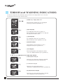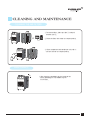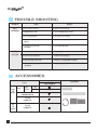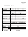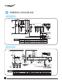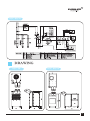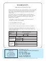
1
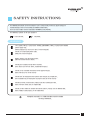
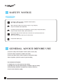
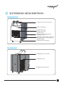
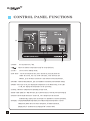
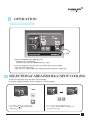
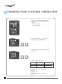
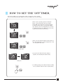
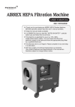
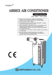
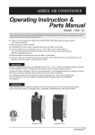
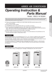
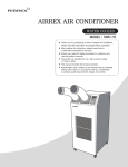
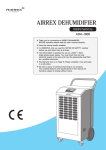
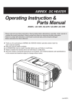
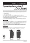
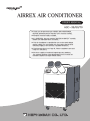
AIRREX AIR CONDITIONER
USER’S MANUAL
HSC-36/60/70
▶ Thank you for purchasing an AIRREX AIR CONDITIONER.
BEFORE operation please read this user’s manual carefully.
▶ Keep this manual readily available.
▶ It is ESSENTIAL that you read the ‘NOTES ON SAFETY’ carefully
before use and follow them at all times.
▶ This Air Conditioner is specified for use on the rated voltage
power supply. For use outside you must check that the local
electricity supply is the same by a qualified electrician.
▶ The Warranty form is on Page 16. Please complete it now and
keep in a safe place.
▶ We have a policy of continual improving to our products.
The contents (features and specifications) in this manual are
therefore subject to change without notice.
TABLE OF CONTENTS
■ SAFETY INSTRUCTIONS
3
■ DESCRIPTION
5
·Front View
5
·Back View
5
·Control Panel
6
■ OPERATING INSTRUCTIONS
2
7
·Running & Stop
·Selection of Area/Room or Spot Cooling
·Temperature Control
·Off Timer
7
·Indicator and Operational Error Alerts
10
7
8
9
■ CLEANING AND MAINTENANCE
11
■ TROUBLE SHOOTING / ACCESSORIES
12
■ SPECIFICATIONS
13
■ WIRING DIAGRAM
14~15
■ DRAWING
15
■ WARRANTY
16
SAFETY INSTRUCTIONS
The following instructions are for ensuring the user’s safety and to prevent any physical injury or
material damage. Please read carefully and follow all instructions.
There are two sections to these instructions: WARNING and CAUTION.
The following symbols are for your guidance:
= You must NOT.
= You MUST.
WARNING
Use a 220V / 60Hz / 1 phase (HSC 36&60), 220V&480V / 60Hz / 3 phase (HSC 60/70)
power supply only.
(Wrong supply may cause a fire and / or shock hazard)
Do not use a damaged power cable.
(Short, fire or shock hazard)
Before cleaning, turn off circuit breaker.
(Otherwise risk of electric shock)
Do not place anything on top of the machine.
(This could cause electric shock, malfunction or injury)
Do not use an extension lead unless of the approved type.
(Risk of fire and / or electric shock)
Do not ‘kink’ or sharply bend the power cable nor put any weight on it.
(The insulation may be damaged causing fire and/ or electric shock)
Do not turn off by circuit breaker. Always turn off at control panel first.
(Risk of electric shock and / or malfunction)
Do not use this cooler on unstable or inclined surfaces. Always use on solid flat floor.
(Risk of falling causing injury, fire or malfunction)
Keep this manual in a visible location near the cooler
for easy reference.
3
SAFETY NOTICE
CAUTION
Do not place cooler on uneven, unstable or inclined surface.
(This could cause malfunction)
When storing the cooler, ensure that it is kept in a dry, cool place.
(To prevent corrosion and malfunction)
If not being used for some time or if lightening is present, always unplug from power.
(To prevent risk of electric shock, short circuit or fire)
Do not spray water on to the cooler nor use solvents such as benzene, thinner or
alcohol for cleaning.
(There is a risk of electric shock and / or short circuit)
Designed for indoor usage.
GENERAL ADVICE BEFORE USE
·Ensure the safety of the location in which cooler is to be used.
·Ensure the floor or ground is smooth and sound.
·Ensure you allow at least 2 feet air space all around the cooler.
·When in position LOCK the casters to prevent rolling.
FOR MAXIMUM EFFICIENCY
·In airtight areas use vertical exhaust into ceiling.
·If possible locate exhaust outlet through a window or door to outside.
·Exhaust ducting should be no longer than maximum efficiency.
·Ensure correct electricity supply.
4
EXTERIOR DESCRIPTION
FRONT VIEW
FLEXIBLE Duct Outlet (COLD AIR)
Digital Controller
Evaporator Filter
AMBIENT AIR INTAKE.
Electric Panel
(ACCESS BY AUTHORISED SERVICE
personnel only)
Condensed water Tank in the case
To collect water and generated
during cooling.
CASTERS (front LOCKABLE)
BACK VIEW
Condenser Outlet (HOT AIR)
Condenser Filter
CONDENSATE WATER OUTLET
5
CONTROL PANEL FUNCTIONS
⑤
⑥
⑦
③
⑧
⑨
④
⑩
②
① Power :
②
:
③ Cool :
①
Use to power On / Off.
Raises or lowers temperature and/ or sleep (off) time.
Use to select cooling mode.
④ Off Timer : To set the length of time, once turned on, that you wish the
cooler to run for. You can set 0~24 hours. Time intervals are
30mins. up to 10 hours and then 1 hour between 10 and 24 hours.
⑤ Remote : From the long distance, you can control the machine by wired remote control.
⑥ Room : If the LED is On, the displayed temperature is for Room temp. If the LED
is Off, the displayed temperature is for spot temp.
⑦ Comp. : When the compressor is operating, the LED is On.
⑧ Error : Error signal ( E1 : High Pressure, E2 : Low Pressure, E3 : Sensor, AF: Eva Freezing)
⑨ Water Full: Red light indicates ‘Tank Full’. The compressor will shut off
automatically. Empty tank and replace in position to resume operation.
⑩ Display : Display Room/Spot temperature, the setting temp and sleep time in case of
setting them. When the user set the sleep timer, ‘hr’ will be turned on.
(Display of 'LO' : under the 32℉, Display of 'HI' : over the 99℉)
6
OPERATION
running & stop
1. START BY PRESSING THE ‘POWER’ BUTTON.
·Cooler will start up automatically.
·To STOP the unit, press the ‘POWER’ button once again.
2. If you wish to operate on fan only, press the ‘COOL’ button. To resume cooling,
press the ‘COOL’ button again.
(Note : There is a 3 minute delay when switching functions to protect the compressor)
SELECTION of AREA/ROOM or SPOT COOLING
To reduce the temperature of the entire room select 'Area/Room'.
For ‘targeted’ cooling of machinery, servers, or people etc. select ‘Spot Cooling’.
1. If you want to display room temperature,
push cool and button simultaneously
during three seconds.
2. If you want to change temperature unit
℉ ↔ ℃, push ▼ and ▲ button simultaneously
during three seconds.
7
TEMPERATURE CONTROL OPERATION
1. When power is ON, the setting temperature is
displayed. Default of setting temperature is
as below.
·50℉ in Spot Mode.
·60℉ in Room Mode.
2. When you push either or button, the
setting temperature is changed.
3. The display showing the set temperature will
blink 3 times.
4. Display range & Setting range.
Mode
Display range
Setting range
Room Temp
32℉~99℉
60℉~86℉
Spot Temp
32℉~99℉
50℉~86℉
Cooling operates when
Room/Spot temperature is more than set
temperature.
Cooling stops when
Room/Spot temperature is less than set
temperature.
8
HOW TO SET THE ‘OFF’TIMER.
This function enables you to set the length of time you want the cooler to operate.
You can set the time period from 30min. to 24 hours in 30min. and 1 hour increments.
1. When cooler is operating, press the ‘Off Timer’
button and set the length of time you want by
pressing ▲ or ▼. Each time you press the button
you will increase the ‘time to off’ period by 30mins.
up to 10 hours, and 1 hour thereafter up to 24 hours.
The display will show .5 for 30min and 1 for an hour.
e.g. One and a half hours will show 1.5.
2. When you have finished setting the time period, the
‘Off Timer’ lamp will be on which indicates the cooler
is in sleep (Off Timer) mode.
off timer lamp is on
3. If you press the ‘Off Timer’ button during its
operation, the remaining time will be shown.
after 1hr
4. To CANCEL timing, press ‘Off Timer’ button for ONE
second. It will then switch the timer off automatically.
9
‘ERROR’and WARNING INDICATORS
The machine’s safety devices will automatically signal any problems via the display window on the control panel.
The information below shows how to read these signals.
1. WATER FULL- Display shows “FU”
When the water container is full, “FU” is displayed
and the LED “Water Full” light will be on.
2. HIGH PRESSURE
‘E1’ is displayed and the ‘Error’ LED will be on
when the pressure of the compressor is too high and
the high pressure switch is open.
3. LOW PRESSURE
‘E2’ is displayed and the ‘Error’ LED will be on
when the pressure of the compressor is too low.
4. SENSOR PROBLEM
If the thermistor is short circuited or cut, ‘E3’ is
displayed and the ‘Error’ LED will be on.
5. ANTI FREEZING When the temperature of the evaporator is below
-2℃, ‘AF’ is displayed and the ‘Error’ LED will be on.
▶ No. 6~8 is applied to the model HSC-60/70
6. COMPRESSOR PROBLEM
When the over current from compressor is detected,
‘E4’ is displayed and the ‘Error’ LED will be On.
7. FAN MOTOR PROBLEM
When the over current from fan motor is
detected, ‘E5’ is displayed and the ‘Error’ LED will be On.
8. BLOWER MOTOR PROBLEM When the over current from blower motor is detected,
‘E6’ is displayed, the ‘Error’ LED will be On.
10
CLEANING AND MAINTENANCE
CLEANING THE AIR FILTERS
1. To remove filters, slide up a little ① and pull
towards you ②.
2. Clean the filters with water or compressed air.
3. Clean evaporator and condenser units with a
vacuum cleaner or compressed air.
MAINTENANCE
1. After cleaning, completely dry the inside of the
unit by operating on ‘Fan Mode’ only for
3 to 4 hours.
11
TROUBLE SHOOTING
TROUBLE
NOT
WORKING
CHECK
REMEDY
● Cord correctly connected
● Connect cord correctly
● POWER button “OFF”
● Press POWER button to “ON”
● Fuse (supply) blown
● Exchange fuse in board
● Breaker on switch board
tripped
● Check load capacity a`nd reset
● Ambient temp. too high
(over 104℉)
● Use only below 104℉
● Filter blocked with dust
● Clean Filter
● Dust in heat exchanger
● Clean heat exchanger
● Obstacle against inlet side
● Remove and allow 20inch clearance
● Ambient temp. too high
(over 104℉) ● Use only below 104℉
POOR
COOLING
ACCESSORIES
MODEL
ITEM
COLD
AIR
OUTLET
DUCT
Diam.
6.9inch.
12
1.6ft.
9.8ft.
DUCT COVER
(FINISHING COLLAR)
FILTER
CASSETTE
HOT
AIR
EXHAUST
HSC-36/60/70
FILTER
CASSETTE
OPTION
DRAWING
SPECIFICATIONS
MODEL
BTU/h
kW
Cooling capacity
Power Supply
HSC36
HSC60
HSC70
36,000
(10.6)
60,000
(17.6)
84,000
(24.6)
220Va.c. 60Hz 1Ph.
220Va.c. 220Va.c. 480Va.c.
60Hz 1Ph. 60Hz 3Ph. 60Hz 3Ph.
480V 60Hz 3Ph.
inch.
29.1 X 33 X55.9
29.1 X 55.1 X 58.7
Ib
396.5
550
Evaporator Air Flow
ft³/min
943
1.940
Power Consumption
kW
4.69
Amp.
21.3
Ib
5.5
Dimensions
Weight
Current Consumption
Refrigerant (R22)
Air Filter
8.2
38
21.5
9.86
9.25
13.8
10.57
Non Fabric filter
Safety Devices
- High Pressure Switch
- Fan motor protection
- Auto ‘Full Tank’ shut off.
Operating Range
- Low pessure switch
- 3 min. delay timer.
- Thermostat for compressor
68°F DB 60% RH~ 104°F DB 40% RH
High Pressure
kgf/cm²/psig
26/370
Low Pressure
kgf/cm²/psig
13/185
Max. Duct Length
Cold Duct
65.6
Hot Duct
32.8
(Either hot or cold, not
both together in use)
11.5
FUSE in power Box
250 Va.c. 5amp
13
WIRING DIAGRAM
HSC 36
HSC 60
14
HSC 60/70
DRAWING
HSC 36
HSC 60/70
15
Warranty
(Applicable to first retail purchaser only)
AIRREX AIR CONDITIONERS give more reliable performance, comfort and durability
the more they are used. They are built under a strict quality assurance regime
which includes inspection both during and after production and exhaustive
reliability testing.
In the unlikely event you have any problems, please contact your dealer or
distributor. If the problem is as a result of a production fault or failure, repairs will
be undertaken free of charge during the period of warranty subject to the
following warranty conditions:
1. If the problem has been caused by customer error or misuse, abuse or
damage, then all repairs will be charged for.
2. This warranty applies to your country.
3. Proof and date of purchase must be supplied.
4. Please complete the details below and keep this warranty in a safe place.
5. All transport charges back to the dealer are at the customers cost. Keep all
original packaging to facilitate return. Return to customer will be at dealers cost
(if genuine warranty claim).
DESCRIPTION
AIRREX AIR CONDITIONER
MODEL
HSC-36/60/70
PRODUCT
SERIAL NO:
DATE OF PURCHASE
Warranty Period
(
) Months
Name of Company
DISTRIBUTOR
Telephone No.
Name :
CUSTOMER
DETAILS
Address :
Telephone :
USA DISTRIBUTOR
AIRREX USA
P.O BOX 340
HEWITT, TEXAS 76643
TEL : 1-800-699-8998
FAX : 1-469-574-7924
[email protected]
HEPHZIBAH CO.,LTD.
423-5 CHUNGCHUN-DONG, BUPYUNG-KU
INCHEON, KOREA
TEL : +82-32-509-5834
FAX : +82-32-502-5519
E-mail : [email protected]
Website : www.airrex.co.kr
● Designs and specifications of products are subject to change without prior notice for the improvement of products.