1
BSR Troubleshooting Guide
Notice
Copyright © 2001
Motorola, Inc.
All rights reserved
No part of this publication my be reproduced in any form or by any means or used to make and any derivative work
(such as translation, transformation or adaptation) without written permission from Motorola, Inc.
Motorola reserves the right to revise this publication and to make changes in content from time to time without
obligation on the part of Motorola to provide notification of such revision or change. Motorola provides this guide
without warranty of any kind, either implied or expressed, including, but not limited to, the implied warranties of
mechantability and fitness for a particular purpose. Motorola may make improvements or changes in the product(s)
described in this manual at any time.
Motorola,the stylized M logo, and Intelligence Everywhere are registered tradmarks of Motorola, Inc. Broadband
Services Router, BSR, BSR 64000, RiverDelta, SmartFlow are trademarks of RiverDelta Networks, Inc. All other
trademarks and registered trademarks are the property of their respective owners.
493183-001
TPD-0023-01 Rev A
Published: March, 2002
Contents
Preface
Scope
ix
Audience
ix
Documentation Set
ix
BSR 1000™ Documentation Set
ix
BSR 1000™ Documentation Set
x
Conventions
xi
Notes, Cautions, Warnings
Contacting Support
1
xii
xiii
Introduction
Introduction
17
Understanding Basic Troubleshooting
Discovering Problems
Viewing Symptoms
Isolating the Problem
Solving the Problem
Evaluating the Solution
2
17
18
19
19
20
20
Checking Physical Equipment
Introduction
23
iii
BSR Troubleshooting Guide
Checking BSR 1000 Power Connections
23
Checking BSR 64000 Power Connections
23
Checking Physical Network Connections
Interpreting BSR 64000 LED Displays
SRM LEDs
24
24
25
Module LEDs
25
Fan Status LEDs
Alarm LEDs
26
27
DOCSIS CMTS Resource Module LEDs
Module LEDs
28
Per-Port LEDs
28
28
OC3/OC12 POS Resource Module LEDs
Module LEDs
29
Per-Port LEDs
30
Interpreting BSR 1000 LED Displays
System LEDs
31
31
Upstream and Downstream Port LEDs
Ethernet Port LEDs
3
32
33
Monitoring SNMP
Introduction
37
Displaying SNMP Information
4
29
37
Troubleshooting the CMTS
Introduction
41
Using Flap Lists to Troubleshoot CM Problems
41
Viewing Flap List Statistics to Identify Network Health
Interpreting Flap List Statistics
Tips for Administrating Flap Lists
44
49
Resolving HFC Network Performance Problems
50
Downstream Signal Reflected on Upstream Path
Slow Performance Detected on Upstream Port
Too Many CPE Hosts on Subscriber CM
Resolving Problems on the Upstream Path
iv
58
57
50
51
41
Contents
Bad Upstream Signal-to-noise Ratio Detected
Upstream Power Level Too Low or High
58
61
Resolving Problems on the Downstream Path
63
Bad Downstream Signal-to-Noise Ratio Detected
Downstream Power Level Too Low or High
Resolving Cable Modem Problems
64
65
67
Misconfigured Authentication String or Key
67
CM Does Not Reply to Station Maintenance Requests
CM is Offline
70
CM Cannot Obtain an IP Address
72
Provisioning Problems Cause CMs Not to Register
CM Does Not Respond to SNMP Messages
5
69
74
77
Troubleshooting TCP/IP
Introduction
81
Resolving Host Connectivity Problems
81
Default Gateway Configuration Problems
81
Misconfigured or Missing Default Routes
82
Incomplete DNS Host Table
DNS Not Running
Handling Routing Problems
Problem Router
83
84
84
84
Misconfigured Router
86
Routing Interface Down
87
Handling a Misconfigured Access List
89
Access List and Filter Misconfigurations
91
Handling UDP Broadcast Forwarding Problems
92
Missing or Misconfigured IP Helper-address Specification
UDP Broadcast Misconfiguration
Resolving PPP Link Over SONET Failures
6
92
93
94
Troubleshooting RIP
Introduction
99
Handling Routing Table Problems
99
v
BSR Troubleshooting Guide
Misconfigured or Missing Network Router Table Entries
Misconfigured Route Filtering
Split Horizon is Disabled
99
100
101
Handling RIP Version Inconsistencies
101
Misconfigured Version of RIP Running on BSR
101
Misconfigured Version of RIP Running on Specified Interface
7
Troubleshooting OSPF
Introduction
109
Handling OSPF-designated Interface Problems
109
Handling Router Neighbor Misconfigurations
Misconfigured Router
110
110
Mismatched OSPF Parameters
111
Mismatched IP MTU
112
Resolving Missing Routes in Routing Table
113
RIP Routing Information Incorrectly Redistributed into OSPF
ABR Configured Without Area 0 Interface
8
119
Handling BGP Routing Problems
119
Missing Neighbor Table Entry
Misconfigured Access List
119
120
Missing Network Destination Advertisement
Handling BGP Peer Misconfigurations
Troubleshooting SONET
Introduction
127
Resolving Fault LED Issues
LOS Determination
LOS Resolution
LOF Determination
LOF Resolution
LOP Determination
vi
115
Troubleshooting BGP
Introduction
9
103
127
127
128
129
129
130
121
121
114
Contents
LOP Resolution
131
Failed POS Module
131
Fail LED Blinks and Lights Repeatedly
Handling Data Loss on SONET Link
Data Loss Determination
Data Loss Resolution
A
131
132
132
134
Cable Modem Registration Process
Introduction
137
Scanning
137
Initial Ranging
138
Establishing IP Connectivity
Establishing Time of Day
TFTP Connectivity
Registration
139
139
139
Baseline Privacy
140
Periodic Ranging
140
Data Exchange
138
141
Index
vii
Preface
Scope
This document describes how to troubleshoot the Motorola™ Broadband Services
Router™ 64000 (BSR 64000™) and Motorola™ Broadband Services Router™ 1000
(BSR 1000™), including hardware, applications, servers, databases, and routing and
SONET-access features. This guide uses the term network to refer to subscriber cable
modems, the BSR family of products, cables and equipment, and host servers.
Audience
This document is for use by those persons who will install and configure the
BSR 64000™ product. Only trained service personnel should install, maintain, or
replace the BSR 64000.
Documentation Set
This document is part of the following documentation sets:
•
•
BSR 1000™ Documentation Set
BSR 1000™ Documentation Set
BSR 1000™ Documentation Set
•
BSR 1000 Command Reference Guide
This document contains the Command Line Interface (CLI) commands for
managing, configuring, and maintaining the BSR 1000.
ix
BSR Troubleshooting Guide
•
BSR 1000 Configuration and Management Guide
This document provides the instructions and procedures for configuring and
managing the BSR 1000.
•
BSR 1000 Installation Guide
This document describes how to install the BSR 1000 product.
•
BSR 1000 Release Notes
These documents provide information about features not described or incorrectly
documented in the main documentation set; known problems and anomalies;
product limitations; and problem resolutions.
•
BSR 1000 SNMP MIB Reference Guide
This document describes the Simple Network Management Protocol (SNMP)
MIBs; provides information that describes standard and proprietary MIB support;
describes how to walk the MIBs and how to compile and load the SNMP MIBs. It
also provides task examples.
BSR 1000™ Documentation Set
•
BSR 64000 Command Reference Guide
This document contains the Command Line Interface (CLI) commands for
managing, configuring, and maintaining the BSR 64000.
•
BSR 64000 Configuration and Management Guide
This document provides the instructions and procedures for configuring and
managing the BSR 64000.
•
BSR 64000 Installation Guide
This document describes how to install the BSR 64000 product.
•
BSR 64000 Release Notes
These documents provide information about features not described or incorrectly
documented in the main documentation set; known problems and anomalies;
product limitations; and problem resolutions.
x
Preface
•
BSR 64000 SNMP MIB Reference Guide
This document describes the Simple Network Management Protocol (SNMP)
MIBs; provides information that describes standard and proprietary MIB support;
describes how to walk the MIBs and how to compile and load the SNMP MIBs. It
also provides task examples.
Conventions
This document uses the conventions in the following table:
Convention
Example
Explanation
angle brackets < >
ping <ip-address>
ping 54.89.145.71
Arguments in italic and enclosed by angle
brackets must be replaced by the text the
argument represents. In the example,
54.89.345.71 replaces <ip-address>. When
entering the argument, do not type the angle
brackets.
bar brackets [ ]
disable [level]
Bar brackets enclose optional arguments. The
example indicates you can use the disable
command with or without specifying a level.
Some commands accept more than one
optional argument. When entering the
argument, do not type the bar brackets.
bold text
cable relay-agent-option
Boldface text must be typed exactly as it
appears.
brace brackets {}
page {on | off}
Brace brackets enclose required text. The
example indicates you must enter either on or
off after page. The system accepts the
command with only one of the parameters.
When entering the text, do not type the brace
brackets.
italic text
boot system <filename>
Italic type indicates variables for which you
supply values in command syntax descriptions.
It also indicates file names, directory names,
document titles, or emphasized text.
xi
BSR Troubleshooting Guide
Convention
Example
Explanation
screen display
Wed May 6 17:01:03
2000
This font indicates system output.
vertical bar |
page {on | off}
A vertical bar separates the choices when a
parameter is required. The example indicates
you can enter either command:
page on or page off
When entering the parameter, do not type the
vertical bar or the brace brackets.
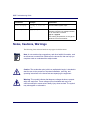
Notes, Cautions, Warnings
The following icons and associated text may appear in this document.
Note: A note contains tips, suggestions, and other helpful information, such
as references to material not contained in the document, that can help you
complete a task or understand the subject matter.
Caution: The exclamation point, within an equilateral triangle, is intended to
alert the user to the presence of important installation, servicing, and
operating instructions in the documents accompanying the equipment.
Warning: This symbol indicates that dagerous voltages levels are present
within the equipment. These voltages are not insulated and may be of
sufficient strength to cause serious bodily injury when touched. The symbol
may also appear on schematics.
xii
Preface
Contacting Support
Use the following information to contact Support:
U.S.
1-888-944-HELP
1-888-944-4357
International
+.215-323-0044
WWW
http://www.gi.com/BUSAREA/CUSACC/websupport.html
Email
[email protected]
xiii
1
Introduction
Introduction
Introduction
This chapter identifies the basic tasks you perform to solve problems with the network
and hardware and software configurations.
The next sections describe how to perform standard troubleshooting techniques:
•
•
•
•
•
•
Understanding Basic Troubleshooting
Discovering Problems
Viewing Symptoms
Isolating the Problem
Solving the Problem
Evaluating the Solution
Understanding Basic Troubleshooting
The basic steps you need to perform to troubleshoot network problems are as follows:
1. Identify the cause or symptom of the problem, which can be any undesired result
or behavior. See Discovering Problems, later, to learn how to identify problems.
Note: One or more symptoms or causes can be related to a single problem.
2. Isolate the cause or symptom of the problem and try to determine its scope. For
example, determine if it is the whole HFC network, a particular subnetwork on
the HFC network, or just one subscriber that is experiencing the problem. See
Isolating the Problem, later in this document, for more information.
3. Once the cause or symptom of a problem is isolated, make a list of
troubleshooting procedures that you plan to use. Refer to subsequent chapters in
this document for specific troubleshooting procedures you can use.
1-17
BSR Troubleshooting Guide
4. Document the changes and effects of changes as you perform troubleshooting
procedures, and note any new troubleshooting procedures that you use. This
simple precaution helps to avoid repeating steps, allows for future reference in
case the problem reoccurs, and is especially useful for troubleshooting
intermittent problems.
5. Determine if the problem is solved. Ensure that the troubleshooting procedure did
not cause new problems.
6. If the problem is not solved, try to identify problem causes more clearly, isolate
any additional causes, and perform additional troubleshooting procedures to
correct the problem.
Discovering Problems
Ensure that you thoroughly understand the network so that you can establish a
baseline from which to work, and distinguish the differences between normal and
abnormal activity on the network.
Perform the following steps to determine the source of problems:
1-18
•
Review release notes and technical bulletins to determine if there are any
incompatibilities or known problems.
•
Gather information for all the possible causes or symptoms to more quickly
isolate the problem.
•
•
•
Discover if the problem relates to another problem that you must solve first.
•
Identify aspects that causes or symptoms have in common to determine if they are
related.
•
Look for network patterns in the causes. What time of day did these problems
occur? What events were logged? What network thresholds were transgressed?
•
Record any changes that occurred since the network was last functioning
correctly. Changes in network activity may relate to a configuration change.
Record all configuration parameters that relate to the problem.
Determine if the network configuration has changed recently, such as the addition
or removal of components, upgrading, or reconfiguration.
Introduction
•
Record any changes that occurred since the last time the BSR was operating
properly. Investigate any configuration changes that might be related to the
problem.
Viewing Symptoms
Perform the following tasks to view and compare symptoms that are related to a
problem:
•
Repeat the conditions that led to the symptom. Consider any errors or failures that
can cause a particular symptom, and test them to see if they are causing the
symptom.
•
Determine if any symptoms are related. Are there unexpected or undesired results
in more than one area? If so, find the areas in common and the variables that
affect them. The source of the problem is often found in similar areas.
•
Focus on one symptom or a set of related symptoms of a problem. However, do
not completely disregard other symptoms, because what may appear to be an
unrelated problem may actually be related based on other symptoms.
Isolating the Problem
A problem can have one or more causes. To identify the cause of unwanted behavior,
use the following techniques:
•
Isolate the problem. For example, isolate a problem to one part of the network or
to a specific access module.
•
•
Find the functions that are working correctly.
•
Determine if there have been any additions, changes, or upgrades to the network.
If so, consider any consequences the changes could have had on the network, and
whether they affect the current situation.
Retrace the steps that were taken, and return the network to its condition before
the problem first appeared. Once the network is in a known condition, take
incremental steps and observe the network to learn when and where the problems
occur.
1-19
BSR Troubleshooting Guide
Solving the Problem
Different problems require different actions and solutions, but follow these basic steps
to fix any problem:
1. Identify the course of action and the steps you plan to take.
2. Decide what tools are necessary to fix the problem on the network. For example,
you can use the CLI as a tool to look at events and set SNMP traps. You can use a
cable tester to check physical media connections.
3. Perform each step for the course of action.
4. Verify the result of each action using the available CLI show commands. For
example, if you enabled a port, use the appropriate show ip interface brief
command in Privileged EXEC mode to verify that the port is enabled.
5. If more than one possible action exists, select the easiest one first to quickly
eliminate possibilities, or select the action that appears most likely to solve the
problem first, even if it is the most time-consuming or difficult to perform.
Evaluating the Solution
Once you find the solution, test it to ensure that no new symptoms or problems occur.
If new symptoms or problems do occur, repeat the troubleshooting process to
determine the cause. If problems or symptoms recur, create a standard test plan to
evaluate fixes.
1-20
2
Checking Physical
Equipment
Checking Physical Equipment
Introduction
This chapter discusses how to check physical connections and observe LEDs on
the BSR products. You should check power and network connections anytime you
install new hardware, or whenever a problem occurs.
The next sections describe how to check physical problems on the BSR:
•
•
•
•
Checking BSR 1000 Power Connections
Checking BSR 64000 Power Connections
Checking Physical Network Connections
Interpreting BSR 64000 LED Displays
Checking BSR 1000 Power Connections
Inspect any uninterruptible power supplies (UPS) connected to the BSR 1000.
Sometimes the UPSs can fail.
Checking BSR 64000 Power Connections
Inspect the power LEDs labeled A and B on the front of the Supervisory Routing
Module (SRM). If power source A or B failed, the corresponding LED displays a
failed condition. If the two -48V DC power filter modules A and B on the rear of
the unit are operational, check the -48V DC (40-60 V DC input) power source.
The power source could either be an AC-to-DC power converter, or a battery
connection attached to a charger. Make sure the power converter or charger is
operating properly.
2-23
BSR Troubleshooting Guide
Checking Physical Network Connections
Check network connections for loose, broken, or disconnected cables. Inspect the
cable terminating connectors for damage.
Use the following techniques to troubleshoot physical cables on the network:
•
•
•
Use the CLI show commands to view port and slot information.
•
Use cable testing equipment to measure or ensure that the correct distances for
cable runs are in place.
•
If the BSR 64000 is installed, ensure that all modules are seated correctly in
the chassis.
•
Replace any suspected defective modules or devices with known working
spare modules or devices.
•
Refer to the system documentation or service contract information for
replacements and on-site spares.
Use a cable tester to test the network cables for damage.
Verify that all the networks associated with the BSR are within proper
specifications.
Interpreting BSR 64000 LED Displays
The BSR 64000 provides three types of LEDs that indicate its operational status:
•
•
•
SRM LEDs
DOCSIS CMTS Resource Module LEDs
OC3/OC12 POS Resource Module LEDs
Observing LED displays on the BSR 64000 is the quickest way to diagnose
possible power, network connectivity, and network traffic problems. The LEDs on
the BSR can indicate problems from the fuse alarm panel in the cable headend
offices to the port level. For example, if a problem occurs, use the following steps
to determine the problem:
1. View the LEDs on the fuse alarm panel on the rack to determine which BSR
has a detected fault.
2-24
Checking Physical Equipment
2. Observe the LEDs on the SRM on the BSR 64000 or the front panel of the
BSR 1000 to determine if there is a fail condition or alarm.
•
If there is a fail condition and the SRM circuitry is not receiving power,
replace the SRM on the BSR 64000.
•
If there is an alarm condition, check the modules on the BSR 64000 to
determine which one is faulty.
•
If there is a fail condition on a BSR 1000, replace it.
•
If there is an alarm condition on a BSR 1000, troubleshoot the faulty port.
3. Observe the LEDs on the faulty module of the BSR 64000 to determine if
there is a fail condition or alarm.
•
If there is a fail condition and the module’s circuitry is not receiving
power, replace the module.
•
If there is an alarm condition, check the port interfaces to determine which
ones are faulty. The solution may require that you swap the module with a
new one, or troubleshoot the faulty port.
SRM LEDs
The SRM has the following groups of LEDs that indicate its operational status and
the status of other chassis components. The subsections that follow describe the
display states of these LED groups:
•
•
•
Module LEDs
Fan Status LEDs
Alarm LEDs
Module LEDs
The DOCSIS CMTS Module LEDs are visible on the module front panel and are
labeled: Fail, Status, and Alarm.
2-25
BSR Troubleshooting Guide
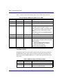
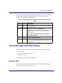
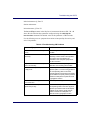
Table 2-1 describes the possible display states of these LEDs during operation.
Table 2-1 Module LED Display States for the SRM
Fail
Status
Alarm
Interpretation
Off
Green
Off
Normal operating status.
Off
Green
Red
Failure. SRM is operating with an alarm
condition.
Red
Off
Off
Indicates a module hardware failure.
The LED is red when the BSR is receiving
power, but there is no power to the circuitry. This
can occur if a fuse on a BSR 64000 module is
down.
A red LED can also occur if the BSR 64000 does
not boot correctly.
Red
Off
Red
Failure. SRM is not operational.
Red
Green
Red
Reset. SRM is booting.
Off
Off
Off
If the Status LED is off and the Fail LED is off,
there is no power. The power source for the BSR
64000 has failed.
•
Check the -48V DC power source(s) for
power to the BSR 64000. The -48V DC
power source may be faulty.
Check the UPS for the BSR 1000.
Fan Status LEDs
The SRM provides a set of Fan Status LEDs for each of the fan arrays installed in
the BSR 64000 chassis. These LEDs are visible on the module front panel of the
SRM and are labeled: OK and Fail. Table 2-2 describes the possible display states
of the LEDs.
Table 2-2 SRM Fan Status LED Display States
2-26
OK
Fail
Interpretation
Green
Off
Normal operating status.
Off
Red
Failure. One or more fans of the fan module
failed or fan module is removed.
Checking Physical Equipment
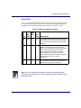
Alarm LEDs
Table 2-3 describes the BSR 64000 Alarm LEDs on the SRM. The SRM provides
a set of three Alarm LEDs. These LEDs are visible on the module front panel of
the SRM and are labeled: MIN (Minor), MAJ (Major), and CRIT (Critical).
Table 2-3 SRM Alarm LED Display States
MIN
LED State
MAJ
Stat CRIT
e
State Interpretation
MIN
Yellow
Off
Off
Minor alarms indicate problems that do not have a
serious effect on service to customers or problems
in circuits that are not essential to network element
operation.
MAJ
Off
Red
Off
Major alarms are used for hardware or software
conditions that indicate a serious disruption of
service or the malfunctioning or failure of important
circuits. These conditions require immediate
attention and response to restore or maintain
system capability. The urgency is less than in
critical situations because of a lesser immediate or
impending effect on service or system
performance.
CRIT
Off
Off
Red
Critical alarms are used to indicate that a severe
service-affecting condition has occurred and that
immediate corrective action is imperative.
Note: When an audible alarm condition sounds, press the ACO button
located on the front panel of the System Resource Module (SRM) to clear
the audible alarm.
2-27
BSR Troubleshooting Guide
DOCSIS CMTS Resource Module LEDs
The DOCSIS CMTS Module has two groups of LEDs that indicate its operational
status:
•
•
Module LEDs
Per-Port LEDs
The following subsections describe the possible display states of these LED types.
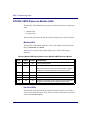
Module LEDs
The DOCSIS CMTS Module LEDs are visible on the module front panel and are
labeled: Fail, Status, and Alarm.
Table Table 2-4 describes the possible display states of these LEDs during
operation.
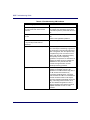
Table 2-4 Module LED Display States for the DOCSIS CMTS Resource Module
Fail
Status
Alarm
Interpretation
Off
Green
Off
Normal operating status.
Off
Green
Red
Failure. Module is operating with an alarm condition.
Note: This sequence of LED occurs when an alarm condition
is detected on individual upstream and downstream ports.
Red
Off
Off
Indicates a module hardware failure.
Red
Off
Red
Failure. Module is not operational.
Red
Green
Red
Reset. Module is booting.
Off
Off
Off
Module is not receiving power or is not secured in the chassis
though its module ejectors and integrated ejector switch.
Per-Port LEDs
The DOCSIS CMTS downstream port and each upstream port have two LEDs to
indicate their operational status. These LEDs are visible on the module front panel
and are labeled Link and Fail.
2-28
Checking Physical Equipment
Port LEDs are grouped vertically. A number to the right each LED group indicates
the channel number associated with the group. The single downstream channel is
numbered 0 and the four upstream channels are numbered 0, 1, 2, 3. Table 2-5
describes the possible display states of these LEDs during operation.
Table 2-5 BSR 64000 Downstream and Upstream Port LED Display States
Link
Fail
Interpretation
Green
Off
Normal operating status.
Green
Red
Operating with an alarm condition detected.
Note: An alarm condition detected for an individual port
also causes the System Alarm LED to light.
Off
Red
Failed port. Port is not operational.
Off
Off
Port is not configured.
Note: Check module LEDs to determine if the module is
receiving power.
OC3/OC12 POS Resource Module LEDs
The OC3/OC12 POS Resource Module has two groups of LEDs that indicate its
operational status:
•
•
Module LEDs
Per-Port LEDs
The following subsections describe the possible display states of these LED types.
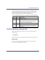
Module LEDs
The OC3/OC12 POS Resource Module LEDs are visible on the module front
panel and are labeled: Fail, Status, and Alarm.
2-29
BSR Troubleshooting Guide
Table Table 2-4 describes the possible display states of these LEDs during
operation.
Table 2-6 Module LED Display States for the OC3/OC12 POS Resource Module
Fail
Status
Alarm
Interpretation
Off
Green
Off
Normal operating status.
Off
Green
Red
Failure. Module is operating with an alarm condition.
Note: This sequence of LED occurs when an alarm condition
is detected on individual upstream and downstream ports.
Red
Off
Off
Indicates a module hardware failure.
Red
Off
Red
Failure. Module is not operational.
Red
Green
Red
Reset. Module is booting.
Off
Off
Off
Module is not receiving power or is not secured in the chassis
though its module ejectors and integrated ejector switch.
Per-Port LEDs
The OC3/OC12 POS Resource Module supports four SONET ports and two 10/
100BaseT Ethernet ports. Each SONET and Ethernet port on the OC3/OC12 POS
Resource Module has two LEDs associated with it to indicate the port’s
operational status. These LEDs are visible on the module front panel and are
labeled Link and Fail.
2-30
Checking Physical Equipment
Port LEDs are grouped vertically. A number to the right each LED group indicates
the port number associated with the group. Table 2-5 describes the possible
display states of these LEDs during operation.
Table 2-7 BSR 64000 OC3/OC12 POS Port and Ethernet LED Display
States
Link
Fail
Interpretation
Green
Off
The SONET or Ethernet port is operational and is receiving
and transmitting data.
Green
Red
Operating with an alarm condition detected.
The SONET port is not operational because there is a loss
of signal (LOS), loss of frame (LOF), or loss of pointer
(LOP) condition.
Note: An alarm condition detected for an individual port
also causes the System Alarm LED to light on the System
Resource Module (SRM).
Off
Red
Failed port. Port is not operational.
Off
Off
Port is not configured or is disabled.
Note: Check module LEDs to determine if the module is
receiving power.
Interpreting BSR 1000 LED Displays
The BSR 1000 provides three types of LEDs that indicate its operational status:
•
•
•
System LEDs
Upstream and Downstream Port LEDs
Ethernet Port LEDs
The following sections describe the LED types.
System LEDs
The BSR 1000 system LEDs are located on the left side of the BSR 1000 front
panel and are labeled Fail, Status, and Alarm.
2-31
BSR Troubleshooting Guide
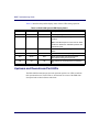
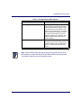
Table 2-8 describes the possible display states of these LEDs during operation.
Table 2-8 BSR 1000 System LED Display States
Fail
Status
Alarm
Interpretation
Off
Green
Off
Normal operating status.
Off
Green
Red
Failure. BSR 1000 is operating with an alarm
condition.
Note: This LED sequence occurs when an alarm
condition is detected on individual upstream and
downstream ports.
Red
Off
Off
Fuse failure possibly indicating a hardware
failure.
Red
Off
Red
Failure. BSR 1000 is not operating.
Red
Green
Red
Reset. Reset button was pressed and the
BSR 1000 is starting its boot process.
Off
Off
Off
BSR 1000 is not receiving power or is switched
Off.
Upstream and Downstream Port LEDs
The BSR 1000 downstream port and each upstream port has two LEDs to indicate
their operational status. These LEDs are located near the center of the BSR 1000
front panel and are labeled Status and Alarm.
2-32
Checking Physical Equipment
Port LEDs are grouped vertically. A number above each LED group indicates the
channel number associated with the group. The single downstream channel is
numbered 0 and the four upstream channels are numbered 0, 1, 2, 3. Table 2-5
describes the possible display states of these LEDs during operation.
Table 2-9 BSR 1000 Downstream and Upstream Port LED Display States
Status
Alarm
Interpretation
Green
Off
Normal operating status. The downstream
port is operational and is transmitting data to
the cable modem (CM) network.
Green
Red
Operating with an alarm condition detected.
Note: An alarm condition detected for an
individual port also causes the System Alarm
LED to light.
Off
Red
Failed port. Port is not operational.
Off
Off
Port is not configured.
Ethernet Port LEDs
The Ethernet port at the back of the BSR 1000 has two associated LEDs located to
the right of the port. Table 2-10 provides an interpretation of the LED displays
Table 2-10 BSR 1000 Ethernet Port LED Display States
LED Label
10/100BASE-T
Link
Display State Interpretation
On indicates that the port is operating at 100 Mbps.
Off indicates that the port is operating at 10 Mbps.
On indicates a working Ethernet connection between the
BSR 1000 and the device at the other end of the physical
connection.
Off indicates that a connection to the device at the other end of
the physical connection is not established.
2-33
3
Monitoring SNMP
Monitoring SNMP
Introduction
This chapter describes how to use Simple Network Management Protocol (SNMP)
information to monitor BSR system management networking activity.
Displaying SNMP Information
SNMP information lets you monitor management activities on the network. For
example, SNMP traps are error messages sent from the SNMP agent to the SNMP
manager to alert system administrators about Cable Modems (CMs) going offline or
online.
Follow the CLI show command to access SNMP Information:
RDN#show snmp
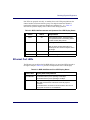
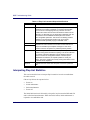
Table 3-1 describes the output of the SNMP show command:
Table 3-1 Understanding SNMP show Information
SNMP Information
Explanation
Status
Displays the status of SNMP as either stopped or enabled.
Port Number
Identifies the port number that the SNMP agent uses to
listen for SNMP information. You must know which SNMP
port is used when configuring servers for the BSR.
Contact
Identifies the network administrator responsible for
configuring the BSR.
Description
Provides the hardware version, vendor name, and Boot
Rom version.
Location
Identifies the BSR location.
SNMP In Packets
Incoming SNMP Packets.
•
Bad SNMP version
errors
SNMP version is incompatible with the SNMP in use.
•
Unknown community
names
Displays the total number of SNMP messages received
that used an unknown SNMP community name.
3-37
BSR Troubleshooting Guide
Table 3-1 Understanding SNMP show Information
SNMP Information
Explanation
•
Illegal operations for
community names
supplied
Displays command operations that are not allowed for the
existing community names.
•
ASN parse errors
Displays the total number of Abstract Syntax Notation
(ASN) errors found in SNMP messages received.
•
Requested variables
Shows the requested SNMP variables.
•
Changed variables
Shows the changed SNMP variables.
•
Get requests
Identifies the number of times that a MIB variable or object
is selected.
•
Get-next requests
Identifies the number of times the next MIB variable or
object is selected.
•
Set requests
Identifies the number of times that a MIB variable or object
is set.
SNMP Out Packets
Outgoing SNMP Packets.
•
Packets too big
Displays the total number of SNMP Protocol Data Units
(PDUs) sent that contained an error-status field value of
tooBig.
•
No such name errors
Displays the total number of SNMP PDUs sent that
contained an error-status field value of nosuchName.
•
Bad values
Displays the total number of SNMP PDUs sent that
contained an error-status field value of badValue.
•
General errors
Displays the total number of SNMP PDUs sent that
contained an error-status field value of genErr.
•
Responses
Displays the total number of SNMP Get-Response PDUs
sent and processed.
•
Traps
Displays the total number of SNMP Trap PDUs received
and processed. SNMP traps provide information about the
following:
•
Potentially harmful network environment conditions
•
Processor status
•
Port status
•
Security issues
The BSR generates SNMP traps based on the supported
IOS features.
3-38
4
Troubleshooting the CMTS
Troubleshooting the CMTS
Introduction
This chapter provides troubleshooting solutions to some common Data Over Cable
Service Interface Specifications (DOCSIS) network problems with the following:
•
•
•
•
•
Using Flap Lists to Troubleshoot CM Problems
Resolving HFC Network Performance Problems
Resolving Problems on the Upstream Path
Resolving Problems on the Downstream Path
Resolving Cable Modem Problems
Using Flap Lists to Troubleshoot CM Problems
The BSR maintains a database of flapping CMs to assist in locating cable plant
problems. The flap list feature tracks the upstream and downstream performance
of all CMs on the network, without impacting throughput and performance
between the CM and BSR, or creating additional packet overhead on the HFC
network.
Refer to the BSR 64000 Configuration and Management Guide for more
information on configuring flap-list settings.
Viewing Flap List Statistics to Identify Network Health
Flap lists are used to collect statistics for determining CM problems on the
network. There are several different options for sorting flap list statistics. The CM
flap list keeps track of the CM MAC address, up and down transitions, registration
events, missed periodic ranging packets, upstream power adjustments on the BSR.
This section describes the different sorting options and describes the command
output fields.
CMs appear in the flap list when any of the following conditions are detected:
•
•
The CM re-registers more frequently than the configured insertion time.
Intermittent keepalive messages are detected between the BSR and the CM.
4-41
BSR Troubleshooting Guide
•
The CM upstream transmit power changes beyond the configured power
adjust threshold.
Follow these steps to view flap list statistics by using different sorting options:
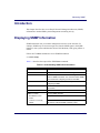
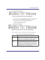
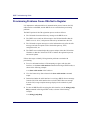
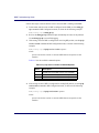
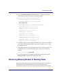
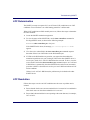
1. To view all flap list statistics for CMs, use the show cable flap list command
in Privileged EXEC mode as shown in the following example:
RDN#show cable flap-list
The following output displays:
Figure 4-1 show cable flap-list Command Output
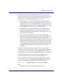
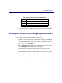
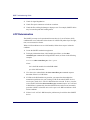
2. To sort the flap list statistics by the CM flap, use the show cable flap-list
sort-flap command in Privileged EXEC mode as shown in the following
example:
RDN#show cable flap-list sort-flap
The following output displays:
Figure 4-2 show cable flap-list sort-flap Command Output
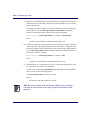
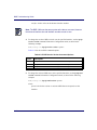
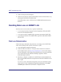
3. To sort the flap list statistics by the time at which the CM flap occured, use the
show cable flap-list sort-time command in Privileged EXEC mode as shown
in the following example:
RDN#show cable flap-list sort-time
4-42
Troubleshooting the CMTS
The following output displays:
Figure 4-3 show cable flap-list sort-time Command Output
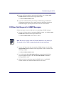
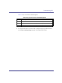
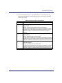
4. To sort the flap list statistics by the cable upstream interface on which the CM
flap occured, use the show cable flap-list sort-interface command in
Privileged EXEC mode as shown in the following example:
RDN#show cable flap-list sort-interface
The following output displays:
Figure 4-4 show cable flap-list sort-interface Command Output
Table 4-1 identifies the flap list command output column field identifications:
Table 4-1 Flap List Command Output Identifications
Field
Identification
MAC ID
Lists the MAC addresses of the CMs sorted by the flap rate or most
recent flap time. The first six digits in the CM MAC address indicate
the vendor ID of the CM manufacturer, followed by six digits
indicating a unique host address. Each CM MAC address is unique.
Cable IF
Detects the cable interface up/down flap. This is the cable interface
on the BSR 64000 DOCSIS module or BSR 1000. It denotes the
DOCSIS module slot number (BSR 64000), the downstream and
the upstream port number. The flap list data can be sorted based
on the upstream port number which is useful when isolating reverse
path problems unique to certain combining groups.
4-43
BSR Troubleshooting Guide
Table 4-1 Flap List Command Output Identifications
Field
Identification
Ins
The Insertions Link process is used by a CM to perform an initial
maintenance procedure to establish a connection with the BSR.
The Ins column is the flapping CM’s (re) insertion count and
indicates the number of times the a CM starts and inserts into the
network in an abnormal way. An abnormality is detected when the
time between link re-establishment attempts is less than the
user-configurable parameter. This function can identify potential
problems in the downstream interface such as incorrectly
provisioned CMs repeatedly trying to reestablish a link.
Hit
The Hit and Miss column fields detect the intermittent upstream; the
keepalive hits versus misses is the number of times CMs do not
respond to the MAC layer keepalive messages. If there are a
number of misses, this points to a potential upstream problem.
Miss
P-Adj
The Power Adjustment column field shows power adjustment
statistics during station maintenance polling. This column indicates
the number of times the BSR tells a CM to adjust the transmit
power more than the configured threshold. If constant power
adjustments are detected, an amplifier problem is usually the
cause. The source of failure is found by viewing CMs either in front
or behind various amplifiers.
Flap Time
Indicates the most recent time a flap has occured for a particular
CM.
Interpreting Flap List Statistics
This section describes how to interpret flap list statistics in order to troubleshoot
the cable network
CM activity follows the sequence below.
•
•
•
•
Power-on
Initial maintenance
Station maintenance
Power-off
The initial link insertion is followed by a keepalive loop between the BSR and CM
and is called station maintenance. When the link is broken, initial maintenance is
repeated to re-establish the link.
4-44
Troubleshooting the CMTS
Initial maintenance @ Time T1
Station maintenance
Init maintenance @ Time T2
The Ins and Flap counters in the flap list are incremented whenever T2 – T1 < N
where N is the insertion-time parameter configured using the cable flap-list
insertion-time command. The default value for this parameter is TBD seconds.
Use the following cause or symptom observations to interpret flap list activity and
solve CM problems:
Table 4-2 Troubleshooting CM Problems
Cause or Symptom
Problem
Subscriber CM shows a lot of flap list
activity
CM is having communication problems with
the BSR.
Subscriber CM shows little or no flap
list activity.
The CM is communicating with the BSR
effectively, however there is still a problem.
The problem can be isolated to the
subscriber’s CPE computer equipment or
the CM connection.
Ten percent of the CMs in the flap list
show a lot of activity.
These CMs are most likely having
difficulties communicating with the BSR.
CMs have a lot of power adjustment
(P-Adj) errors.
CMs have problems with their physical
upstream paths or in-home wiring problems.
Use corresponding CMs on the same
physical upstream port interface with similar
flap list statistics to quickly resolve problems
outside the cable plant to a particular node
or geographic location.
All CMs are incrementing the insertion
at the same time.
There is a provisioning server failure.
A CM has more than 50 power
adjustments per day.
The CM has a suspect upstream path.
Corresponding CMs on the same physical
upstream port interface with similar flap list
statistics can be used to quickly resolve
problems outside the cable plant to a
particular node or geographic location.
4-45
BSR Troubleshooting Guide
Table 4-2 Troubleshooting CM Problems
4-46
Cause or Symptom
Problem
A CM has roughly the same number of
hits and misses and contain a lot of
insertions.
There is a problematic downstream path.
For example, the downstream power level
to the CM may have a power level that is too
low.
A high flap list insertion (Ins) time
number.
Intermittent downstream synchronization
loss.
DHCP or CM registration problems.
Low miss/hit ratio, low insertion, low
P-adj, low flap counter and old
timestamp.
Indicates an optimal network situation.
High ratio of misses over hits (> 10%)
Hit/miss analysis should be done after the
"Ins" count stops incrementing. In general, if
the hit and miss counts are about the same
order of magnitude, then the upstream may
be experiencing noise. If the miss count is
greater, then the CM is probably dropping
out frequently and not completing
registration. The upstream or downstream is
perhaps not stable enough for reliable link
establishment. Very low hits and miss
counters and high insertion counters
indicate provisioning problems.
High power adjustment counter.
Indicates the power adjustment threshold is
probably set at default value of 2 dB
adjustment. The CM transmitter step size is
1.5 dB, whereas the headend may
command 0.25 dB step sizes. Tuning the
power threshold to 6 dB is recommended to
decrease irrelevant entries in the flap list.
The power adjustment threshold may be set
using <cable flap power threshold <0-10
dB> from Global Configuration mode. A
properly operating HFC network with short
amplifier cascades can use a 2-3 dB
threshold.
Troubleshooting the CMTS
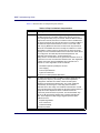
Table 4-2 Troubleshooting CM Problems
Cause or Symptom
Problem
High P-Adj (power adjustment)
This condition can indicate that the fiber
node is clipping the upstream return laser.
Evaluate the CMs with the highest number
of correcteds and uncorrecteds first. If the
CMs are not going offline (Ins = 0), this will
not be noticed by the subscriber. However,
they could receive slower service due to
dropped IP packets in the upstream. This
condition will also result in input errors on
the cable interface.
High insertion rate.
If link re-establishment happens too
frequently, then the CM is usually having a
registration problem.This is indicated by a
high ‘Ins’ counter which tracks the ‘Flap’
counter.
Note: CMs go offline faster than the frequency hop period and can cause
the frequency to stay fixed while CMs go offline. Reduce the hop period to
10 seconds to adjust to the hop frequency period.
4-47
BSR Troubleshooting Guide
Table 4-3 describes how to interpret flap list statistics:
Table 4-3 Flap List Statistic Interpretations
Field
Description
Hit and Miss
The HIT and MISS columns are keepalive polling statistics between
the BSR and the CM. The station maintenance process occurs for
every CM approximately every 10 seconds. When the BSR receives a
response from the CM, the event is counted as a Hit. If the BSR does
not receive a response from the CM, the event is counted as a Miss. A
CM will fail to respond either because of noise or if it is down. CMs
which only log Misses and zero Hits are assumed to be powered off.
Misses are not desirable since this is usually an indication of a return
path problem; however, having a small number of misses is normal.
The flap count is incremented if there are M consecutive misses where
M is configured in the cable flap miss-threshold parameter. The
parameter value ranges from 1-12 with a default of 6.
Ideally, the HIT count should be much greater than the Miss counts. If
a CM has a HIT count much less than its MISS count, then registration
is failing. Noisy links cause the MISS/HIT ratio to deviate from a
nominal 1% or less. High Miss counts can indicate:
•
Intermittent upstream possibly due to noise
•
Laser clipping
•
Common-path distortion
•
Ingress or interference
Too much or too little upstream attenuation
P-Adj
The station maintenance poll in the BSR constantly adjusts the CM
transmit power, frequency, and timing. The Power Adjustments
(P-Adj)column indicates the number of times the CM’s power
adjustment exceeded the threshold value. The power adjustment
threshold may be set using the <cable flap power threshold >
parameter with a value range of 0-10 dB and a default value of 2 dB.
Tuning this threshold is recommended to decrease irrelevant entries in
the flap list. Power Adjustment values of 2 dB and below will
continuously increment the P-Adj counter. The CM transmitter step
size is 1.5 dB, whereas the headend may command 0.25 dB step
sizes. Power adjustment flap strongly suggests upstream plant
problems such as:
•
Amplifier degradation
•
Poor connections
•
Thermal sensitivity
Attenuation problem
4-48
Troubleshooting the CMTS
Table 4-3 Flap List Statistic Interpretations
Field
Description
Flap
The Flap counter indicates the number of times the CM has flapped.
This counter is incremented when one of the following events is
detected:
Unusual CM insertion or re-registration attempts. The Flap and the Ins
counters are incremented when the CM tries to re-establish the RF link
with the BSR within a period of time that is less than the
user-configurable insertion interval value.
Abnormal Miss/Hit ratio The Flap counter is incremented when N
consecutive Misses are detected after a Hit where N can be
user-configurable with a default value of 6.
Unusual power adjustment The Flap and P-adj counters are
incremented when the CM’s upstream power is adjusted beyond a
user-configurable power level.
Time
Time is the timestamp indicating the last time the CM flapped. The
value is based on the clock configured on the local BSR. If no time is
configured, this value is based on the current uptime of the BSR. When
a CM meets one of the three flap list criteria, the Flap counter is
incremented and Time is set to the current time.
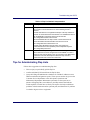
Tips for Administrating Flap Lists
Follow these suggestions for administrating flap lists:
•
•
•
Write script(s) to periodically poll the flap list.
Analize and identify CM trends from the flap list data.
Query the billing and administrative database for CM MAC address-to-street
address translation and generate reports. These reports can then be given to the
Customer Service Department or the cable plant’s Operations and
Maintenance Department. Maintenance personnel use the reports to see
patterns of flapping CMs, street addresses, and flap statistics that indicate
which amplifier or feeder lines are faulty. The reports also help troubleshoot
problems in the downstream and/or upstream path, and determine if a problem
is related to ingress noise or equipment.
4-49
BSR Troubleshooting Guide
•
Save the flap list statistics to a database server at least once a day to keep a
record of flap list statistics which includes upstream performance and quality
control data. These statistics can be used again at a later time to evaluate
trends and solve intermittant problems on the HFC networks. Once the flap list
statistics are backed up daily on the database server, the flap list statistics can
be cleared.
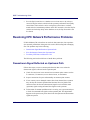
Resolving HFC Network Performance Problems
If Cable Modem (CM) subscribers can use their data connection, but experience
slow network performance during activities such as Web surfing and exchanging
files. The problem may be the following:
•
•
•
Downstream Signal Reflected on Upstream Path
Slow Performance Detected on Upstream Port
Too Many CPE Hosts on Subscriber CM
The following sections describe how to handle these problems.
Downstream Signal Reflected on Upstream Path
Follow these steps to correct common path distortion that occurs when the
downstream signal is reflected on the upstream path:
1. Check for corrosion or loose connections on common point contacts such as
F-connectors, G-connectors, screw-down seizures, or terminators.
2. Inspect connections for poor craftsmanship on common point contacts.
3. If one or more poor or damaged contacts have been detected, these contacts
may develop an electronic potential that functions like a tiny diode. This
situation causes the forward (downstream) signals to mix with the return
(upstream) signal causing unwanted beat signals on the spectrum.
4. To determine if common path distortion is occuring, use a spectrum analyser
to check for unwanted beat signals on the upstream path. This impairment
happens on the spectrum at points where both the upstream and downstream
signals are present.
4-50
Troubleshooting the CMTS
5. Do the following tasks to repair damaged contacts:
•
Ensure that contacts are made of similar metals.
•
Ensure that contacts are clean.
•
Ensure that contacts are securely fastened.
•
Replace or repair defective equipment, if necessary.
Slow Performance Detected on Upstream Port
Subscriber CMs connected to an upstream port are experiencing poor or slow
performance.
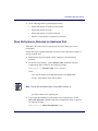
Follow these steps to gather information and correct slow performance related to a
specific upstream port:
1. Determine the physical location or MAC addresses of the CMs having
problems.
2. To enter the cable interface, use the interface cable command, in Global
Configuration mode as shown in the following example:
RDN(config-if)#interface cable <slot>/<interface>
where:
slot is the slot number of the DOCSIS module on the BSR 64000
interface is the number of the cable interface
Note: The slot and interface number on the BSR 1000 are 0.
port is the number of the upstream port
3. To determine the modulation profile number for an upstream port, use the
show cable upstream command in Interface Configuration mode, as shown in
the following example:
RDN(config-if)#show cable upstream <port>
4-51
BSR Troubleshooting Guide
where:
port is the number of the upstream port
4. To determine if modulation profile parameters are adequate for the upstream
port, use the show cable modulation-profile command in Privileged EXEC
mode as shown in the following example:
RDN#show cable modulation-profile <n>
where:
n is the modulation profile number being used.
Figure 4-5 show cable modulation-profile Command Output
5. If a different modulation profile must be set for the upstream port, use the
cable upstream modulation-profile command in Interface Configuration
mode, as shown in the following example:
RDN(config-if)#cable upstream <port> modulation-profile <n>
where:
port is the upstream port.
n is the modulation profile number.
4-52
Troubleshooting the CMTS
If a new upstream modulation profile needs to be created, refer to the
Configuring and Managing the BSR 64000 and Configuring and Managing
the BSR 1000 documents for more information.
6. If there is no problem with the selected modulation profile, determine the
signal quality on the upstream port. To determine the upstream signal quality
use the show interfaces cable signal-quality command in Interface
Configuration mode, as shown in the following example:
RDN(config-if)#show interfaces cable <slot>/<interface>
signal-quality
where:
slot is the slot number of the DOCSIS module on the BSR 64000
Note: The show interfaces cable signal-quality command is currently
not available on BSR 1000.
interface is the cable interface number
Signal quality statistics for all the upstream interfaces (ports) displays.
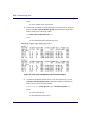
4-53
BSR Troubleshooting Guide
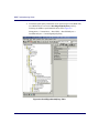
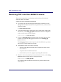
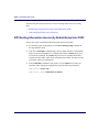
7. To find the signal quality information for an upstream port on the BSR 1000,
use a MIB browser to access the DocsIfSignalQualityEntry table by
following the MIB tree path identified below and in Figure 4-6:
Management -> Transmission -> DocsIfMib -> DocsIfMibObjects ->
DocsIfBaseObjects -> DocsIfSignalQualityEntry
Figure 4-6 DocsIfSignalQualityEntry Table
4-54
Troubleshooting the CMTS
8. View the signal quality statistics for the upstream interface. If there is a high
number of unerroreds (uncorrupted packets), the upstream signal-quality is
good.
Table 4-4 describes the signal quality statistics:
Table 4-4 Signal Quality Statistics
Field
Identification
correctables
Number of corrected error packets received through this upstream
interface
ifIndex
Cable interface number
unerroreds
Number of unerrored packets on cable interface
9. If there is a large number of correctables there is a physical problem with the
upstream signal. Use a spectrum analyzer to measure the signal to noise ratio
for the upstream path. For 16 QAM and QPSK, the optimum signal-to-noise
ratio is 33 dB or greater.
The signal-to noise ratio learned from the spectrum analyzer may indicate the
following conditions:
•
If there is under a 10 dB loss in signal quality, the cable interface has the
ability to compensate by correcting packets.
•
If there is more than a 10 dB loss in signal quality, the signal is degraded
to the point where it can no longer successfully carry data and the noise
problem has to be manually troubleshooted and corrected.
•
A high number of correctables (corrected packets) and uncorrectables
(uncorrected, dropped packets) occurs when the signal-to-noise ratio is
around 25 dB for QAM 16 and QPSK. The problem has to be manually
troubleshot and corrected. See if errors are incrementing from fixed points
in time in a higher than normal way.
•
The number of micro reflections expressed in dB, can correlate to a high
number of corrupted packets (erroreds) and fixed packets (correcteds), or
can be attributed to burst errors.
If there needs to be manual intervention to correct the upstream signal-to-noise
ratio, follow these steps to resolve a bad upstream signal-to-noise ratio:
4-55
BSR Troubleshooting Guide
1. Check for bad optical amplifiers in the HFC network.
2. Check for defective equipment in the HFC network.
3. Determine if there is a cable that is physically cracked or damaged in such a
way to cause external ingress from a variety of sources is entering into the
network.
4. Look for loose connections.
5. Study the HFC network topology and look for flaws that may be causing
additional ingress noise.
6. If there is too much ingress noise detected, increase the interleave depth.To set
the downstream port interleave depth, use the cable downstream
interleave-depth command in Interface Configuration mode, as shown below.
RDN(config-if)#cable downstream 0 interleave-depth {8 | 12 | 16 | 32
| 64 | 128}
where:
0 is the number of the downstream port.
7. If the cable plant is clean and the interleave depth is set too high, there may be
too much latency on the downstream path causing CMs to experience slow
performance. To decrease the interleave depth, use the cable downstream
interleave-depth command in Interface Configuration mode.
8. Determine if there are too many nodes that are combined on an upstream port.
Too much segmentation can affect the signal-to-noise ratio.
9. Check the individual nodes that are combined on an upstream port that is
experiencing ingress problems. For example, there may be three nodes that
have an acceptable signal-to-noise ratio, but the fourth node has a bad
signal-to-noise ratio that is cascading into the other three nodes and causing
poor performance on the upstream port.
10. Determine if impulse and electrical ingress noise is entering the network from
electrical sources within a home, such as hair dryers, light switches, and
thermostats; or from high-voltage lines that run near cabling in the network.
4-56
Troubleshooting the CMTS
Too Many CPE Hosts on Subscriber CM
When too many Customer Premises Equipment (CPE) hosts, such as PCs, servers,
and appliances are connected to a single subscriber’s CM, that CM can use an
excessive amount of network resources compared to other CMs on the HFC
subnetwork.
Follow these steps to view the number of CPE hosts for a CM, and to limit that
number:
1. To view the number of hosts connected to the CM, the maximum number of
hosts allowed for the CM, and a list of all host CPE IP addresses behind the
CM, use the show cable modem command in Privileged EXEC mode, as
shown in the following example:
RDN#show cable modem {<MAC-address> | <ip-address>} hosts
where:
MAC-address is the MAC level address of the CM.
ip-address is the IP address of the CM.
2. If you determine that there are too many CPE hosts connected to the CM, use
the cable modem max-hosts command in Privileged EXEC Mode, as shown
in the following example, to specify the maximum number of hosts that can be
attached to a CM on this interface. The valid range is from 0 to 16 CPEs. The
default value is zero.
RDN#cable modem {<MAC-address> | <ip-address>} max-hosts <n>
where:
MAC-address is the MAC level address of the CM
ip-address is the IP level address of the CM
n is the maximum number of CPE hosts for the CM
3. To verify the maximum number of hosts setting, use the show cable modem
hosts command in Privileged EXEC mode.
4-57
BSR Troubleshooting Guide
Resolving Problems on the Upstream Path
When the upstream port fault LED is red, the upstream port is not operating and is
not receiving data from the CM subnetwork.
Refer to the procedures in this section to troubleshoot an upstream port problem:
•
•
Bad Upstream Signal-to-noise Ratio Detected
Upstream Power Level Too Low or High
Bad Upstream Signal-to-noise Ratio Detected
If too much noise is detected on the upstream path a condition called noise
funneling occurs. Noise funneling occurs when the cumulative upstream noise
from anywhere on the HFC network becomes concentrated on the cable headend.
For example, the HFC branch and tree network architecture works in the following
ways:
•
Downstream: the trunk feeds the branches. As the signal propagates from the
trunk, the signal weakens.
•
Upstream: the branches feed the trunk. As the signal propagates from the
branches, noise and ingress increase.
Follow these steps to troubleshoot ingress noise on the upstream path:
1. To determine the modulation profile number for an upstream port, use the
show cable upstream command in Interface Configuration mode, as shown in
the following example:
RDN(config-if)#show cable <slot>/<interface> upstream <port>
where:
slot is the slot number of the DOCSIS module on the BSR 64000
4-58
Troubleshooting the CMTS
interface is the number of the cable interface
Note: The slot and interface number on the BSR 1000 are 0.
port is the number of the upstream port
2. To view the modulation profile for the upstream port to determine whether
QAM 16 or QPSK modulation is used on the upstream interface, use the show
cable modulation-profile command in Privileged EXEC mode as shown in
the following example:
RDN#show cable modulation-profile <n>
where:
n is the modulation profile number
3. View the show cable modulation-profile command output to determine
whether the upstream modulation is 16 QAM or QPSK.
4. To determine the signal quality on the upstream port, use the show interfaces
cable signal-quality command in Privileged EXEC mode, as shown in the
following example:
RDN#show cable interface <slot>/<port> signal-quality
where:
slot is the slot number of the DOCSIS module on the BSR 64000
Note: The BSR 1000 uses the same syntax as the above command,
however both the slot number and interface number are set to zero.
interface is the cable interface number
Signal quality statistics for all the upstream interfaces (ports) displays.
4-59
BSR Troubleshooting Guide
5. View the show cable interface signal-quality statistics for the specific
upstream interface. If there is a high number of unerroreds (uncorrupted
packets), the upstream signal-quality is good.
Table 4-4 describes the show cable interface signal-quality statistics:
Table 4-5 show cable interface signal-quality Command Output Statistics
Field
Identification
correctables
Number of corrected error packets received through this upstream
interface
ifIndex
Cable interface number
unerroreds
Number of unerrored packets on cable interface
6. If there is a large number of correctables there is a physical problem with the
upstream signal. Use a spectrum analyzer to measure the signal to noise ratio
for the upstream path. For 16 QAM and QPSK, the optimum signal-to-noise
ratio is 33 dB or greater.
The signal-to noise ratio learned from the spectrum analyzer may indicate the
following conditions:
•
If the loss in signal quality is less than 10dB, the cable interface can
compensate by correcting packets.
•
If the loss in signal quality is greater than 10 dB, the signal is degraded to
the point where it can no longer carry data, and you must troubleshoot and
correct the noise problem.
•
A high number of correctables (corrected packets) and uncorrectables
(uncorrected, dropped packets) occurs when the signal-to-noise ratio is
approximately 25 dB for QAM 16 and QPSK. You must manually
troubleshoot and correct the problem. See if errors increment at a specific
time at a higher than expected rate.
•
The number of micro reflections (expressed in dB) can signify a high
number of corrupted packets (erroreds) and fixed packets (correcteds).
Follow these steps to manually resolve an upstream signal-to-noise ratio problem:
4-60
Troubleshooting the CMTS
1. Inspect optical amplifiers in the HFC network to make sure they are working
properly.
2. Make sure all HFC network equipment is working properly.
3. Inspect cables for damage.
4. Secure all cable connections.
5. Review the HFC network topology and identify any flaws that may cause
additional ingress.
6. Determine if there are too many nodes on an upstream port. Too much
segmentation can affect the signal-to-noise ratio.
7. Check the individual nodes on an upstream port that is experiencing ingress
problems. For example, three nodes may have an acceptable signal-to-noise
ratio, but the fourth node might have a bad signal-to-noise ratio that is
cascading into the other three nodes and causing poor performance on the
upstream port.
8. Determine if impulse and electrical ingress noise is entering the network from
electrical sources within a home (such as hair dryers, light switches, and
thermostats), or from high-voltage lines near network cabling.
Upstream Power Level Too Low or High
The cable interface controls CM output power levels to meet the desired upstream
input power level. Input power level adjustments to an operational upstream port
compensate for cable headend path loss between the optical receiver and the
upstream RF port. This section describes how to troubleshoot physical problems
that may affect power levels on the upstream channel.
4-61
BSR Troubleshooting Guide
This section also describes how to configure the upstream input power level when
problems occur. The upstream input power level is configured in either an
absolute or relative mode. If the upstream input power level is set in relative
mode, the input power level changes when the upstream channel width is changed.
If the upstream input power level is set to the absolute mode, the input power level
does not change when the upstream channel width is changed. Defining the input
power level in absolute mode could possibly cause upstream return lasers to clip
on a completely populated upstream channel. Caution must be used when the input
power level is increased in absolute mode because the CMs on the HFC network
increase their transmit power level by 3 dB for every incremental upstream
channel bandwidth change causing an increase in the total power on the upstream
channel and possibly violating the upstream return laser design parameters.
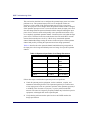
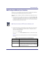
Table 4-6 describes how the upstream channel bandwidth setting corresponds to
the input power-level range and default power-level range for a specific upstream
channel.
Table 4-6 Upstream Input Power Level Range Parameters
Channel Bandwidth Default
Range
200 KHz
-1 dBmV
-16 to +14
dBmV
400 KHz
+2 dBmV
-13 to +17
dBmV
800 KHz
+5 dBmV
-10 to +20
dBmV
1.6 MHz
+8 dBmV
-7 to +23 dBmV
3.2 MHz
+11 dBmV
-4 to +26 dBmV
Follow these steps to troubleshoot upstream power-level problems:
1. Check all upstream passive equipment, such as combiners, couplers, and
attenuators and cabling for flaws. The upstream signal may be weak because
of low input power levels on a portion or portions of the upstream spectrum (5
to 42 MHz). This is known as a frequency response problem in the HFC
network. The cause of a frequency response problem may be defective passive
equipment, or damaged cable on the upstream path.
2. Verify that the path between the optical receiver and CMTS matches the
design specification.
4-62
Troubleshooting the CMTS
3. Inspect amplifiers if there is an attenuation problem on the upstream path.
View CMs that proceed or follow an amplifier in the upstream path to isolate
the defective amplifier and replace or repair it. Look for amplifier degradation.
Improperly configured amplifiers can degrade digital data signals. The larger
the network, the higher the possibility of amplifier noise affecting the signals.
4. Be aware of thermal sensitivity. Signal loss over coaxial cable is affected by
temperature. This can cause variations of 6 to 10 dB per year.
5. Inspect the upstream physical cabling and passive equipment to be sure it is in
good condition. If the problem persists, check the upstream input power-level
configuration.
6. To adjust the upstream input power level in relative mode, use the cable
upstream power level default command in Interface Configuration mode, as
shown in the following example:
RDN(config-if)#cable upstream <n> power-level default <offset>
where:
n is the number of the upstream port
offset is the number of dB above or below the default input power level
7. To set the upstream input power level in absolute mode, use the cable
upstream power level command in Interface Configuration mode, as shown
in the following example:
RDN(config-if)#cable upstream <n> power-level <power>
where:
n is the number of the upstream port
power is the input power level expressed in dB
Resolving Problems on the Downstream Path
When the downstream port fault LED is red, the downstream port is not operating
and is not sending data to the CM subnetwork.
Refer to the procedures in this section to troubleshoot a downstream port problem:
4-63
BSR Troubleshooting Guide
•
•
Bad Downstream Signal-to-Noise Ratio Detected
Downstream Power Level Too Low or High
Bad Downstream Signal-to-Noise Ratio Detected
Follow these steps to identify problems associated with a bad downstream
signal-to-noise ratio:
1. To determine the type of Quadrature Amplitude Modulation (QAM) that is
used on the downstream interface, use the show cable downstream command
in Interface Configuration mode, as shown in the following example:
RDN(config-if)#show cable downstream <n>
where:
n is the number of the downstream cable port.
2. View the qamMode field in the show cable downstream command output.
The qamMode field displays whether the downstream modulation is 64 QAM
or 256 QAM.
3. Isolate the CM on the network that is experiencing ingress problems, such as
degraded performance or connection difficulties.
4. To get the CM MAC or IP address, use the show cable modem command in
Privileged EXEC mode, as shown in the following example:
RDN(config-if)#show cable modem
5. Use a spectrum analyzer to determine the downstream signal quality. For 256
QAM, the optimum signal-to-noise ratio is 33 dB or greater. For 64 QAM, the
optimum signal-to-noise ratio is 25 dB or greater.
The signal-to noise ratio learned from the spectrum analyzer may indicate the
following conditions:
4-64
•
If the loss in signal quality is less than 10 dB, the cable interface can
compensate by correcting packets.
•
If the loss in signal quality is greater than 10 dB, the signal is degraded to
the point where it can no longer carry data, and you must troubleshoot and
correct the noise problem.
Troubleshooting the CMTS
•
A high number of corrected packets and uncorrected, dropped packets
occurs when the signal-to-noise ratio is approximately 25 dB for 256
QAM, and 20 dB for 64 QAM. You must manually troubleshoot and
correct the problem. See if errors increment at a specific time at a higher
than expected rate.
•
The micro reflections number (expressed in dB) represents the amount of
noise on the cable interface, and corresponds to a high number of
corrupted packets (erroreds) and fixed packets (correcteds).
Follow these steps to manually resolve a downstream signal-to-noise ratio
problem:
1. At the cable headend, make sure that the power levels of adjacent channels do
not interfere with the downstream channel.
2. Inspect optical amplifiers in the HFC network to make sure they are working
properly.
3. Make sure all HFC network equipment is working properly.
4. Inspect cables for damage.
5. Check for laser clipping on fiber-optic transmitters on the downstream path
from the cable headend to the CMs. If the downstream power level is too high
for the downstream path, laser clipping can occur. Laser clipping prevents the
transmission of light, which can cause bit errors in downstream transmissions.
If a laser is experiences excessive input power for even a fraction of a second,
clipping can occur. Refer to the Downstream Power Level Too Low or High
section for more troubleshooting information.
6. Secure all cable connections.
7. Review the HFC network topology to identify any flaws that may cause
additional ingress.
8. Determine if impulse and electrical ingress noise is entering the network from
electrical sources within a home (such as hair dryers, light switches, and
thermostats) or from high-voltage lines near network cabling.
Downstream Power Level Too Low or High
Follow these steps to troubleshoot downstream power-level problems:
4-65
BSR Troubleshooting Guide
1. Check all downstream passive equipment (such as combiners, couplers, and
attenuators) and cabling for flaws. The downstream signal may be weak
because of a low power level on a portion of the downstream spectrum
(88-860 MHz). This is known as a frequency response problem on the HFC
network. The cause of a frequency response problem may be defective passive
equipment, or damaged cable on the downstream path.
2. If the downstream physical cabling and passive equipment is in good
condition and the problem persists, check the downstream input power-level
configuration.
To set the downstream power level to a value from 45 to 65 decibels per
millivolt (dBmV), use the cable downstream power-level command, as
shown below:
RDN(config-if)#cable downstream <n> power-level {450-650}
where:
n is the number of the downstream cable port.
450-650 is the downstream power level
Note: The downstream power level must be expressed in increments of
ten.
To return to the 55 dBmV default power-level setting, use the no cable
downstream power-level command in Interface Configuration mode, as
shown below:
RDN(config-if)#no cable downstream <n> power-level {450-650}
where n is the number of the downstream cable port.
3. Check for laser clipping on fiber-optic transmitters on the downstream path
from the cable headend to the CMs. If the downstream power level is set too
high for the downstream path, laser clipping can occur. Laser clipping
prevents the transmission of light, which can cause high bit error rates on the
downstream path.
4-66
Troubleshooting the CMTS
4. Inspect amplifiers if there is an attenuation problem on the downstream path.
View CMs that proceed or follow an amplifier in the downstream path to
isolate the defective amplifier and replace or repair it. Look for amplifier
degradation. Improperly configured amplifiers can degrade digital data
signals. The larger the network, the higher the possibility of amplifier noise
affecting the signals.
5. Be aware of thermal sensitivity: signal loss over coaxial cable is affected by
temperature. This can cause variations of 6 to 10 dB per year. The downstream
power level may need seasonal adjustment.
Resolving Cable Modem Problems
If CMs are not registering and cannot communicate with the cable interface, the
problem may be one of the following:
•
•
•
•
•
•
Misconfigured Authentication String or Key
CM Does Not Reply to Station Maintenance Requests
CM is Offline
CM Cannot Obtain an IP Address
Provisioning Problems Cause CMs Not to Register
CM Does Not Respond to SNMP Messages
Misconfigured Authentication String or Key
All CMs must return a known authentication text string or key to register with the
cable interface for network access. If the text string or key is improperly entered,
the CMs cannot authenticate and register with the cable interface.
Follow these steps to re-enter the shared authentication text string or key so that
the CMs can authenticate and register with the cable headend:
1. Ensure that the authentication string or hexadecimal key in the CM
configuration file matches the authentication string or hexadecimal key
configured on the CMTS. CMs cannot register with the CMTS if
authentication parameters do not match.
4-67
BSR Troubleshooting Guide
2. To verify that CM authentication is deactivated, use the show running-config
command in Privileged EXEC mode and view the cable interface
configuration information. The output will show if CM authentication is
deactivated.
RDN#show running-config
3. To enter Interface Configuration mode from Global Configuration mode to
configure the cable interface, use the interface cable command, as shown in
the following example:
BSR64000(config)#interface cable {<slot number>/<interface number>}
where:
slot number refers to the DOCSIS module slot number on the BSR 64000
interface number refers to the cable interface
Note: The BSR 1000 uses the same syntax as the above command,
however both the slot number and interface number are set to zero.
4. The default authentication parameters are enabled, but have a null value by
default. Authentication parameters need to be set on the CMTS and the CMs
to ensure security on the HFC network. To activate authentication on the
CMTS so all CMs return a known text string to register with the CMTS for
network access, use the cable shared-secret command in Interface
Configuration mode, as shown in the following example:
Caution: Ensure that the authentication string or hexadecimal key in the
CM configuration file matches the authentication string or hexadecimal
key configured on the CMTS. CMs cannot register with the CMTS if
authentication parameters do not match.
RDN(config-if)#cable shared-secret [n] [<“authentication string”> |
<0xkey>]
where:
n is the number of the shared secret
4-68
Troubleshooting the CMTS
“authentication string” is an alpha-numeric text string specified in double
quotes
0xkey is a key specified in hexadecimal notation
5. To restore the default CM authentication, which is a null value, use the no
cable shared-secret command in Interface Configuration mode, as shown in
the following example:
BSR64000(config-if)#no cable shared-secret [ <“authentication
string”> | <hexidecimal key> ]
6. To verify that CM authentication is activated, use the show running-config
command in Privileged EXEC mode and view the cable interface
configuration information. If CM authentication is active, authentication
information does not appear in the show running-config command output.
BSR64000#show running-config
CM Does Not Reply to Station Maintenance Requests
If a CM does not reply to station maintenance requests after 16 retries, the cable
interface assumes that it is offline. The cable interface marks the CM Service
Identifier (SID) state offline, removes the SID from the ranging list and starts an
aging timer to clear the SID if the CM does not come online within 24 hours.
Follow these steps to solve CM station maintenance registration problems:
1. To identify registration problems concerning CMs connected to the cable
interface, use the show cable modem command in Privileged EXEC mode, as
shown in the following example:
RDN#show cable modem
2. To view the SID status of a CM that is marked offline by the cable interface,
use the show cable modem detail command, as shown in the following
example:
RDN#show cable modem detail [<mac-address> | <slot>/<interface>] <n>
where:
4-69
BSR Troubleshooting Guide
slot is the slot number of the DOCSIS module on the BSR 64000
Note: The BSR 1000 uses the same syntax as the above command,
however both the slot number and interface number are set to zero.
interface is the number of the cable interface
n is the SID number for the CM
The SM Exhausted Count value in the command output refers to the number
of times a CM was dropped because it did not reply to station maintenance
requests.
The SM Aborted Count value in the command output refers to the number of
times the CM was dropped because of unacceptable operating parameters.
This can occur if the power level is outside the acceptable range, or the timing
offset changes. The command output indicates the times when this occurs.
CM is Offline
If a CM is offline, it is disconnected from the network and unable to register.
Ping the CM to determine if the connection between the cable interface and the
CM is online. A CM may appear to be offline if it does not have an IP address and
is not registering; however, it may still be online. Pinging is necessary when the
following symptoms occur:
•
•
•
CM is unable to complete registration.
CM has internal bugs.
CM is unresponsive due to a crash.
The ping feature includes a real-time view and plot of requested power
adjustments. It also measures the optimal headend reception power that allows the
cable interface to solicit a configurable number of periodic ranging requests from a
CM.
4-70
Troubleshooting the CMTS
1. To ping a specific CM IP address or hostname to determine if the CM is
online, use the ping command in Privileged EXEC mode, as shown in the
following example:
RDN#ping {<ip-address> | <hostname>}
where:
ip-address is the IP address of the CM
hostname is the DNS hostname of the CM
Note: You must use a IP address for the CM you are pinging. If you
cannot ping the CM using its IP address, the CM is not registering.
2. If there is no IP level conectivity, but you suspect the CM has connectivity at
the MAC layer, use the ping docsis command in to ping a specific CM at the
MAC layer:
RDN(config-if)#ping docsis [<mac-address> | <ip-address>]
Note: Be sure to use the correct MAC or IP address of the CM.
3. Determine if the CM is having registration problems by using the debug cable
reg command in Interface Configuration mode, as shown in the following
example:
RDN#debug cable reg
4. To reset a specific CM by using its MAC address, use the clear cable modem
reset command in Privileged EXEC mode, as shown in the following
example:
RDN#clear cable modem [<MAC-address> | <ip-address>] reset
where:
4-71
BSR Troubleshooting Guide
MAC-address is the MAC level address of the CM.
ip-address is the IP level address of the CM.
Note: It may take up to 30 seconds for the CM to respond and start the
reset sequence.
5. If all CMs are unable to obtain an IP address, use the clear cable modem all
reset command to remove all CMs from the station maintenance list and reset
them:
RDN(config-if)#clear cable modem all reset
CM Cannot Obtain an IP Address
When a CM is unable to obtain an IP address it cannot successfully register and
connect to the HFC network. Follow these steps to reset the CM:
1. To determine if a CM or several CMs are having registration problems, use the
debug cable reg command in Interface Configuration mode, as shown in the
following example:
RDN#debug cable reg
2. To force the CM to reset if the CM does not have an IP address, use the clear
cable modem command in Privileged EXEC mode as shown in the following
example:
RDN#clear cable modem <mac-address> reset
where:
mac-address is the MAC address of the CM
Note: It may take up to 30 seconds for the CMs to respond and start the
reset sequence.
4-72
Troubleshooting the CMTS
3. If the CM has an IP address and must be reset, use the clear cable modem
reset command in Privileged EXEC mode as shown in the following example:
RDN#clear cable modem <ip-address> reset
where:
ip-address is the IP address of the CM
4. If all CMs are unable to obtain an IP address, use the clear cable modem all
reset command to remove all CMs from the station maintenance list and reset
them:
RDN(config-if)#clear cable modem all reset
5. If CMs still cannot obtain an IP address, there may be a problem with the
DHCP server or the provisioning configuration. Ensure that the DHCP server
is operational and configured correctly. Refer to Provisioning Problems Cause
CMs Not to Register section for more information.
6. To verify that a particular CM obtained an IP address, enter the show cable
modem command in Privileged EXEC mode, as shown in the following
example:
RDN#show cable modem <mac-address>
where:
mac-address is the MAC address of the CM.
4-73
BSR Troubleshooting Guide
Provisioning Problems Cause CMs Not to Register
It is important to understand the basic communication process between the CM,
cable interface on the BSR, and the DHCP server to troubleshoot provisioning
problems.
The DHCP portion of the CM registration process works as follows:
1. The CM sends a broadcast discovery message to the DHCP server.
2. The DHCP server sends an offer message to the CM that identifies that the
DHCP server is “alive,” and presents connectivity information to the CM.
3. The CM sends a request message to use the information received in the offer
message, and asks for options such as the default gateway, TFTP,
configuraiton file, etc.
4. The DHCP server acknowledges the request, and provisions the CM with an
IP address so that the CM can use TFTP to continue the registration process
and returns options.
Follow these steps to identify CM registration problems associated with
provisioning:
1. To review information about a CM attempting to register with the cable
interface, use the show cable modem command in Privileged EXEC mode, as
shown in the following example:
RDN#show cable modem <MAC address>
2. View the Connectivity State column in the show cable modem command
output.
3. Determine whether the cable interface is receiving a DHCP discover message
from the CM. If the cable interface has received a DHCP discover message
from the CM, a range complete message displays in the connectivity state
column.
4. To show all DHCP traffic traversing the cable interface, use the debug ip udp
dhcp command in Privileged EXEC mode, as shown in the following
example:
RDN#debug ip udp dhcp
4-74
Troubleshooting the CMTS
5. If the cable interface is receiving a DHCP discover message from the CM,
determine if the cable interface is forwarding DHCP discover messages to the
DHCP server by checking if the DHCP sever is receiving DHCP discover
packets and if it is sending DHCP offer packets to the CM.
a. If the DHCP server is receiving DHCP discover messages from the
CM, the DHCP server can reply by sending a DHCP offer. However, if
the DHCP server is not receiving DHCP discover messages from the
CM through the cable interface, the cable helper IP address may not be
configured properly. Refer to Step 6 for more information.
b. If the DHCP server is receiving DHCP discover messages from the
CM, but is not sending DHCP offer messages, the DHCP server is
misconfigured. Make sure that the DHCP is configured to service the
subnet associated with the CM.
c.
If the CM receives a DHCP offer, the CM sends a DHCP request
message to the DHCP server so that it can use the information received
in the offer message. When the DHCP server acknowledges the
request, it provisions the CM with an IP address so that the CM can use
TFTP to continue the registration process. If the CM is able to obtain
an IP address, but is unable to complete the registration process, make
sure that the TFTP server IP address and CM configuration file name,
including the full path from the TFTP root directory, are properly
configured.
6. If there is no communication between the DHCP server and the cable
interface, the CM does not have an IP address. Determine if DHCP parameters
are set correctly on the cable interface. The ip helper-address command is
used to disassemble a cable modem’s DHCP broadcast packet, and reassemble
the DHCP broadcast packet into a unicast packet so that the packet can
traverse through the router and communicate with the DHCP server.
To configure the helper IP address for the cable modems (CMs) to forward
only UDP broadcasts, use the ip helper-address cable-modem command in
Interface Configuration mode, as shown in the following example:
RDN(config-if)#ip helper-address <ip-address> cable-modem
where:
ip-address is the IP address of the destination DHCP server
4-75
BSR Troubleshooting Guide
7. If there is no communication between the TFTP server and the cable interface, the
CM does not have an IP address. Determine if TFTP parameters are set correctly
on the cable interface.
To configure the helper IP address for the cable modems (CMs) to forward only
UDP broadcasts, use the cable helper-address cable-modem command in
Interface Configuration mode, as shown in the following example:
RDN(config-if)#cable helper-address <ip-address> cable-modem
where:
ip-address is the IP address of the destination TFTP server
8. If CMs are registering successfully but there is no Customer Premises Equipment
(CPE) connectivity, the helper IP address for the CPE must be configured. To set
the helper IP address for the CPE behind a CM to forward only UDP broadcasts,
use the cable helper-address host command in Interface Configuration mode, as
shown in the following example:
RDN(config-if)#cable helper-address <ip-address> host
where:
ip-address is the IP address of the destination TFTP server
9. If the DHCP server is operating correctly, but a CM remains unresponsive, reset
the CM so that it can obtain a new IP address.
To reset a CM, use the clear cable modem reset command in Privileged EXEC
mode, as shown in the following example:
RDN#clear cable modem <mac-address> reset
where:
mac-address is the MAC address of the CM
Note: Be sure to correctly enter the CM MAC address in the command. It
may take up to 30 seconds for the CM(s) to respond and start the reset
sequence.
4-76
Troubleshooting the CMTS
10. To reset all CMs so that they can obtain an IP address, use the clear cable
modem all reset command in Privileged EXEC mode:
RDN#clear cable modem all reset
11. If you have exhausted all the provisioning troubleshooting possibilities for
CM registration problems, refer to other sections in this chapter for help on
troubleshooting the upstream path from the CM to the cable interface.
CM Does Not Respond to SNMP Messages
Follow these steps to correct a CM that is not responding to SNMP messages:
1. To reset the CM so that it can respond to SNMP messages, use the clear cable
modem reset command in Privileged EXEC mode:
RDN#clear cable modem <MAC-address> reset
Note: Be sure to correctly enter the CM MAC address. It may take up to
30 seconds for the CM(s) to respond and start the reset sequence.
2. To reset all CMs so that they can respond to SNMP messages, use the clear
cable modem all reset command in Privileged EXEC mode, as shown in the
following example:
RDN#clear cable modem all reset
3. To verify that the clear cable modem all reset command enabled CMs to
respond to SNMP messages, enter the show cable modem command in
Privileged EXEC mode.
4. Make sure that the community names for SNMP Version 1 and SNMP
Version 2 and the user name for SNMP Version 3 are correct.
4-77
BSR Troubleshooting Guide
4-78
5
Troubleshooting TCP/IP
Troubleshooting TCP/IP
Introduction
This chapter provides troubleshooting solutions to some common TCP/IP
internetwork problems:
•
•
•
•
•
•
•
Resolving Host Connectivity Problems
Handling Routing Problems
Misconfigured Router
Handling a Misconfigured Access List
Access List and Filter Misconfigurations
Handling UDP Broadcast Forwarding Problems
Resolving PPP Link Over SONET Failures
Resolving Host Connectivity Problems
The following sections provide instructions for resolving local and remote host
connectivity problems:
•
•
•
•
Default Gateway Configuration Problems
Misconfigured or Missing Default Routes
Incomplete DNS Host Table
DNS Not Running
Default Gateway Configuration Problems
If a local host cannot access a remote host, the default gateway might not be
specified, or the default gateway could be incorrectly configured on local or
remote host.
Note: This chapter presents host configuration solutions from a UNIX
perspective. If you are working with a PC, consult the corresponding
documentation to determine how to set the default gateway IP address.
5-81
BSR Troubleshooting Guide
Follow these steps to configure a default gateway for a local or remote host:
1. To determine whether the local and remote hosts have a default gateway, use
the netstat -rn command at the UNIX prompt, as shown in the following
example:
unix-host% netstat -rn
Check the output of this command for a default gateway specification.
2. If the default gateway specification is incorrect or not present, change or add a
default gateway, as shown in the following example using the route add
default command at the UNIX prompt on the local host:
unix-host% route add default <ip-address> <n>
where:
ip-address is the IP address of the default gateway (the router local to the
host).
n indicates the number of hops to the specified gateway.
Note: You may need to reboot the host for this change to take effect.
3. You should specify a default gateway as part of the boot process. Specify the
IP address of the gateway in the /etc/defaultrouter UNIX host file. This
filename might be different on your UNIX system.
Misconfigured or Missing Default Routes
Follow these steps to resolve misconfigured or missing default routes:
1. To view the host routing table (if the host is routed), use the netstat -rn
command at the UNIX prompt, as shown in the following example:
unix-host% netstat -rn
The entry with the destination default denotes the default route.
5-82
Troubleshooting TCP/IP
2. The default route entry should specify the router that has the route to the
remote host. If there is no default route entry, use the route add default
command at the UNIX prompt to manually configure the default gateway:
unix-host% route add default <ip-address> <n>
where:
ip-address is the IP address of the default gateway (the router local to the
host).
n indicates the number of hops to the specified gateway.
Note: You may need to reboot the host for this change to take effect.
Incomplete DNS Host Table
If the Domain Name Server (DNS) receives a lookup request for a host name that
is not in its cache, it cannot reply to the request, and the client cannot establish a
connection.
Follow these steps to complete the DNS host table:
1. Enter the following host command at the UNIX prompt:
unix-host% host <ip-address>
where:
ip-address is the IP address of a server, router, or other network node.
2. If a Host not found message displays, but you can open the connection
using the host’s IP address rather than its name, try connecting to other hosts
using their names. If you can open connections to other hosts using their
names, the host table might be incomplete. Add hostname-to-address
mappings to the DNS cache for every host on the network.
3. If any connections cannot be opened using host names, the DNS might not be
running. Refer to DNS Not Running, for more troubleshooting information.
5-83
BSR Troubleshooting Guide
DNS Not Running
If issuing the host command at the UNIX prompt returns a Host not found
message, but you are able to open a connection using the host’s IP address, the
DNS might not be running. Consult the DNS software documentation or your
system administrator for information on configuring and enabling the DNS.
Handling Routing Problems
The following sections describe how to re-enable a problem router and correct
network router configuration problems that can occur after a new interface is
added to a router:
•
•
•
Problem Router
Misconfigured Router
Routing Interface Down
Problem Router
Follow these steps to enable a router that is having problems:
1. To isolate the problem router, use the traceroute command in Privileged
EXEC mode, as shown in the following example:
RDN#traceroute {<hostname> | <ip-address>}
where ip-address is the destination IP address or host name on the command
line.
Table 5-1 describes the traceroute command output field descriptions:
Table 5-1 traceroute Command Output Field Descriptions
5-84
Field
Description
nn/msec
For each node, the round trip time in milliseconds for the specified number
of probes.
*
The probe timed out.
?
Unknown packet type.
Troubleshooting TCP/IP
Table 5-1 traceroute Command Output Field Descriptions
Field
Description
Q
Source quench.
P
Protocol unreachable.
N
Network unreachable.
U
Port unreachable.
H
Host unreachable.
2. Once you isolate a problem router, determine whether routing is enabled on
the BSR. To view the routing table, enter the show ip route command in
Privileged EXEC mode, as shown in the following example:
RDN#show ip route
Examine the command output to see whether the routing table is populated
with routing information. If the command output displays no entries, the
routing information is not being exchanged.
3. If the routing information is not being exchanged, a routing interface may not
be configured.
4. To configure a routing interface, use the interface ethernet command, as
shown in the following example:
RDN(config)#interface ethernet 7/0
where:
7 is the SRM slot and 0 is the ethernet interface on the BSR 64000.
Note: The BSR 1000 uses the same syntax, however the ethernet slot
and port are each set to zero.
5. To set the IP address and subnet mask for a routing interface, use the ip
address command, as shown in the following example:
RDN(config-if)#ip address 10.10.10.92 255.255.255.0
5-85
BSR Troubleshooting Guide
6. To enable the proper routing protocol on the router interface, use the router
command in Global Configuration mode, as shown in the following example.
The following example shows how to enable the RIP routing protocol on the
router interface.
RDN(config)#router rip
Note: The Autonomous System (AS) number needs to be entered when
enabling BGP. The AS applies to BGP only.
7. To determine the network on which the routing protocol is running, use the
network command, as shown in the following example. The following
example shows how to enable the RIP routing protocol on the 10.10.10
network:
RDN(config-rip)#network 10.10.10.0 255.255.255.0
8. Check if one or more networks need to be associated with the appropriate
routing protocol. For example, to enable RIP routing for hosts 10.10.10.0 and
10.10.20.0, enter the following configuration commands:
RDN(config)#router rip
RDN(config-rip)#network 10.10.10.0 255.255.255.0
RDN(config-rip)#network 10.10.20.0 255.255.255.0
Misconfigured Router
Follow these steps to resolve misconfigured or missing router command that can
cause routes to be missing from routing tables:
1. To check routing tables on routers, use the show ip route command in
Privileged EXEC mode.
2. Determine whether there are missing routes to specific networks that are
known to be connected.
3. Reconfigure the identified missing routes so that they are associated to their
designated network.
5-86
Troubleshooting TCP/IP
4. To view a specific router configuration, use the show running-config
command in Privileged EXEC mode.
5. Try to ping another device that is on the same network that has a routing
problem.
6. Make sure that there is a network router configuration command specified for
the network to which the interface belongs. For example, if you assign the new
interface IP address 10.10.10.0, enter the following commands to enable RIP
on the interface:
RDN(config)#router rip
RDN(config-rip)#network 10.10.10.5 255.255.255.0
Ensure that process IDs, addresses, and other variables are properly specified
for the routing protocol you are using.
Routing Interface Down
Use the following steps to activate a routing interface:
1. Use the show ip interfaces brief command in Privileged EXEC mode to see
whether the interface is administratively down, as shown in the following
example:
RDN#show ip interfaces brief
Check the command output to determine if the Ethernet or POS interface is
administratively down.
2. If the interface is administratively down, bring it up using the no shutdown
command in Interface Configuration mode, as shown in the following
example:
RDN(config)#interface {<interface> | <slot>/<interface number>}
where:
interface is either identified as ethernet or POS.
slot number refers to the POS, or SRM module slot number on the BSR
64000.
5-87
BSR Troubleshooting Guide
interface number refers to the ethernet or POS interface number.
Note: The BSR 1000 uses the same syntax as the above command,
however the ethernet interface slot and interface number are set to zero.
RDN(config-if)#no shutdown
3. To discover if the router interface is enabled, use the show ip interfaces brief
command in Privileged EXEC mode. If the interface is still down, there might
be a hardware or media problem.
5-88
Troubleshooting TCP/IP
Handling a Misconfigured Access List
Access lists are used to filter IP packets so that certain IP packets are denied or
permitted. Follow these steps to troubleshoot a misconfigured access list:
1. To determine whether IP packets are being sent and received and whether
there are encapsulation problems, use the debug ip packet command in
Privileged EXEC mode.
Caution: Debug commands can use considerable CPU resources on the
router. Do not execute them if the network is already heavily congested.
2. If a router appears to be sending IP packets, but a connected router does not
receive them, check the configuration of the connected router for access lists
that might be filtering out packets.
3. To enter the router interface, use the interface command in Global
Configuration mode, as shown in the following example:
RDN(config)#interface {<interface> | <slot>/<interface number>}
where:
interface is either identified as ethernet or POS.
slot number refers to the POS, or SRM module slot number on the BSR
64000.
interface number refers to the ethernet or POS interface number.
Note: The BSR 1000 uses the same syntax as the above command,
however the ethernet interface slot and interface number are set to zero.
4. To disable all access lists enabled on the router, use the no ip access-group
access-list command in Ethernet, Cable or POS Interface Configuration mode,
as shown in the following example:
5-89
BSR Troubleshooting Guide
RDN(config-if)#no ip access-group <group number> access-list
[extended | standard] <list number>
where:
group number is the ip access group
extended or standard is selected for an access list
list number is the access list number
5. Execute the debug ip packet command to determine whether the router is
receiving packets.
6. If the router is receiving packets an access list is probably filtering packets. To
isolate the problem list, enable access lists one at a time until packets are no
longer forwarded by using the distribute-list command in Router
Configuration mode, as shown in the following example:
RDN(config)#router <protocol>
where protocol is the routing protocol used.
RDN(config-router)#distribute-list [extended | standard] | <list number>
where:
extended or standard is selected as the type of distribute list
list number is the access list number.
7. Check the access list to see whether it is filtering traffic from the source router.
If it is, alter the access list to allow the traffic to pass. Enter explicit permit
statements for traffic that you want the router to forward normally.
8. To enable the altered access list to see whether packets continue to pass
normally, use the ip access-group access-list command in Router
Configuration mode, as shown in the following example:
RDN(config-router)#ip access-group <group number> access-list <list
number>
where:
group number is the ip access group
list number is the access list number
5-90
Troubleshooting TCP/IP
9. If packets pass normally, perform steps 1 to 7 on any other routers in the path
until all access lists are enabled and packets are forwarded properly.
Access List and Filter Misconfigurations
Application errors that drop host connections are frequently caused by
misconfigured access lists or other filters.
Follow these steps to fix access lists or other filters:
1. Use the show running-config command in Privileged EXEC mode to check
each router in the path. Discover if there are IP access lists configured on the
BSR.
2. If IP access lists are enabled on the BSR, disable them using the appropriate
commands. An access list may be filtering traffic from a TCP or UDP1 port.
For example, to disable input access list 80, enter the following command in
Router Interface configuration mode:
RDN(config-if)#no ip access-group 80 in
3. After disabling all the access lists on the BSR, determine whether the
application operates normally.
If the application operates normally, an access list is probably blocking traffic.
4. To isolate the problem list, enable access lists one at a time until the
application no longer functions. Check the problem access list to determine
whether it is filtering traffic from any TCP or UDP ports.
5. If the access list denies specific TCP or UDP ports, make sure that it does not
deny the port used by the application in question (such as TCP port 23 for
Telnet).
6. Enter explicit permit statements for the ports the applications use. The
following commands allow DNS and NTP2 requests and replies:
RDN(config-if)#access-list <list number> permit udp 0.0.0.0
255.255.255.255 0.0.0.0 255.255.255.255 eq 53
RDN(config-if)#access-list <list number> permit udp 0.0.0.0
255.255.255.255 0.0.0.0 255.255.255.255 eq 123
5-91
BSR Troubleshooting Guide
7. If you altered an access list, enable the list to see whether the application can
still operate normally.
8. If the application operates normally, repeat the previous steps to isolate any
other problem access lists until the application operates correctly with all
access lists enabled.
Handling UDP Broadcast Forwarding Problems
The User Datagram Protocol (UDP) describes how messages reach application
programs within a destination computer. The following sections describe how to
solve problems that occur when forwarding BOOTP or other UDP broadcast
packets. For example, if UDP broadcasts sent from network hosts are not
forwarded by routers, or diskless workstations cannot boot.
•
•
Missing or Misconfigured IP Helper-address Specification
UDP Broadcast Misconfiguration
Missing or Misconfigured IP Helper-address Specification
1. Use the debug ip udp command in Privileged EXEC mode on the BSR that
should be receiving packets from the host. Check the output of the command
to see whether the BSR is receiving packets from the host.
Caution: The debug ip udp command can use considerable CPU
resources on the BSR. Do not execute the command if the network is
heavily congested. If the network is congested, attach a protocol analyzer
to see whether the BSR is receiving UDP broadcasts from the host.
2. If the router receives packets from the host, there is a problem with the host or
the application. Consult the host or application documentation.
3. If the router does not receive packets from the host, use the show
running-config command in Privileged EXEC mode to check the
configuration of the router interface that should first receive the packet from
the host.
5-92
Troubleshooting TCP/IP
4. Look for an ip helper-address command entry for that router interface. Make
sure that the specified address is correct (it should be the IP address of a server
application such as a BOOTP server). If there is no command entry, no helper
address is configured.
5. If there is no IP helper address configured, or if the wrong address is specified,
add or change the helper address using the ip helper-address interface
configuration command. For example, to configure the IP address 10.10.10.0
as the helper address on router Ethernet interface 0, enter the following
commands:
RDN(config)#interface ethernet <slot>/<interface number>
where:
slot number refers to the SRM module slot number on the BSR 64000.
interface number refers to the ethernet interface number.
Note: The BSR 1000 uses the same syntax as the above command,
however the ethernet interface slot and interface number are set to zero.
RDN(config-if)#ip helper-address 10.10.10.0
UDP Broadcast Misconfiguration
Specifying an IP helper address ensures that broadcasts from only a certain default
set of UDP ports are forwarded. UDP broadcasts forwarded out other ports require
further configuration.
1. For each applicable port, enter the ip forward-protocol udp port command
in Global Configuration mode on the BSR. For example, to forward UDP
broadcasts from port 200, enter the following command:
RDN(config)#ip forward-protocol udp 200
2. To allow forwarding of all UDP broadcasts, enter the following command:
RDN(config)#ip forward-protocol udp
5-93
BSR Troubleshooting Guide
Resolving PPP Link Over SONET Failures
This section discusses how to troubleshoot a problem Point to Point Protocol
(PPP) link on the POS module.
Follow these steps to troubleshoot the PPP link:
1. To check the link state and running information about the PPP link, use the
show ip interface brief command in Privileged EXEC mode, as shown in the
following example:
RDN#show ip interface brief
2. To display the PPP packets that the Packet Over SONET (POS) module sends
and receives, use the debug ppp packet command in Interface Configuration
mode, as shown in the following example:
RDN(config-if)#debug ppp packet
3. Review the debug ppp packet command output and identify the cause of the
problem. To turn the PPP debugging function off, use the no debug ppp
packet command.
The debug ppp packet command output reveals if the PPP link is up or down
and if low-level packet dumps are occurring.
4. If the PPP link is down, check for the following:
•
Network Control Protocols (NCPs) that are supported on either end of a
PPP connection.
•
Loops that exist in the PPP internetwork.
•
Sections that are (or are not) properly negotiating PPP connections.
5. When there is no active link between local and remote devices, use the debug
ppp fsm command in POS Interface Configuration mode.
RDN(config-if)#debug ppp fsm
The command output will show the network activity between the local and
remote devices.
5-94
Troubleshooting TCP/IP
6. To determine if there is no network activity at the IP layer between the local
and remote devices, use the debug ppp ipcp command in POS Interface
Configuration mode, as shown in the following example:
RDN(config-if)#debug ppp ipcp
7. If there are problems at the IP layer, such as a wrong routing configuration,
use the show ip route command in Privileged EXEC mode to view the status
of a route with the IP address of the destination device and its connection to
the POS module. Also refer to the routing sections of this document for
information on troubleshooting a specific route.
8. To determine if there is no network activity at the MAC layer between the
local and remote devices, use the debug ppp lcp command in POS Interface
Configuration mode.
RDN(config-if)#debug ppp lcp
9. If there is a link, but no network activity, there might be a Cyclical
Redundancy Check (CRC) level mismatch configuration on the local or
remote device. For example, one device is set for 16 bit and the other for 32
bit. To match the correct CRC bit parameters, use the crc command in POS
Interface Configuration mode:
RDN(config-if)#crc [16 | 32 ]
Note: If the CRC level needs to be adjusted on the remote device, refer to
the remote device’s documentation for information on changing this
parameter.
10. To check if there are significant errors occurring on the other Synchronous
Optical Network (SONET) device, use the show controllers pos command in
POS Interface Configuration mode.
11. Look at the Active Defect field in the show controllers pos command output.
An L-REI indicates high bit error rates from the transmitting (upstream)
device.
12. To the check PPP link statistics, use the show interface pos command in
Global Configuration mode, as shown in the following example.
5-95
BSR Troubleshooting Guide
RDN(config)#show interface pos
Determine if there is a high amount of errors occurring on the other SONET
device.
13. Determine which configuration parameters need to be reconfigured to solve
the packet error problems.
14. If you have examined all possible PPP link problems, and believe the problem
is related to the SONET connection, refer to Chapter 9 for information on
troubleshooting the SONET connection.
5-96
6
Troubleshooting RIP
Troubleshooting RIP
Introduction
This chapter provides troubleshooting solutions to some common Routing
Information Protocol (RIP) problems:
•
•
Handling Routing Table Problems
Handling RIP Version Inconsistencies
Handling Routing Table Problems
Problems that occur when hosts on one network cannot access hosts on another
network may occur on an internetwork running only RIP.
The following sections provide instructions for resolving RIP routing table problems:
•
•
•
Misconfigured or Missing Network Router Table Entries
Misconfigured Route Filtering
Split Horizon is Disabled
Misconfigured or Missing Network Router Table Entries
Follow these steps to resolve routes that are missing from the routing table:
1. To view the router configuration, use the show running-config command in
Privileged EXEC mode.
2. Ensure that a network command is specified in Router Configuration mode for
every network to which a router interface belongs.
For example, enter the following commands to enable RIP on the interfaces:
RDN(config)#router rip
RDN(config-rip)#network 10.10.10.3 255.255.255.0
RDN(config-rip)#network 10.10.20.3 255.255.255.0
3. Ensure the correct process IDs, addresses, and other variables are properly
specified for the RIP routing protocol.
6-99
BSR Troubleshooting Guide
Misconfigured Route Filtering
If route filtering is misconfigured, it prevents a RIP router from receiving routing
table updates or prevents a RIP router from transmitting routing table updates.
Follow these steps to discover and resolve misconfigured route filters:
1. Use the show running-config command to examine the suspect BSR.
2. See if any distribute-list in or distribute-list out command is configured in
Router Configuration mode on the BSR.
The distribute-list in command filters specific information in routing table
updates received by a router. The distribute-list out command prevents a router
from including specific information in routing table updates that it transmits. The
information that is filtered is specified with an access list.
3. To redefine the distribute-list as in or out for a specific access list, use the
distribute-list command in Router Configuration mode, as shown in the
following example:
RDN(config)#router rip
where protocol is the routing protocol used.
RDN(config-router)#distribute-list [extended | standard] | <list number> [in |
out]
where:
extended or standard is selected as the type of distribute list
list number is the access list number.
in has an impact only on the traffic attempting to come into the router through
the interface on which the access list is applied.
- or out has an impact only on the traffic attempting to leave the router through
the interface on which the access list is applied.
6-100
Troubleshooting RIP
Split Horizon is Disabled
If routing loops are occurring between neighboring RIP routers or the size of routing
updates to routing tables are large, the problem may be that split horizon is disabled.
Follow these steps to enable split horizon:
1. To determine if split horizon is disabled, use the show ip route command in
Privileged EXEC mode on the remote router.
2. View the Split horizon is enabled message in the show ip route
command output.
3. If split horizon is not enabled, enter the ip split-horizon command in Router
Interface Configuration mode on the remote router interface. For example, to
enable split horizon on ethernet interface 0, enter the following commands:
RDN(config)#interface ethernet 0
RDN(config-if)#ip split-horizon
Note: The default split-horizon setting for all interfaces is enabled.
Handling RIP Version Inconsistencies
The following sections provide instructions for resolving inconsistent versions of RIP
running between two RIP routers:
•
•
Misconfigured Version of RIP Running on BSR
Misconfigured Version of RIP Running on Specified Interface
Misconfigured Version of RIP Running on BSR
If the BSR is configured globally with the wrong version of RIP, remote RIP
interfaces discard received RIP packets or do not receive RIP packets.
6-101
BSR Troubleshooting Guide
Follow these steps to ensure that the correct version of RIP is running on the BSR:
1. To determine which version of RIP is configured on the BSR, use the debug ip
rip command in RIP Configuration mode, as shown in the following example:
RDN(config-rip)#debug ip rip
2. Review the debug ip rip command output and identify the cause of the problem.
Use no debug ip rip to turn off debugging.
3. If the wrong version of RIP is configured for receiving RIP packets, use the ip rip
receive version command in RIP Configuration mode, as shown in the following
example:
RDN(config-rip)#ip rip receive version <option>
where:
option is the for the version or versions of RIP that are accepted over the
interface.
Table 6-1 lists the available command options:
Table 6-1 ip rip receive version Command Options
Option
Description
0
The BSR can receive RIP version 1 and 2 packets.
1
The BSR can receive only RIP version 1 packets.
2
The BSR can receive only RIP version 2 packets.
4. If the wrong version of RIP is configured for sending RIP packets, use the ip rip
send version command in RIP Configuration mode, as shown in the following
example:
RDN(config-rip)#ip rip send version <option>
where:
option is the for the version or versions of RIP that are accepted over the
interface.
6-102
Troubleshooting RIP
Table 6-2 lists the available command options.
Table 6-2 ip rip send version Command Options
Option
Description
0
The BSR can send RIP version 1 and 2 packets.
1
The BSR can send only RIP version 1 packets.
2
The BSR can send only RIP version 2 packets.
5. To verify that the correct version of RIP is configured on the BSR, use the show
running-config command in Privileged EXEC mode.
Misconfigured Version of RIP Running on Specified Interface
If a specific interface on the BSR is configured with the wrong version of RIP, follow
these steps to run the correct version of RIP on the interface:
1. To determine which version of RIP is configured on the BSR, use the debug ip
rip command in RIP Configuration mode, as shown in the following example:
RDN(config-rip)#debug ip rip
2. Review the debug ip rip command output and identify the cause of the problem.
Use the no debug ip rip command to turn off debugging.
3. Access the interface on which the wrong version of RIP is configured for
receiving RIP packets. For example, use the interface ethernet command in
Global Configuration mode to access the Ethernet port on the SRM, as shown in
the following example:
RDN(config)#interface ethernet <slot>/<port>
where:
slot number refers to the SRM module slot number on the BSR 64000.
6-103
BSR Troubleshooting Guide
interface number refers to the ethernet interface number.
Note: The BSR 1000 uses the same syntax as the above command, however
the ethernet interface slot and interface number are set to zero.
4. To change the version of RIP received over the specified interface, use the ip rip
receive version command in Interface Configuration mode, as shown in the
following example:
RDN(config-if)#ip rip receive version <option>
Table 6-3 lists the available command options.
Table 6-3 IP RIP Receive Version Command Options
Option
Description
0
The specified interface can receive RIP version 1 and 2 packets.
1
The specified interface can receive only RIP version 1 packets.
2
The specified interface can receive only RIP version 2 packets.
5. To change the version of RIP sent over the specified interface, use the ip rip send
version command in Interface Configuration mode, as shown in the following
example:
RDN(config-if)#ip rip send version <option>
where:
option is the for the version or versions of RIP that are accepted over the
interface.
6-104
Troubleshooting RIP
Table 6-4 lists the available command options.
Table 6-4 ip rip send version Command Options
Option
Description
0
The specified interface can send RIP version 1 and 2 packets.
1
The specified interface can send only RIP version 1 packets.
2
The specified interface can send only RIP version 2 packets.
6. To verify that the correct version of RIP is configured on the specified interface,
use the show running-config command in Privileged EXEC mode.
6-105
7
Troubleshooting OSPF
Troubleshooting OSPF
Introduction
This chapter provides troubleshooting solutions to some common Open Shortest Path
First (OSPF) routing protocol problems:
•
•
•
Handling OSPF-designated Interface Problems
Handling Router Neighbor Misconfigurations
Resolving Missing Routes in Routing Table
Handling OSPF-designated Interface Problems
OSPF uses an IP address on the BSR as its router ID. Therefore, to configure the
OSPF protocol on the BSR, at least one active interface needs to be configured with
an IP address.
1. To discover if there is no active OSPF interface with an IP address, use the router
ospf command in Global Configuration mode, as shown in the following
example:
RDN(config)#router ospf
The BSR returns the following error:
RDN(config)#OSPF: Could not allocate router id
2. To ensure that a router interface is configured with an IP address and is enabled,
use the show ip interfaces command in Privileged EXEC mode.
3. If there is no active interface with an IP address, configure an interface with the ip
address command in Router Configuration mode. If necessary, use the no
shutdown command in Router Configuration mode to activate an interface.
For example, to enter Router Configuration mode from Global Configuration
mode, assign an IP address to ethernet 7/0, and perform a no shutdown command
on the interface, enter the following commands:
RDN(config)#interface ethernet 7/0
RDN(config-if)#ip address 10.1.1.5 255.255.255.252
RDN(config-if)#no shutdown
7-109
BSR Troubleshooting Guide
Handling Router Neighbor Misconfigurations
The following sections explain why OSPF routers may not exchange information to
establish neighbor relationships:
•
•
Misconfigured Router
Mismatched OSPF Parameters
Misconfigured Router
Follow these steps to resolve a misconfigured or missing network router command:
1. Use the show ip ospf interfaces command in Privileged EXEC mode to
determine which interfaces have OSPF enabled.
2. If the output displays an interface that should be running OSPF, but is not, use the
show running-config command in Privileged EXEC mode to view the router
configuration.
3. Make sure that network router configuration commands are specified for each
interface on which OSPF should run. For example, if the IP address of Ethernet
interface 0 is 100.148.22.2 with a subnet mask of 255.255.255.0, enter the
following commands to enable OSPF on the interface:
RDN(config)#router ospf
RDN(config-ospf)#network 100.148.22.0.0.0.0.255 area 0
4. Ensure the proper addresses, wildcard masks, and other variables are properly
specified. To configure an OSPF routing process, use the router ospf command
in Global Configuration mode, as shown in the following example:
RDN(config)#router ospf
Note: There is no relation between OSPF wildcard masks (used in OSPF
network commands) and the subnet mask configured as part of an interface
IP address.
7-110
Troubleshooting OSPF
5. Check other OSPF routers on the network by repeating steps 1 to 4. Make sure
that OSPF is configured properly on all neighboring routers so that neighbor
relationships can be established.
Mismatched OSPF Parameters
The Hello or dead timers, E-bits (set for stub areas), N-bits that are set for
Not-So-Stubby Areas (NSSAs), area IDs, authentication types, or network mask
parameters may be mismatched. The values set for these parameters (except for
N-bits) should all be the same throughout an OSPF area, and, in some cases, the entire
OSPF network.
Follow these steps to set consistent parameters for the OSPF network:
1. To identify the OSPF neighbors of each router, use the show ip ospf neighbor
command in Privileged EXEC mode.
2. If the output does not list an expected neighbor, use the show ip ospf interface
command in Privileged EXEC mode on the router and its expected neighbor, as
shown in the following example:
RDN#show ip ospf interface
Examine the Hello and dead timer interval values configured on OSPF interfaces.
3. Compare the values configured for the timers on each router. If there is a
mismatch, reconfigure the timer values so that they are the same on the router and
its neighbor.
For example, to change the Hello timer interval to 5 on Ethernet interface 0, enter
the following commands:
RDN(config)#interface ethernet <n>
where:
n is the number of the ethernet interface.
RDN(config-if)#ip ospf hello-interval <seconds>
The ospf hello-interval value must be the same for all nodes on a specific
network. The default ospf hello-interval is 10 seconds.
7-111
BSR Troubleshooting Guide
4. Use the debug ip ospf adj command in Privileged EXEC mode. Check the output
for mismatched values, as shown in the following example:
RDN#debug ip ospf adj
5. If mismatches are indicated in the debug output, try to resolve the mismatch.
6. Ensure that all routers in an area have the same area ID and authentication type,
and are configured as stub routers.
Mismatched IP MTU
This section describes what to do if the OSPF router rejects packets with a Maximum
Transmission Unit (MTU) size that exceeds the configured IP MTU of the
neighboring or adjacent OSPF interface.
Follow these steps to align IP MTU sizes between OSPF routers:
1. To determine the mismatched IP MTU size problem with the adjacent OSPF
router, use the debug ip ospf adj command in Privileged EXEC mode, as shown
in the following example:
RDN#debug ip ospf adj
2. Look in the debug ip ospf adj command output for a message similar to the
following example, which identifies that the neighboring OSPF router has a
larger MTU than the local OSPF router:
OSPF: Nbr 102.2.2.2 has larger interface MTU
3. To get the MTU value for the local OSPF router, use the show ip interface
command in Privileged EXEC mode, as shown in the following example:
RDN#show ip interface
7-112
Troubleshooting OSPF
4. Look in the show ip interface command output for a message for a specific
interface that is similar to the one in the following example:
ethernet 7/0 is up, line protocol is up
Internet address is 10.10.20.143/16
Broadcast address is 255.255.255.255
MTU 1500 bytes
Directed broadcast forwarding is disabled
Outgoing access list is not set
Inbound
access list is not set
Outgoing qos list is not set
Proxy ARP is disabled
Split horizon is enabled
ICMP redirects are always sent
ICMP unreachables are always sent
ICMP mask replies are always sent
Router Discovery is disabled
5. To adjust the MTU size on the neighboring OSPF router to match the local MTU
size, Telnet into the neighboring OSPF router (which would be 102.2.2.2 using
the example in step 2).
6. On the OSPF interface on the neighboring OSPF router, configure the MTU size
to match the MTU size of the local OSPF router, as shown in the following
example:
router(config-if)#ip mtu 1500
7. To verify that the MTU size matches on both OSPF router interfaces, use the
debug ip ospf adj command in Privileged EXEC mode.
Resolving Missing Routes in Routing Table
When OSPF routes and networks are not advertised to other routers, routers in one
area do not receive routing information for other areas. Some hosts cannot
communicate with hosts in other areas, and routing table information is incomplete.
7-113
BSR Troubleshooting Guide
The following sections describe how to resolve missing OSPF routes in a routing
table:
•
•
RIP Routing Information Incorrectly Redistributed into OSPF
ABR Configured Without Area 0 Interface
RIP Routing Information Incorrectly Redistributed into OSPF
Follow these steps to redistribute RIP routing information into OSPF:
1. To check the router configuration, use the show running-config command in
Privileged EXEC mode.
2. Look for a redistribute command entry that was made in Router Configuration
mode. Ensure that redistribution is configured and that the subnets keyword is
used with the command. The subnets keyword must be included when RIP is
redistributed into OSPF. If RIP is not redistributed into OSPF, only major routes
(not subnet routes) are redistributed.
3. If the redistribute command is not present, or if the subnets keyword is not
specified, add or change the configuration using the following commands:
RDN(config)#router ospf
RDN(config-ospf)#redistribute rip subnets
7-114
Troubleshooting OSPF
ABR Configured Without Area 0 Interface
If there are two or more OSPF networks, both should be configured with a different
area ID, and at least one OSPF network must have an area ID of 0.
Follow these steps to configure an OSPF Area Border Router (ABR) with an Area 0
interface:
1. To verify that at least one ABR exists for the area, use the show running-config
command in Privileged EXEC mode on OSPF routers. ABRs must belong to area
0, which is the OSPF backbone and one other area. Look for network statements
that indicate that the router is part of area 0.
Note: Ensure that at least one OSPF network is defined as area 0.
2. To define the interfaces on which OSPF runs and to define the area ID for those
interfaces, use the network area command in Router Configuration mode, as
shown in the following example:
RDN(config)#router ospf
RDN(config-ospf)#router ospf network <address><wildcard-mask> area
<area-id>
Table 7-1 describes the command options that are available for the network area
command:
Table 7-1 router ospf network area Command Options
Command Option
Description
address
IP address of the OSPF interface.
wildcard-mask
IP-address-type mask that includes don’t care bits.
area-id
Area that is associated with the OSPF address range. It can
be specified as either a decimal value or as an IP address. If
you intend to associate areas with IP subnets, you can specify
a subnet address as the area-id.
7-115
BSR Troubleshooting Guide
3. To configure an ABR if one does not exist in an area, use the network command
in Router Configuration mode. For example, to configure OSPF router 100 to
participate in the OSPF backbone area, follow these commands:
RDN(config)#router ospf
RDN(config-ospf)#network 10.10.3.7 0.0.0.255 area 0
7-116
8
Troubleshooting BGP
Troubleshooting BGP
Introduction
This chapter provides troubleshooting solutions to some common Border Gateway
Protocol (BGP) routing protocol problems:
•
•
Handling BGP Routing Problems
Handling BGP Peer Misconfigurations
Handling BGP Routing Problems
Follow these sections to correct BGP routes missing from the routing table so that the
BGP router and network are advertised to other routers.
Missing Neighbor Table Entry
Follow these steps to add entries to the BGP neighbor routing table:
1. Check local and remote routers and ensure the specified autonomous system
numbers and neighbors are correct.
2. Configure any autonomous system numbers and neighbors that are misconfigured
or missing. For example, to specify that a router at the address 10.10.1.2 is a
neighbor in autonomous system number 100, use the following series of
commands, as shown below.
RDN(config)#router bgp
RDN(config-bgp)#network 10.10.0.0
RDN(config-bgp)#neighbor 10.10.1.2 remote-as 100
3. To ensure any enabled route filters are not misconfigured, use the show
running-config command in Privileged EXEC mode.
8-119
BSR Troubleshooting Guide
Misconfigured Access List
Follow these steps to resolve access list configuration problems:
1. Use the show access-list command in Privileged EXEC mode on suspect routers
to determine if there are access lists configured and enabled on the router.
2. If there are access lists enabled on the router, disable them using the appropriate
commands. For example, to disable input access list 10, follow this command:
RDN(config)#no ip access-group 10 in
3. After disabling all access lists on the router, determine whether the missing
routing information now appears in routing tables.
4. If the information appears, it is likely that an access list is filtering traffic. To
isolate the problem access list, enable access lists one at a time until the routing
information no longer appears in the routing table.
5. Check the access list to see whether it is filtering traffic from specific TCP ports.
If an access list denies specific TCP ports, make sure that it does not deny TCP
port 179, the port BGP uses. For example, enter an explicit permit statement for
port 179 to ensure that BGP traffic is forwarded normally.
RDN(config)#ip access-list 101 permit tcp 0.0.0.0 255.255.255.255 0.0.0.0
255.255.255.255 eq 179
6. If you altered an access list, enable the list to see whether routing information can
still pass normally.
7. If routing information is no longer missing, repeat steps 1 to 6 on any other
routers in the path until all access lists are enabled and routing information
appears in the appropriate routing tables.
8-120
Troubleshooting BGP
Missing Network Destination Advertisement
When BGP routers do not advertise routes, routing updates from those routers do not
contain information about certain network destinations that should be advertised.
Follow these steps to solve BGP advertising routing problems:
1. To view the router configuration, use the show running-config command in
Privileged EXEC mode.
2. Ensure that the network command entered in Router Configuration mode is
specified for every network that the BGP router should advertise (these networks
need not be directly connected). For example, if the BGP router needs to
advertise networks 10.168.52.0 and 10.168.0.0, enter the following commands to
have the router include those networks in its routing updates, as shown in the
series of commands below:
RDN(config)#router bgp
RDN(config-bgp)#network 10.168.52.0
RDN(config-bgp)#network 10.168.0.0
Handling BGP Peer Misconfigurations
Follow these steps to find and resolve a misconfigured or missing configuration for
BGP peers:
1. To verify that all the required BGP peers are configured with the correct IP
addresses and AS numbers, use the show ip bgp neighbors command in
Privileged EXEC mode, as shown in the following example:
RDN#show ip bgp neighbors
2. If some BGP peer routers are misconfigured or are not configured, configure
them with the proper IP addresses and AS numbers.
To add an entry to the BGP neighbor table, use the neighbor remote-as
command in Router Interface Configuration mode, as shown in the following
example. The BGP neighbor table identifies a router as a BGP peer and maps its
IP address to a specific AS.
8-121
BSR Troubleshooting Guide
RDN(config-bgp)#neighbor{ip-address | peer-group-name} remote-as
number
where:
ip-address is the IP address of the neighbor
peer-group-name is the name of the BGP peer group
number is the AS to which the neighbor belongs
3. To associate a textual description of up to 80 characters with a BGP neighbor, use
the neighbor description command in Router Interface Configuration mode, as
shown in the following example:
RDN(config-bgp)#neighbor {ip-address | peer-group-name} description text
where:
ip-address is the IP address of the neighbor
peer-group-name is the name of the BGP peer group
text is up to 80 characters of text that describes the neighbor
For example, the following commands configure Routers Miami with Routers
Chicago, Boston, and NY as neighbors:
RDN(config-bgp)#router bgp 100
RDN(config-bgp)##neighbor 172.30.20.2 remote-as 100
RDN(config-bgp)#neighbor 172.30.20.2 description peer NY
RDN(config-bgp)#neighbor 172.40.20.2 remote-as 100
RDN(config-bgp)#neighbor 172.40.20.2 description peer Chicago
RDN(config-bgp)#neighbor 192.50.30.2 remote-as 300
RDN(config-bgp)#neighbor 192.50.30.2 description peer Boston
RDN(config-bgp)#network 120.20.0.0
4. To verify that BGP peer routers have been established and are functioning
correctly, use the show ip bgp summary command in Privileged EXEC mode, as
shown in the following example:
RDN#show ip bgp summary
5. To view route entries in the BGP table after the BGP peer sessions are
established, use the show ip bgp command in Privileged EXEC mode, as shown
in the following example:
RDN#show ip bgp
8-122
Troubleshooting BGP
6. To view route entries in the route table (also known as the forwarding table), use
the show ip route command in Privileged EXEC mode, as shown in the
following example:
RDN#show ip route
7. If you suspect that the local BGP router is not receiving some routes, use the
show running-config command in Privileged EXEC mode, as shown in the
following example:
RDN#show running-config
8. View the BGP portion of the show running-config command output to determine
if any route-maps, access-lists, distribute-lists, AS-path-access-lists, and/or
community-access-lists are applied. If they are applied, confirm that they are
configured correctly.
9. Verify that a suspect remote BGP peer router is sending the route-maps,
access-lists, distribute-lists, AS-path-access-lists, and/or community-access-lists
to the local BGP router.
10. If there are routes in the local BGP router table that do not display in a peer router
BGP table, use the show ip bgp command in Privileged EXEC mode, as shown
in the following example to view the list of BGP peers to which the local router
sends routes.
RDN#show ip bgp <prefix> [<mask>]
11. If the suspect peer BGP router is absent from the list, verify the route-map,
access-list, distribute-list, AS-path-access-list, and community-access-list
parameters that belong to the suspect peer BGP router to ensure that it is
configured correctly.
8-123
9
Troubleshooting SONET
Troubleshooting SONET
Introduction
This chapter describes how to troubleshoot the Packet Over SONET (POS) access
module. When SONET network problems occur, the major failure conditions and
their associated alarm indicators occur.
The next sections describe how to respond to the following:
•
•
•
Resolving Fault LED Issues
Failed POS Module
Handling Data Loss on SONET Link
Resolving Fault LED Issues
If the SONET port fault LED on the POS module is red, the port is not operational
and a loss of signal (LOS), loss of frame (LOF), and or loss of pointer (LOP)
condition exists.
LOS Determination
When a LOS condition occurs, follow these steps to resolve the LOS condition on a
POS module port:
1. Locate the SONET termination equipment.
2. To view the status of the SONET link, use the show controllers pos command in
Privileged EXEC mode, as shown in the following example:
BSR64000#show controllers pos <slot/port>
If the SONET link is down, the message pos <slot>/<port> is down
appears.
3. View the Active Alarm field in the show controllers pos command output to
determine if there is an LOS failure on the POS module port.
9-127
BSR Troubleshooting Guide
4. If LEDs on the POS module are green but you suspect that the module is has
transmission problems on a port (causing an LOS on the other SONET device
receive port), check for a Line Alarm Indication Signal (L-AIS) or Line Remote
Defect (Degrade) Indication (L-RDI) failure. To do so, view the Active Defect
field in the show controllers pos command output. An L-AIS and L-RDI failure
is generated by the other SONET device and sent out its transmit port when a
failure is detected on its receive port. An L-RDI can indicate an LOS failure
condition.
If there is no L-AIS ar L-RDI alarm, the problem may be with the other SONET
device.
5. Check for an L-RDI failure. To do so, view the Active Defect field in the show
controllers pos command output. An L-RDI failure is generated by the SONET
device and sent out its transmit port when a failure is detected on its receive port.
An L-RDI may indicate an LOS failure condition.
LOS Resolution
Follow these steps to resolve an LOS condition once the cause or problem area is
isolated:
1. Ensure that the fiber optic cable is properly connected throughout the line
between the receive port on the local POS module, regenerators, and the transmit
port on the remote SONET device.
2. If the optic cable is properly connected, check the fiber cabling for damage or
improper use. For example, SONET cables may be turned beyond their bending
radius.
3. Check for signal degradation.
4. Check fiber optic connectors for damage.
5. Ensure the fiber optic connectors are clean.
An LOS condition is cleared when a light source is present on the input.
9-128
Troubleshooting SONET
LOF Determination
The SONET port may not operate if a Loss of Frame (LOF) condition occurs. LOF
conditions occur when there is no valid framing pattern for 3 milliseconds.
When a LOF condition on a POS module port occurs, follow these steps to determine
the LOF condition:
1. Locate the SONET termination equipment.
2. To view the status of the SONET link, use the show controllers command in
Privileged EXEC mode, as shown in the following example:
BSR64000#show controllers pos <slot/port>
If the SONET link is down, the message pos <slot>/<port> is down
appears.
3. View the Active Alarm field in the show controllers pos command output to
determine if there is an LOF failure on the POS module port.
4. If LEDs on the POS module are green but you suspect that the module has
transmission problems on a port (causing an LOF on the other SONET device’s
receive port), check if a L-AIS or L-RDI failure has occurred. To do so, view the
Active Defect field in the show controllers pos command output. An L-AIS and
L-RDI failure is generated by the other SONET device and sent out its transmit
port when a failure is detected on its receive port. An L-RDI can indicate an LOF
failure condition.
If there is no L-AIS or L-RDI alarm, the problem may be isolated to the other
SONET device.
LOF Resolution
Follow these steps to resolve an LOF condition once the cause or problem area is
isolated:
1. Ensure that the clock source on one terminal device is external or line and that the
other clock source on the other terminal device is internal.
2. Ensure that both terminal devices are operating at the same data rate; for example,
OC3 or OC12.
9-129
BSR Troubleshooting Guide
3. Check for signal degradation.
4. Check fiber optic connectors are broken or unclean.
5. Check the fiber cabling for damage or improper use. For example, SONET cables
may be turned beyond their bending radius.
LOP Determination
The SONET port may not be operational because there is a Loss of Pointer (LOP)
condition that occurs when there is the absence of valid H1/H2 pointer bytes for eight,
nine, or ten consecutive frames.
When a LOP condition occurs on a POS module, follow these steps to isolate the
condition:
1. Locate the SONET termination equipment.
2. To display information about a POS module port failure, use the show
controllers pos command in Privileged EXEC mode, as shown in the following
example:
BSR64000#show controllers pos <slot>/<port>
where:
slot is the POS module slot on the BSR 64000
port is the POS interface.
3. View the Active Alarm field in the show controllers pos command output to
determine if there is a LOP failure.
4. If LEDs on the POS module are green but you suspect that the module has
transmission problems on a port (causing a LOP on the other SONET device’s
receive port), check if a L-AIS or L-RDI failure has occurred. To do so, view the
Active Defect field in the show controllers pos command output. An L-AIS and
L-RDI failure is generated by the other SONET device and sent out its transmit
port when a failure is detected on its receive port. An L-RDI can indicate a LOP
failure condition.
5. If there is no L-AIS or L-RDI alarm, the problem may be with the other SONET
device.
9-130
Troubleshooting SONET
6. Check for a Path Remote Error Indication (P-REI) failure by viewing the Active
Defect field in the show controllers pos command output. A P-REI failure is
generated by the SONET device and sent out its transmit port when a failure is
detected on its receive port. A P-REI indicates a LOP failure condition, and
indicates high bit error rates coming from the transmitting (upstream) device.
Refer to the section Handling Data Loss on SONET Link for more information.
LOP Resolution
Follow these steps to resolve an LOP condition once you have isolated the cause or
problem area:
1. Check the fiber cabling for damage or improper use. For example, SONET cables
may be turned beyond their bending radius.
2. Ensure that both SONET terminal devices are operating at the same data rate. For
example, ensure that the SONET terminal devices are operating at either an OC3
or OC12 data rate.
3. Check for signal degradation.
4. Check fiber optic connectors for damage, and make sure they are clean.
Failed POS Module
A red fail LED indicates a POS module failure.
Perform one or more of the following tasks to try to re-enable the POS module:
1. Ensure that the POS module is firmly seated in the chassis.
2. Reinsert the POS module.
3. Replace the POS module.
4. Insert the POS module in another slot.
Fail LED Blinks and Lights Repeatedly
Follow these steps to resolve the POS module failure:
9-131
BSR Troubleshooting Guide
1. Check for bent pins on the backplane.
2. If there are no bent pins, replace the POS module with a new POS module, or try
inserting the POS module in a different slot.
If the POS module works in a different slot, the BSR 64000 backplane may be
defectivel
Handling Data Loss on SONET Link
Data loss can occur on a section, line, or path of a SONET link:
•
A section may be between Customer Premises Equipment (CPE) and SONET
Service Provider Equipment (SPE).
•
•
A line may be between a SONET SPE, regenerators and another SONET SPE.
A path may be between a CPE, SONET SPE, regenerators and another SONET
SPE and CPE.
Data Loss Determination
Follow these steps to determine where data loss is occurring over the SONET link,
and to resolve problems with a specific section, line, or path:
1. Locate the SONET termination equipment.
2. Check the LEDs on each device. A red port LED on either device indicates a
Fault condition. Refer to the Resolving Fault LED Issues section of this chapter
for more information. If the LEDs on both SONET devices are green, and packet
loss is detected between the SONET terminating equipment, continue
troubleshooting the problem.
3. The B1 (bit 1), B2 (bit 2), and B3 (bit 3) SONET frame overhead identifies the
Bit Error Rate (BER) threshold crossing alarm associated with a different section,
line, or path.
To view b1-tca (bit 1 threshold crossing alarm), b2-tca (bit 2 threshold crossing
alarm), and b3-tca (bit 3 threshold crossing alarm) information, use the show
controllers pos command in POS Interface Configuration mode.
9-132
Troubleshooting SONET
4. Use the information in Table 9-1 to troubleshoot b1-tca, b2-tca, and b3-tca
information that indicates where the data loss may be occurring on a SONET
section, line, or path.
Table 9-1 Data Loss Error Descriptions
Error
Description
b1-tca
Associated with a specific SONET section. B1 errors indicate a LOS or
LOF condition.
Reports a B1 bit error rate (BER) threshold crossing alarm.
For B1, the bit interleaved parity error report is calculated by comparing
the BIP-8 code with the BIP-8 code extracted from the B1 byte of the
next frame. Differences indicate that section level bit errors have
occurred.
b2-tca
Associated with a specific SONET line. B2 errors indicate an L-REI and
L-RDI condition.
Reports a B2 BER threshold crossing alarm.
For B2, the bit interleaved parity error report is calculated by comparing
the BIP-8/24 code with the BIP-8 code extracted from the B2 byte of the
next frame. Differences indicate that line level bit errors have occurred.
b3-tca
Associated with a specific SONET path. B3 errors indicate LOP, P-RDI,
and P-REI conditions.
Reports a B3 BER threshold crossing alarm.
For B3, the bit interleaved parity error report is calculated by comparing
the BIP-8 code with the BIP-8 code extracted from the B3 byte of the
next frame. Differences indicate that path level bit errors have occurred.
9-133
BSR Troubleshooting Guide
Data Loss Resolution
Once you isolate a specific SONET section, line, or path, follow these steps to resolve
the problem:
1. Check the fiber cabling for damage or improper use. For example, SONET cables
may be turned beyond their bending radius.
2. Check for signal degradation.
3. Check fiber optic connectors for damage, and make sure they are clean.
4. If you have examined all possible SONET problems, and believe the problem is
related to the PPP link, refer to Chapter 5 for information on troubleshooting the
PPP link.
9-134
A
Cable Modem
Registration Process
Cable Modem Registration Process
Introduction
This appendix describes the cable modem registration process. A cable modem goes
through a standard registration process as defined by the Data Over Cable Service
Interface Specification (DOCSIS) to successfully connect to the BSR 1000 CMTS
and the BSR 64000 DOCSIS 1:4 and DOCSIS 2:8 CMTS modules on the CM
network.
Scanning
When attached to the network and powered on, the cable modem scans the
downstream channel frequency for a valid 8 MHz channel frequency (European
DOCSIS - Annex A) or 6 MHz channel frequency (North American DOCSIS - Annex
B), or it uses its last known downstream frequency that is stored in its NVRAM.
The cable modem establishes a 64 or 256 Quadrature Amplitude Modulation (QAM)
downstream connection. The cable modem listens on the downstream frequency for
the following upstream interface management information:
•
Upstream Channel Descriptor (UCD) - The UCD describes the characteristics
of an upstream channel for the cable modem. The UCD contains information on
the mini-time slot size, upstream channel ID, and downstream channel ID. It also
contains information on how to transmit the symbol rate, frequency, and preamble
length. The UCD also has a burst descriptor that identifies the maximum burst
size, guard time size, and amount of Forward Error Control (FEC) for all six
Interval Usage Codes (IUCs).
•
Upstream Bandwidth Allocation Maps (MAPs) - MAPs tell the cable modem
where and when there is an opportunity to transmit bursts of data in time slots that
are in contention by using six types of IUCs:
•
Request uses discover time-slot contention areas on the upstream frequency
in which a cable modem may request a future time when the cable modem
could transmit.
•
Request Data discovers descriptions of time-slot contention areas in which it
can transmit either small data packets or requests for future grants.
•
Initial Maintenance ranging uses time intervals to find a time slot
opportunity on the upstream frequency and initializes and transmits a
temporary Service Indentifier (SID) for a new cable modem to connect to the
CM network.
A-137
BSR Troubleshooting Guide
•
Station Maintenance ranging uses periodic time intervals to send a unicast
message containing a registered SID between the cable modem and the
CMTS.
•
Short Data Grants and Long Data Grants are grants of time that a cable
modem with a particular SID has to transmit upstream.
The cable modem establishes downstream synchronization with the CMTS.
Initial Ranging
The cable modem sends an Initial Ranging request to establish its time reference and
transmit power settings from the UCD. The CMTS responds to the Initial Ranging
request with a temporary SID equal to zero, and the downstream channel ID.
The cable modem receives the upstream interface information and transmits a
Ranging Request to the CMTS that is consistent with the UCD and MAP information.
The CMTS replies to the cable modem Ranging Request with a Ranging Response
that contains the appropriate SID or SIDs, upstream channel ID on which the CMTS
heard the Ranging Request, and specific adjustments to its MAP for the cable modem
transmitter so that the cable modem can effectively transmit to the CMTS.
Establishing IP Connectivity
The cable modem obtains an IP address from the Dynamic Host Configuration
Protocol (DHCP) server on the network to establish IP connectivity, and it exchanges
configuration parameters automatically without manual intervention over the CM
network.
1. The cable modem broadcasts a DHCP discovery packet containing its MAC
address.
2. The DHCP server checks the validity of the cable modem MAC address and
sends a response offer if the MAC address is valid.
3. The cable modem selects the response offer and sends a DHCP request for its IP
parameters to the DHCP server. The DHCP server sends a response to the cable
modem containing the following parameters:
A-138
•
Cable modem IP address.
•
Gateway Router IP address if the DHCP server is on a different network.
Cable Modem Registration Process
•
Cable modem Subnet Mask.
•
TFTP server IP address used to connect to the TFTP server.
•
Download Configuration file name is the name of the cable modem
configuration file to be read from the TFTP server by the cable modem.
•
Cable Modem Lease Time used for keeping the correct time on error logs.
Establishing Time of Day
For security purposes, the cable modem obtains its IP parameters from the DHCP
server and it establishes the Time of Day (TOD).
TFTP Connectivity
The cable modem communicates with the TFTP server on the network to obtain its
configuration file. The configuration file contains bandwidth specifications, class of
service parameters, network access authorization, and upstream and downstream
operating frequencies. The cable modem requests the TFTP server configuration file.
The TFTP server sends the configuration file.
Registration
The registration process authorizes the cable modem to forward traffic on the
network. The cable modem must send a TFTP response containing its configured
class of service, SID, Service Flow Identifier (SFID), and any other operational
parameters in its configuration file to the CMTS.
The CMTS uses a Message Integrity Check (MIC) to verify the contents of the
configuration file and checks that the configuration file was created by a valid TFTP
provisioning server. The CMTS ascertains that if the configuration file was created by
a valid TFTP provisioning server using a secret key shared with the TFTP server. The
network administrator enters the secret key at both the TFTP provisioning server and
the CMTS. Once the CMTS receives verification from the cable modem after
computing the secret key, the CMTS sends a registration response telling the cable
modem that it is authorized to forward data on the CM network.
A-139
BSR Troubleshooting Guide
Baseline Privacy
Baseline Privacy encrypts upstream and downstream data passed between the cable
modem and CMTS using the shared Authentication Key (AK) and Traffic Encryption
Key(s) (TEKs). The CMTS assigns an AK to a cable modem based on the cable
modem SID. The CMTS AK can be set to expire based on a grace-time or a lifetime
value. The TEK is assigned to a cable modem once the cable modem has a valid AK.
The TEK encrypts data traffic between the cable modem and the CMTS. Each
authorized SID is encrypted with a TEK. The AK and TEK encryption use 40-bit or
56-bit Data Encryption Standard (DES) encryption algorithms. Once the AK and TEK
are accepted by the CMTS, the cable modem authenticated identity is associated with
a paying subscriber and services, the cable modem is authorized to access.
Periodic Ranging
A cable modem performs periodic raging based on a configured time interval. Cable
modems use periodic ranging to make adjustments according to the MAPs sent to
them by the CMTS. This ensures that the cable modem transmits upstream
information within acceptable limits.
A modem monitors the allocation map for Station Maintenance intervals. When the
CMTS sends a ranging request to the cable modem, the cable modem goes through
the ranging process and makes the appropriate adjustments in its ranging response.
During this process, the cable modem continues to forward data over the network.
The CMTS may send an Upstream Channel Change (UCC) to the cable modem after
the cable modem has successfully completed the Initial Ranging process on the
current upstream channel. When the cable modem responds to this request, it
monitors the downstream channel for the new UCD. Once the cable modem receives
the new UCD, it goes through the Initial Ranging process on the new upstream
channel. During the process, no data is forwarded over the network. If Initial Ranging
cannot be accomplished within the configured timeouts and retries, then the modem
goes through the Scanning process.
A-140
Cable Modem Registration Process
Data Exchange
Cable modems use the dedicated data intervals in the current upstream MAPs to
transmit data to the CMTS. When no dedicated data interval in the current upstream
bandwidth allocation map exists and the Protocol Data Unit (PDU) data frame is
within the appropriate size range, cable modems compete for request and data
contention intervals to transmit data to the CMTS. If a dedicated data interval
becomes available while the cable modem is competing for a contention interval, the
cable modem drops its bid for the contention slot and uses the dedicated data interval
instead of the contention interval.
The cable modem sends data with bandwidth allocation requests whenever possible.
The cable modem continuously monitors allocation MAP messages for short and long
grants and for pending indications given by the CMTS. The cable modem also
monitors its transmission rate to keep it within the maximum upstream data rate for its
class of service.
The CMTS supports the concatenation of MAC level frames. Cable modems that
support concatenation combine multiple MAC level frames into one larger frame for
an efficient and smooth traffic flow over the upstream channel path. The CMTS
processes these concatenated frames and sends the data to its destination.
A-141
Index
A
access lists, 89 to 91
BGP, 120
RIP, 100
common path distortion, 50
controlling
upstream input power level, 61
correctables, 55
active alarm field, 127
CPE, 57, 132
amplifier noise, 67
CRC level mismatch, 95
application errors, 91
customer premises equipment
see CPE
area border router (ABR)
see OSPF
D
audible alarm, clearing, 27
Autonomous System (AS), 86
default gateway, 81 to 83
B
default power-level
range, 62
BGP, 119 to 123
AS path access lists, 123
autonomous system numbers, 119
community access lists, 123
distribute lists, 123
missing network command, 121
neighbors, 119
peer configuration problems, 121
Bit Error Rate (BER) thresholds, 132
border gateway protocol
see BGP
DHCP, 74 to 77
server, 73
DNS, 83 to 84
DOCSIS, 41
domain name server
see DNS
downstream LEDs, 32
downstream passive equipment, 66
E
Ethernet port LED display, 33
C
cable headend path loss, 61
CM output power level, 61
CM registration problems, 67 to 77
commands
cable downstream interleave-depth, 56
F
fiber-optic
bending radius, 128
transmitters, 65
frequency response, 66
Index-1
BSR Troubleshooting Guide
H
L-RDI, 128, 129, 130
H1/H2 pointer bytes, 130
M
I
MAC layer, 95
ingress noise, 56, 65
electrical, 56
impulse, 56
maximum transmission unit
see MTU
micro reflections, 55, 60
input power-level range, 62
MTU, 112
interleave depth
setting, 56
N
IP address problems, 72, 73
NCPs, 94
IP helper address, 93
network control protocols
see NCPs
L
network problems, 41
L-AIS, 128, 129, 130
noise funneling, 58
laser clipping, 65, 66
O
LED displays, 31
downstream port, 32
Ethernet port LEDs, 33
system LEDs, 31
upstream LEDs, 32
LEDs, 24
alarm, 25
BSR 64000, 24
fail condition, 25
POS module, 31
SRM Alarm LEDs, 27
line, 132
line alarm indication signal
see L-AIS
line remote defect (degrade) indication
see L-RDI, 128
OC12, 129
OC3, 129
Open Shortest Path First
see OSPF
optical amplifiers, 65
OSPF, 109 to 116
ABR, 115
adjacent OSPF router, 112
area IDs, 111
E-bits, 111
hello or dead timers, 111
N-bits, 111
Not-So-Stubby Areas (NSSAs), 111
wildcard masks, 110
LOF, 129
P
LOP, 130
packet over S0NET
see POS
LOS, 127
loss of frame
see LOF
loss of pointer
see LOP
loss of signal
see LOS
Index-2
path, 132
path remote error indication
see P-REI
pinging a CM, 70
point to point protocol
see PPP
POS
fail LED, 131 to 132
LOF LED, 129
LOP LED, 130
LOS LED, 127
SNMP, 37
cable modem response to, 77
power level
downstream, 66
SONET, 127 to 134
b1-tca, 133
b2-tca, 133
b3-tca, 133
device, 95
PPP, 94
SPE, 132
P-REI, 131
split horizon, 101
provisioning problems, 74
SRM (Supervisory Routing Module), 25
Q
QAM, 59, 60
16 QAM, 55
256 QAM, 64
64 QAM, 64
QPSK, 55, 60
station maintenance requests, 69
system LED displays, 31
T
TCP ports, 120
thermal sensitivity, 67
quadrature amplitude modulation
see QAM
U
quadrature phase shift keying
see QPSK
UDP
broadcasts, 92, 93
unerroreds, 55, 60
R
uninterruptible power supplies (UPS), 23
RIP, 99 to 100
misconfigured version, 103
wrong version, 101
UNIX
resolving host problems through, 82
routing information protocol
see RIP
upstream input power level
controlling, 61
S
section, 132
upstream channel bandwidth, 62
upstream port LEDs, 32
User Datagram Protocol
see UDP, 92
service provider equipment
see SPE
setting
interleave depth, 56
SID, 69
signal quality, 53, 54, 59
signal-to-noise ratio, 55, 56, 61, 64
downstream path, 64
upstream path, 58
Index-3