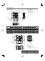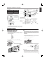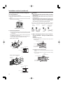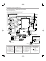
1
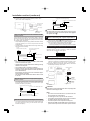
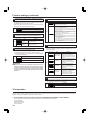
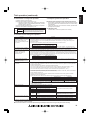
English
Lossnay Energy Recovery Ventilator
Models:
LGH-15RX5-E,
LGH-50RX5-E,
LGH-100RX5-E,
LGH-25RX5-E,
LGH-65RX5-E,
LGH-150RX5-E,
LGH-35RX5-E
LGH-80RX5-E
LGH-200RX5-E
Installation Instructions
Models LGH-15RX5-E to LGH-100RX5-E
(For use by dealer/contractor)
Models LGH-150RX5-E and LGH-200RX5-E
Contents
Safety precautions ............................................. 1
Outline drawings ................................................ 2
Standard installation examples .......................... 3
Installation method ............................................. 3
Function settings .............................................. 10
Trial operation .................................................. 12
This product needs to be installed properly in order to ensure maximum functionality as well as safety.
Please make sure to read this installation manual before starting the installation.
Installation must be performed by a dealer or installation contractor. Please note that improper installation may cause malfunction or accident.
Separate booklet “Operating Instructions” is provided for the customer. The booklet and this manual must be handed over to the customer after completing the installation.
Safety precautions
The following signs indicate that death or serious injury may be caused by failure to heed the precautions described below.
WARNING
Do not
disassemble
Prohibition of use in
bath or shower room
Do not modify or disassemble.
(It could cause fire, electric shock or injury.)
The Lossnay unit and remote controller should not be installed
where it is highly humid, like a bathroom, or other wet place.
(It could cause electric shock or power leakage.)
The instructions
given must be
followed.
Connect the product properly to ground.
(Malfunctioning or power leaks can cause electrical shock.)
Connect the
grounding wire.
CAUTION
Do not place a burning appliance in a place where it is exposed
directly to the air from the Lossnay unit.
(It could cause an accident as a result of incomplete combustion.)
Do not use at a place where it is exposed to high temperatures
(40˚C or higher), naked flames, or in environment with
combustible fumes. (It could cause fire.)
Prohibited
Do not use in an environment such as a chemical factory, where
hazardous gases such as acidic gases, alkaline gases, organic
solvent fumes, paint fumes, or gases containing corrosive
components are generated. (It could malfunction.)
The instructions
given must be
followed.
Do not install this product in a place where it is exposed to
ultraviolet light. (UV may damage covering insulation.)
Use the specified power supply and voltage. (Use of incorrect power supply
or voltage could cause fire or electric shock.)
Select a place with sufficient strength and install the main unit securely.
(It could cause injury if it falls.)
Wiring work must be performed by qualified professionals, and be
implemented safely and securely in accordance with the engineering
standards and the extension wiring rules for electrical equipment.
(Poor connection or improper wiring work could cause electric shock or fire.)
Install a power supply isolator at the power supply side as per local electrical regulations.
All supply circuits must be disconnected before obtaining access to the terminal devices.
Use the specified cable size and connect the cables securely to prevent disconnection
when they are pulled. (If there is a defect in the connection, there is a possibility of fire.)
Select an adequate place for the opening to introduce outdoor air, where it will
not intake the exhaust fumes like combustion gas, or others, and there is no risk
of blockage. (Shortage of fresh air could put the room in a state of oxygen deficiency.)
A duct made of steel must be installed with care not to be connected
electrically with metals such as metal , wire , stainless steel plate, or others.
(It could cause fire when power leakage occurs.)
Put on gloves during installation. (It could cause injury.)
Make sure the power supply isolator is turned off on the power
distribution panel when Lossnay is not used for a long period of
time after the installation. (It could cause electric shock, power
leakage, or fire as a result of deteriorated insulation.)
Always use the specified suspension bolts, nuts and washers or
correctly rated wire / chain hangers. (Use of hardware with insufficient
strength could result in the product dropping.)
The outside ducts must be tilted at a gradient (1/30 or more) down
toward the outdoor louvres from Lossnay, and properly insulated.
(The entry of rain water may cause power leakage, fire, or damage to household property.)
The control box cover must be closed after the installation. (Dust
or humidity may cause power leakage or fire.)
When connecting external devices (electrically operated damper,
lamp, monitoring unit, etc.) using output signals of the Lossnay
unit, make sure to install safety equipment for the external devices.
(It could cause fire, damage, etc. without safety equipment.)
CAUTION
● When using the product where it is exposed to high temperatures and humidity (40˚C or
higher, RH 80% or higher), or where fog occurs frequently, moisture is likely to condense
in the core, and may result in condensation build up in the unit. The product should not
be used under such conditions.
● Outdoor air may enter the Lossnay owing to the pressure difference between indoor
and outdoor or external winds even when the product is not operated. It is recommended
to install an Electrically operated damper to block the outdoor air.
● In a cold weather area, an area with strong external winds or where fog occurs frequently,
cold outdoor air, external winds or fog may be introduced into the product when its
operation is stopped. It is recommended to install an Electrically operated damper.
● When using the product in an environment where there is a window, or opening near
the outdoor louvre , where insects are likely to gather around the interior or exterior
light , take note that small insects may intrude into the product.
● In a cold weather area, or others, dewing or freezing could occur on the main unit,
where the duct is connected, or other sections, depending on the conditions of outdoor
air and indoor temperature and moisture, even if they are within the range of operating
conditions. Make sure to confirm the operating conditions and other precautions, and
do not use the product if dewing or freezing is anticipated.
*Example of dewing condition – Outdoor air: -5˚C or lower, dew-point temperature at installation place: 10˚C or
higher (When the indoor temperature is 22˚C or higher with the relative humidity higher than 50%, or other)
1
Outline drawings
Accessory parts
LGH-15 to 100 RX5
*LGH-80 and 100RX5 types
Position where duct direction change is possible
(4-15 × 20 oval)
Bypass damper plate
M
Ceiling suspension fixture
D
(4-13 × 20 oval)*
F
•
•
•
L
Air exhaust fan
RA
(return air)
E
B
K
EA (exhaust air outlet)
Power supply
cable opening
20
150~250
More than 600
M
95
SA
(supply air)
OA (outside air intake)
Core, air filter, HighEfficiency filter, fan,
maintenance space
Mounting screws ..................................... x16
Duct connecting flanges ........................... x4
(double flanges at SA and EA sides)
Slim-Lossnay connection cable
(gray: two wires) ....................................... x1
F
N
Air supply fan
Inspection
opening
C
Control box
Maintenance cover
Lossnay core
A
High-Efficiency filter (sold separately) attachment position
J
N
øG
øH
J
Position where duct direction change is possible
Air filters
Unit (mm)
Ceiling suspension
fixture pitch
LGH-15 RX5
Dimensions
A
B
C
780
735
273
D
768
E
782
F
65
LGH-25 RX5
LGH-35 RX5
LGH-50 RX5
LGH-65 RX5
LGH-80 RX5
780
888
888
908
1144
735
874
1016
954
1004
273
315
315
386
399
768
875
875
895
1010
782
921
1063
1001
1036
65
80
65
70
389
150
150
200
200
250
142
142
192
192
242
160
160
208
208
258
LGH-100 RX5
1144
1231
399
1010
1263
389
250
242
258
LGH-150 and 200 RX5
63
64
79
79
79
530
650
745
692
690
102.5
112
135.5
131
157
102
124
124
133
165
30
55
30
–
–
20
29
32
40
53
79
917
157
165
–
59
20
Bypass damper plate
Ceiling suspension fixture (4-15 x 30 oval)
C
270
RA
(return air)
A
B
150~250
27
More than 600
110
SA
(supply air)
270
OA
(outside
air intake)
Core, air filter,
High-Efficiency filter,
fan,
maintenance space
N
30
1010
Air exhaust fan
EA
(exhaust
air outlet)
Weight
(kg)
K
530
Duct pitch
L
M
102.5
102
D
Model
Duct connecting flange
Nominal
G
H
J
diameter
100
97.5
110
103
Inspection
opening
399
798
Air supply fan
Control box
Power supply cable
opening
Maintenance cover
Lossnay cores
44
High-Efficiency filter (sold separately) attachment position
1144
79
ø242
ø258
700
ø242
ø258
Accessory parts
•
•
•
Duct connecting flanges ........................... x4
Mounting screws .................................... x16
Slim-Lossnay connection cable
(gray: two wires) ....................................... x1
Unit (mm)
Air filters
2
Model
LGH-150 RX5
A
1004
B
690
C
690
D
1045
Weight (kg)
105
LGH-200 RX5
1231
917
917
1272
118
Standard installation examples
English
•
* Except the 150 and 200 RX 5.
Duct length
Model
LGH-15 to 65 RX5
LGH-80 and 100 RX5
LGH- 150 and 200 RX5
Distance
1 m or more
2.5 m or more
3 m or more
Return air grille
(not Included)
EA (exhaust air outlet)
Lossnay unit
•
The parts can also be installed upside down.
Remove the maintenance cover, rotate the parts
by 180°, and re-install.
Supply air grille
(not included)
OA (outside air intake)
* It can be installed by inverting the top and the bottom.
Maintenance space
Maintenance
space
OA
(outside
air intake)
EA
(exhaust
air outlet)
After installing the duct
connecting flange, remove
the maintenance cover.
Turn the cover by 180˚,
and then reinstall it.
Inspection
opening
Lossnay
unit
EA
(exhaust
air outlet)
OA
Electrically operated damper
(outside
(Protection against the intrusion of cold air while Lossnay is stopped in winter)
air intake) (To be provided by the customer)
EA
(exhaust
air outlet)
OA
(outside
air intake)
•
Inspection opening
Downward gradient of duct:
1/30 or more (toward wall side)
and provision of distance in table
below (to prevent rain water from
seeping in)
Duct
Deep hood
(to prevent rain water
from seeping in)
Lossnay unit
OA
(outside air intake)
Inspection opening
(450x450 or 600x600 mm)
EA
(exhaust air outlet)
Lossnay unit
Anchor bolt (to be provided by user)
Remote controller
(optional parts)
SA
RA
(supply air) (return air)
Supply air grille
(not included)
Return air grille
(not included)
In a region where there is risk of freezing in winter, it is recommended
to install an Electrically operated damper, or the like, in order to
prevent the intrusion of (cold) outdoor air while Lossnay is stopped.
Installation method
CAUTION
Installing the Lossnay unit
•
Before attaching the duct connecting flanges, check that no
foreign matter (scraps of paper, vinyl, etc.) has found its way
inside to Lossnay unit.
•
Attach the duct connecting flanges with the packing at the SA
and RA sides.
1. Preparing the anchor bolts
Mount the washers (outer diameter of >21 mm for M10, >24 mm for
M12) and nuts onto the pre-recessed anchor bolts (M10 or M12), as
shown in the figure below.
3. Mounting Lossnay unit
Anchor bolt (M10 or M12)
(1) Hang the ceiling suspension fixtures on the anchor bolts and
adjust in such a way that Lossnay unit is level.
(2) Tighten up securely using double nuts.
Nut
Washer
Nut
Models LGH-15 to 100 RX5
2. Attaching the duct connecting flanges
Anchor bolt
Ceiling suspension fixture
Use the supplied screws to secure the duct connecting flanges to
the Lossnay unit.
Models LGH-15 to 100 RX5
Mounting
screw
Models LGH-150 and 200 RX5
Washer
Models LGH-150 and 200 RX5
Nut
Mounting screw
(Accessory parts)
Anchor bolt
(M10 or M12)
Nut
Washer
Ceiling suspension fixture
Washer
Duct connecting flange
(Accessory parts)
CAUTION
• When suspending Lossnay unit from the ceiling, do not handle
it in such a way that force will be applied to the control box.
Duct connecting flange
(Accessory parts)
• Install the anchor bolts to ensure the product's weight or
earthquake load. (Correctly rated wire / chain may also be used)
3
Installation method (continued)
If the suspension bolts are short, change the
mounting hardware.
For the models LGH-80 and 100 RX5
(1) Remove the suspension fixture and mount it to the upper mounting
position.
(2) Replace screws in the holes for the suspension fixture that has been
removed to prevent air leakage.
Suspension fixture
CAUTION
•
Before attaching the ducts, check that no (debris or any other)
foreign matter (scraps of paper, vinyl, etc.) has found its way
inside the ducts.
•
Do not touch the damper plate inside Lossnay unit when connecting the ducts.
•
If it is expected that the ambient temperature around the place
where the Lossnay unit is installed will be high during the
summer air conditioning season, it is recommended that the
indoor ductwork be covered with insulation material.
Do not carry out the following types of duct construction. (Doing so
could cause a drop in the air volume and generate abnormal noises.)
• Extremely
sharp bends
• Multiple bends
• Bends right next to
the outlet
• Extreme reduction in
the diameter of the
connected ducts
Screws
Models LGH-80 and 100 RX5
4. Connecting the ducts
(1) Fasten the duct securely to the duct connecting flange, and wrap
aluminum tape (not included) around the joints so that there is
no air leakage.
(2) Suspend the ducts from the ceiling so that their weight will not
be applied to the Lossnay unit.
(3) The two outdoor ducts must be covered with heat-insulating material in order to prevent condensation from forming.
5. When changing the direction of the out door
side duct (EA/OA)·····Except for LGH-150 and
200 RX5
(1) Removal of flange cover
Unscrewing the flange cover mounting screws (4 pcs), remove
the flange cover.
Models LGH-15 to 100 RX5
Duct
Ceiling suspension fixture
Flange cover
Aluminum tape
Mounting screw
(for flange cover)
Heat-insulating
material
Taping
Lossnay
unit
Outdoor duct
Duct connecting
flange
(2) Installation of duct connecting flange
1. Install the duct connecting flange using attached mounting
screws.
2. Fix the removed flange cover with the removed mounting
screws (4 pcs).
Ceiling
suspension fixture
Models LGH-150 and 200 RX5
Duct connection flange
Taping
Duct
Heat-insulating
material
Mounting screw
(Accessory parts)
Duct connecting flange
Aluminum tape
Heat-insulating
material
Lossnay
unit
Outdoor duct
Duct connecting flange
4
Installation method (continued)
English
Electrical installation
With this product, the wiring installation method will vary according to the design of the system.
Perform electrical installation to meet local electrical regulations.
* Always use double insulated PVC cable for the transmission cables.
* Wiring work must be performed by qualified professionals.
* All supply circuits must be disconnected before obtaining access to the terminal devices.
Names of components in control box
LGH-15 to 100 RX5
TM1
LED1
LED4
LED2
SW1
TM4
SW2, SW5
TB5
SA1, SA2
TM2
TM3
Wire connection diagram
* Connect the wires shown as thick lines.
* Be sure to connect the ground wire.
M1:
* A power supply isolator must be installed when wiring power supply to unit. M2:
* Always use a single pole isolator for the main switch power connection.
C:
GREEN/YELLOW
BROWN
POWER SUPPLY
220-240V~50Hz
RED
Isolator
TM1
TAB3
BLUE
BLACK
GREY
YELLOW
M2
TAB5
TAB1
TAB2
CN10
SUPPLY
FAN MOTOR
L
N
N
PE
BROWN
C
L
*1
BLUE
CN1
RED
TR
ORANGE
WHITE
BLUE
M1
CN9
YELLOW
CN7
C
EXHAUST
FAN MOTOR
CN16
*1
GM
RED
LS
CN32
TH1(OA)
BROWN
ORANGE
ORANGE
ORANGE
ORANGE
SW2
CN5
SW1
SW5
TH2(RA)
CN16(Uncharged a-contact)
CN2
BROWN
CN6
ORANGE
ORANGE
TM4
10
SA1 SA2
X10
HI
RED
ORANGE
EXTRA-LO
YELLOW
BY-PASS
GREEN
MAX 240 VAC 1A
24 VDC 1A
9
BROWN
LO
Operation or Delay1
monitor output
X11
TM3
6
7
1
TM2
8
1
TB5
2
3
A
B
S
2nd remote controller (Max. 2 remote controllers installable)
2nd Lossnay unit (Up to max. 15 units)
Transmission
cable (non-polar)
TM4
2
Sheilded Wire
Bypass or Delay2
12V or 24V DC
M-NET-transmission
monitor output 67 Mr.Slim
cable
Malfunction monitor (non-polar)
MELANS
output 78
External control input
MAX 240 VAC 1A
*1 LGH-100RX5 has 2 capacitors
1
3
24 VDC 1A
per mortor as following drawing.
MIN 220 VAC 100mA
5 VDC 100mA Uncharged a-contact
M
C
1
Connector
(Transformer secondary)
CN5: Connector (Thermistor)
CN6: Connector (Microswitch)
CN7: Connector
(Motor for bypass operation)
TAB3: Tab connector (Fan motor)
TAB5: Tab connector (Fan motor)
CN9: Connector (Fan motor)
CN10: Connector (Fan motor)
CN16: Connector (High/Low/Extra
Low/BY-PASS switch)
CN32: Connector
(Remote control selection)
SA1: Address setting rotary switch
(10 digit)
SA2: Address setting rotary switch
(1 digit)
LED1: Inspection indicator lamp
LED2: Inspection indicator lamp
LED4: Power supply indicator lamp
SYMBOL
: Terminal block
: Connector
: Board insertion connector
or fastening connector of
control board.
B
*2
Optional Remote Controller
(PZ-60DR-E)
2nd remote controller
(Max. 2 remote controllers
installable)
TB5 M-NET
A
M-NET
Transmission
cable
CN2:
* When the optional Remote Controller
PZ-60DR-E is used as the M-NET System,
connect it to 1, 2 of TM4 terminal block, and
connect M-NET transmission wire to A, B
on TB5 terminal block.
MIN 220 VAC 100mA
5 VDC 100mA
PZ60DR-E
2
X12
Definition of symbols
Motor for exhaust fan
Motor for supply fan
Capacitor
GM:
Motor for Bypass movement
LS:
Microswitch
TH1: Thermistor for outside air
TH2: Thermistor for return air
SW1: Switch (Main/sub change)
SW2,5: Switch (Function selection)
TM1: Terminal block (Power supply)
TM2: Terminal block
(External control input)
TM3: Terminal block
(Monitor output)
TM4: Terminal block
(Transmission cable and
monitor output)
TB5: Terminal block
(M-NET Transmission cable)
TAB1,TAB2:Connector (Power supply)
TR:
Control circuit transformer
X10: Relay contact
X11: Relay contact
X12: Relay contact
CN1: Connector
(Transformer primary)
S
Shielded wire
C
*2 PZ-41SLB-E and PZ-52SF-E
cannot be used when using
PZ-60DR-E.
2nd or later main units
5
Installation method (continued)
Wire connection diagram ----- Models LGH-150 and 200 RX5
* Connect the wires shown as thick lines.
* Be sure to connect the ground wire.
* A power supply isolator must be installed when wiring power supply to unit.
* Always use a single pole isolator for the main switch power connection.
GREEN/YELLOW
POWER SUPPLY
220-240V 50Hz
TM1
BROWN
RED
BROWN
BLACK
GREY
YELLOW
M2
x103
x103
x102
x102
C
SUPPLY
FAN MOTOR
TAB3 TAB5
*1
BLACK
GREY
YELLOW
TAB1
TAB2
CN10
BLUE
PE
TR1
BLUE
RED
x203
x203
x202
C
*1
x202
ORANGE
BLUE
WHITE
WHITE
CN7
RED
x201
x201
BROWN
BLACK
GREY
YELLOW
CN32
CN16
ORANGE
CN5
ORANGE
ORANGE
ORANGE
RED
GM MG
TR3
BLACK
X12
C
6
SW5
HI
RED
LO
ORANGE
YELLOW
GREEN
BY-PASS
TM4
10
X10
9
X11
2
TM2
7
8
CN16(Uncharged a-contact)
BROWN
BROWN
Bypass or Delay2
monitor output 6,7
Malfunction monitor
output 7,8
MAX 240VAC 1A 24VDC 1A
MIN 220VAC 100mA 5VDC 100mA
LS
GM MG
SA1 SA2
TM3
*1
CN2
BLACK
TH2(RA)
ORANGE
BLUE
WHITE
SW1
SW2
TH1(OA)
C
EXHAUST
FAN MOTOR
LS
BLACK
TR2
BROWN
*1
M1
BLACK
RED
CN9
WHITE
SUPPLY
FAN MOTOR
N
CN1
ORANGE
BLUE
WHITE
M2
N
BROWN
RED
EXHAUST
FAN MOTOR
L
x101
x101
M1
Isolator
L
1
1
TB5
2
3
12V or 24V DC
Mr.Slim
(non-polar)
A
B
MELANS
S
Sheilded Wire
M-NET
transmission
cable
Operation or Delay1
monitor output
MAX 240VAC 2A MIN 220VAC 100mA
24VDC 2A
5VDC 100mA
PZ60DR-E
2nd remote controller (Max. 2 remote controllers installable)
2nd lossnay unit (Up to max 15 units)
Transmission
cable
(non-polar)
* When the optional Remote Controller
PZ-60DR-E is used as the M-NET System,
connect it to 1, 2 of TM4 terminal block,
and connect M-NET transmission wire to A,
B on TB5 terminal block.
TM4
*2
2
Optional Remote Controller
(PZ-60DR-E)
1
External control input
1
3
Uncharged a-contact
*1 LGH-200RX5 has 2 capacitors per mortor as following drawing.
2nd remote controller
(Max. 2 remote controllers
installable)
M
C
TB5 M-NET
C
A
M-NET
Transmission cable
B
S
Shielded wire
*2 PZ-41SLB-E and PZ-52SF-E
cannot be used when using
PZ-60DR-E.
2nd or later main units
Definition of symbols
M1 :
M2 :
C :
GM :
LS :
TH1:
TH2:
SW1:
SW2,5:
TM1:
TM2:
TM3:
6
Motor for exhaust fan
Motor for supply fan
Capacitor
Motor for Bypass movement
Microswitch
Thermistor for outside air
Thermistor for return air
Switch(Main/sub change)
Switch(Function selection)
Terminal block(Power supply)
Terminal block
(External control input)
Terminal block(Monitor output)
TM4:
Terminal block
(Transmission cable and monitor output)
TB5:
Terminal block
(M-NET Transmission cable)
TAB1,TAB2:
Connector(Power supply)
TR1:
Control circuit transformer
TR2,TR3:
Bypass movement transformer
X10,X11,X12 :
Relay contact
X101,X102,X103:
Relay Supply fan speed control
X201,X202,X203 :
Relay Exhaust fan speed control
CN1:
Connector(Transformer primary)
CN2:
Connector(Transformer secondary)
CN5:
Connector(Thermistor)
CN7:
Connector(Motor for Bypass
operation)
TAB3: Tab connector(Fan motor)
TAB5: Tab connector(Fan motor)
CN9:
Connector(Fan motor)
CN10: Connector(Fan motor)
CN16: Connector(High/Low/
BY-PASS switch)
CN32:
Connector
(Remote control selection)
SA1:
Address setting rotary switch
(10 digit)
SA2:
Address setting rotary switch
( 1 digit)
SYMBOL
: Terminal block
: Connector
: Board insertion connector
or fastening connector of
control board.
Installation method (continued)
1. Remove the screws and the control box cover
LGH-15 to 100 RX5
LGH-150 and 200 RX5
Screw
Control box cover
Control box cover
Control box cover
The following system configuration can
be created. Connect the necessary parts.
1 When connecting with remote controller (PZ-60DR-E, PZ-41SLB-E).
2 When interlocked with indoor unit of air conditioner or other
external device including other manufactures.
3 When interlocking with a pulse output device.
4 When operating multiple Lossnay units.
5 When take malfunction monitor output, or take Bypass
operation monitor output.
6 When connect to an Electrically operated damper, or take
operation monitor output.
7 When switching High / Low / Extra-Low speed externally (when
CO2 sensor or other device is connected).
8 When switching Bypass externally.
9 When using the remote/local switching and the ON/OFF input (level signal)
0 When connecting to the City Multi, Lossnay remote controller (PZ-52SFE) or Mitsubishi Electric Air-Conditioner Network System (MELANS).
Screw
CAUTION
•
2. Connecting the power supply cable and
transmission cable
Pass the power cable through the bush* and connect to the TM1
terminal block using the round terminals. Connect the ground wire
to the ground terminal and secure tightening the bush. (*: for PG
connector or the like)
1
When connecting with remote controller (PZ-60DR-E, PZ41SLB-E)
*
When controlling Lossnay units with the central control, connect
wires according to 0.
Securely connect the transmission cable (PVC insulated PVC jacketed and either between φ 0.65 and φ 1.2, or between 0.3 mm2 and
1.25 mm2 in cross section) from the remote controller to 1 and 2 of
the input terminal block (TM4). (No polarity)
• If there are two remote controllers, connect them in the same way.
LGH-15 to 100 RX5
Power supply cable
When connecting external devices (electrically operated damper,
lamp, monitoring unit, etc.) using output signals of the Lossnay
unit, make sure to install safety equipment for the external devices.
(It could cause fire, damage, etc. without safety equipment.)
PG connector
Power supply cable
Note
TM1
Cord clip
•
Don’t tighten screws of terminal block with a torque larger
than 0.5 Nm. It could damage the PCB.
•
Number of transmission wires which can be connected to
single input terminal is up to 4 wires for ø0.65 PVC wire or
0.3 mm2 stranded wire. It is up to 2 wires for any other wires.
•
PZ-41SLB-E cannot be used when MELANS centralized
control of the Lossnay is used.
•
PZ-60DR-E and PZ-41SLB-E cannot be installed simultaneously.
Transmission cable
Ground wire
Bush
Insert the cutting
LGH-150 and 200 RX5
Bush
Lossnay
Cord clips
Up to two remote controllers
(PZ-60DR-E or PZ-41SLB-E) can be used.
Power supply
Insert the cutting
PG connector
TM1 Ground wire
Remote controller input terminal
Power supply cable
2
1
CAUTION
•
Always separate the power supply cable and transmission cable by 5 cm or more to prevent malfunctioning of the unit.
•
If the length of the stripped power cables wires is too long, the
conductors may touch and short out.
•
Power supply cable size : 1.5mm2 or more.
TM4
Transmission wires
2
(1) Connect the output signal cable from the external device to the
input terminal block (TM2) of the external controller.
(1) Tighten the ground wire and transmission cables to the terminal
block.
(2) Secure the transmission cables using the cord clips.
Upon completion of the wiring connections, replace the control box cover.
When interlocked with indoor unit of air conditioner or
other external device including other manufactures
CAUTION
•
The connection may vary according to the output signal type
of the external unit.
•
Don’t tighten screws of terminal block with a torque larger than
0.5 Nm. It could damage the PCB.
7
English
Connecting the power supply cable
Installation method (continued)
Lossnay External controller input (TM2)
(2) Confirm that the pulse input switch (SW2-2) is set to “OFF”.
(Set to “OFF” at time of shipment.)
0.5 mm2 to 1 mm2 sheathed PVC cable
12 3
External device
Remote controller
(PZ-60DR-E or
PZ-41SLB-E)
Lossnay
Uncharge a-contact
External
device
Within 500 m
Power supply
CAUTION
Power supply
Operating switch for
external device
When using Mitsubishi Mr. Slim air conditioner with MA
Remote controller
Connect the interlocking cable connector side to CN2L on the circuit
board for the indoor Mr. Slim unit, then connect the lead wire side to
the 1 and 2 of the input terminal block (TM2) for the Lossnay external controller input. (No polarity)
• Always separate the power supply cable and the Slim-Lossnay
connection cable by 5 cm or more to prevent the unit from
malfunctioning.
• The Slim-Lossnay connection cable is 0.25 m long. When wiring,
extend it as far as necessary.
Lossnay
External controller input (TM2)
Slim-Lossnay connection cable
(Enclosed accessory)
123
•
If an optocoupler or any other type of polar coupler is used at
the uncharged a-contact, connect the positive side to 3 and
the negative side to 1 .
3
When interlocking with a pulse output device
(1) Move the pulse input switch [SW2-2] to the ON position.
(Refer to function settings 1 “Settings for pulse input”.)
(2) Connect the pulse output device (i.e., building management system) to the external control input terminal block [TM2].
• A pulse width of at least 200 msec will be needed.
• When using PZ-60DR-E, it can be set also from the remote controller.
Connecting methods vary depending on the types of pulse signal
Refer to Section 2 “When the external device has a charged
operation signal of 12 VDC or 24 VDC” or “When the external
device has an uncharged a-contact signal”.
ON
CN2L
1
White
2
3
4
5
6
7
8
9 10
SW2
ON
OFF
Mr. Slim (Indoor unit)
Red
Printed circuit board
Within 500 m
Note
•
The Lossnay remote controller (PZ-60DR-E, PZ-41SLB-E)
cannot be used with this system.
•
Use MA remote controller of Mr. Slim for switching Lossnay
ON/OFF or the fan speed.
•
The ventilation mode is “automatic ventilation”.
•
The Slim-Lossnay connection cable may be extended to a
maximum length of 500m. (Extension cable specifications
are as detailed below)
Ensure that all connections are secure and that the appropriate insulation is provided.
Use extension cable sheathed PVC cable or cable 0.5 mm2
to 1.0 mm2.
When the external device has a charged operating signal of
12 VDC or 24 VDC
•
Connect the operating signal (wire) from the external device via
the remote output to 1 and 2 on the external control input
terminal block (TM2). (No polarity)
Lossnay External control input (TM2)
123
0.5 mm2 to 1 mm2 sheathed PVC cable
External device
4
When operating multiple Lossnay units
(1) Connect from Lossnay Unit 1 to Lossnay Unit 2, and from Unit 2 to
Unit 3 and so on up to a maximum of 15 units using a transmission
cable (PVC insulated PVC jacketed and either between φ 0.65
and φ 1.2, or between 0.3 mm2 and 1.25 mm2 in cross section).
(2) Change the setting on the main/sub switch (SW1) on the second
and subsequent Lossnay units to “Sub”.
Lossnay
(Main)
Power
supply
Remote controller
(PZ-60DR-E or PZ-41SLB-E)
External
device
Power
supply
Operating switch
for external device
Lossnay (Sub)
Main/Sub selection
switch
(SW1)
Main
Sub
(Factory setting: main)
First Lossnay
TM4
1
2
Power
supply
TM4
1
2
Second
Lossnay
Lossnay (Sub)
Power
supply
MAX 15 units
Connect to
remote
controller
(PZ-60DR-E)
Connect
to third
Lossnay
Transmission cable
CAUTION
Don’t tighten screws of terminal block with a torque larger than
0.5 Nm. It could damage the PCB.
Note
12 or 24 VDC
Overall connection extension length
•
Up to four 0.3 mm2 stranded wires or φ 0.65 PVC wires can
be connected to one input terminal.
•
For other types of wire, up to two can be connected.
•
The operation signal and pulse signal can be connected to
the external device of the main Lossnay only.
(Follow the operation manual for the external equipment.)
When the external device has an uncharged a-contact signal
•
8
Connect the operating signal (wire) from the external device via
the remote output to 1 and 3 on the external control input
terminal block (TM2).
•
Connect the power to each respective Lossnay unit.
•
When the LGH-150RX5 and LGH-200RX5 types are connected, they
operate at low fan speed even if extra low fan speed is selected.
Installation method (continued)
When take Malfunction monitor output, or take Bypass
operation monitor output.
■ To force Extra-Low fan speed externally
CO2 sensor, etc.
(When CO2 decveases: Closed)
Bypass operation indicator
Monitor output terminal
Bypass operation signal
TM3
contactor rating
Max 240 VAC, 1 A
6
24 VDC, 1 A
Min 220 VAC, 100 mA
7
5 VDC, 100 mA
8
Malfunction signal
Power
Supply
Lamp or
monitoring unit
Malfunction indicator
Connect to 6 and 7, or 7 and 8 of the monitor output terminal
block (TM3) with reference to the wire connection diagram.
Note
* Don’t tighten screws of terminal block with a torque larger than
0.5Nm. It could damage the PCB.
Bypass or Delay 2 monitor output with delay function 2 can be possible.
(Refer to function settings C “Setting for TM3 67”)
6
When connect to an Electrically operated damper, or take
Operation monitor output
Connect the power supply cable from the Electrically operated
damper to 9 and 0 of the monitor output terminal block (TM4)
with reference to the wire connection diagram.
Operation monitor output with delay function 1 can be possible.
(Refer to function settings 6 “Setting for TM4 90”)
Remote ON/OFF adaptor
(Optional) PAC-SA88HA-E
SW1
SW1: Low fan speed operation switch
(When closed: For Low fan speed operation)
Not used. Insulate completely.
Max wiring length 10 m
When SW1 is "ON", fan speed of the Lossnay will be set to "ExtraLow" regardless of the remote control setting.
Use this in such a way that it ventilates at High fan speed normally,
and when the external sensor detects that the indoor air
contamination is low, it changes to Extra-Low fan speed operation.
* For the LGH-150RX5 and LGH-200RX5 types, fan speed of the
Lossnay will be “Low”.
8
When switching Bypass externally.
Establish the wire connection by inserting the optional remote ON/OFF
adaptor (PAC-SA88HA-E) in the connector CN16 (Ventilation mode selector).
Remote ON/OFF adaptor
(Optional) PAC-SA88HA-E
Brown 1
Red 2
Contactor rating
Max 240 VAC, 2 A
24 VDC, 2 A
Min 220 VAC, 100 mA
5 VDC, 100 mA
Lamp
Note
* Don’t tighten screws of terminal block with a torque External Signal Response Time
larger than 0.5Nm. It could damage the PCB.
Level Signal
Max. 7 sec.
* Response times to external input signals are
Pulse Signal Max. 200 msec
as shown in the following table.
When switching High/Low/Extra-Low fan speed externally
(when CO2 sensor or other equipment is connected)
Using marketed CO2 sensor, etc., make connection by inserting the
optional remote ON/OFF adaptor (PAC-SA88HA-E) in the connector
CN16 (High/Low selector) as shown by the figure.
SW1: Bypass ventilation operation switch
(When closed: For Bypass ventilation operation)
Orange 3
Yellow 4
Green 5
The remoto controller (PZ-41SLB-E) cannot be used.
Insert the optional remote ON/OFF adaptor (PAC-SE55RA-E) in
CN32 on the Lossnay control PCB.
Fan speed/
Ventilation
mode selection
When SW1 is "ON", fan speed of the Lossnay will be set to
"High"(Extra-High) regardless of the remote control setting.
Use this in such a way that it ventilates at Low or Extra-Low fan
speed normally, and when the external sensor detects contamination
of indoor air, it changes to High (Extra High) fan speed operation.
■ To force Low fan speed externally
SW1
Remote ON/OFF adaptor
(Optional) PAC-SA88HA-E
Brown 1
Red 2
Orange 3
Yellow 4
Green 5
SW1: Low fan speed operation switch
(When closed: For Low fan speed operation)
Remote control
board
CN16
Not used. Insulate completely.
Max wiring length 10 m
Lossnay
control board
CN16
Fan speed/
Ventilation
mode selection
Not used. Insulate completely.
Max wiring length 10 m
When SW1 is "ON", fan speed of the Lossnay will be set to "Low"
regardless of the remote control setting.
Use this in such a way that it ventilates at High fan speed normally,
and when the external sensor detect that the indoor air contamination
is low, it changes to Low fan speed operation.
Not used. Insulate completely.
Max wiring length 10 m
9
Relay power supply
Remote ON/OFF adaptor
(Optional) PAC-SA88HA-E
Brown 1
Fan speed/
Ventilation
mode selection
With SW1 is “ON”, the ventilation mode of Lossnay is changed to
the Bypass ventilation regardless of the setting on the remote
controller.
* When the outdoor air temperature drops lower than 8˚C, it
changes to the heat exchanger ventilation. (Display of the remote
controller does not change.)
When using the remote/local switching and the ON/OFF
input (level signal)
Lossnay
control board
Red 2
CO2 sensor, etc.
(When CO2 decreases: Closed)
CN16
Yellow 4
Green 5
SW1
■ To force High fan speed externally
SW1: High fan speed operation switch
(When closed: For High fan speed operation)
Lossnay
control board
Orange 3
9
SW1
Fan speed/
Ventilation
mode selection
Green 5
0
CO2 sensor, etc.
(When CO2 increases: Closed)
CN16
Yellow 4
Monitor output
terminal (TM4)
7
Lossnay
control board
Brown 1
Red 2
Orange 3
Power Supply
Electrically
operated
damper
English
5
Remote ON/OFF adaptor Lossnay
Relay circuit (Optional) PAC-SE55RA-E control board
Orange 1
CN32
SW2
X
Red 2
Y
Brown 3
X
SW1
Y
Max wiring length 10 m
SW1: When this is ON, Lossnay cannot turn ON/OFF by the Remote
Controller (PZ-60DR-E, PZ-52SF-E).
SW2: When SW1 is ON, Lossnay can be turned ON by setting SW2
at ON or turned OFF by setting SW2 at OFF.
SW1: Remote/local selector switch
SW2: ON/OFF switch
X, Y : Relay (Contactor rating DC 1 mA)
10
*
When connecting to the City Multi, Lossnay remote controller (PZ-52SF-E)
or Mitsubishi Electric Air-Conditioner Network System (MELANS)
If centralized control is performed according the wire connection
shown in this section, the remote controller (PZ-41SLB-E) cannot be used.
M-NET transmission cable input terminal block
A
TB5
B S
Shielded wire
M-NET transmission cable
9
Installation method (continued)
• One shielded wire is connected to TB5 S on the PCB on terminal.
Address setting is required. (Refer to function setting section.)
M-NET transmission cable: Connect any of the City Multi indoor
unit, or Mitsubishi Electric Air-Conditioner Network System (MELANS) - to
the Lossnay.
• Connecting positions are different for the Remote Controller PZ60DR-E and PZ-52SF-E.
PZ-60DR-E:
Connect to TM4 1, 2 on the PCB. (See Section 1 “When
connecting with Remote Controller (PZ-60DR-E)”.)
PZ-52SF-E:
Connect to TB5 A, B on the same terminal block as for the
M-NET transmission wires.
• Securely connect the M-NET transmission wires to TB5 AB.
(No-Polar)
Type: (Shielded wire, CVVS/CPEVS)
Wire diameter: 1.25 mm2 to 2.0 mm2
When interlocking with Mitsubishi Free Plan air conditioner
•
Incase of PZ-60DR-E
Air
conditioner
MA remote
controller
•
•
Always use shielded wires only for the M-NET transmission
wires, and finish the shield properly.
M-NET transmission cable
Incase of PZ-52SF-E
Air
conditioner
Air
conditioner
MA remote
controller
Lossnay
M-NET transmission cable
PZ-52SF-E
When connecting to PZ-60DR-E and MELANS
•
Don’t tighten screws on the terminal block with a torque larger
than 0.5 Nm. It may damage the PCB.
Lossnay
PZ-60DR-E
CAUTION
•
Air
conditioner
Connect the power feeding unit.
(Optional)
Power
supply unit
MELANS
Lossnay
M-NET transmission cable
*
PZ-60DR-E
Limit the total length of transmission wires no longer than 500 m.
Limit the wiring length between Lossnay and the power supply
unit (Optional) or the outdoor unit no longer than 200 m.
Function settings
(SW2)
Address setting is requiered when connecting to City Multi, Lossnay
remote controller (PZ-52SF-E) and MELANS.
Trial operation
Pulse input setting *
Power supply/exhaust when operation starts *
SA fan fixed at Low speed *
EA fan fixed at Low speed *
Power supply ON/OFF *
Bypass ventilation priority at Automatic mode *
Setting for TM4 90 output
Supply Extra High/High *
Exhaust Extra High/High *
1
2
Setting the address
3
4
Use the following procedure when setting the address for dedicated
Lossnay.
(The method in determining the addresses will depend on the existing
system. Refer to the appropriate technical documents for details.)
(1) Remove the control box cover.
(2) Use a flatblade screwdriver to turn the address setting switch on the
circuit board.
• SA1 indicates the 10 digit and SA2 indicates the 1 digit.
• The factory setting is "00"
5
6
7
8
9
10
(SW5)
1
2
3
4
SA1
SA2
5
6
7
10 digit
1 digit
8
*
When the address number has been changed, the data in the
memory is automatically reset.
Changing the function selection switches
(SW-2 and 5)
Set the selection switches (SW-2 and 5) to perform the appropriate
function.
* The function marked (*) above can be set also from the remote
controller (PZ-60DR-E). If the function is switched later using the
remote controller, it operates according to the setting on the remote
controller.
10
10
1
2
3
4
5
6
7
8
9
0
A
B
C
D
E
Exhaust fan stop during defrosting *
Exhaust fan at Low speed at outdoor air lower than -15˚C *
Auto restoration after power failure *
Filter maintenance indication setting *
Setting for TM3 67 output
} Interlock mode setting *
Exhaust fan stop at outdoor air lower than -15˚C *
Not used OFF: LGH-15 to 100RX5
ON : LGH-150 and 200RX5
Settings for pulse input
Switching to power supply/exhaust when operation starts
Switching to the multi ventilation mode
Power supply ON/OFF function (cannot be set when PZ-41SLB-E is used)
Bypass automatic ventilation priority setting *
Setting for TM4 90 output
Extra High/High switch setting
Set for delay operation at heating or cooling start-up
Operation output monitor
Exhaust fan stop during defrosting, exhaust fan Low speed operation at outdoor air lower than -15˚C
Settings for automatic recovery following power supply interruption
(cannot be set when PZ-41SLB-E is used)
Settings for filter cleaning (cannot be set when PZ-41SLB-E is used)
Setting for TM3 67 output
Settings for interlock mode
Exhaust fan stop at outdoor air lower than -15˚C *
9
Address setting switch
Delay setting *
Operation monitor output *
Function settings (continued)
5
Settings for pulse input
Set as shown when connecting the pulse signal equipment from a
building maintenance system to an external input.
OFF
SW2
ON
Mode
2
No pulse input (factory setting)
2
Pulse input
Bypass automatic ventilation priority setting
Two thermistors in the Lossnay unit detect the indoor (RA) and
outdoor (OA) air temperatures and automatically select the
“Lossnay ventilation” or “Bypass ventilation”. With this mode,
however, priority is given to the “Bypass ventilation”.
* This setting reflects to the night purge operation condition.
OFF
2
Switching to power supply/exhaust when operation starts
This sets the fan to run forcibly for 30 minutes when operation starts
to ventilate the indoor area. After 30 minutes, the system switches
to enable fan speed adjustment from the remote controller. Use this
setting if the indoor air is contaminated at night when the system is
shut down and you desire to ventilate the indoor area quickly when
operation is started in the morning.
OFF
SW2
3
ON
Normal (factory setting)
3
Runs the fan forcibly for 30 minutes when operation
starts.
This sets the ventilation system to in the case that ventilation balance
in accordance with the use environment and installation location is
selected. There are four possible setting modes.
Mode
Operation
4
5
Power Ventilation
Normal (factory setting)
4
5
Power Supply
The fan speed alternates between the
High (Extra high) and Low instead of
the remote controller setting.
Runs the exhaust fan (EA) at Low
speed constantly.
Alternates the supply fan (SA) speed
between the High (Extra high) and
Low.
SW2
4
5
4
5
*
Power Exhaust
Runs the supply fan (SA) at Low
speed constantly.
Alternates the exhaust fan (EA)
speed between the High (Extra high)
and Low.
Power Save
Ventilation
Runs the supply fan (SA) and exhaust
fan (EA) at Low speed constantly.
Switches to the Power Save
Ventilation setting regardless of the
remote controller’s High or Low.
When using the Remote Controller (PZ-60DR-E), operation of the
Extra Low fan speed button initiates the Extra Low fan speed
operation both at the supply (SA) and exhaust (EA) sides.
Independent operation of the supply (SA) or exhaust (EA) side is
prohibited when it is set at the Extra Low fan speed.
4
Controls stop and start operation by turning the power supply (220240 V) for the Lossnay on and off.
SW2
ON
Mode
Operation
6
Off
(factory setting)
Stop and start is performed according to
SW5-4 settings when the power is on.
6
On
Operation possible by turning power on
and off.
Setting for TM4 90 output
ON
7
Operation
8
Operation monitor output
Corresponds to operation mode output (TM490)
based on SW5-2 setting. (factory setting)
8
Operation monitor output with delay function 1
Corresponds to operation mode output (TM490)
supply fan with following function.
• Starts the output (TM490) 10 seconds after supply
fan operates.
• Lossnay continues to operate for 3minutes after
stopping the output (TM490)
Caution : Fan may be operating after turn off the
switch of the remote controller.
SW2
Extra High/High switch setting
Select this function when increased air volume is required or when
the duct piping is longer.
OFF
SW2
8
ON
Operation
9
Supply fan (SA) - High fixed (factory setting)
9
Supply fan (SA) - Extra High fixed
10
Exhaust fan (EA) - High fixed (factory setting)
10
Exhaust fan (EA) - Extra High fixed
Set for delay operation at heating or cooling start-up
Delays Lossnay operation for 30 minutes when City Multi or Mr.
Slim starts operating or when a external device starts operating. (If
the PZ-41SLB-E is used, set it at the remote control. )
Power supply ON/OFF function (cannot be set when
PZ-41SLB-E is used)
OFF
7
When outdoor temperature (OA) is 17˚C or higher within
24 hours, then Bypass ventilation starts by the
comparison OA and RA temperature. The lowest RA
temperature of Bypass operation is 19˚C
When the night purge is set by the remote controller PZ60DR-E, night purge operation starts at a temperature
of 17˚C (within 24 hours).
OFF
Switching to the multi ventilation mode
ON
7
SW2
6
Operation
When outdoor temperature (OA) is 28˚C or higher within
24 hours, then Bypass ventilation starts by the
comparison OA and RA temperature. The lowest RA
temperature of Bypass operation is 24˚C (factory setting)
When the night purge is set by the remote controller PZ60DR-E, night purge operation starts at a temperature
of 28˚C (within 24 hours).
Operation
3
OFF
ON
OFF
SW5
9
ON
Mode
1
No operation delay (factory setting)
1
Operation delay of 30 minutes
* This function is invalid with in 2 hours’ restart
Operation output monitor
This setting is available when SW2-8 is OFF.
OFF
ON
Mode
2
Corresponds to operation mode output (TM4 90)
exhaust fan (factory setting)
2
Corresponds to operation mode output (TM4 90)
supply fan
(The operation monitor output is off when the supply
fan is stopped for operation in cold regions or during
the City Multi or Mr. Slim defrost mode.)
SW5
11
English
1
Function settings (continued)
10
Exhaust fan stop during defrosting, exhaust fan Low speed
operation at outdoor air lower than -15˚C
13
Sets the operation of the exhaust fan (when the air supply fan is
stopped) during defrosting of the air conditioner when Mr. Slim or
City Multi indoor unit is connected to a duct.
When the outdoor air is lower than -15˚C, stop the operation of
exhaust fan. (OA stop operation at cold region)
OFF
SW5
ON
Setting for TM3 67 output
OFF
ON
6
Operation monitor output with delay function 2.
Corresponds to operation mode output (TM3 67)
supply fan with following function.
• Start the output (TM3 67) 10 seconds after supply fan
Operation
3
Exhaust fan operation (factory setting)
3
Exhaust fan stop, exhaust fan operation at Low speed at outdoor air lower than -15˚C
operates but also when the thermistor for outside air (TH1)
detect -5˚C or lower.
• Stop the output (TM3 67) ,when thermistor for outside
air (TH1) detects a temperature higher than 15˚C or stop
the supply fan or malfunction of TH1.
• Lossnay continues to operate for 3 minutes, after stopping
the output (TM3 67)
• Error code is shown on the remote controller and stop the
output in case of followings.
1) TH1 detects higher than 15˚C within 15 minutes after
the output starts.
2) TH1 detects -10˚C or lower, 60 minutes after the output starts.
3) TH1 detects continuously 70˚C or higher for more than 1 minute.
Caution: Fan may be operating after turn off the switch of the
remote controller.
SW5
6
11
Settings for automatic recovery following power supply
interruption (cannot be set when PZ-41SLB-E is used)
Sets for automatic recovery following power supply interruption.
OFF
SW5
ON
Mode
Operation
4
No automatic
recovery
(factory setting)
Stop after recovery
4
Automatic
recovery
Recover to operate in mode used
before power outage
14
12
Settings for filter cleaning
(cannot be set when PZ-41SLB-E is used)
SW5
ON
Unlimited (No “FILTER” display on remote controller)
(factory setting)
5
3000 hours
CAUTION
•
OFF
ON
7
8
Maintenance time
5
Settings for interlock mode
These settings indicate how Lossnay should operate when external
devices are started or stopped. (If the PZ-41SLB-E is used, set it at
the remote control.)
Set the schedule for filter cleaning based on the estimated
concentration of dust in the air. Factory setting is unlimited.
* When using PZ-60DR-E, it is also possible to indicate the cleaning
cycle of filter (3,000 hours).
OFF
Operation
Bypass ventilation operation monitor output.
Corresponds to operation mode output (TM3 67) of
bypass damper. (factory setting)
7
8
Mode
Operation
On/Off interlock
(factory setting)
The Lossnay will start and stop
according to the operation of the
external devices. Subsequent
operation will be possible using the
remote controller for the Lossnay or
MELANS.
On interlock
The Lossnay will operate whenever
external devices are operated.
Lossnay stop operation will be
possible using its remote controller
or MELANS.
Off operation
The Lossnay will stop whenever
external devices are stopped.
Lossnay start operation will be
possible using its remote controller
or MELANS.
External input
given priority
The Lossnay will start and stop
according to the operation of the
external devices. Control via the
Lossnay remote controller or
MELANS will only be possible when
external devices are stopped.
SW5
When the setting for the cumulative operation time of the
Lossnay is exceeded, the filter cleaning display will appear
on the indoor unit remote controller or the Lossnay remote
controller. After cleaning the filter, the filter cleaning display
can be reset. Refer to the operating instructions for the remote
controller.
7
8
7
8
15
Exhaust fan stop at outdoor air lower than -15˚C
Set the exhaust fan operation when the outdoor air is lower than
-15˚C. (Suction stop operation at cold region)
OFF
SW5
ON
Operation
9
Supply fan stop, exhaust fan normal operation (factory setting)
9
Supply fan stop, exhaust fan stop
Trial operation
After the system has been installed and before the ceiling panel is installed, make sure that wires are properly connected, then test the system’s
operation, referring to the operation manual for the remote controller.
1. Trial operation using the remote controllers (PZ-60DR-E, PZ-41SLB-E and PZ-52SF-E)
Follow the procedure shown in the operation manual for the remote controller the functions below.
(1) Start operation.
(2) Fan speed selection.
(3) Function selection.
(4) Stop operation.
12
Trial operation (continued)
(1) Supply power to the Lossnay unit.
(2) Turn the trial operation switch (SW2-1) “On.”
• Operation will start with the “High” setting and with Bypass
ventilation operating. (This will take approximately 1 minute
after the power is turned on.)
(3) Confirm that the Bypass damper plate in the Lossnay unit is operated.
(4) Turn the trial operation switch (SW2-1) “Off.”
OFF
SW2
1
ON
Operation
Power will be supplied to the motor for the Lossnay fan and
operation will be performed at the “High” setting. Power will be
supplied to the motor for the Lossnay by-pass and operation of
the damper plate will be performed. (Approximately 1 minute)
3. Complete system trial operation
■ Interlock system containing an indoor unit and/or external device
• Use the remote controller for the indoor unit or the operating switches
for the external device and confirm that the indoor unit and Lossnay
are interlocked.
• If delay time has been set, check that the Lossnay operates after
the delay time has passed.
■ If MELANS System
• Use MELANS to confirm the operation of the Lossnay.
4. If trouble occurs during trial operation
Remedy
Symptom
Will not operate even when the
operation switch for the remote
controller (PZ-60DR-E, PZ-41SLB-E)
and/or operation switch for the
Lossnay remote controller (PZ-52SFE) is pressed.
“HO” flashes in remote controller for
Lossnay (PZ-52SF-E).
When using M-NET, the operation
switch of Remote Controller (PZ60DR-E), Lossnay remote
controller (PZ-52SF-E) or
MELANS is dead.
Does not operate even when the
operation switch for remote
controller for Lossnay (PZ-52SF-E)
or MELANS is pressed.
Indoor unit or external device does
not interlock.
• Check the power supply. (The specified power supply is single-phase 220-240V ~ 50Hz.)
• Check for a short circuit or disconnection in the transmission cable. (Check that the voltage between terminals in the
transmission cables is 9 to 15 VDC for the PZ-60DR-E or PZ-41SLB-E and 20 to 30 VDC for the PZ-52SF-E.)
• Check that the there is 5 cm or more separating the transmission cable from the power supply cable and any other
transmission cables.
• Run the Lossnay independently using the trial operation switch (SW2-1) and check if it runs.
•
•
•
•
•
•
•
Lossnay runs
→ Check the signal lines
Lossnay doesn’t run
→ Check the power supply
Check if there are three or more remote controller connected (PZ-60DR-E or PZ-41SLB-E). (The maximum is two.)
Perform the registration operation using the remote controller for the Lossnay (PZ-52SF-E) or MELANS. (Refer to the
installation instructions for the remote controller for the Lossnay or MELANS.)
Check the power supply. (Specified power supply: single-phase 220-240V, wire dia. ø1.6, switch capacity
Check if the power supply unit is connected or not, and if the power is supplied or not (For a system with Lossnay only, it is necessary to install the power supply unit.)
Check the transmission wire for short-circuit or broken wire (Check if DC 20 - 30 V is detected between the terminals of transmission wire).
Check if a clearance of 5 cm is secured between the transmission wire and the power cable and other transmission wires.
Run Lossnay independently to see if it operates properly or not.
Lossnay operates
→ Inspect the transmission wire
Lossnay doesn’t operate → Check the power supply
• Check whether or not there is a power supply unit and that the power has been turned on. (On systems with only a
Lossnay, a power supply unit is required.)
• Check if the pulse input switch (SW2-2) is off. (Can be set from PZ-60DR-E)
• Check the overall cable length between the indoor unit or external device and Lossnay. (Refer to technical publications
or other such documents.)
• Check the connections at the external control input terminal block (TM2).
In the case of voltage charged 12 or 24 VDC output device: Connect to external control input terminals 1 and 2.
In the case of uncharged a-contact output device: Connect to external control input terminals 1 and 3.
In the case of Mr. Slim (A control or K control): Connect to external control input terminals 1 and 2.
• Perform the registration operation using the remote control for the air conditioner or MELANS. (Refer to the installation
instructions for the remote controller for the indoor unit or MELANS.)
• Check if the delay has been set.
• Check the overall length of the transmission cable between the external device and Lossnay. (Refer to technical
publications or other such documents.)
• Check if the transmission cable from the external device has come off of the external control input terminal.
Operation signal
Stop signal
Charged 12 or 24 VDC output device
12 or 24 VDC
0 VDC
Uncharged a-contact output device
Resistance: 0 Ω
Unlimited resistance Ω
Mr. Slim
2 to 6 VDC (pulse signal)
2 to 6 VDC (pulse signal)
• Check, in the case of multiple units, whether the Main/Sub selection switch on the Lossnay unit which is connected to
the external control input terminal is set on the Master setting, and check whether the Main/Sub selection switch on other
Lossnay units are set to Sub.
Lossnay does not stop.
The inspection indicator lamp (LED
1 Green) in the control box flashes.
• Check that the trial operation switch (SW2-1) is set to off.
2 flashes
3 flashes
Fault on Lossnay circuit
Fault on Damper devices
4 flashes
5 flashes
Fault on Lossnay thermostat (OA side)
Fault on Lossnay thermostat (RA side)
8 flashes
Improper OA temperature (outside the range)
On
The inspection indicator lamp (LED
2 Red ) in the control box flashes.
1 to 8
flashes
On
Turn the power off and consult your dealer.
Operating
Unless the Remote Controller (PZ-60DR-E) or remote
controller switch (PZ-41SLB-E, etc) is used, the lamp
extinguishes (operation stops) 30 minutes later.
Error in M-NET communication
Turn off the power and immediately contact your
dealer.
Registration operation has not been performed.
Use the controller to perform the registration.
■ When an inspection number blinks on the remote controller, follow the procedures shown in the installation and operating manuals
provided with the remote controller.
■ If the remote controller is not used, operate after approximately 45 seconds of turning on the power for the Lossnay.
13
English
2. Stand-alone Lossnay trial operation