1
Orion Weather Station
1
___________________________________________________________________
Orion Weather Station™
User Manual
Version 2.00
Serial Number: ___________________
Date Purchased: __________________
All specifications subject to change without notice.
Printed in U. S. A.
Columbia Weather Systems, Inc.
2
Orion Weather Station
____________________________________________________________________
© Copyright 2005 - 2010 Columbia Weather Systems, Inc. All Rights
Reserved.
Proprietary Notice: Orion, Orion LX, Capricorn 2000, Capricorn 2000MP
and Capricorn 2000EX are trademarks of Columbia Weather Systems,
Inc. The information and drawings contained herein are the sole property
of Columbia Weather Systems, Inc. Use of this publication is reserved
exclusively for customers of Columbia Weather Systems, Inc. and their
personnel. Reproduction of this material is forbidden without the express
written consent of Columbia Weather Systems, Inc.
Parts of the Orion Weather Station™ user manual were adapted from the
Weather Transmitter WXT520 User’s Guide with permission from Vaisala
Oyj.
WINDCAP®, RAINCAP®, HUMICAP®, BAROCAP® and
THERMOCAP® are registered trademarks of Vaisala.
Orion Weather Station
3
___________________________________________________________________
Welcome!
Congratulations on your purchase of an Orion Weather Station.
Please read this manual completely prior to installation.
Columbia Weather Systems, Inc.
4
Orion Weather Station
____________________________________________________________________
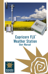
Orion Weather Station
5
___________________________________________________________________
Important Notice: Shipping
Damage
BEFORE YOU READ ANY FURTHER, please inspect all system
components for obvious shipping damage. The Orion is a high
precision instrument and can be damaged by rough handling. Your unit
was packaged to minimize the possibility of damage in transit. Please
save the shipping container for any future shipment of your Orion sensor.
In the event your order arrives in damaged condition, it is important that
the following steps be taken immediately. The title transfers automatically
to you, the customer, once the material is entrusted to the transport
company.
NOTE: DO NOT RETURN THE INSTRUMENT TO COLUMBIA
WEATHER SYSTEMS until the following steps are completed. Failure to
follow this request will jeopardize your claim.
1. Open the container and inspect the contents. Do not throw away
the container or any damaged parts. Try to keep items in the
same condition as originally received.
2. Notify the transport company immediately.
3. Request the transport company’s representative inspect the
shipment personally.
4. After inspection, request a Return Materials Authorization (RMA)
from Columbia Weather Systems by calling (503) 629-0887.
5. Return approved items to us at the following address:
Columbia Weather Systems, Inc.
2240 NE Griffin Oaks Street, Suite 100
Hillsboro, OR 97124
6. After a repair evaluation, an estimate of the cost of repair will be
sent to you.
Columbia Weather Systems, Inc.
6
Orion Weather Station
____________________________________________________________________
ESD Protection
Electrostatic Discharge (ESD) can cause immediate or latent damage to
electronic circuits. Vaisala products are adequately protected against
ESD for their intended use. However, it is possible to damage the
product by delivering electrostatic discharges when touching, removing,
or inserting any objects inside the equipment housing.
To avoid delivering high static voltages yourself:
1. Handle ESD sensitive components on a properly grounded and
protected ESD workbench. When this is not possible, ground
yourself with a wrist strap and a resistive connection cord to the
equipment chassis before touching the boards. When neither of
the above is possible, at least touch a conductive part of the
equipment chassis with your other hand before touching the
boards.
2. Always hold the boards by the edges and avoid touching the
component contacts.
Orion Weather Station
7
___________________________________________________________________
Table of Contents
WELCOME! ..................................................................................3
IMPORTANT NOTICE: SHIPPING DAMAGE .......................5
ESD PROTECTION ............................................................................................. 6
SECTION 1: INTRODUCTION ................................................11
THE ORION WEATHER STATION ..................................................................... 11
SPECIFICATIONS .............................................................................................. 12
Operating Conditions................................................................................. 12
Wind Speed ................................................................................................ 12
Wind Direction........................................................................................... 12
Relative Humidity....................................................................................... 12
Temperature............................................................................................... 13
Barometric Pressure .................................................................................. 13
Precipitation .............................................................................................. 13
Input Voltage.............................................................................................. 14
Heating Power Source ............................................................................... 14
Sensor Housing .......................................................................................... 14
PRINCIPLES OF MEASUREMENTS ..................................................................... 15
Wind Measurement .................................................................................... 15
Barometric Pressure, Temperature, and Relative Humidity (PTU) Module
................................................................................................................... 16
Rainfall Measurement................................................................................ 17
SECTION 2: PHYSICAL DESCRIPTION...............................19
ORION SENSOR TRANSMITTER ........................................................................ 19
Sensor Transmitter Components ................................................................ 19
Mounting Adapter ...................................................................................... 21
Internal Terminal Block............................................................................. 21
Heating (Optional)..................................................................................... 23
Orion Interface Module ............................................................................. 24
SURGE/LIGHTNING PROTECTORS .................................................................... 25
WEATHERMASTER SOFTWARE (OPTIONAL)................................................ 26
WEATHER DISPLAY CONSOLE (OPTIONAL) .................................................... 27
WEATHER MICROSERVER (OPTIONAL)........................................................... 28
SECTION 3: FIXED MOUNT INSTALLATION....................29
FIXED MOUNT SYSTEM CONFIGURATIONS ..................................................... 29
INSTALLATION OVERVIEW.............................................................................. 31
UNPACKING THE UNIT .................................................................................... 31
Installing the Orion Sensor Transmitter .................................................... 33
Site Selection: ............................................................................................ 33
Columbia Weather Systems, Inc.
8
Orion Weather Station
____________________________________________________________________
Installing the Mounting Adapter ................................................................ 33
North Alignment......................................................................................... 34
Installing the Mast ..................................................................................... 35
Location ..................................................................................................... 35
Mounting Method....................................................................................... 35
Routing Cable ............................................................................................ 35
Connecting the Sensor Transmitter to the Interface Module ..................... 37
OPTIONAL SENSOR MOUNTING HARDWARE ................................................... 38
Tripod and Tiedown Kit ............................................................................. 38
Specifications ............................................................................................. 40
Roof Mounting ........................................................................................... 41
Wall Mounting ........................................................................................... 43
SECTION 4: VEHICLE MOUNT INSTALLATION..............45
VEHICLE MOUNT SYSTEM CONFIGURATIONS ................................................. 45
INSTALLATION OVERVIEW.............................................................................. 45
UNPACKING THE UNIT .................................................................................... 46
INSTALLING THE TELESCOPING MAST AND VEHICLE-MOUNT BRACKETS ......... 47
INSTALLING THE VEHICLE MOUNT SENSOR CONNECTOR AND ROUTING CABLE 48
INSTALLING THE INTERFACE MODULE............................................................ 48
CONNECTING THE WEATHER DISPLAY CONSOLE AND COMPUTER ................. 49
INSTALLING THE SENSOR TRANSMITTER AND NORTH ORIENTATION .............. 50
Installing the Mounting Adapter ................................................................ 50
North Alignment......................................................................................... 51
SECTION 5: NOMAD PORTABLE INSTALLATION ..........53
INSTALLATION OVERVIEW.............................................................................. 53
ORION NOMAD SYSTEM CONFIGURATIONS .................................................... 53
UNPACKING THE UNIT .................................................................................... 55
Orion Carrying Case ................................................................................. 57
TRIPOD AND TIEDOWN KIT ............................................................................. 58
Tripod Parts List:....................................................................................... 59
Specifications ............................................................................................. 60
RS-232 Interface Module ........................................................................... 61
Installing the Mounting Adapter ................................................................ 62
SET UP INSTRUCTIONS .................................................................................... 62
Site Selection: ............................................................................................ 62
Mast Set Up and Sensor Alignment: .......................................................... 63
Transportation Case and Sensor Plug-In .................................................. 65
Battery Power System ................................................................................ 65
OPERATION ..................................................................................................... 65
MONITORING .................................................................................................. 66
SECTION 6: ORION SENSOR DATA OUTPUT
DEFINITION ...............................................................................67
Wind data................................................................................................... 67
Orion Weather Station
9
___________________________________________________________________
PTU Data................................................................................................... 68
Precipitation Data: .................................................................................... 68
Supervisory Data: ...................................................................................... 68
CRC-16 Computation................................................................................. 69
Encoding the CRC as ASCII Characters ................................................... 70
SECTION 7: CALIBRATION....................................................71
FACTORY CALIBRATION ................................................................................. 71
TEMPERATURE AND PRESSURE READING ADJUSTMENTS................................ 72
SECTION 8: MAINTENANCE .................................................73
CLEANING....................................................................................................... 73
REPLACING THE PTU MODULE....................................................................... 73
FACTORY CALIBRATION AND REPAIR SERVICE .............................................. 74
SECTION 9: TROUBLESHOOTING.......................................75
SECTION 10: USER SUPPORT INFORMATION .................77
LIMITED WARRANTY ...................................................................................... 77
EXCLUSIONS ............................................................................................ 77
RETURN FOR REPAIR PROCEDURE .................................................................. 78
REFERENCE...............................................................................81
GLOSSARY ...................................................................................................... 81
Aspirating Radiation Shield ....................................................................... 81
Barometric Pressure .................................................................................. 81
Celsius Temperature Scale......................................................................... 81
Dew Point .................................................................................................. 81
Fahrenheit Temperature Scale................................................................... 81
Heat Index.................................................................................................. 81
Relative Humidity....................................................................................... 82
Sea Level Pressure..................................................................................... 82
Wind Chill .................................................................................................. 82
UNIT CONVERSION ......................................................................................... 83
Speed.......................................................................................................... 83
Temperature............................................................................................... 83
Distance ..................................................................................................... 83
Pressure ..................................................................................................... 83
TABLES AND FORMULAS ................................................................................. 84
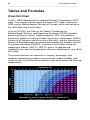
Wind Chill Chart........................................................................................ 84
Wind Chill Equation .................................................................................. 85
Heat Index.................................................................................................. 86
Dew Point .................................................................................................. 87
Columbia Weather Systems, Inc.
10
Orion Weather Station
____________________________________________________________________
Orion Weather Station
11
___________________________________________________________________
SECTION 1: INTRODUCTION
The Orion Weather Station
The Orion weather station provides ultrasonic wind direction and speed
measurements, a highly-accurate impact rain sensor, capacitive relative
humidity, temperature and barometric pressure readings – all in a single
sensor module.
High accuracy and fine resolution make this system ideal for precision
weather monitoring.
Available in three configurations – fixed-mount, vehicle-mount, and the
Orion Nomad™ portable weather station – Orion data can be monitored
with our proprietary Weather Display Console and WeatherMaster™
Software, as well as with third-party software.
The Weather MicroServer is available for Ethernet connectivity,
Modbus/TCP, Modbus RTU and SNMP interface, Weather Underground
and CWOP interface, XML weather data, and FTP.
Columbia Weather Systems, Inc.
12
Orion Weather Station
____________________________________________________________________
Specifications
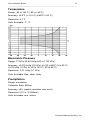
Operating Conditions
Temperature Operation: -52 to +60°C (-6- to +140°F)
Relative humidity: 0 to 100%
Pressure: 600 to 1100 hPa
Wind: 0 to 60 m/s
Wind Speed
Range: 0-135mph (0-60 m/s)
Accuracy: ±0.7 mph (+/-0.3 m/s) or ±3%, whichever is greater for the
measurement range of 0 – 35 m/s
±5% for the measurement range of 36 – 60 m/s
Resolution: 1 mph (1 m/s)
Units Available: knots, mph, km/hr, m/s
Wind Direction
Azimuth: 0-360°
Accuracy: ±3°
Resolution: 1°
Units Available: ° Azimuth
Relative Humidity
Range: 0 - 100%
Accuracy: ±3% (0-90%), 5% (90-100%)
Resolution: 1%
Units Available: %RH
Orion Weather Station
13
___________________________________________________________________
Temperature
Range: -60 to 140°F (-52 to +60°C)
Accuracy: ±0.5°F (+/-0.3°C) at 68°F (+20°C)
Resolution: 0.1°F
Units Available: °F, °C
Barometric Pressure
Range: 17.50 to 32.50 InHg (600 to 1100 hPa)
Accuracy: ±0.015 InHg (0.5 hPa) at +32 to 86°F (0 to 30°C)
±0.03 InHg (1 hPa) at -60 to 140°F (-52 to 60°C)
Resolution: 0.01 InHg (0.1 hPa)
Units Available: Kpa, mbar, InHg
Precipitation
Range: cumulative
Collection Area: 602cm
Accuracy: ±5% (spatial variations may exist)
Resolution 0.01 in. (0.254mm)
Units Available: mm, inches
Columbia Weather Systems, Inc.
14
Orion Weather Station
____________________________________________________________________
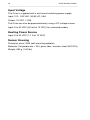
Input Voltage
The Orion is supplied with a wall mount switching power supply
Input: 100 - 240 VAC, 50/60 HZ, 0.6A
Output: 12 VDC, 1.25A
The Orion can also be powered directly using a DC voltage source
Input: 5 to 30 VDC (60 mA at 12 VDC) for unheated models
Heating Power Source
Input: 5 to 30 VDC (1.1 A at 12 VDC)
Sensor Housing
Protection class: IP66 (with mounting adapter)
Materials: Polycarbonate + 20% glass fiber, stainless steel (AISI 316)
Weight: 650 g (1.43 lbs)
Orion Weather Station
15
___________________________________________________________________
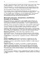
Principles of Measurements
Wind Measurement
Both wind speed and direction are measured using advanced ultrasonic
technology. The sensor utilizes ultrasound to determine horizontal wind
readings. The array of three equally-spaced ultrasonic transducers on a
horizontal plane is an ideal design that ensures accurate wind
measurement from all directions, without blind angles or corrupted
readings.
The wind sensor has no moving parts, which makes it virtually
maintenance free.
Wind speed and wind directions are determined by measuring the time it
takes the ultrasound to travel from each transducer to the other two.
The wind sensor measures the transit time (in both directions) along the
three paths established by the array of transducers. This transit time
depends on the wind speed along the ultrasonic path. For zero wind
speed, both the forward and reverse transit times are the same. With
wind along the sound path, the up-wind direction transit time increases
and the down-wind transit time decreases.
The wind speed is calculated from the measured transit times using the
following formula:
Vw = 0.5 x L x (1/ tf – 1/tr
where:
Vw = Wind speed
L = Distance between the two transducers
tf = Transit time in forward direction
tr = Transit time in reverse direction
Measuring the six transit times allows Vw to be computed for each of the
three ultrasonic paths. The computed wind speeds are independent of
altitude, temperature and humidity, which are cancelled out when the
transit times are measured in both directions, although the individual
transit times depend on these parameters.
Using Vw values of two array paths is enough to compute wind speed
and wind direction. A signal processing technique is used so that wind
speed and wind direction are calculated from the two array paths of best
quality.
The wind speed is represented as a scalar speed in selected units (m/s,
kt, mph, km/h). The wind direction is expressed in degrees (°). The wind
Columbia Weather Systems, Inc.
16
Orion Weather Station
____________________________________________________________________
direction reported indicates the direction that the wind comes from. North
is represented as 0°, east as 90°, south as 180°, and west as 270°.
The wind direction is not calculated when the wind speed drops below
0.05 m/s. In this case, the last calculated direction output remains until
the wind speed increases again to the level of 0.05 m/s.
The average values of wind speed and direction are calculated as a
scalar average of all samples over the selected averaging time (1 ... 900
s). The sample count is based on a 4 Hz sampling rate. The minimum
and maximum values of wind speed and direction represent the
corresponding extremes during the averaging time.
Barometric Pressure, Temperature, and Relative
Humidity (PTU) Module
Barometric pressure, temperature, and humidity measurements are
combined in an advanced sensor module (PTU) utilizing a capacitive
measurement method for each parameter. The PTU module contains
separate sensors for pressure, temperature, and humidity measurement.
The measurement principle of the pressure, temperature, and humidity
sensors is based on an advanced RC oscillator and two reference
capacitors against which the capacitance of the sensors is continuously
measured. The microprocessor of the transmitter performs compensation
for the temperature dependency of the pressure and humidity sensors.
Barometric pressure is measured using a capacitive silicon
BAROCAP® sensor. The sensor has minimal hysteresis and excellent
repeatability, as well as outstanding temperature and long-term stability.
Temperature is measured with a capacitive ceramic THERMOCAP®
sensor.
Relative humidity measurement is based on a capacitive thin film
polymer HUMICAP®180 sensor. The sensor is highly accurate with
negligible hysteresis and excellent long-term stability in a wide range of
environments.
Radiation Shield: This module is mounted in a specially-designed
radiation shield which protects the sensors from both scattered and
direct sunlight and precipitation. The composite material in the plates
offers excellent thermal characteristics and UV stabilized construction.
The white outer surface reflects radiation, while the black inside absorbs
accumulated heat.
The internal sensor module is easily replaceable and readily available as
a spare component. To order a replacement module, please use catalog
no. 9581.
Orion Weather Station
17
___________________________________________________________________
Rainfall Measurement
Rainfall is measured with an impact sensor, which detects the size and
impact of individual rain drops. The signals resulting from the impacts are
proportional to the volume of the drops. Hence, the signal from each
drop can be converted directly to the accumulated rainfall.
This measurement method eliminates flooding and clogging, as well as
wetting and evaporation losses.
The sensor transmitter uses RAINCAP® sensor 2 technology in
precipitation measurement.
The precipitation sensor is comprised of a steel cover and a piezoelectric
sensor mounted on the bottom surface of the cover.
The precipitation sensor detects the impact of individual raindrops. The
signals from the impact are proportional to the volume of the drops.
Advanced noise filtering technique is used to filter out signals originating
from other sources than raindrops.
The measured parameter is accumulated rainfall. Detection of each
individual drop enables computing of rain amount with high resolution.
Columbia Weather Systems, Inc.
18
Orion Weather Station
____________________________________________________________________
Orion Weather Station
19
___________________________________________________________________
SECTION 2: PHYSICAL
DESCRIPTION
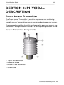
Orion Sensor Transmitter
The Orion Sensor Transmitter is an all-in-one sensor unit containing
ultrasonic wind speed and direction sensor, temperature sensor, relative
humidity sensor, barometric pressure sensor and an impact rain sensor.
The temperature, relative humidity and barometric pressure sensors are
combined in a single module housed in a self-aspirating radiation shield.
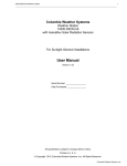
Sensor Transmitter Components
1: Top of the transmitter
2: Radiation Shield
3: Bottom of the transmitter
4: Screw cover
Columbia Weather Systems, Inc.
20
Orion Weather Station
____________________________________________________________________
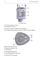
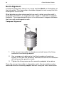
Cut Away View
1: Wind Transducers (3 pcs)
2: Precipitation Sensor
3: Pressure sensor inside the Sensor Module
4: Humidity and temperature sensor inside the Sensor Module
Bottom of the Transmitter
1: Alignment direction sign
2: Service port
3: Watertight cable gland
4: Unused cable gland, covered
5: Optional M12 connector
Orion Weather Station
21
___________________________________________________________________
Mounting Adapter
To facilitate easy installation and north alignment, the Orion Sensor
Transmitter comes standard with a mounting adapter. The mounting
adapter is easily connected to the end of the mast and the sensor
transmitter simply snaps into it. The north alignment needs to be
performed only once.
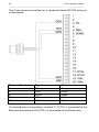
Internal Terminal Block
The sensor transmitter is shipped with a one (1) foot cable terminated by
an 8-pin connector half.
This cable is connected to the sensor transmitter (at the factory) via a
terminal block.
1: Grounding jumper (remove for ship marine applications).
Columbia Weather Systems, Inc.
22
Orion Weather Station
____________________________________________________________________
The Orion sensor transmitter has a standard internal RS-232 wiring as
shown below:
Terminal Number
3
5
6
19
20
Signal
TXRXD
SGND
VINVIN+
Color
Orange
Black
Green
White
Red
For heated sensor transmitters, terminal 17 (HTG-) is connected to the
Blue wire and terminal 18 (HTG+) is connected to the Brown wire.
Orion Weather Station
23
___________________________________________________________________
Heating (Optional)
Heating elements located below the precipitation sensor and inside the
wind transducers keeps the precipitation and wind sensors free from
snow and ice. A heating temperature sensor (Th) underneath the
precipitation sensor controls the heating.
Three fixed temperature limits, namely +3 °C, -2 °C, and -4 °C (+37 °F,
+38 °F, +25 °F) control the heating power as follows:
Th > +3 °C
heating is off
-2 °C < Th < +3 °C
50% heating power
-4 °C < Th < -2 °C
100% heating power
Th < -4 °C
50% heating power
Columbia Weather Systems, Inc.
24
Orion Weather Station
____________________________________________________________________
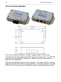
Orion Interface Module
The Orion Interface Module is used to supply power to the sensor
transmitter and to provide two RS-232 communication ports. The RS-232
ports can be connected to computers, display consoles, transceivers,
and other such devices.
The Interface Module has two LED indicators. The green LED is a power
indicator and the red LED is a data indicator. In normal operation, the red
LED will flash every second to indicate a data record being transmitted.
Orion Weather Station
25
___________________________________________________________________
Surge/Lightning Protectors
A nearby lightning strike may induce a high voltage surge which the
internal suppressor of your weather instrument may not be able to
withstand, causing significant damage to the weather station. Protect
your weather station investment with the Orion Surge Protector. This
compact transient overvoltage suppressor is designed for weather
stations in areas with an elevated risk of lightning strikes such as the top
of high buildings, or installations with cable lengths greater than 100 feet.
•
Superior 3-stage surge protection
•
Tolerates up to 10kA surge currents
•
Both differential and common mode protection on each channel
•
Filtering against HF and RF noise
•
Two power channels and two data channels
•
Environmental protection class IP66
Catalog Number: 8355
Includes adjustable mounting kit
Columbia Weather Systems, Inc.
26
Orion Weather Station
____________________________________________________________________
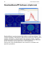
WeatherMaster
Software (Optional)
WeatherMaster is professional grade weather monitoring software. This
software package is designed for specialized markets that require robust
weather calculations, interoperability with computer models, and data
interfaces to other industrial systems. WeatherMaster utilizes Microsoft
Access database for easy data access and manipulation.
Please refer to the WeatherMaster user manual for installation and
operation procedures
Orion Weather Station
27
___________________________________________________________________
Weather Display Console (Optional)
The Weather Display uses “intelligent” touch-screen technology to
display weather information, perform complex computations, and store
relatively large amounts of weather data.
The Weather Display is also available in a 19” rack-mount chassis and a
panel-mount configuration.
Please refer to the Weather Display Console user manual for more
information.
Columbia Weather Systems, Inc.
28
Orion Weather Station
____________________________________________________________________
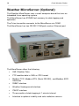
Weather MicroServer (Optional)
The Weather MicroServer uses a small computer board that runs an
imbedded Linux operating system.
The MicroServer has 512MB flash memory for data logging and
operation.
The Orion transmitter connects to the MicroServer via COM1.
The MicroServer has two RS-232 COM ports and an Ethernet port
The MicroServer offers the following:
•
XML Weather Data
•
FTP weather data in XML or CSV format
•
Modbus/TCP, Modbus RTU (Serial RS-232), and Modbus ASCI
interfaces
•
SNMP interface
•
Weather Underground interface
•
CWOP interface
•
Three months of data logging at 1-minute interval
•
Interface to optional visibility and solar radiation sensors
Orion Weather Station
29
___________________________________________________________________
SECTION 3: Fixed Mount
Installation
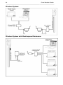
Fixed Mount System Configurations
The Orion Weather Fixed Mount Station can be installed in multiple
configurations depending on communication options, power availability
and viewing options.
Cabled System:
Columbia Weather Systems, Inc.
30
Orion Weather Station
____________________________________________________________________
Wireless System:
Wireless System with Weatherproof Enclosure:
Orion Weather Station
31
___________________________________________________________________
Installation Overview
Unpacking the Unit
Installing Sensor Transmitter
Installing the Interface Module
Connecting the Sensor Transmitter to the Interface Module
Connecting to MicroServer, Weather Display and Computer
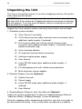
Unpacking the Unit
The sensor transmitter comes in a custom shipping container. Be careful
when removing the device.
CAUTION: Beware of damaging any of the wind transducers located at
the top of the three antennas. Dropping the device can break or damage
the transducers. If the antenna bends or twists, the re-aligning can be
difficult or impossible.
Unpack the Orion weather station and verify that all parts are included.
1. Standard system includes:
Orion Sensor Transmitter
50 ft sensor cable + additional cable length if ordered
Orion Interface Module
(2) 3-position terminal blocks
Interface module power supply
User Manual
6-foot RS-232 cable + additional cable length if ordered
2. Weather Display Console (Optional)
Display Console
Power supply
6-foot RS-232 cable + additional cable length if ordered
User manual
3. WeatherMaster software and user manual (Optional)
4. Weather MicroServer:
MicroServer
Power supply
Columbia Weather Systems, Inc.
32
Orion Weather Station
____________________________________________________________________
6-foot Ethernet cable
User manual
Inspect all system components for obvious shipping damage (Refer to
“Important Notice: Shipping Damage” in case of damage).
NOTE: Save the shipping carton and packing material in case the unit
needs to be returned to the factory. If the system does not operate or
calibrate properly, see Maintenance and Troubleshooting sections, for
further instructions.
Orion Weather Station
33
___________________________________________________________________
Installing the Orion Sensor Transmitter
Site Selection:
Finding a suitable site for the sensor transmitter is important in obtaining
representative ambient measurements. The site should represent the
general area of interest.
The sensor transmitter should be installed in a location that is free from
turbulence caused by nearby objects, such as trees or buildings.
WARNING: To protect personnel (and the device), a lightning rod should
be installed with the tip at least 40 inches (one meter) above the sensor
transmitter. The rod must be properly grounded, compliant with all local
applicable safety regulations.
Installing the Mounting Adapter
1. Insert the mounting adapter in the transmitter bottom side as
shown in the diagram above.
2. Turn the adapter firmly until you feel that it has snapped into the
locked position.
3. Align the transmitter in such a way that the arrow (at the bottom of
the transmitter) points to north (see North Alignment).
4. Tighten the fixing screw to fix the adapter firmly to the mast.
Columbia Weather Systems, Inc.
34
Orion Weather Station
____________________________________________________________________
North Alignment
To help the alignment, there is an arrow and text North on the bottom of
the transmitter. The transmitter should be aligned in such a way that this
arrow points to the north.
Wind direction can be referenced to true north, which uses the earth’s
geographic meridians, or magnetic north, which is read with a magnetic
compass. The magnetic declination is the difference in degrees between
the true north and magnetic north.
Compass Alignment
1. If the sensor transmitter is already mounted, loosen the fixing
screw on the mounting adapter.
2. Use a compass to determine that the transducer heads are
exactly in line with the compass and that the arrow on the bottom
of the transmitter points to north.
3. Tighten the fixing screw on the mounting adapter when done.
Once the sensor transmitter is aligned to north, the transmitter can be
removed from the mounting adapter without losing the north orientation.
Orion Weather Station
35
___________________________________________________________________
Installing the Mast
There are three acceptable methods for mounting the mast to a roof or
building structure: Sloped roof mounting, flat roof mounting or wall
mounting. See Optional Sensor Mounting Hardware for more
information.
Location
Do not attach the sensor transmitter to a radio transmitting mast or
tower.
Select a mounting location that will allow the sensor cable to be routed
away from other data cables to avoid interference. Never route sensor
cables in tall trees. Do not mount sensors close to power lines or
telephone lines. For normal roof mounting, the recommended minimum
distance from power or telephone lines is 25 ft. (8 m). Use extreme
caution when working close to power lines.
Mounting Method
Choose the appropriate mounting method for the installation and obtain
any necessary mounting hardware. Refer to Section 4 for information on
optional sensor mounting hardware and accessories which are available
from the factory.
If the mounting hardware is not obtained from the factory, be certain to
use metal parts which are plated or galvanized to assure maximum
longevity.
Secure the mast to the roof, using guy wires with sufficient tensile
strength or to building wall using a wall-mount hardware kit.
Routing Cable
Use plastic tie wraps to secure the cable to mast, particularly at the mast
base. Tighten the tie wraps securely and clip off any excess length with a
wire cutter tool.
Route the cable back to the Interface Module
CAUTION: There may be electric wires in the wall. When routing cable
through walls, we recommend that you shut off the electricity in the
room(s) where you are drilling.
Any mast or tower should always be properly earth grounded to minimize
electrical storm damage. The use of a properly grounded metal mast or
tower, however, does not insure protection from electrostatic discharge.
Columbia Weather Systems, Inc.
36
Orion Weather Station
____________________________________________________________________
These items could become electrically charged resulting in damage to
the sensors and/or console. This could damage the system in the event
of an electrical storm. Use insulated standoffs (user supplied, see
Section 4) when routing cable to help avoid this problem.
Note: If the standard 50 ft. cable provided with the sensor transmitter is
not long enough, it may be extended by splicing on an appropriate length
of 22-gauge, stranded, seven conductor shielded cable with the same
color code. When cutting and splicing, insure good contacts, proper color
coding of the terminal leads, and a good seal. (A good solder splice, and
water proof insulation are essential; merely twisting the respective wires
together is not adequate.) Additional cable (Catalog No. 81545) and a
water tight splice kit (Cat. No. 81580) are available from the factory.
Once the sensor transmitter has been placed, route the cable back to the
Interface Module.
Orion Weather Station
37
___________________________________________________________________
Connecting the Sensor Transmitter to the Interface
Module
Using a #1 Straight Slot screwdriver, attach the wires from the end of the
sensor cable to the terminal block screws on the Interface Module as
follows:
Terminal Number
1
2
3
4
5
6
Signal
+12 V
Ground
No Connection
Signal Ground
RX
TX
Color
RED
White and Bare
Green
Black
Orange
For heated sensor transmitters, connect the brown wire along with the
red wire to position 1 and connect the blue wire along with the white and
bare wires to terminal 2.
Columbia Weather Systems, Inc.
38
Orion Weather Station
____________________________________________________________________
Optional Sensor Mounting Hardware
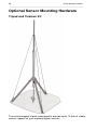
Tripod and Tiedown Kit
The meteorological tripod is designed to provide up to 10 feet of stable,
secure support for your meteorological sensors.
Orion Weather Station
39
___________________________________________________________________
Constructed from welded aluminum and powder coated for appearance
and longevity, the 15-pound tripod can easily support up to 60 pounds of
equipment. An optional tie-down kit allows for additional security in highwind areas.
To install, insert the legs into the main body and secure with stainless
steel retainer pins. Extend the mast to the desired height and insert
another retainer pin. Install the guy wires to complete the set-up.
Tripod Parts List:
Item # Description
Qty
1
Body/Mast Assembly
1
2
Legs
3
3
Retainer Pins
4
4
Guy Wire Ring with
1
3 Wires and Turnbuckles
Columbia Weather Systems, Inc.
40
Orion Weather Station
____________________________________________________________________
5
Anchor Screw with Chain
1
6
Clamp with Strap
1
7
Retainer Pin
1
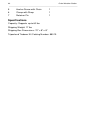
Specifications
Capacity: Supports up to 60 lbs.
Shipping Weight: 17 lbs
Shipping Box Dimensions: 70" x 8" x 8"
Tripod and Tiedown Kit Catalog Number: 88019
Orion Weather Station
41
___________________________________________________________________
Fiberglass and steel 10-foot masts are available for use with either Roof
Mounting Hardware Kit (Cat. No. 88002) or Wall Mounting Kit (Cat.
No.88003).
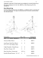
Roof Mounting
The Roof Mounting Kit (Cat. No. 88002) is suitable for both a slanted and
flat roof installation. The figure and table below illustrates and describes
the individual parts.
Description
Pkg. Ref
Catalog No.
Mast, 10 ft. (steel or fiberglass)
1
1
88005 / 88004
Universal Mast Mount
1
2
88010
Lag Screw, Roof Mast Mount
4
3
88030
Cable Standoffs, Wood Screw
4
5
88050
Guy Wire Clamps, 1/8"
3
4
88070
Steel Guy Wire, Galvanized
50 ft. 6
88080
Eye Bolt Wood Screws, 1/4" x 3"
4
88090
1/4" x 2 1/4" (for comp. roofs)
7
Columbia Weather Systems, Inc.
42
Orion Weather Station
____________________________________________________________________
Turnbuckles, 6" open x 4" closed
3
(not shown)
88100
Cable Nail Clips
20
8
88110
Cable Feed Through Bushings
4
10
88140
Orion Weather Station
43
___________________________________________________________________
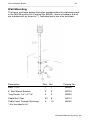
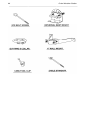
Wall Mounting
The figure and table below illustrates and describes the individual parts
in the Wall Mounting Kit (Catalog No. 88003). Items included in the kit
are marked with an asterisk (*). Individual parts are also available.
Description
Pkg. Ref
Catalog No.
Mast, 10 ft.
1
1
88005
4" Wall Mount Bracket
2
9
88120
*Lag Screw, 1/4" x 2 1/4"
4
3
88030
Cable Nail Clips
20
8
88110
Cable Feed Through Bushings
4
10
88140
* Not included in kit
Columbia Weather Systems, Inc.
44
Orion Weather Station
____________________________________________________________________
Orion Weather Station
45
___________________________________________________________________
SECTION 4: Vehicle Mount
Installation
Vehicle Mount System Configurations
Installation Overview
Unpacking the Unit
Installing the telescoping mast and truck-mount brackets
Installing the vehicle mount connector and routing cable
Installing the Interface Module
Installing and connecting the Weather Display Console and Computer
Software
Installing the Orion sensor transmitter and Quick-North Orientation
Columbia Weather Systems, Inc.
46
Orion Weather Station
____________________________________________________________________
Unpacking the Unit
The sensor transmitter comes in a custom shipping container. Be careful
when removing the device.
CAUTION: Beware of damaging any of the wind transducers located at
the top of the three antennas. Dropping the device can break or damage
the transducers. If any the antenna bends, twists re-aligning the sensor
can be difficult or impossible.
Unpack the Orion weather station and verify that all parts are included.
1. Standard system includes:
Orion Sensor Transmitter
15 ft external sensor cable and male sensor connector (plus
additional cable lengths, if ordered)
50 ft internal cable with vehicle mount female sensor
connector (plus additional cable lengths, if ordered) and allweather connector cap
Orion Interface Module
(2) 3-positon terminal block connectors
Interface module power supply
User Manual
6-foot RS-232 cable (plus additional cable lengths, if
ordered)
9 ft telescoping mast with vehicle-mount brackets
Mast extension sleeve adapter
2. Weather Display Console (Optional)
Display Console
Power supply
6-foot RS-232 cable (plus additional cable lengths, if
ordered)
User Manual
3. WeatherMaster Software, with User Manual (Optional)
Inspect all system components for obvious shipping damage (Refer to
“Important Notice: Shipping Damage” in case of damage).
Save the shipping carton and packing material in case the unit needs to
be returned to the factory. If the system does not operate or calibrate
Orion Weather Station
47
___________________________________________________________________
properly, see Maintenance and Troubleshooting sections, for further
instructions.
Installing the telescoping mast and
vehicle-mount brackets
1. Select a location on the vehicle where the Orion sensor mast will be
installed.
2. Three mounting brackets are included with the mast. The mounting
base plate and a spring-loaded securing mounting bracket will be
permanently mounted to the vehicle for quick and easy set up. The
third bracket is attached to the mast and mates with a slot on the
spring-loaded mounting bracket. This bracket may be loosened and
re-positioned on the mast to fit the installation scheme and mounting
bracket positioning. A spacer for the spring-loaded bracket is
provided to insure that the mast is 90° vertical.
3. Ensure the vehicle-mount sensor connector is in close proximity to
the mast’s mounting bracket location (refer to the vehicle-mount
sensor connector section below). Mark and drill the appropriate
mounting bracket holes. Be sure to allow for sufficient structural
backing, to adequately support the mast and sensor.
4. External sensor cabling is intended to hang freely along the side of
the mast. This assures the mast’s easy extension and retraction
without pinching, crimping, or cutting the sensor cable. Users may
tie-wrap the cable to the lower portion of the mast. The external
sensor cable has a male connector that couples to the vehicle-mount
female connector on the side of the vehicle.
5. To extend the mast, locate the large textured locking ring at the top
of the nested mast. This ring loosens and tightens the mast
extension. A counter-clockwise rotation loosens the ring and allows
the mast to be fully extended. Clockwise ring rotation tightens the
extension in place.
Columbia Weather Systems, Inc.
48
Orion Weather Station
____________________________________________________________________
Installing the vehicle mount sensor
connector and routing cable
1. To install the female vehicle-mount sensor connector, drill a ¾” hole
in close proximity to the sensor mast mounting bracket installation. A
recommended location is near the mast’s lower base bracket.
2. Drill four small pilot holes for the mounting screws.
3. Run 50-ft cable through the hole and route to the Orion Interface
Module location.
4. Connect the cable to the 3-position connectors, as listed in the chart
below.
5. Affix the connector with mounting screws on the external side of the
vehicle and ensure the associated all-weather connector cap is
securely attached.
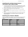
Installing the Interface Module
Using a #1 Straight Slot screwdriver, attach the wires from the end of the
sensor cable to the terminal block screws on the Interface Module as
follows:
Terminal Number
1
2
3
4
5
6
Signal
+12 V
Ground
No Connection
Signal Ground
RX
TX
Color
RED
White and Bare
Green
Black
Orange
Orion Weather Station
49
___________________________________________________________________
Connecting the Weather Display Console
and Computer
Connect the Weather Display Console to the Orion Interface Module
using the RJ-11 cable. The Display Console can be connected to either
serial port 1 or 2
Connect the Orion Interface Module to the computer using the RJ-11 and
DB-9 connector (RS-232 Interface). The computer can be connected to
either serial port 1 or 2. On the computer end, the DB-9 connector is
plugged into the computer serial port (normally COM port 1). If the
computer does not have a serial port, then a USB to Serial Port
converter will be needed.
Columbia Weather Systems, Inc.
50
Orion Weather Station
____________________________________________________________________
Installing the sensor transmitter and North
Orientation
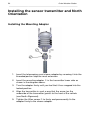
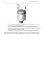
Installing the Mounting Adapter
1. Insert the telescoping mast sleeve adapter by screwing it into the
threaded portion atop the mast extension.
2. Insert the mounting adapter in the transmitter lower side as
shown in the diagram above.
3. Turn the adapter firmly until you feel that it has snapped into the
locked position.
4. Align the transmitter in such a way that the arrow (on the
underside of the transmitter) points to the front of the vehicle
(see North Alignment).
5. Tighten the Allen screw to firmly and permanently fix the
adapter firmly to the sleeve adapter.
Orion Weather Station
51
___________________________________________________________________
North Alignment
North Orientation: Locate the alignment arrow and text North on the
underside of the transmitter. With the mast mounted on the vehicle,
extend the mast to its fullest extension. Before tightening the mast into
place, use the field compass provided to orient the transmitter in such a
manner that the alignment arrow points to Magnetic North. Rotate the
mast extension until the sensor is properly oriented. Tighten the locking
nut.
Wind direction can refer to either Magnetic North, which is read with a
magnetic compass, or True North, which uses the earth’s geographic
meridians. The magnetic declination is the difference in degrees between
the true north and magnetic north.
Columbia Weather Systems, Inc.
52
Orion Weather Station
____________________________________________________________________
1. If the sensor transmitter is already mounted, loosen the fixing
screw on the mounting adapter.
2. Use a compass to determine that the transducer heads are
exactly in line with the compass and that the arrow on the bottom
of the transmitter points to north.
3. Tighten the fixing screw on the mounting adapter when done.
Once the sensor transmitter is aligned to north, the transmitter can be
removed from the mounting adapter without losing the north orientation.
Orion Weather Station
53
___________________________________________________________________
SECTION 5: Nomad Portable
Installation
Installation Overview
Orion Nomad System Configurations
Orion Nomad with WeatherMaster Software:
Columbia Weather Systems, Inc.
54
Orion Weather Station
____________________________________________________________________
Orion Nomad with Weather Display Console:
Orion Nomad with WeatherMaster Software and Weather Display
Console:
Orion Weather Station
55
___________________________________________________________________
Orion Nomad with Weather MicroServer:
Unpacking the Unit
CAUTION: Beware of damaging any of the wind transducers located at
the top of the three antennas. Dropping the device can break or damage
the transducers. If the antenna bends or twists, the re-aligning can be
difficult or impossible.
Standard system includes:
1. System Carrying Case
Orion Nomad Sensor Transmitter
15 ft sensor cable
2.4 GHz Transceiver and antenna
(2) 12 volts Batteries
Battery Charger
User Manual
2. Tripod
Guy wire and collar
Tie-down kit
Canvas tripod bag
Columbia Weather Systems, Inc.
56
Orion Weather Station
____________________________________________________________________
3. Receiving Transceiver
2.4 GHz Transceiver and antenna
6-foot RS-232 Transceiver cable
Orion Interface Module (optional)
4. Weather Display Console (Optional)
Display console
Power supply
6-foot RS-232 cable
User manual
5. WeatherMaster software (Optional)
Software CD
User manual
6-foot computer cable
6. Weather MicroServer (Optional)
MicroServer
User manual
7-foot Ethernet cable
Power supply
Inspect all system components for obvious shipping damage (Refer to
“Important Notice: Shipping Damage” in case of damage).
Save the shipping carton and packing material in case the unit needs to
be returned to the factory.
Orion Weather Station
57
___________________________________________________________________
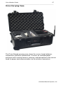
Orion Carrying Case
The Orion Nomad carrying case stores the sensor head, batteries,
transceivers and other accessories. It serves as a weatherproof
enclosure with a wiring harness, antenna, and connection to the sensor
head for power and communication via the wireless transceiver.
Columbia Weather Systems, Inc.
58
Orion Weather Station
____________________________________________________________________
Tripod and Tiedown Kit
The meteorological tripod is designed to provide up to 10 feet of stable,
secure support for your meteorological sensors.
Constructed from welded aluminum and powder coated for appearance
and longevity, the 15-pound tripod can easily support up to 60 pounds of
Orion Weather Station
59
___________________________________________________________________
equipment. An optional tie-down kit allows for additional security in highwind areas.
To install, insert the legs into the main body secure with stainless steel
retainer pins. Extend the mast to the desired height and insert another
retainer pin. Install the guy wires to complete the set-up.
Tripod Parts List:
Item # Description
Qty
1
Body/Mast Assembly
1
2
Legs
3
3
Retainer Pins
4
4
Guy Wire Ring with
1
3 Wires and Turnbuckles
5
Anchor Screw with Chain
1
Columbia Weather Systems, Inc.
60
Orion Weather Station
____________________________________________________________________
6
Clamp with Strap
1
7
Retainer Pin
1
Specifications
Capacity: Supports up to 60 lbs.
Shipping Weight: 17 lbs
Shipping Box Dimensions: 70" x 8" x 8"
Tripod and Tiedown Kit Catalog Number: 88019
Orion Weather Station
61
___________________________________________________________________
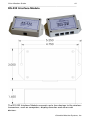
RS-232 Interface Module
The RS-232 Interface Module connects up to four devices to the wireless
transceiver, such as computers, display consoles and other such
devices.
Columbia Weather Systems, Inc.
62
Orion Weather Station
____________________________________________________________________
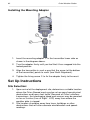
Installing the Mounting Adapter
1. Insert the mounting adapter in the transmitter lower side as
shown in the diagram above.
2. Turn the adapter firmly until you feel that it has snapped into the
locked position.
3. Align the transmitter in such a way that the arrow (at the bottom
of the transmitter) points to north (see North Alignment).
4. Tighten the fixing screw to fix the adapter firmly to the mast.
Set Up Instructions
Site Selection:
1. Upon arrival at the deployment site, determine a suitable location
where the Orion Nomad mast may be set up away from physical
obstructions and heavy foot traffic. Because of Orion’s wireless
transceivers, the telescoping tripod and sensors may be remoted
as far as 3-miles (Line of Sight - LOS) away from where the
weather data is viewed.
2. Site location should be away from trees, buildings or other
obstructions that will alter accurate wind direction and speedreadings.
Orion Weather Station
63
___________________________________________________________________
3. Screw the grounding/tie-down auger into the ground at the
center of the placement until the auger portion is adequately
secured.
4. If the site selection is on blacktop/pavement, use a 6” nail spike
or Rebar driven into the surface at a 45° angle. This sufficiently
secures the mast during operations.
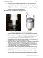
Mast Set Up and Sensor Alignment:
Figure 1. Tripod North Orientation Alignment
1. Remove tripod components from the bag. Stand the tripod up
(without legs) so the sensor head may be attached to the mast.
2. The mounting bracket/alignment adapter should be permanently
secured to the mast. NOTE: THE ALIGNMENT ARROW ON
THE MAST AND THE BLACK TICK-MARK ON THE
ALIGNMENT ADAPTER SHOULD ALWAYS BE ALIGNED TO
ENSURE PROPER NORTH ORIENTATION.
3. Attach the Sensor Head to the alignment adapter by aligning the
female slots on the Sensor Head to the male teeth on the
alignment adapter. NOTE: THE RUBBER SLOT COVER ON
THE SENSOR HEAD SHOULD ALIGN WITH THE ADAPTER
TICK-MARK AND MAST MARKING ARROW.
4. Attach sensor cable by connecting the 8-pin waterproof male
connector/sensor cable to the one-foot female sensor pig-tail
waterproof connector.
5. Holding the tripod vertical, place tripod legs in their respective
slots, one leg at a time. Once the first leg is in, balance the tripod
until the other legs are inserted and the tripod is free standing.
Columbia Weather Systems, Inc.
64
Orion Weather Station
____________________________________________________________________
6. With all legs in place, insert the leg locking pins. The tripod may
now be picked up and moved around for final placement and
North Orientation over the grounding stake.
7. Secure the tripod to the grounding stake using the spring-loaded
chain. Ensure the chain is tight enough to keep the tripod inplace during high winds, but not so tight to fully extend the
spring.
8. Using the attached compass, locate magnetic North. Point the
opposite (front) tripod leg and align it North (magnetic North).
Because the wind sensor and alignment arrows have already
been aligned, the entire mast and wind sensor is now configured
to magnetic North. See Figure 2.
Figure 2. Tripod North Orientation Diagram
9. Extend the mast to its fullest height and insert the locking pin.
NOTE: MAST POSITION ARROWS MUST BE PROPERLY
ALIGNED TO ENSURE NORTH ORIENTATION.
10. If the guy wire kit is used, remove the alignment adapter prior to
mast set up and slide the guy wire ring collar onto the mast
extension, then reinstall the alignment adapter. Anchor the end
of each guy wire to the corresponding tripod foot using the wing
nuts. Extend the mast fully and adjust the guy wires using the
turnbuckles to tighten the guy wires evenly.
Orion Weather Station
65
___________________________________________________________________
Transportation Case and Sensor Plug-In
1. Place the Orion Nomad transportation case at the foot of the
tripod.
2. Attach the 8-inch wireless antenna to the antenna cable on the
outside of the case.
3. Plug the 8-pin Female Sensor Cable to the 8-pin male connector
on the outside of the case.
4. Ensure the red/black power cord connectors are connected to
their respective battery terminals inside the case.
5. Latch and Seal the case to the internal components from the
weather elements.
Battery Power System
1. The Orion Nomad comes with a Battery Power System that
consists of two 12VDC, 7.5AH batteries and a 12-Volt battery
charger. One battery will continuously operate the Orion Nomad
for approximately 60 hours. One battery is intended to be
charging while the other is in operation.
2. Swap batteries, as necessary to continue weather station
operations.
Operation
Once Mast is set up, with the Sensor Head attached & aligned, plug the
red/black power terminals to the corresponding battery terminals. The
Orion will automatically sense and transmit weather data via wireless
transceiver.
1. Transceiver Power/Connectivity/Transmission:
a) Check for the red power light
b) Check for the steady green connectivity light
c) Check for the one-second green pulsing/blinking
transmission light
2. Once the transceiver lights are all operational, data is being
transmitted. If the green transmission light is not blinking once
per second, data is not being transmitted. Re-check the RS-232,
power, and antenna connections.
Columbia Weather Systems, Inc.
66
Orion Weather Station
____________________________________________________________________
Monitoring
The data transmitted from the remote sensor can be monitored using the
Weather Display console, computer weather software, and/or Weather
MicroServer.
Connect the wireless transceiver to the appropriate device. Please refer
to the system diagrams in the beginning of this chapter.
Orion Weather Station
67
___________________________________________________________________
SECTION 6: Orion Sensor Data
Output Definition
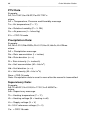
Wind data is transmitted every second, PTU data is transmitted every 15
seconds, and Precipitation data is transmitted every 0.01 inch
accumulation. A Supervisory message is transmitted every 60 seconds
when heating is turned off and every 15 seconds when heating is turned
on.
The RS-232 interface is as follows:
Bits per Second (baud rate): 9600
Data bits: 8
Parity: None
Stop bits: 1
Flow control: None
Note: The # sign after a parameter value indicates an invalid value.
Wind data
Example:
0r1,Dn=240D,Dm=249D,Dx=260D,Sn=4.3S,Sm=4.9S,Sx=5.4SMCO
where
0r1 = Wind message
Dn = Wind direction minimum (D = degrees)
Dm = Wind direction average (D = degrees)
Dx = Wind direction maximum (D = degrees)
Sn = Wind speed minimum (S = mph)
Sm = Wind speed average (S = mph)
Sx = Wind speed maximum (S = mph)
MCO = CRC-16 code
Columbia Weather Systems, Inc.
68
Orion Weather Station
____________________________________________________________________
PTU Data
Example :
0r2,Ta=73.4F,Ua=26.3P,Pa=29.71IE^x
where
0r2 = Temperature, Pressure and Humidity message
Ta = Air temperature (F = °F)
Ua = Relative humidity (P = % RH)
Pa = Air pressure (I = Inhes Hg)
E^x = CRC-16 code
Precipitation Data:
Example:
0r3,Rc=0.010I,Rd=2530s,Ri=0.01I,Hc=0I,Hd=0s,Hi=0INmo
where
0r3 = Precipitation message
Rc = Rain accumulation (I = inches)
Rd = Rain duration (s = s)
Ri = Rain intensity (I = inches/h)
2
Hc = Hail accumulation (M = hits/in )
Hd = Hail duration (s = s)
2
Hi = Hail intensity (M = hits/ in h)
Nmo = CRS-16 code
Note: Precipitation data is reset to zero after the record is transmitted.
Supervisory Data:
Example:
0r5,Th=69.0F,Vh=0.0N,Vs=17.0V,Vr=3.483VCa~
where
0r5= Supervisory message
Th = Heating temperature (F = °F)
Vh = Heating voltage (N = heating is off)
Vs = Supply voltage (V = V)
Vr= 3.5 V reference voltage (V = V)
Ca~ = CRS-16 code
Orion Weather Station
69
___________________________________________________________________
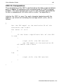
CRC-16 Computation
The computation of the CRC is performed on the data response before
parity is added. All operations are assumed to be on 16 bit unsigned
integers. The least significant bit is on the right. Numbers preceded by
0x are in hexadecimal. All shifts shift in a zero. The algorithm is:
Initialize the CRC to zero. For each character beginning with the
address, up to but not including the carriage return (<cr>), do as
follows:
{
Set the CRC equal to the exclusive OR of the
character and itself
for count =1 to 8
{
if the least significant bit of the CRC
is one
{
right shift the CRC one bit
set CRC equal to the exclusive OR
of 0xA001 and itself
}
e
lse
{
right shift the CRC one bit
}
}
}
Columbia Weather Systems, Inc.
70
Orion Weather Station
____________________________________________________________________
Encoding the CRC as ASCII Characters
The 16 bit CRC is encoded to three ASCII characters by using the
following algorithm:
1st character = 0x40 OR (CRC shifted right 12 bits)
2nd character = 0x40 OR ((CRC shifted right 6 bits) AND 0x3F)
3rd character = 0x40 OR (CRC AND 0x3F)
The three ASCII characters are placed between the data and <cr><lf>.
Parity is applied to all three characters, if selected for the character
frame.
The CRC computation code is added to the end of the response, if the first
letter of the command is sent by using lower case.
Orion Weather Station
71
___________________________________________________________________
SECTION 7: CALIBRATION
Factory Calibration
The wind sensor is checked in a zero wind verifier that meets Vaisala’s
manufactured specifications. The pressure, temperature and relative
humidity module is tested against a Vaisala PTU200 working standard.
The measurement of humidity, temperature and pressure are each
verified against the PTU200 working standard prior to shipment. The
PTU200 pressure measurement is calibrated against a Vaisala PTB220
barometer and is traceable to the National Institute of Standards and
Technology (NIST) via Vaisala’s Measurement Standards Laboratory
(MSL). The PTU200 temperature measurement is calibrated against a
Hart 1560 working standard in a liquid bath at Vaisala’s MSL and is
traceable to NIST. The PTU200 humidity measurement is calibrated
against two Vaisala HMP233 working standards which are calibrated
against a HYGRO M3 dewpoint meter. The HYGRO M3 dewpoint meter
is calibrated in Vaisala’s MSL and is traceable to NIST. Vaisala’s MSL
has been accredited by FINAS according to ISO.IEC 17025.
The Zero wind verifier measures the ultrasonic speed transmitter and
received in zero-wind environment. Once this is calibrated, the wind
readings will be accurate over the full range of the sensor.
Columbia Weather Systems, Inc.
72
Orion Weather Station
____________________________________________________________________
Temperature and Pressure Reading
Adjustments
Even though the temperature sensor is calibrated at the factory to ±0.5°
F and requires no further calibration, and similarly the pressure sensor is
calibrated to ±0.015 inches Hg, the sensors reading can be adjusted
using WeatherMaster software or the Weather Display console. Please
refer to their user manual for more information.
Orion Weather Station
73
___________________________________________________________________
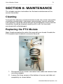
SECTION 8: MAINTENANCE
This chapter contains instructions for the basic maintenance of the
sensor transmitter.
Cleaning
To ensure the accuracy of measurement results, the sensor transmitter
should be cleaned when it becomes contaminated. Leaves and other
such particles should be removed from the precipitation sensor and the
transmitter should be cleaned carefully with a soft, lint-free cloth
moistened with mild detergent.
Replacing the PTU Module
Note: Avoid contacting the white filter cap with your hands. Handle the
PTU module from the plastic connector base (5).
1. Disconnect Orion sensor connector from cable and remove from
mounting adapter.
2. Loosen the three screws at the bottom of sensor and slide out
completely as shown below.
Columbia Weather Systems, Inc.
74
Orion Weather Station
____________________________________________________________________
3. Remove the base section and disconnect the flat ribbon cable.
4. Pull out the top of the sensor.
5. Release the small white flap and remove the PTU module.
6. Connect a new PTU module, replace the top, re-connect the flat
ribbon cable, replace the base and tighten the three bottom
screws.
7. Re-install on mounting adapter and reconnect cable connector.
Factory Calibration and Repair Service
Send the device to Columbia Weather Systems, Inc. for calibration and
adjustment, see Section 9: USER SUPPORT INFORMATION for more
information.
Orion Weather Station
75
___________________________________________________________________
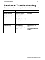
Section 9: Troubleshooting
This chapter describes common problems, their probable causes and
remedies.
Problem
Possible Cause
Action
Wind measurement
failure. Both the
speed and direction
sensors are not
reporting correct
data
Blockage (trash,
leaves, branches,
bird nests) between
the wind
transducers.
Remove the
blockage.
Pressure, humidity
or temperature
measurement
failure.
PTU module may
not be properly
connected. There
may be water in the
PTU module.
Check that the wind
transducers are not
damaged.
Ensure the proper
connection of the
PTU module.
Remove and dry the
module.
Columbia Weather Systems, Inc.
76
Orion Weather Station
____________________________________________________________________
Orion Weather Station
77
___________________________________________________________________
SECTION 10: USER SUPPORT
INFORMATION
This section consists of the following items:
1. One-Year Limited Warranty: Please read this document carefully.
2. Return for Repair Procedure: This procedure is for your convenience
in the event you must return your Orion for repair or replacement.
Follow the packing instructions carefully to protect your instrument in
transit.
Limited Warranty
Columbia Weather Systems, Inc. (CWS), warrants the Orion Weather
Station to be free from defects in materials and/or workmanship when
operated in accordance with the manufacturer’s operating instructions,
for one (1) years from date of purchase, subject to the provisions
contained herein. CWS warranty shall extend to the original purchaser
only and shall be limited to factory repair or replacement of defective
parts.
EXCLUSIONS
Certain parts are not manufactured by CWS (i.e., certain purchased
options, etc.) and are therefore not covered by this warranty. These parts
may be covered by warranties issued by their respective manufacturers
and although CWS will not warrant these parts, CWS will act as agent for
the administration of any such independent warranties during the term of
this warranty. This warranty does not cover normal maintenance,
damage resulting from improper use or repair, or abuse by the operator.
Damage caused by lightning or other electrical discharge is specifically
excluded. This warranty extends only to repair or replacement, and shall
in no event extend to consequential damages. In the event of operator
repair or replacement, this warranty shall cover neither the advisability of
the repair undertaken, nor the sufficiency of the repair itself.
THIS DOCUMENT REFLECTS THE ENTIRE AND EXCLUSIVE
UNDERSTANDING OF THE PARTIES, AND EXCEPT AS OTHERWISE
PROVIDED HEREIN, ALL OTHER WARRANTIES, EXPRESS OR
IMPLIED, PARTICULARLY THE WARRANTIES OF MERCHANT
Columbia Weather Systems, Inc.
78
Orion Weather Station
____________________________________________________________________
ABILITY AND/OR FITNESS FOR A PARTICULAR PURPOSE ARE
EXCLUDED.
This warranty gives you specific legal rights, and you may also have
other rights which vary from state to state.
Return for Repair Procedure
1.
In the event of defects or damage to your unit, first call the
Service Department Monday through Friday, 8:30 am to 4:00 pm
PST, (503) 629-0887 to determine the advisability of factory
repair. The Service Department will issue an RMA number
(Return Merchandise Authorization) to help us identify the
package when received. Please write that number on the outside
of the box.
2.
In the event factory service is required, return your Orion
Weather Station as follows:
A.
Packing
Wrap the Sensor Transmitter in a plastic bag first.
Pack in original shipping carton or a sturdy oversized
carton.
Use plenty of packing material.
B.
Include:
A brief description of the problem with all known
symptoms.
Your telephone number.
Your return street shipping address (UPS will not deliver
to a P.O. box).
Write the RMA number on the outside of the box.
C.
Shipping
Send freight prepaid (UPS recommended).
Insurance is recommended. (The factory can provide the
current replacement value of the item being shipped for
insurance purposes.)
Orion Weather Station
79
___________________________________________________________________
D.
Send to:
Columbia Weather Systems, Inc.
2240 NE Griffin Oaks Street, Suite 100
Hillsboro, Oregon 97124
E.
C.O.D. shipments will not be accepted.
3.
If your unit is under warranty, after repair or replacement has
been completed, it will be returned by a carrier and method
chosen by Columbia Weather, Inc. to any destination within the
continental U.S.A. If you desire some other specific form of
conveyance or if you are located beyond these borders, then you
must bear the additional cost of return shipment.
4.
If your unit is not under warranty, we will call you with an
estimate of the charges. If approved, your repaired unit will be
returned after all charges, including parts, labor and return
shipping and handling, have been paid. If not approved, your unit
will be returned as is via UPS COD for the amount of the UPS
COD freight charges.
Columbia Weather Systems, Inc.
80
Orion Weather Station
____________________________________________________________________
Orion Weather Station
81
___________________________________________________________________
Reference
Glossary
Aspirating Radiation Shield
A device used to shield a sensor such as a temperature probe from
direct and indirect radiation and rain while providing access for
ventilation.
Barometric Pressure
The pressure exerted by the atmosphere as a consequence of
gravitational attraction exerted upon the “column” of air lying directly
above the point in question.
Celsius Temperature Scale
A temperature scale with the ice point at 0 degrees and the boiling point
of water at 100 degrees.
Dew Point
The temperature to which a given parcel of air must be cooled at
constant pressure and constant water-vapor content in order for
saturation to occur. When this temperature is below 0°C, it is sometimes
called the frost point.
Fahrenheit Temperature Scale
A temperature scale with the ice point at 32 degrees and the boiling point
of water at 212 degrees.
Heat Index
The heat index or apparent temperature is a measure of discomfort due
to the combination of heat and high humidity. It was developed in 1979
and is based on studies of evaporative skin cooling for combinations of
temperature and humidity.
Columbia Weather Systems, Inc.
82
Orion Weather Station
____________________________________________________________________
Relative Humidity
Popularly called humidity. The ratio of the actual vapor pressure of the
air to the saturation vapor pressure.
Sea Level Pressure
The atmospheric pressure at mean sea level, either directly measured
or, most commonly, empirically determined from the observed station
pressure.
In regions where the earth’s surface pressure is above sea level, it is
standard observational practice to reduce the observed surface pressure
to the value that would exist at a point at sea level directly below.
Wind Chill
That part of the total cooling of a body caused by air motion.
Orion Weather Station
83
___________________________________________________________________
Unit Conversion
Speed
Kilometers per hour = 1.610 x miles per hour
Knots = 0.869 x miles per hour
Meters per second = 0.448 x miles per hour
Feet per second = 1.467 x miles per hour
Temperature
Temperature in °C = 5/9 (temperature in °F - 32)
Temperature in °F = (1.8 x temperature in °C) + 32
Distance
Millimeters = 25.4 x inches
Pressure
Millibars = 33.86 x inches of mercury
Kilopascals = 3.386 x inches of mercury
Pounds per square inch = 0.49 x inches of mercury
Standard atmospheres = 0.0334 x inches of mercury
Columbia Weather Systems, Inc.
84
Orion Weather Station
____________________________________________________________________
Tables and Formulas
Wind Chill Chart
In 2001, NWS implemented an updated Wind chill Temperature (WCT)
index. The change improves upon the former WCT Index used by the
NWS and the Meteorological Services of Canada, which was based on
the 1945 Siple and Passel Index.
In the fall of 2000, the Office of the Federal Coordinator for
Meteorological Services and Supporting Research (OFCM) formed a
group consisting of several Federal agencies, MSC, the academic
community (Indiana University-Purdue University in Indianapolis (IUPUI),
University of Delaware and University of Missouri), and the International
Society of Biometeorology to evaluate and improve the windchill formula.
The group, chaired by the NWS, is called the Joint Action Group for
temperature Indices (JAG/TI). JAG/TI's goal is to upgrade and
standardize the index for temperature extremes internationally (e.g. Wind
chill Index).
The current formula uses advances in science, technology, and
computer modeling to provide a more accurate, understandable, and
useful formula for calculating the dangers from winter winds and freezing
temperatures.
Orion Weather Station
85
___________________________________________________________________
Wind Chill Equation
WC = 35.74 + 0.6215 T -35.75(V
0.16
) + 0.4275 T(V
0.16
)
Where:
WC = wind chill temperature in °F
V = wind velocity in mph
T = air temperature in °F
Note: Wind chill Temperature is only defined for temperatures at or
below 50 degrees F and wind speeds above 3 mph.
Columbia Weather Systems, Inc.
86
Orion Weather Station
____________________________________________________________________
Heat Index
Temperature in °F
70
75
80
85
90
95
100 105 110 115 120 125 130 135
0
64
66
73
78
83
87
91
95
99
5
64
69
74
79
84
88
93
97
102 107 111 116 122 126
10
65
70
75
80
85
90
95
100 105 111 116 123 131
15
65
71
76
81
86
91
97
102 108 115 123 131
20
66
72
77
82
87
93
99
105 112 120 130 141
25
66
72
77
83
88
94
101 109 117 127 139
30
67
73
78
84
90
96
104 113 123 135 148
35
67
73
79
85
91
98
107 118 130 143
40
68
74
79
86
93
101 110 123 137 151
45
68
74
80
87
95
104 115 129 143
50
69
75
81
88
96
107 120 135 150
55
69
75
81
89
98
110 126 142
60
70
76
82
90
100 114 132 149
65
70
76
83
91
102 119 138
70
70
77
84
93
106 124 144
75
70
77
85
95
109 130 150
80
71
78
86
97
113 136
85
71
78
87
99
117 140
90
71
79
88
102 122 150
95
71
79
89
105 126
100
72
80
90
108 131
RH
103 107 111 117 120
Orion Weather Station
87
___________________________________________________________________
Dew Point
B = (ln (RH/100) + ((17.2694*T) / (238.3+T))) / 17.2694
Dew Point in °C = (238.3 * B) / (1-B)
Where:
RH = Relative Humidity
T = Temperature in °C
Ln = Natural logarithm
Columbia Weather Systems, Inc.
88
Orion Weather Station
____________________________________________________________________
Columbia Weather Systems, Inc.
2240 NE Griffin Oaks Street, Suite 100
Hillsboro, OR 97124-6463
Telephone
(503) 629-0887
Fax
(503) 629-0898
Web Site
http://www.columbiaweather.com
Email
[email protected]
Catalog Number: 81650
Version 2.00
Printed in U.S.A.