1
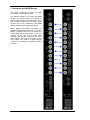
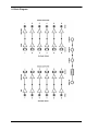
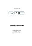
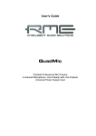
User's Guide
MADI Converter
6 x Bidirectional
MADI Optical to BNC Converter
6 coaxial Inputs and Outputs
6 optical Inputs and Outputs
1 to 3 MIDI Distributor
Contents
Important Safety Instructions ..................................3
1
2
3
4
5
6
7
8
9
10
11
2
Introduction ...............................................................4
Package Contents .....................................................4
Technical Specifications ..........................................4
3.1 Inputs......................................................................4
3.2 Outputs...................................................................5
Operation ...................................................................5
Operation with MADI Bridge ....................................6
Inputs and Outputs
6.1 MADI Inputs ...........................................................7
6.2 MADI Outputs.........................................................7
6.3 MIDI Input and Outputs ..........................................7
Technical Background
7.1 MADI Basics...........................................................8
7.2 MADI Converter Technology..................................9
Block Diagram .........................................................10
Warranty...................................................................11
Appendix ..................................................................11
Declaration of Conformity ......................................12
User's Guide MADI Converter © RME
Important Safety Instructions
ATTENTION! Do not open chassis – risk of electric shock
The unit has non-isolated live parts inside. No user serviceable parts inside.
Refer service to qualified service personnel.
Mains
• The device must be earthed – never use it without proper grounding
• Do not use defective power cords
• Operation of the device is limited to the manual
• Use same type of fuse only
To reduce the risk of fire or electric shock do not expose this device to rain or
moisture. Prevent moisture and water from entering the device. Never leave
a pot with liquid on top of the device. Do not use this product near water, i. e.
swimming pool, bathtub or wet basement. Danger of condensation inside –
don't turn on before the device has reached room temperature.
Installation
Surface may become hot during operation – ensure sufficient ventilation.
Avoid direct sun light and do not place it near other sources of heat, like radiators or stoves. When mounting in a rack, leave some space between this
device and others for ventilation.
Unauthorized servicing/repair voids warranty. Only use accessories
specified by the manufacturer.
Read the manual completely. It includes all information necessary
to use and operate this device.
User's Guide MADI Converter © RME
3
1. Introduction
The MADI Converter is a useful tool for any kind of MADI signal. The device converts MADI
digital audio streams from optical format to coaxial and from coaxial to optical. The compact 19"
device with 1 unit height contains six bi-directional converters, operating fully independently. All
12 inputs are equipped with status LEDs on the front panel.
All input signals will pass through absolutely unaltered. The MADI converter will operate with
any MADI format, be it 56-channel, 64-channel, any sample rate, even out-of-spec data rates
and violations of the MADI standard. Special equalisation and highly sensitive input stages allow distances of up to 100 meters using coaxial cables – even between multiple units.
Additionally, a MIDI distributor copies one MIDI input signal to three MIDI outputs, removing the
need for an external MIDI distributor.
The MADI converter is an ideal companion to RME's MADI Bridge. The Bridge's six coaxial
inputs and outputs can be converted to optical, a format which is advantageous in live and installed setups, and for longer cable lengths. The device can be placed underneath the MADI
Bridge ideally. The coaxial BNC inputs and outputs of the two devices will be right next to each
other vertically, and can be connected with short patch cables without cable crossing and cluttering.
2. Package Contents
Please check that your MADI Converter package contains each of the following:
• MADI Converter
• Manual
• Power chord
3. Technical Specifications
3.1 General
•
•
•
•
•
•
•
Power supply: Internal switching PSU, 100 - 240 V AC, 20 Watts
Typical power consumption: 15 Watts
Dimensions including rack ears (WxHxD): 483 x 44 x 242 mm (19" x 1.73" x 9.5")
Dimensions without rack ears/handles (WxHxD): 436 x 44 x 235 mm (17.2" x 1.73" x 9.3")
Weight: 2 kg ( 4.4 lbs)
Temperature range: +5° up to +50° Celsius (41° F up to 122°F)
Relative humidity: < 75%, non condensing
3.2 Inputs
MADI
• Coaxial via BNC, 75 Ohm, according to AES10-1991
• High-sensitivity input stage (< 0.2 Vpp)
• Optical via FDDI duplex SC connector
• 62.5/125 and 50/125 compatible
• Accepts any MADI signal
4
User's Guide MADI Converter © RME
MIDI
• 1 x 16 channels MIDI
• 5-pin DIN jack
• Opto-coupled, ground free input
• Fixed MIDI Thru functionality
3.3 Outputs
MADI
• Coaxial via BNC, 75 Ohm, according to AES10-1991
• Output voltage > 400 mVpp
• Cable length: more than 100 m
• Optical via FDDI duplex SC connector
• 62.5/125 and 50/125 compatible
• Fiber length: up to 2,000 m
MIDI
• 3 x 16 channels MIDI
• 5-pin DIN jacks
4. Operation
The user interface of the MADI Converter is characterized by a clearly structured architecture
and an unambiguous labelling of the front and rear sides.
The status of the 12 inputs is displayed by dedicated LEDs on the front panel.
The rear of the MADI Converter hosts six coaxial BNC inputs and outputs, six optical inputs and
outputs, one MIDI input and 3 MIDI Thru outputs, all of them presented and labelled in a clear
and tidy way.
The specially developed internal high performance switching power supply allows operation of
the MADI converter with voltages ranging from 100 to 240 V AC. It is short-circuit-proof, has an
integrated line-filter, is fully regulated against voltage fluctuations, and suppresses mains interference.
Notes
•
The INPUT LEDs of the MADI inputs are designed to light up with typical MADI signals. But
there is no real MADI detection and verification. Therefore, corrupt or non-standardized signals as well as high-frequency signals can cause the LEDs to turn on as well.
•
The MIDI INPUT LED shows any MIDI activity, including MIDI Clock, MTC and Active Sensing. The latter is sent by most keyboards every 0.3 seconds.
User's Guide MADI Converter © RME
5
5. Operation with MADI Bridge
The MADI converter is also an
companion to RME's MADI Bridge.
ideal
The MADI Converter can convert the MADI
Bridge's six coaxial inputs and outputs to
optical, a format which is advantageous in live
and installed setups, and for longer cable
lengths. So in this combination, the MADI
Bridge effectively offers eight optical I/Os.
MADI Bridge and MADI Converter are
perfectly designed for each other. In case the
Bridge is placed above the Converter, the
coaxial BNC inputs and outputs of the two
devices will be right next to each other
vertically, and can be connected with short
patch cables. Thanks to interchanged inputs
and outputs, the cabling is done without
crossing and cluttering, maintaining perfect
overview.
6
User's Guide MADI Converter © RME
6. Inputs and Outputs
6.1 MADI Inputs
The rear of the MADI Converter has six coaxial MADI inputs, available as BNC sockets. The
sockets are ground-free and separated from ground by capacitive coupling. This method prevents ground loops and other distortions by potential differences between the connected units.
Note that the transmission at the receiver still operates unbalanced.
The BNC input's ground-free design is built according to AES10-1991. The input's impedance is
75 Ohm. It will operate error-free from about 180 mVpp.
The two optical inputs use a FDDI (ISO/IEC 9413-3) compatible optical module each, according
to AES10-1991. More information can be found in chapter 7.1, MADI Basics.
6.2 MADI Outputs
The rear of the MADI Converter has six coaxial MADI outputs, available as BNC sockets. The
BNC outputs are built according to AES10-1991. The output impedance is 75 Ohm. The output
voltage will around 400 mVpp when terminated with 75 Ohm.
The six optical outputs use a FDDI (ISO/IEC 9413-3) compatible optical module each, according to AES10-1991. More information can be found in chapter 10.1, MADI Basics.
6.3 MIDI Input and Output
The rear of the MADI Converter offers one MIDI input and three MIDI outputs via 5-pin DIN
jacks. All MIDI data at the MIDI input are passed on and copied to the outputs, a method known
as MIDI Thru function.
User's Guide MADI Converter © RME
7
7. Technical Background
7.1 MADI Basics
MADI, the serial Multichannel Audio Digital Interface, has been defined already in 1989 as an
extension of the existing AES3 standard following several manufacturers' wish. The format also
known as AES/EBU, a balanced bi-phase signal, is limited to two channels. Simply put, MADI
contains 28 of those AES/EBU signals in serial, i. e. after one another, and the sample rate can
still even vary by +/-12.5%. The limit which cannot be exceeded is a data rate of 100 Mbit/s.
Because an exact sampling frequency is used in most cases, the 64 channel mode was introduced officially in 2001. It allows for a maximum sample rate of 48 kHz + ca. 1%, corresponding
to 32 channels at 96 kHz, without exceeding the maximum data rate of 100 Mbit/s. The effective
data rate of the port is 125 Mbit/s due to additional coding.
Older devices understand and generate only the 56 channel format. Newer devices often work
in the 64 channel format, but offer still no more than 56 audio channels. The rest is being eaten
up by control commands for mixer settings etc.. The ADI-648 and the HDSP MADI show that
this can be done in a much better way, with an invisible transmission of 16 MIDI channels and
the MADI signal still being 100% compatible.
For the transmission of the MADI signal, proved methods known from network technology were
applied. Most people know unbalanced (coaxial) cables with 75 Ohms BNC plugs, they are not
expensive and easy to get. The optical interface is much more interesting due to its complete
galvanic separation, but for many users it is a mystery, because very few have ever dealt with
huge cabinets full of professional network technology. Therefore here are some explanations
regarding 'MADI optical'.
•
The cables used are standard in computer network technology. They are thus not at all
expensive, but unfortunately not available in every computer store.
•
The cables have an internal fibre of only 50 or 62.5 µm diameter and a coating of 125 µm.
They are called network cables 62.5/125 or 50/125, the former mostly being blue and the
latter mostly being orange. Although in many cases not clearly labelled, these are always (!)
glass fibre cables. Plastic fibre cables (POF, plastic optical fibre) can not be manufactured
in such small diameters.
•
The plugs used are also an industry standard and called SC. Please don't mix them up with
ST connectors, which look similar to BNC connectors and are being screwed. Plugs used in
the past (MIC/R) were unnecessarily big and are not being used any longer.
•
The cables are available as a duplex variant (2 cables being glued together) or as a simplex
variant (1 cable). The ADI-648's optical module supports both variants.
•
The transmission uses the multimode technique which supports cable lengths of up to almost 2 km. Single mode allows for much longer distances, but it uses a completely different
fibre (8 µm). By the way, due to the wave-length of the light being used (1300 nm) the optical signal is invisible to the human eye.
8
User's Guide MADI Converter © RME
7.2 MADI Converter Technology
A MADI patchbay basically can be realized in two ways: using a complete signal regeneration
(including reclocking), or by a buffered distribution of the un-processed input signal.
Complete Signal Regeneration: This method requires a complete MADI receiver per input,
and a complete MADI transmitter per output. The signal must be processed and reclocked. The
costs are extreme, as the special MADI chip (required 8 times!) is already very expensive. Additionally another very powerful FPGA is necessary. Operation gets cumbersome, as the unit has
to provide full clock support and control. The advantage is that the MADI signal at the output is
completely independent from the quality of the input signal, as it is fully newly generated.
Buffered Distribution: This method uses a sensitive receiver to amplify the input signal to a
standard level, then sends out this signal by an active driver stage. The signal is not processed
nor reclocked. The different combinations (routings) of the input and output signals as well as
the MIDI control can be performed by a fast FPGA. The component costs are dramatically lower
compared to the Signal Regeneration method. The operation is very easy, as the current clock
situation is completely ignored. The disadvantage is that the quality of the output signal depends on that of the input signal, as the signal is passed on nearly unchanged. Additionally the
maximum coaxial cable length is reduced, as a signal to/from the MADI Converter travels double the distance.
RME's MADI Converter uses adapted termination and a special equalizing, to reach higher
cable lengths despite its simpler design. The MADI Converter can even serve as cable buffer
for the limited outputs of some manufacturers (90 meter coaxial instead of 30 meter...).
Real world tests with MADI devices of various manufacturers confirmed the outstanding performance of the MADI Converter. There exists only one exception: The output signal of the
Sony 3348 (digital tape machine of the first MADI generation) becomes unreadable when
passed through the MADI Converter. This problem can be addressed by the MADI Bridge,
which offers a special 3384 compatibility mode (see manual).
User's Guide MADI Converter © RME
9
8. Block Diagram
10
User's Guide MADI Converter © RME
9. Warranty
Each individual MADI Converter undergoes comprehensive quality control and a complete test
at IMM before shipping. The usage of high grade components should guarantee a long and
trouble-free operation of the unit.
If you suspect that your product is faulty, please contact your local retailer.
Audio AG grants a limited manufacturer warranty of 6 months from the day of invoice showing
the date of sale. The length of the warranty period is different per country. Please contact your
local distributor for extended warranty information and service. Note that each country may
have regional specific warranty implications.
In any case warranty does not cover damage caused by improper installation or maltreatment replacement or repair in such cases can only be carried out at the owner's expense.
No warranty service is provided when the product is not returned to the local distributor in the
region where the product had been originally shipped.
Audio AG does not accept claims for damages of any kind, especially consequential damage.
Liability is limited to the value of the MADI Converter. The general terms of business drawn up
by Audio AG apply at all times.
10. Appendix
RME news and further information can be found on our website:
http://www.rme-audio.com
Distributor: Audio AG, Am Pfanderling 60, D-85778 Haimhausen, Tel.: (49) 08133 / 918170
Manufacturer:
IMM Elektronik GmbH, Leipziger Strasse 32, D-09648 Mittweida
Trademarks
All trademarks and registered trademarks belong to their respective owners. RME, Hammerfall
and DIGICheck are registered trademarks of RME Intelligent Audio Solutions. SteadyClock,
SyncAlign, SyncCheck, ZLM, DIGI96, TMS, TotalMix, SteadyClock, Fireface and MADI Converter are trademarks of RME Intelligent Audio Solutions.
Copyright © Matthias Carstens, 09/2013. Version 1.3
All entries in this User’s Guide have been thoroughly checked, however no guarantee for correctness can be given. RME cannot be held responsible for any misleading or incorrect information provided throughout this manual. Lending or copying any part or the complete manual or its
contents as well as the software belonging to it is only possible with the written permission from
RME. RME reserves the right to change specifications at any time without notice.
User's Guide MADI Converter © RME
11
11. Declaration of Conformity
CE
This device has been tested and found to comply with the limits of the European Council Directive on the approximation of the laws of the member states relating to electromagnetic compatibility according to RL2004/108/EG, and European Low Voltage Directive RL2006/95/EG.
FCC
This equipment has been tested and found to comply with the limits for a Class B digital device,
pursuant to Part 15 of the FCC Rules. These limits are designed to provide reasonable protection against harmful interference in a residential installation. This equipment generates, uses,
and can radiate radio frequency energy and, if not installed and used in accordance with the
instructions, may cause harmful interference to radio communications. However, there is no
guarantee that interference will not occur in a particular installation. If this equipment does
cause harmful interference to radio or television reception, which can be determined by turning
the equipment off and on, the user is encouraged to try to correct the interference by one or
more of the following measures:
- Reorient or relocate the receiving antenna.
- Increase the separation between the equipment and receiver.
- Connect the equipment into an outlet on a circuit different from that to which the receiver is
connected.
- Consult the dealer or an experienced radio/TV technician for help.
RoHS
This product has been soldered lead-free and fulfils the requirements of the RoHS directive.
ISO 9001
This product has been manufactured under ISO 9001 quality management. The manufacturer,
IMM Elektronik GmbH, is also certified for ISO 14001 (Environment) and ISO 13485 (medical
devices).
Note on Disposal
According to the guide line RL2002/96/EG (WEEE – Directive on Waste
Electrical and Electronic Equipment), valid for all european countries, this
product has to be recycled at the end of its lifetime.
In case a disposal of electronic waste is not possible, the recycling can
also be done by IMM Elektronik GmbH, the manufacturer of the MADI
Converter.
For this the device has to be sent free to the door to:
IMM Elektronik GmbH
Leipziger Straße 32
D-09648 Mittweida
Germany
Shipments not prepaid will be rejected and returned on the original sender's costs.
12
User's Guide MADI Converter © RME