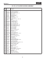
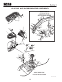
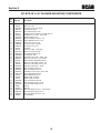
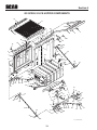
1
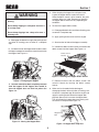
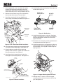
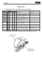
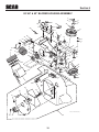
OPERATOR’S
MANUAL
CLAM SHELL
GRASS CATCHER
Models:
GC-SCZ48/52-CS
This manual contains the operating instructions and safety information for your
Scag mower accessory. Reading this manual can provide you with assistance
in maintenance and adjustment procedures to keep your mower accessory
performing to maximum efficiency. The specific models that this book covers
are listed on the inside cover. Before operating your machine, please read all
the information enclosed.
© 2013
Scag Power Equipment
Division of Metalcraft of Mayville, Inc.
PART NO. 03341
PRINTED 1/2013
PRINTED IN USA
WARNING
FAILURE TO FOLLOW SAFE OPERATING PRACTICES MAY RESULT IN
SERIOUS INJURY OR DEATH.
• Read this manual completely as well as other manuals that came with your mower.
• DO NOT operate on steep slopes. To check a slope, attempt to back up it (with the
cutter deck down). If the machine can back up the slope without the wheels slipping,
reduce speed and use extreme caution.
• Under no circumstances should the machine be operated on slopes greater than 15
degrees. ALWAYS FOLLOW OSHA APPROVED OPERATION.
• DO NOT mow on wet grass. Wet grass reduces traction and steering control.
• Keep all shields in place, especially the grass discharge chute.
• Before performing any maintenance or service, stop the machine and remove the
spark plug wire and ignition key.
• If a mechanism becomes clogged, stop the engine before cleaning.
• Keep hands, feet and clothing away from power-driven parts.
• Keep others off the mower (only one person at a time)
REMEMBER - YOUR MOWER IS ONLY AS SAFE AS THE OPERATOR!
Hazard control and accident prevention are dependent upon the awareness,
concern, prudence, and proper training of the personnel involved in the
operation, transport, maintenance, and storage of the equipment.
This manual covers the operating instructions and illustrated parts list for:
GC-SCZ48/52-CS
with a serial number of
J2900001 to J2999999
Always use the entire serial number listed on the serial number tag when referring to this product.
Section 1
R
GENERAL INFORMATION
1.1 Introduction
A replacement manual is available from your authorized
Scag Service Dealer or by contacting: Scag Power
Equipment, Service Department at P.O. Box 152, Mayville,
WI 53050. You may also contact us through our website at
www.scag.com The manual for this grass catcher can be
downloaded by using the model and serial number or use
the contact form to make your request. Please indicate the
complete model and serial number of your Scag product
when requesting replacement manuals.
This manual has been prepared to provide the information you need to correctly assemble, operate, and
maintain this grass catcher. Read it carefully and keep it
for future reference.
THE REPLACEMENT OF ANY PART ON THIS PRODUCT
BY OTHER THAN THE MANUFACTURER'S AUTHORIZED
REPLACEMENT PART MAY ADVERSELY AFFECT THE
PERFORMANCE, DURABILITY OR SAFETY OF THIS
PRODUCT.
WARNING
USE OF OTHER THAN ORIGINAL SCAG REPLACEMENT
PARTS WILL VOID THE WARRANTY.
Do not operate without discharge chute, mulch
kit, operator controlled discharge chute (OCDC),
or entire grass catcher installed.
If additional information or service is needed that is not
outlined in this manual, please contact your Scag Power
Equipment dealer. Scag dealers are trained in the latest
service methods and carry a full line of Scag replacement
parts.
2. Before removing the grass bags, disengage the
mower, stop the engine and wait for all movement to
stop.
When ordering parts, always provide the complete model
number and serial number of your catcher.
3. ALWAYS turn the engine OFF, remove the key and
wait for all movement to stop before servicing or
cleaning the mower or the grass catcher.
All information provided in this manual is based upon
information available at the time of printing. Scag Power
Equipment reserves the right to make changes at any time
without notice or obligation.
DANGER
ROTATING BLOWER
BLADES
1.2 Direction Reference
STOP ENGINE BEFORE
ENTERING CHUTE
The “Right” and “Left”, “Front” and “Rear” of the machine are
referenced from the operator’s right and left when seated
in the normal operating position and facing the forward
travel direction.
CONTACT CAN INJURE
4. Do not modify or alter any component of the grass
catcher attachment or mower.
1.3 SAFETY AND OPERATING
INSTRUCTIONS
5. Do not allow any passengers to ride on the grass
catcher attachment or on the mower.
1.4 GRASS CATCHER OPERATION
note To avoid personal injury, it is imperative that all
safety instructions be observed.
1. With the hopper door closed, engage the deck drive.
2. Proceed to mow until the hopper is full.
1. Read this operator's manual and the operator's
manual that is supplied with the machine this
attachment is used on.
3. When dumping the hopper into a disposal area:
1
Section 1
R
4. When dumping the hopper into a disposal area,
inspect the hopper debris screen for material.
When the debris screen is full of material, the grass
catching ability may suffer. Frequency of cleaning
the hopper debris screen will vary depending on
conditions.
WARNING
Do not dump clippings in a disposal area that is
burning.
Do not dump clippings in a disposal area that is
on a steep slope.
5. To clean the hopper debris screen;
A. Disengage the deck drive and allow all moving parts
to come to a complete stop.
Do not dump clippings into a drop off or over a
retaining wall.
B. Apply parking brake and shut off the engine.
A. Disengage the deck drive, apply the parking brake
and allow all moving parts to come to a complete
stop.
C. Stand on the left side of the hopper assembly.
D. Unhook the debris screen latches and remove the
debris screen from the hopper. See Figure 1-3.
B. Pull downward on the hopper door handle to allow
the hopper sweeper to remove the material from inside
the hopper. See Figure 1-1.
Debris Screen
Latches
Figure 2-3 GC-CS
Figure 1-3. Cleaning the Hopper Debris Screen
2007 Figure 2-1 GC-CS
Figure 1-1. Dumping the Hopper
E. Remove material from the debris screen and
reinstall. Secure by latching the debris screen
latches.
C.Once the material has been completely removed
from the hopper, lift the hopper door handle to
close the hopper door and lock into place. See
Figure 1-2.
6. When service is needed inside the hopper,
disengage the deck drive and allow all moving parts
to come to a complete stop. Shut off the engine and
apply the parking brake. Rotate the hopper door
prop rod upward until it contacts the hopper door.
This will prevent the hopper door from moving until
the service is complete. See Figure 1-4.
Hopper Prop
Rod
2007 Figure 2-2 GC-CS
Figure 1-2. Closing the Hopper Door
Figure 2-4 GC-CS
Figure 1-4. Hopper Door Prop Rod
2
Section 2
R
2.1 ASSEMBLY INSTRUCTIONS
4. Install the grass catcher pulley onto the spindle
assembly. Apply loctite to both pulley setscrews and
tighten. See Figure 2-1.
- note -
5. Remove the "Turbo" baffle from the cutter deck.
Using the original hardware, install the new "Turbo"
baffle. Install the baffle weldment. See Figure 2-2.
Use the illustrated parts list as a part number
r e fe r e n c e w h e n fo l l ow i n g t h e a s s e m bl y
instructions.
1. Remove all packaging materials. Lay out the
mounting hardware and the catcher assembly parts
for easy access. Prepare the work area making sure
that it is a clean, safe environment.
UNDER SIDE OF
VELOCITY-PLUS
Custom Cut Baffle
CUTTER DECK SHOWN
WARNING
Baffle Weldment
48V & 52V - 452383
Do not operate without discharge chute, mulch
kit, operator controlled discharge chute (OCDC),
or entire grass catcher installed.
Turbo Baffle
48V - 424683
52V - 424211
2. Remove the discharge chute from the cutter deck.
See Figure 2-1.
Figure 2-2. Grass Catcher Baffles
- note -
- note -
Do not discard the discharge chute or mounting
hardware. The discharge chute MUST be
reinstalled any time the grass catcher has been
removed from the machine.
Do not discard the original "Turbo" baffle. This
baffle may be reinstalled any time the grass catcher
has been removed from the machine.
3. Remove the right side belt cover to gain access to
the spindle assembly. Remove the front u-nut from
the cutter deck bracket. See Figure 2-1.
6. Install the blower mounting bracket to the
deck using carriage bolts (p/n 04003-11),
lockwashers, and nuts. Do not fully tighten
the hardware at this time. See Figure 2-3.
- note Retain the original belt cover. This cover MUST be
reinstalled any time the complete catcher system
is removed.
REMOVE DISCHARGE
CHUTE AND
HARDWARE
FLATWASHER
INSTALL PULLEY
ON RH SPINDLE SHAFT ON TOP OF EXISTING
SPINDLE DRIVE
REMOVE EXISTING
PULLEY
RT. SIDE BELT
COVER
ELASTIC STOP
NUT
CARRIAGE BOLT
REMOVE (2)
U-NUTS
RIGHT SIDE OF 61"
CUTTER DECK SHOWN
(Note: Some parts not shown for viewing purposes.)
Figure 2-3. Blower Mounting Post Installation
Figure 2-1. Discharge Chute Removal
3
Section 2
R
7. Units equipped with a 48" cutter deck will need to
have the right hand front cutter deck hang chain
replaced with the brackets included with this grass
catcher accessory. For 52" units, proceed to step 10.
13. Install the belt to the spindle pulley. When replacing
the belt. See Figure 2-6.
BACK SIDE
IDLER PULLEY
8. Remove the cutter deck hang chain and hardware
from the right front corner of the cutter deck.
BLOWER
PULLEY
9. Install the cutter deck lift link (p/n 426025) and
secure using the hardware provided. See Figure 2-4.
3/8” Flatwasher
FRONT SIDE
IDLER PULLEY
Bolt 3/8-16
x 1-3/4
SPINDLE
PULLEY
Figure 2-6. Belt Routing
Cutter Deck
Lift Link
Bolt 3/8-16 x 1
-1/2”Grade 8
14. Install the new belt covers and secure. See items
number 1 and number 21 on page 12 of the Blower
Mounting Components section in this manual for
proper installation.
Spacer
15. Remove the rear skid plate mounting hardware from
the outside two holes. See Figure 2-7.
Figure 2-4. 48" Cutter Deck Bracket Installation
16. Install the mounting pins and spacers on to the rear
of the machine. Secure using EIGHT (8) 3/8-16 x 1"
hex head bolts, and six (6) 3/8-16 elastic stop nuts.
See Figure 2-8.
10. Install the blower assembly to the mounting bracket
and secure with the mounting pin. See Figure 2-5.
11. Align the blower assembly with the discharge
opening of the cutter deck. Tighten the hardware for
the mounting bracket. See Figure 2-5.
12. Install the quick pin through the rear hole in the
discharge chute mounting bracket. See Figure 2-5.
BLOWER
ASSEMBLY
QUICK
PIN
HAIR
PIN
MOUNTING
BRACKET
MOUNTING PIN
TIGHTEN MOUNTING
BRACKET HARDWARE
Figure 2-7. Hopper Mounting Hardware Install
RIGHT SIDE OF
CUTTER DECK SHOWN
17. With help from an assistant, install the hopper
assembly to the machine and secure with the ring
pins. See Figure 2-8.
(Note: Some parts not shown for viewing purposes.)
2006 GC-STC-V install art 3
Figure 2-5. Blower Installation
4
Section 2
R
Figure 2-8. Hopper Instllation
18. Install the hose from the blower assembly adapter to
the hopper hood and secure using the 8-5/8" clamps.
19. Using the weight support bar as a guide, identify the
two corresponding mounting holes, and the existing
hardware that will need to be removed in order to
secure the weight support bar to the front of the
machine as shown. See Figure 2-9.
20. Install one 7/16-14 x 1-3/4" hex head bolt into each
of the two mounting holes in the weight support
bar, and through the matching holes in the caster
support weldment. Secure this assembly to the
front of the machine using the 7/16- .5" x 1-1/4" x
.083" flatwashers, and the 7/16-14 elastic stop nuts.
Torque hardware to 59 ft. lbs. See Figure 2-9.
Figure 2-9. Weight Support Bar Install
21. Install weights onto weight bar.
22. Operate and test.
5
Section 3
R
3.1 GRASS CATCHER REMOVAL
INSTRUCTIONS
WARNING
Prepare the machine so there is easy and safe access to
the work area. Park the machine on a flat, level surface
and apply the parking brake. Remove the ignition key
and disconnect the positive and negative cables from the
battery. Maintain all safety related work procedures. Always
wear hand and eye protection.
Do not operate without discharge chute, mulch
kit, operator controlled discharge chute (OCDC),
or entire grass catcher installed.
5. Re-install the side discharge chute to the opening
on the cutter deck. Replace the two (2) outside
mounting bolts on the discharge chute with the clevis
pins (p/n 04064-15) and rue cotter pins (p/n 0406903). See Figure 3-2.
- note For best overall performance and dispersal of
grass clippings while side discharging, the grass
catcher discharge baffle should be removed and
the original turbo baffle should be reinstalled.
6. Re-install the cutter deck belt cover.
7. Remove the weights from the weight bar.
1. Remove the rubber strap holding the adapter to the
blower assembly and the large quick pin securing
the blower to the discharge mounting bracket. See
Figure 3-1.
DISCHARGE
CHUTE
2. Remove the belt, pin, hair pin and large quick pin
securing the blower assembly to the cutter deck and
remove the blower assembly. See Figure 3-1.
CLEVIS PIN
P/N 04064-15
ADAPTER
BLOWER
ASSEMBLY
CLEVIS PIN
P/N 04064-15
GC-STC-V removal art 3
QUICK PIN
RUE COTTER PIN
P/N 04069-03
Figure 3-2. Reinstalling the Discharge Chute
PIN & HAIR PIN
MOUNTING
BRACKET
RIGHT SIDE OF
CUTTER DECK SHOWN
2006 GC-STC-V removal art 1
(Note: Some parts not shown for viewing purposes.)
Figure 3-1. Removing the Blower Assembly
3. Remove the ring pins securing the hopper assembly
to the rear of the machine.
4. With help from an assistant, remove the hopper
assembly.
6
Section 4
R
MAINTENANCE
4.1 MAINTENANCE CHART - RECOMMENDED SERVICE INTERVALS
HOURS
Break-In 8 20 40 100 200 500 Procedure
(First 10)
Comments
X
Check all hardware for tightness
X
Inspect hose and adapter
X
Check belt for proper alignment
X
Inspect fabric bags
X
*Check screen in hopper
X
Inspect hose and adapter
X
Inspect fabric bags
X
Check condition of blower
X
*Apply grease to blower bearings
X
Remove debris from screen
See figure below
Check belt for proper alignment
* Perform these maintenance procedures more frequently under extreme dusty or dirty conditions.
GREASE FITTING
ON BEARING HOUSING
GREASE FITTING
ON BEARING HOUSING
BEHIND PULLEY
Section 5
R
ILLUSTRATED PARTS LIST
4.1 SCAG APPROVED ATTACHMENTS AND ACCESSORIES.
Attachments and accessories manufactured by companies other than Scag Power Equipment are not approved
for use on this machine.
8
Section 5
R
NOTES
9
Section 5
R
GC 48" & 52" BLOWER HOUSING ASSEMBLY
9
10
8
4
48
1
2
11
12
49
14
50
13
11
9
12
27
11
7
10
47 10
44
14
14
11
15
43
16
42
52
39
51
40
14
18
A
W
FO
E
B
R E
E IN
v HL
O C UA
C MAAN
M
LT 'S
E GR
B TINATO
R
LL RAOPE
TA E D
S PREA
IN O
IN
N
R
G
34
17
26
41
E
R
3
25
28
20
41
38
17
35
15
17
19
21
22
27
23
5
24
46
14
DA
L g
B vin
D mo
N re
A or ER R
S g W O ED
E nin O R LL
D lea M HE TA
A c TE C S
L re RA AT IN
B befo PE S C D IS
O AS R
e
A
in T
g O GR U
en O N S E G
D ES G
L R
N A
U H
C
IS
D
24
ER
R
14
29
ER
NG
DA
E
INJURE
CONTACT
W
O
CHUTE
ENTERING
CAN
G
p
to
BEFORE
ENGINE
IN
S
BLOWER
ROTATING
BLADES
STOP
NG
T
A
T
O
R
GER
DAN
ER
OW
BL
RE
ING ES
FO E
TAT BLAD
RO
E BE UT
E
GING CH
UR
P ENRIN
N INJ
STOENTE
CA
CT
NTA
CO
6
30
33
32
37
31
31
45
47
2013 GC V+ Blower Assembly
35
34
45
36
10
Section 5
R
GC 48" & 52" BLOWER HOUSING ASSEMBLY
Ref.
No.
1
2
3
4
5
6
7
8
9
10
11
12
13
14
15
16
17
18
19
20
21
22
23
24
25
26
27
28
29
30
31
32
33
34
35
36
37
38
39
40
41
42
43
44
45
46
47
48
49
50
51
52
Part No.
04067-07
481547
04019-02
04019-02
483392
483393
481428
483223
04024-02
04021-05
04041-07
43277
483173
04021-09
04030-04
424361
04003-05
04001-54
04001-81
04001-21
461939
483327
484728
483189
04043-04
43503
483402
04019-04
04001-136
483391
461931
04003-12
04063-06
461796
483034
04021-10
461930
421319
48136-02
462536
482298
04012-04
462553
481522
43212
04019-03
461723
451821
04062-04
424367
424367
48135-16
48028-11
Description
Pin, Ring 2-1/4" Long
Lanyard, Deck Height Pin
Nut, Serr. Flange 1/4-20
Bolt, Hex Head 1/4-20 x 1-1/4"
Decal, Blower
Decal, Rotating Blower
Grip, Blower Lever
Cap, Square
Nut, Push On 3/8 Thread
Lock Nut, 3/8-16
Flatwasher, 3/8-.391 x .938 x .105
Spacer
Pulley, Idler 3-1/2" Dia.
Nut, Elastic Stop 3/8-16
Lockwasher, 3/8-16
Plate, Catcher Mounting
Bolt, Carr. 3/8-16 x 1-1/2"
Bolt, Hex Head 3/8-16 x 3" - 52"
Bolt, Hex Head 3/8-16 x 3-1/2"
Bolt, Hex Head 3/8-16 x 1-3/4"
Idler Arm Assembly
Belt, GC-SCZ-48V
Belt, GC-SCZ-52V
Pulley, 3-1/2" O.D., GC-STC
Washer, 3/8 Hardened
Pivot, Idler
Decal, Belt Cover
Nut, Serr. Flange 3/8-16
Bolt, Hex Head 3/8-16 x 1-1/2 Gr. 8
Decal, Danger
Blower Housing Weldment
Bolt, Carr. 5/16-18 x 3/4" Gr. 5
Key, 1/4 x 1/4 x 1-1/2"
Fan Weldment
Bearing Assembly
Nut, Elastic Stop 5/16-18
Blower Housing Assembly, GC-STT
Cover, Blower Housing
Clamp, 8-5/8" Max Dia.
Hose, 8.00" Dia. x 53" Long (incl. #51, 52)
Pulley, 4-3/4" O.D. - 1" Bore
Set Screw, 5/16-18 x 3/8"
Frame, Blower Mount
Spring, Main Drive
Spacer
Nut, Serr. Flange 5/16-18
Adapter w/Strap
Receiver Weldment, Mounting Post
Hair Pin Cotter, .177 x 3-1/4"
Dust Shield
Quick Pin, 5/16" Dia.
Hose, 8" Dia. x 24" Split
Cable Tie, .345 X 31.5 Black
11
Section 5
R
GC-SCZ 48" & 52" BLOWER MOUNTING COMPONENTS
UNDER SIDE OF
vELOCITY-PLUS
CUTTER DECK SHOWN
10
11
16
10
16
23
5
27
2
4
6
1
26
25
7
8
26
25
23
3
28
6
12
24
25
13
22
9
37
21
14
15
20
15
19
29
16
17
18
30
18
31
34
35
32
33
36
RIGHT SIDE OF 48”
CUTTER DECK SHOWN
2013 GC-STC-V BMC
12
Section 5
R
GC-SCZ 48" & 52" BLOWER MOUNTING COMPONENTS
Ref.
No.
1
2
3
4
5
6
7
8
9
10
11
12
13
14
15
16
17
18
19
20
21
22
23
24
25
26
27
28
29
30
31
32
33
34
35
36
37
Part No.
484679
484685
04029-04
483223
04021-08
461723
04040-14
48137-04
04001-59
481625-01
04064-15
04069-03
04067-07
481547
482587
04012-04
04021-09
04030-04
04041-07
04003-11
461894
462549
462550
04029-04
04003-23
04001-09
04040-15
04021-10
452383
424683
424211
04024-02
04003-22
04019-04
43606
452393
04001-136
04019-04
04001-21
484368
Description
Belt Cover, 48"
Belt Cover, 52"
Wingnut, Plastic 3/8" Small
Cap, Square Vinyl
Nut, Elastic Stop 1/4-20
Adapter, Blower GC-STC, includes item #7
Flatwasher, 1/4-.312 x .750 x .065
Rubber Strap 7-3/4"
Bolt, Hex Head 1/4-20 x 1-1/4"
Knob W/Stud, 3/8-16 x 1-1/4"
Clevis Pin, 5/16 x 1-1/2"
Pin, Rue Cotter 5/16 Dia.
Pin, Ring 1/2 x 2-1/4"
Lanyard
Pulley, 4.0" Dia. 1.125 Bore
Setscrew, 5/16-18 x 3/8"
Nut, Elastic Stop 3/8-16
Lockwasher, 3/8"
Flatwasher, 3/8-.391 x .938 x .105
Bolt, Carr. 3/8-16 x 1-1/4" Grade 5
Mounting Post Weldment, Blower
Belt Cover Assembly, w/Cap - 48"
Belt Cover Assembly, w/Cap - 52"
Wing Nut, 3/8 Plastic - Small
Bolt, Carriage 3/8-16 x 1"
Bolt, Hex Head 5/16-18 x 1"
Flatwasher, 5/16-.375 x .875 x .083
Nut, Elastic Stop 5/16-18
Baffle Weldment 48 / 52
Baffle, Turbo 48" Deck
Baffle, Turbo 52" Deck
Nut, Push-On 3/8 Thread
Bolt, Carriage 3/8-16 x 1-1/4"
Nut, Serrated Flange 3/8-16
Sleeve
Bracket
Bolt, Hex Head 3/8-16 x 1-.40" Grade 8
Nut, Serrated Flange 3/8-16
Bolt, Hex Head 3/8-16 x 1-3/4"
Cap, Spindle
13
Section 5
R
GC-SCZ48 / 52-CS HOPPER COMPONENTS
16
14
49
50
45
41
15
31
43
56
55
51
17
39
12
9
6
25
34
49 53
50
B
49
55
6
11
40
58
59
8
2
5
4
3
45
29
34
24
42
49
53
27
43
38
48
37
57
18
C
49
34
49
50
52
54
41
12 18
53
24
49
58
59 28
57
38
62
34
49
21
A
7
1
49
10
33
49
45
32
50
30
20
47
25
23
40
58
44
22
13
44
B
32
59
35
37
C
26
49
46
A
19
46 49 58 59
29
38
46
35
37
46
28
38
57
49
49
26
37
57
2013 CSHOPPEREXPLODE
14
Section 5
R
GC-SCZ48 / 52-CS HOPPER COMPONENTS
Ref.
No.
Part No.
Description
1
2
3
4
5
6
7
8
9
10
11
12
13
14
15
16
17
18
19
20
21
22
23
24
25
26
27
28
29
30
31
32
33
34
35
36
37
483038
482732
461626
482777
04090-02
423834
426019
423849
423850
425802
423837
423840
451980
451601
451602
451603
451607
43631
04001-12
04012-10
44185
423836
424405
424406
43063
43282
43277
481309
43641
43640
481245
04001-10
04001-18
423855
423859
04001-20
04001-21
423865
04001-45
Hopper, GC-STT-CS
Door, GC-CS
Sweeper Weldment, GC-CS
Pad, Rubber
Pop Rivet, 3/16 x .652
Plate, Stiffener
Support Frame, Hopper
Hinge Bracket, LH
Hinge Bracket, RH
Mounting Bracket, Dump Handle Latch
Latch, Door Prop
Plate, Latch
Bellcrank Weldment, Upper
Debris Screen Weldment
Screen Support Weldment, Rear
Screen Support Weldment, Front
Hinge Weldment, Hopper
Spacer
Bolt, Hex Head 5/16-18 x 1-3/4"
Nut, 5/16-18 Elastic Stop (Not Shown)
Rod, Dump Lever GC-SCZ-CS
Retainer Strip, Hopper
Latch, Dump Rod Inner
Latch, Dump Rod Outer
Spacer
Spacer
Spacer
Latch, Hood
Linkage Assembly, Lower
Linkage Assembly, Upper
Knob
Bolt, Hex Head 5/16-18 x 1-1/4"
Bolt, Hex Head 3/8-16 x 3/4"
Bracket, Lower Stiffener
Backing Plate, Hopper (Not Shown)
Bolt, Hex Head 3/8-16 x 1-1/2"
Bolt, Hex Head 3/8-16 x 1-3/4"
Alignment Bracket, GC-CS
Bolt, Hex Head 3/8-16 x 2"
15
Ref.
No.
Part No.
Description
38
39
40
41
42
43
44
45
46
47
48
49
50
51
52
53
54
55
56
57
58
59
04020-25
04001-63
04001-77
04003-04
04010-01
04017-16
04017-17
04019-03
04019-04
04020-12
04021-01
04021-09
04021-10
04032-01
04040-15
04041-07
43642
04001-54
451598
481539
481538
04020-26
Nut, 3/8-24 UNF RH Thread
Bolt, Hex Head 5/16-18 x 3-1/2"
Bolt, Hex Head 3/8-16 x 3-1/2"
Bolt, Carriage 5/16-18 x 1"
Screw, #10-32 x 1/2"
Cap Screw, 5/16-18 x 3/4" Serr. Flan.
Cap Screw, 5/16-18 x 1" Serr. Flan.
Nut, 5/16-18 Serrated Flange
Nut, 3/8-16 Serrated Flange
Nut, 3/8-16 UNC Jam
Nut, #10-32 Elastic Stop
Nut, 3/8-16 Elastic Stop
Nut, 5/16-18 Elastic Stop
Washer, Special Wave
Washer, 5/16-.375 x .875 x .083 Flat
Washer, 3/8-.931 x .938 x .105 Flat
Bushing, Hopper Latch GC-CS
Bolt, Hex Head 3/8-16 x 3"
Hinge Weldment, Door
Rod End Male, 3/8-24 RH Thread
Rod End Male, 3/8-24 LH Thread
Nut, 3/8-24 UNF LH Thread
Section 5
R
GC-SCZ48 / 52-CS HOPPER SUPPORT COMPONENTS
6
2
3
7
1
F
B
E
3
3
3
4
3
3
A
2
B
8
6
5
4
7
12
3
3
8
3
6
F
6
9
11
9
8
10
6
6
6
3
D
A
22
3
C
8
3
6
8
3
6
3
13
12
3
E
3
6
5
15
3
3
23
24
14
6
8
6
10
3
D
6
23
16
17
20
3
C
3
16
19
17
18
3
17
21
18
21
19
20
17
2013-SCZ4852 CS Hopper Support
16
Section 5
R
GC-SCZ48 / 52-CS HOPPER SUPPORT COMPONENTS
Ref.
No.
1
2
3
4
5
6
7
8
9
10
11
12
13
14
15
16
17
18
19
20
21
22
23
24
Part No.
426019
426020
04117-02
426021
422386
04001-19
04001-32
04001-46
04066-04
426012
452382
426015
426011
426010
426017
43884
04041-11
04030-04
04001-32
04001-46
43886
426016
426024
04003-22
Description
Support Frame, Hopper
Bracket, Hopper Support
Nut, Elastic Flange 3/8-16
Brace, Stiffener
Brace, Engine Mount
Bolt, Hex Head 3/8-16 x 1"
Bolt, Hex Head 3/8-16 x 1-1/4"
Bolt, Hex Head 3/8-16 x 2-1/4"
Quick Pin
Mounting Bracket, Tube
Mounting Bracket Weldment
Tube, Upright
Mounting Bracket, GC R.H.
Mounting Bracket, GC L.H.
Angle Bracket, GC
Pin, GC Locator
Flatwasher, 3/8-.406 x 1.50 x 7 Ga.
Lockwasher, 3/8"
Bolt, Hex Head 3/8-16 x 1-1/4"
Bolt, Hex Head 3/8-16 x 2-1/4"
Spacer
Angle Bracket, GC
Wear Plate, GC
Bolt, Carriage 3/8-16 x 1-1/4"
17
Section 5
R
FRONT WEIGHT COMPONENTS
1
5
4
4
3
2
18
5
Section 5
R
FRONT WEIGHT COMPONENTS
Ref.
No.
1
2
3
4
5
Part No.
9009
04001-117
452386
04040-11
04021-11
Description
Weight Assembly
Bolt, Hex Head 7/16-14 x 1-3/4"
Support Weldment, Weights
Flatwasher, 7/16-.500 x 1-1/4"
Nut, Elastic Stop 7/16-14
19
Section 5
R
GC-SCZ 48/52 DECALS
483402
482275
481327
483392
483392
483391
483391
483393
483393
20
LIMITED WARRANTY- COMMERCIAL ACCESSORY
Any part of the Scag commercial accessory manufactured by Scag and found, in the reasonable judgment of
Scag, to be defective in material or workmanship, will be repaired or replaced by an Authorized Scag Service
Dealer without charge for parts and labor.
The Scag accessory, including any defective part, must be returned to an Authorized Scag Service Dealer
within the warranty period. The expense of delivering the accessory to the dealer for warranty work and the
expense of returning it back to the owner after repair or replacement will be paid for by the owner. Scag’s
responsibility in respect to claims is limited to making the required repairs or replacements, and no claim of
breach of warranty shall be cause for cancellation or rescission of the contract of sale of any Scag machine.
Proof of purchase will be required by the dealer to substantiate any warranty claim. All warranty work must be
performed by an Authorized Scag Service Dealer.
This warranty is limited to 90 days from the date of original retail purchase for any Scag accessory that is used
for commercial purposes, or any other income-producing purpose including rental use.
The warranty for the grass catcher blower assemblies (excluding the belt) is limited to 1-year from the date of
original retail purchase. 90 Days for rental use.
This warranty does not cover any accessory that has been subject to misuse, neglect, negligence, or accident,
or that has been operated in any way contrary to the operating instructions as specified in the Operator's Manual.
The warranty does not apply to any damage to the accessory that is the result of improper maintenance, or to
any accessory or parts that have not been assembled or installed as specified in the Operator's Manual.
The warranty does not cover any accessory that has been altered or modified. In addition, the warranty does
not extend to repairs made necessary by normal wear, or by the use of parts or accessories which, in the
reasonable judgment of Scag, are either incompatible with the Scag mower or adversely affect its operation,
performance or durability. This warranty does not cover engines and electric starters, which are warranted
separately by their manufacturer.
Scag Power Equipment reserves the right to change or improve the design of any accessory without assuming
any obligation to modify any accessory previously manufactured.
All other implied warranties are limited in duration to the 90 day warranty period. Accordingly, any such implied
warranties including merchantability, fitness for a particular purpose, or otherwise, are disclaimed in their
entirety after the expiration of the appropriate ninety day warranty period. Scag’s obligation under this warranty
is strictly and exclusively limited to the repair or replacement of defective parts and Scag does not assume or
authorize anyone to assume for them any other obligation. Some states do not allow limitations on how long an
implied warranty lasts, so the above limitation may not apply to you.
Scag assumes no responsibility for incidental, consequential or other damages including, but not limited to,
expense for gasoline, oil, expense of delivering the machine to an Authorized Scag Service Dealer and expense
of returning it back to the owner, mechanic’s travel time, telephone or telegram charges, rental of a like product
during the time warranty repairs are being performed, travel, loss or damage to personal property, loss of
revenue, loss of use of the mower, loss of time, or inconvenience. Some states do not allow the exclusion or
limitation of incidental or consequential damages, so the above limitation or exclusion may not apply to you.
This warranty gives you specific legal rights, and you may also have other rights which vary from state to
state.