1
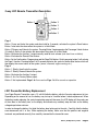
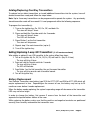
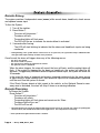
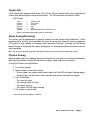
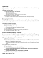
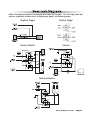
G777,G27
A777,A20
VEHICLE SECURITY SYSTEM
PRODUCT MANUAL
Limited Lifetime Warranty
This vehicle security system is warranted to the original purchaser, to be free from defects in
material and workmanship. The manufacturer will repair or replace at its option, and free of
charge for the first twelve (12) months, any part that proves defective in material or workmanship
under normal installation, use, and service, provided the product is returned to the manufacturer
freight prepaid. After the first 12 month of the warranty period there will be a maximum service
charge of $50.00 per calendar year (if required) for repair and/or replacement of any defective
parts.
A copy of the original purchase and installation receipt must accompany any products
returned for warranty service. Warranty is limited to defective parts and/or replacement parts
only and excludes any incidental, and consequential damages connected therewith.
The manufacturer of this theft deterrent system makes no warranty against the theft of the vehicle
or its contents. This warranty is not to be construed as an insurance policy against loss.
WARRANTY OF INSTALLATION LABOR, REMOVAL AND RE-INSTALLATION CHARGES ARE
NOT THE RESPONSIBILITY OF THE MANUFACTURER.
Note: This Warranty is voided if the product was not installed by an
Authorized ScyTek Dealer.
2-way LCD Remote Transmitter Description
Button 1
Button 2
Button 3
Button 4
Button 5
Page 1
Button 1 Arms and Locks the system and when held for 5 seconds, activates the system’s Panic feature.
Button 1 also locks the doors when the system is in Valet Mode.
Button 2 Disarms and Unlocks the system. Pressing Button 2 again operates the Passenger Unlock feature
(if installed). Button 2 also unlocks the doors when the system is in Valet Mode.
Button 3 Activates the Auxiliary 1 output normally used for trunk release (note trunk icon on button).
Button 4 Activates the Remote Start feature.
Button 5 is the Confirmation, Programming and the Page Shift button. Quickly pressing button 5 will activate
the Page 2 function. Pressing button 5 for 2 seconds activates the system’s confirmation feature which will
then display the current status of the system (armed, disarmed, engine running, etc.).
Page 2
Button 1 Silently Arms/Locks the system.
Button 2 Silently Disarms/Unlocks the system.
Button 3 Activates the Auxiliary 2 output.
Button 4 Aux 3 or Factory Rearm output.
Button 5 Not Implemented. Page 3 & 4 are used as Page 1 & 2 for second car operation
LCD Transmitter Battery Replacement
Your Pager Remote Transmitter uses a 1.5 volt AAA alkaline battery, which will require replacement in time.
Depending on the amount of use, the battery may last up to 3 months before it needs replacement. When
the battery needs replacing, the system’s operating range will decrease, the LCD display will show only one
of three bars in the battery icon, or the display and sounds may suddenly stop and start as the battery
voltage drops below minimum.
In order to change the battery, first slide the battery door locking pin to the side. Carefully slide the battery
cover downward until it is free. While replacing the battery make sure that the positive and negative
terminals are positioned correctly, then carefully reassemble the transmitter case.
A777, A20, G777, G27
Page 1
Remote Transmitters
Remote Transmitter Description
LED
Button 1
Button 2
LED
Button 1
Button 2
Button 4
Button 3
Button 5
Button 4
Button 3
G777,G27
Button 5
A777,A20
The G777,G27,A777,A20 is supplied with 5-button Remote Transmitter used to control system
operations.
Button 1 Arms and Locks* the system and when held for 5 seconds, activates the system’s Panic
feature. Button 1 also locks the doors when the system is in Valet Mode.
Button 2 Disarms and Unlocks* the system. Pressing Button 2 again operates the Passenger Unlock
feature (if installed). Button 2 also unlocks the doors when the system is in Valet Mode.
Button 3 Activates the Auxiliary 1 output. This output will remain on for as long as the button is
pressed.
Button 4 Activates the Auxiliary 2 output. This output will remain on for as long as the button is
pressed.
Button 5 is the Page Shift button. The Page Shift button will change the function of Buttons 1
through 4 each time it is pressed, allowing access to additional features or multiple car operation.
Each time the Shift Button is pressed, the LED on the transmitter will illuminate and the
transmitter functions will shift to the next page, allowing access to another set of features. Once
shifted to another page (there are 4 pages total), the transmitter will remain on that page for 10
seconds or until a button is pressed, then return to page 1. Each time a transmitter button is
pressed and held, the LED will flash a number of times to indicate from which page it is
transmitting. Under normal operation, only pages 1 and 2 are used. Pages 3 and 4 are usually
used for Two Car Operation.
Shift then Button 1 Arms and Locks* the system silently.
Shift then Button 2 Disarms and Unlocks* the system silently.
* If the Optional Keyless Entry Feature is installed.
Page 2 - A777, A20, G777, G27
Adding/Replacing One-Way Transmitters
To replace lost or stolen transmitters or to add additional transmitters into the system, have all
desired transmitters ready and follow the steps below.
Note: Up to 4 one-way transmitters can be programmed to operate the system. Any previously
stored transmitter code will be erased if it is not programed within the following sequence.
To program the transmitter(s):
1. Turn on the ignition key On, Off, On, Off, and back On.
· The siren will chirp 3 times.
2. Press and hold the Override switch for 5 seconds.
· The siren will chirp 5 times.
· The LED will illuminate.
3. Press Button 1 on the first transmitter.
· The siren will chirp once.
4. Repeat step 3 for each transmitter (up to 4).
5. Turn off the ignition key.
Adding/Replacing 2-way LCD Transmitters
(2 LCD remotes maximum)
When adding an optional 2-way LCD transmitter to the system, follow these steps:
1. Turn on the ignition key On, Off, On, Off, On, Off, and back On. (Key On 4 times)
· The siren will chirp 4 times.
2. Press and hold the Override switch for 5 seconds.
· The siren will chirp 4 times.
· The LED will illuminate.
3. Press Button 1 on the first transmitter, then on the second transmitter.
· The siren will chirp once for each transmitter learned.
4. Turn off the ignition key.
Battery Replacement
Your Remote Transmitter uses battery type 2016 for G777,G27 and 23A for A777,A20 which will
require replacement in time. Depending on the amount of use, the battery may last up to 24
months or more before it needs replacement.
When the battery needs replacing, the system’s operating range will decrease or the transmitter
LED may not be as bright.
In order to change the battery, first remove 2 screws from the back of the transmitter and
separate the top and bottom halves of the case.
While replacing the battery make sure that the positive and negative terminals are positioned
correctly, then carefully reassemble the transmitter case.
A777, A20, G777, G27
Page 3
System Operation
Remote Arming
The system monitors 4 independent areas (zones) while armed: doors, hood/trunk, shock sensor
and optional sensor input.
To Arm the System:
1. Turn off the ignition.
2. Press Button 1.
· The siren will chirp once.*
· The doors will lock.
· The parking lights will flash once.
· The LED will turn on, to indicate the starter defeat is activated.
3. 5 seconds after Arming:
· The LED will start blinking to indicate that the doors and hood/trunk inputs are being
monitored.
* During Arming, if the system detects a bad sensor or an open zone, the system will chirp 4 additional times
and ignore that input, but keep all other areas protected.
Once Armed, the alarm will trigger when any of the following occurs:
· The doors are opened.
· The hood or trunk is opened.
· The shock sensor detects an impact to the vehicle.
· The optional sensor is disturbed.
When the alarm triggers, the siren will sound, the horn will honk, and the parking lights will
flash. If the system is triggered by the doors, or hood/trunk, the system will alarm for 45
seconds. If triggered by the shock sensor or optional sensor input, the system will alarm for
30 seconds.
In the event the alarm is triggered and remains triggered continuously by the same sensor
or input during a single arming cycle, that sensor or input will be automatically bypassed
until the next time the system is armed.
If the Shock Sensor detects a light impact to the vehicle, or the Optional Sensor’s warnaway zone is disturbed, the siren will chirp 5 times as a warning indication.
Remote Disarming
To Disarm the System:
Press Button 2
· The siren will chirp twice.*
· The doors will unlock.
· The parking lights will flash twice and remain on for 30sec..
· The dome light will turn on.**
· The LED will turn off.
* During Disarming, if the system was triggered while away from the vehicle, the siren will chirp 3 times, the parking lights
will flash 3 times, and the LED will flash to indicate triggered zone. See Tamper Alert for zone listing.
** If the optional Dome Light Activation Feature is installed.
Page 4 - A777, A20, G777, G27
Tamper Alert
If the system was triggered while away, the LED will flash to indicate which zone triggered the
system after disarming and turning on the ignition. The LED indication will repeat 8 times.
LED Flashes:
1 flash
2 flashes
3 flashes
4 flashes
5 flashes
10 flashes
=
=
=
=
=
=
optional sensor
shock sensor
not used
door
trunk
main power interrupt or system was reset
example: flash-flash-pause-flash-flash-pause = shock sensor
Silent Arming/Disarming
The system can be programmed to operate without Arm and Disarm chirp indications. When
programmed for full-time silent operation, the siren will sound only when the system is triggered.
The system is also capable of temporary silent operation if desired. Pressing the Shift button
before Arming or Disarming the system will bypass the chirp confirmations and allow one-time
silent operation.
Note: The open zone warning chirps will not be bypassed when the system is Armed or Disarmed silently.
Passive Arming
When programmed for the optional Passive Arming feature, the system arms itself automatically,
each time the ignition is turned off and all of the doors, hood, and trunk are closed.
To start the Passive Arming Process:
1. Turn off the ignition.
2. Open the door and exit the vehicle.
· Once all doors are closed and the dome light is off, the LED will begin flashing rapidly.
Parking Lights will flash twice three seconds after passive arming cycle began.
3. After 30 seconds,
· The siren will chirp.
· The parking lights will flash.
· The doors will lock.*
· The status LED will begin flashing.
4. The system is now armed.
* If the Passive Locking feature is selected.
A777, A20, G777, G27
Page 5
Panic Mode
In the event of an emergency, the transmitter’s remote Panic feature can be used to instantly
trigger the alarm.
To activate the Panic Mode:
1. Press and hold Button 1 for 5 seconds.
· The alarm will sound.
· The parking lights will flash.
· The doors will unlock* allowing access to the vehicle.
2. Press Button 2 to stop Panic Mode.
* If the ignition is on when the Panic feature is activated, the doors will lock for personal safety.
Emergency Override
If the transmitter becomes lost or inoperable, the system can still be disarmed using the following
procedure. Before beginning this procedure be sure to have the ignition key ready and know the
location of the override switch.
To Emergency Override the system:
1. Unlock the door using the key.
2. Enter the vehicle.
· The system will trigger and the siren will sound.
3. Turn the ignition key on.
4. Press and hold the override switch until the system disarms.
5. The vehicle will now be able to start.
Optional Coded Emergency Override
As an extra measure of security, the system is equipped with an optional Coded Emergency
Override feature. Once an Emergency Override Code is chosen and programmed during
installation, the system can no longer be disarmed using the standard override procedure.
To Emergency Override the system using the Code:
1. Follow steps 1-3 above.
2. Press the override switch a number of times equal to the Disarm code, and continue
holding for 10 seconds on the last press.
· The system will disarm. If the code is entered incorrectly, turn off the ignition and begin
again.
To set the Emergency Override Code:
1. Turn on ignition.
2. Within 5 seconds, press the valet switch 5 times.
· The siren will provide one long chirp, indicating that you have entered Programming.
3. Press the valet switch 4 times.
· The siren will chirp each time the valet switch is pressed.
4. Within 5 seconds, press Button 3 on the transmitter.
Page 6 - A777, A20, G777, G27
System Programming
Entering System Programming
To enter System Programming:
1. Turn on ignition.
2. Within 5 seconds, press the valet switch 5 times.
· The siren will provide three chirps, indicating that you have entered Programming.
3. Press the valet switch the number times equal to the System Option you want to change.
· The siren will chirp each time the valet switch is pressed.
4. Within 5 seconds, press the transmitter button corresponding to the desired operating mode for
that System Option.
· The siren will chirp to indicate the setting.
1 chirp
=
Button 1
2 chirps
=
Button 2
3 chirps
=
Button 3
5. When you are finished, turn off the ignition to save the changes.
Default Reset
Following this procedure will set all Programmable System Options to factory default settings.
1. Enter System Programming.
2. Press Transmitter Button 3.
· The siren will chirp 6 times indicating that the reset signal was received.
· All Programmable System Options are now set to factory default settings.
· The Valet Mode is off.
3. Turn off ignition.
Programmable System Options
The following is a description of the programming options. Some program branches control more than one
option, and may require accessing a particular branch number twice in order to program all desired features.
1. Horn Chirps with Arm & Disarm. Selects one of two modes: Normal, Horn Chirps
Normal. When selected, the horn will honk only when the alarm is triggered.
Horn Chirps. When selected, the horn will provide the arm/disarmed trigger indications, allowing the siren
installation to be skipped.
2. Arm Mode. Selects one of two modes: Manual Arming or Passive Arming.
3. Passive Door Locking. Selects whether or not the system will automatically lock the doors during
Passive Arming.
4. Ignition Controlled Locks/ Override Code Set. This dual program branch sets Ignition Controlled
Locking and programs the optional Emergency Override Code. If Lock Only is selected, the doors will not
automatically unlock when the ignition is turned off.
Override Code Set. Changes the Emergency Override Code for a higher level of security (see page 7).
5. Ignition Door Unlocking. Selects whether or not the system automatically unlocks the doors when the
ignition is turned off. The Ignition Door Locking feature may be programmed to unlock all doors or the
driver’s door only. If driver’s door only is selected, the optional Passenger Unlock feature must be
connected. (See Two Stage Door Lock Diagrams)
A777, A20, G777, G27
Page 7
6. Ignore Open Door Report. Bypasses the open zone warning chirps for vehicles equipped with a
residual dome light circuit that remains ON for a period of time after closing the door.
7. Auto Rearming Mode. When selected, the system will automatically re-arm and lock 30 seconds after it
has been disarmed regardless if a door is open or closed.
8. Door Unlock Pulse. Selects between one pulse or two pulse operation for the door unlock output.
Vehicles that require two pulses on the proper wire to unlock the doors can be interfaced directly without
9. Warn-Away Pager Report. When Enabled, Warn-Away report will be sent to the pager. If Disabled no
Warn-Away report will be sent to the pager.
10. Disarm with Auxiliary 1. When selected, activating the Auxiliary 1 output (usually used to open the trunk)
will disarm the alarm.
11. Door Lock Pulse Length. Selects between a 1, 3 or 0.1 second output for door locking and unlocking.
the use of relays or any additional circuitry by programming the system for double unlock pulse. Program
to 3 seconds for vehicles equipped with vacuum door locking systems.
12. Anti-Carjack Type. Selects one of three modes for Anti-Carjacking: Active, Passive, or Full-Time.
Manual. When selected, pressing Button 4 will automatically engage the Anti-Carjacking feature.
Passive. When selected, the Anti-Carjacking feature will activate whenever a door is opened while the
ignition is on.Full-Time. When selected, the Anti-Carjacking feature will automatically activate each time
the ignition is turned on.
13. Anti-Carjack Mode. Enables Anti-Carjacking protection.
14. Horn Honk Output. Selects the output, when activated, to be pulsing or constant.
15. Aux 2 Auto Activate with Arm. When selected, the Auxiliary 2 output will activate when the system is
armed. This feature can be used to roll-up windows, close sunroofs, activate accessories, etc.
16. Auxiliary 1 Mode. Selects from momentary, 10 second timed, or latched operation for Auxiliary 1.
Momentary operation provides an output for as long as the transmitter button is pressed.
Timed operation provides an output that turns on for 10 seconds each time the transmitter button is
Latched operation provides an output that turns on when the transmitter button is pressed and remains
on until the transmitter button is pressed again.
17. Auxiliary 2 Mode. Selects from momentary, 10 second timed, or latched operation for Auxiliary 2.
Momentary operation provides an output for as long as the transmitter button is pressed.pressed. If the
button is pressed again during the 30 seconds, the output will turn off.
Timed operation provides an output that turns on for 10 seconds each time the transmitter button is
pressed. If the button is pressed again during the 30 seconds, the output will turn off.
Latched operation provides an output that turns on when the transmitter button is pressed and remains
on until the transmitter button is pressed again.
18. Auxillary 2 Output Selectable. Selects either Auxillary 2 output, starter output or ignition output.
19. Extended Parking Lights. When selected, the parking lights will remain ON for 30 seconds after
disarming the system.
Page 8 - A777, A20, G777, G27
20. Data Bus Input Triggers. When enabled, the system will read all available triggers from the bypass
module. If disabled the system triggers must be hardwired.
21. Data Bus Interface Mode. Selects between iData, Fortin, or Fortin RF kit bypass modules.
22. Starter Confirmation Chirps. When enabled system chirps before remote stater activated, when
disabled, no chirps will sound upon remote start.
23. Lock After Start. this dual program branch selects lock after start, and enables push to start.
The doors will automatically lock after remote starting.
Push to Start enable, when selected.
24. Lock After Shutdown. this dual program branch selects unlock after shutdown, and disables push to
start.
Unlock after Shutdown ,when selected On, the doors will automatically unlock after engine shutdown.
Push to Start disable, when selected.
25. Unlock Before Start. when enabled, system will unlock doors prior attempting to start the engine.
26. Engine Run Time. Selects between 15 or 25 minutes for the remote start run cycle.
27. Automatic Start Mode. Selects between every two hours or every one hour for the automatic engine
starting feature.
28. Crank Time. Selects between normal, extended and super extended cranking time for tech-less mode
29. Engine Sense Mode. Selects between Monitor off or data bus
30. Engine Type. Selects between Gas engine or Diesel Engine
Gas Engine, sets the engine type for gasoline, remote starter will crank the engine
2 seconds after receiving remote start command.
Diesel Engine, sets the engine type for Diesel, remote starter will crank the engine
10 seconds after receiving remote start command.
31. Turbo Mode. When enabled.
32. Factory Alarm Upgrade. When enabled system will arm and disarm using the factory remote
Enabled with Validation, factory remote will disarm only when the Factory
disarm validation input is connected to the horn or parking lights. (this input
must be activated within a second upon unlock by the factory remote).
A777, A20, G777, G27
Page 9
Programming Branch Table
Branch
1
2
3
4
5
6
7
8
9
10
11
12
13
14
15
16
17
18
19
20
21
22
23
24
25
26
27
28
29
30
31
32
Feature
Horn Chirps w/ Arm&Disarm
Arm Mode
Passive Door Locking
Ignition Controlled Locks
Ignition Controlled Unlock
Ignore Open Door Report
Auto Rearming
Door Unlock Pulse
Warnaway Report
Disarm with Aux 1
Door Lock Pulse Length
Anti-Carjack Type
Anti-Carjack Mode
Horn Honk Chirp
Aux 2 Activate on Arm
Aux 1 Mode
Aux 2 Mode
Aux 2 Type
Extended Parking Lights
Databus Input Triggers
Data Bus Interface Mode
Starter Confirmation Chirps
Lock After Start
Lock After Shutdown
Unlock Before Start
Engine Run Timer
Automatic Start Mode
Crank Time
Engine Sense Mode
Engine Type
Turbo Mode
Factory Alarm Upgrade
Page 10 - A777, A20, G777, G27
Button 1 (default)
Normal
Manual Arming
Disable
On
All
Report
Disable
Single
Enable
Disable
1 second
Manual
Disable
Normal
Disable
Pulsed
Pulsed
Channel Output
On
Enable
iDataLink
Disable
On
On
Disable
15 Minutes
2 Hours
Normal
Monitor Off
Gas
Off
Disabled
Button 2
Chirps Disabled
Passive Arming
Enable
Off
Driver Only
Ignore
Enable
Double
Disable
Enable
3 seconds
Passive
Enable
Louder
Enable
Timed
Timed
Starter Output
Off
Disable
Fortin
Enable
Off
Off
Enable
25 Minutes
1 Hour
Extended
Data Bus
Diesel
On
Enable with validation
Button 3
Horn Chirps
Set Override Code
Disabled
Pulse Ignition with unlock
0.1 second
Full-time
Loudest
Latched
Latched
Ignition Output
Fortin RF Kit Enable
Push to Start Enable
Push to Start Disable
Super Extended
Enable
Door Lock Diagrams
Follow the diagrams below for connecting basic door lock systems. For Two Stage door lock
systems (separately unlocks driver and passenger doors) see following pages.
Negative Trigger
Positive Trigger
Reverse Polarity
Vacuum
Adding Actuators
A777, A20, G777, G27
Page 11
Technical Information
FCC ID: OARRXAM2000
This device complies with Part 15 of FCC Rules.
Operation is subject to the following two conditions:
1) This device may not cause harmful interference.
2) This device must accept any interference received, including interference that may cause
undesired operation
Call,Emergency Override,Valet Switch
LED Light
G777,A777
Page 12 - A777, A20, G777, G27
Upgrade Options
2WC-KIT
Two Way Pager upgrade kit
Easy Plug and Play upgrade to a complete two way system.
Increases range
MobiLink 100
Smart phone upgrade
Easy Plug and Play upgrade through the system- Antenna port
2 Way confirmation
Arm/Disarm
Remote Start On/Off
Trunk Release
Alert Notification
MobiLink GPS
GPS upgrade
Works with MobiLink 100
Easy Plug and Play GPS Tracking upgrade.
A777, A20, G777, G27
Page 13
Wiring Diagram
Shock Sensor, zone 2
Valet Switch
LED
SCYTEK SECURITY MODULE
Green
Red
Blue
Lock Output (-) 500mA
Empty
Unlock Output (-) 500mA
Red
(+) Constant Power Input
White
(+)/(-) Selectable Light Flash Output
Brown
(+) 2A Siren output
Blue/White (-) 500 mA Passenger Unlock Out (-)
White/Red
(-) 500mA Channel 2 Output
Orange
(-) 500 mA Armed Outpu
Brown/White (-) 500 mA Horn Output
Black/White (-) 500mA Dome Light Out
Blue
(-) Hood/Trunk Trigger Input, zone 5
Gray
(-) 500mA Channel 1 Output,Trunk
Yellow
(+) Ignition In 12V
Black
(-) Chassis Ground Input
Violet
(+) Door Trigger Input, zone 4
Green
(-) Door Trigger Input, zone 4
Receiver Antenna G777/A777
Harness Optional
Green Factory Alarm Upgrade Arm Input (+)
Red Factory Alarm Upgrade Disarm Validation Input (+)
Blue Factory Alarm Upgrade Disarm Input (+)
Data Bus Port ADS/FORTIN Selectable
G777,G27
A777,A20 Vehicle Security Series
ScyTek Electronics
11627 Cantara Street
North Hollywood, CA 91605
www.scytek.net
© ScyTek Electronics 2014
G777,G27,A777,A20
8-1-14