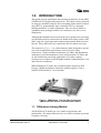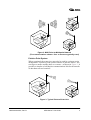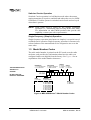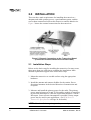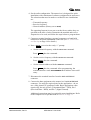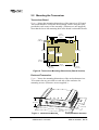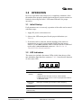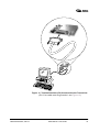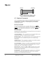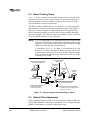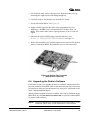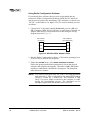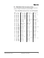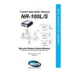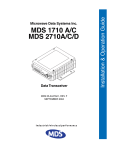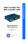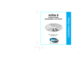
1
Board Version Enclosed Version 220 MHz and 450 MHz Data Transceivers MDS 05-3624A01, Rev. B JANUARY 2001 Installation and Operation Guide EL705 OEM Series™ QUICK START GUIDE Below are the basic steps for installing the transceiver. Detailed instructions are given in “Installation Steps” on page 6 of this guide. 1. Mount the transceiver (see Figure 6 or Figure 7 for mounting dimensions) 2. Install and connect the antenna system to the radio • Use only good quality, low loss coaxial cable. Keep the feedline as short as possible. • Preset directional antennas in the direction of desired transmission/reception. 3. Apply DC power to the radio (10–30 Vdc @ 500 mA minimum) • Measure the voltage source before connection. • Observe proper polarity. • Connect power to the power connector. 4. Set the radio’s basic configuration with a terminal (PC or HHT) connected to the INTERFACE port • Pin 23 of the INTERFACE port must be grounded to place the radio in the control and programming mode. (See Figure 12 on page 16 for a cable wiring diagram.) • Set the transmit frequency (TX xxx.xxx). • Set the receive frequency (RX xxx.xxx). • Set the network address (ADDR xxx). All radios in a given network must have the same address. • Set/verify the data rate using the BAUD command. The default setting is BAUD 9600 8N1. (Refer to “TRANSCEIVER PROGRAMMING” on page 14 for command details.) 5. Connect the data equipment to the radio’s INTERFACE connector • Connection to the radio must be made with a DB-25 Male connector. Connections for typical systems are shown below. • Connect only the required pins. Do not use a straight-through RS-232 cable with all pins wired. • Verify the data equipment is configured as DTE. (By default, the radio is configured as DCE.) 2 TXD RXD 3 3 RXD GND 7 7 GND DB-9 DB-25 RXD 2 3 RXD TXD 3 2 TXD GND 5 7 GND TRANSCEIVER (DCE) DB-25 2 RTU (DTE) DB-25 TXD DB-9 to DB-25 Example TRANSCEIVER (DCE) RTU (DTE) DB-25 to DB-25 Example NOTE: Additional connections may be needed in some installations. See Installation for details. 6. Verify proper operation by observing the LED display • See Table 5 on page 13 for a description of the status LEDs. • Refine directional antenna headings for maximum receive signal strength using the RSSI command. TABLE OF CONTENTS 1.0 INTRODUCTION ......................................................................... 1 1.1 Differences Among Models .............................................................. 1 Modem Speeds .................................................................................. 2 Frequency Coverage .......................................................................... 2 1.2 Applications ...................................................................................... 2 Point-to-Multipoint, Multiple Address Systems (MAS) ........................ 2 Point-to-Point System ......................................................................... 3 Switched Carrier Operation ................................................................ 4 Single Frequency (Simplex) Operation ............................................... 4 1.3 Model Number Codes ...................................................................... 4 1.4 Accessories ...................................................................................... 5 2.0 INSTALLATION ............................................................................ 6 2.1 Installation Steps .............................................................................. 6 2.2 Mounting the Transceiver ................................................................. 8 Transceiver Board............................................................................... 8 Enclosed Transceiver.......................................................................... 8 2.3 Antennas and Feedlines .................................................................. 9 Antennas ............................................................................................ 9 Feedlines ............................................................................................ 9 2.4 Power Connection .......................................................................... 10 Conservation (Sleep Mode).............................................................. 11 2.5 Data Interface Connections ............................................................ 11 3.0 OPERATION .............................................................................. 13 3.1 Initial Startup .................................................................................. 13 3.2 LED Indicators ................................................................................ 13 4.0 TRANSCEIVER PROGRAMMING ............................................ 14 4.1 Radio Programming Methods ........................................................ 14 PC with Radio Configuration Software .......................................... 14 À PC in Terminal Mode .................................................................... 14 Ã Handheld Terminal (HHT)............................................................. 14 4.2 PC Connection and Startup ........................................................... 14 4.3 Keyboard Commands ..................................................................... 16 Entering Commands......................................................................... 16 Error Messages ................................................................................ 16 4.4 Detailed Command Descriptions ................................................... 18 ADDR [NONE | 1–255] ..................................................................... 18 AMASK [0000 0000–FFFF FFFF] .................................................... 18 BAUD [xxxxx abc] ............................................................................. 19 CTS [0–255] ..................................................................................... 19 CTSHOLD [0–60000] ....................................................................... 19 MDS 05-3624A01, Rev. B OEM Series I/O Guide i DEVICE [DCE | CTS KEY] ............................................................... 20 DKEY................................................................................................ 20 INIT................................................................................................... 20 KEY .................................................................................................. 21 OWM [XXX...] ................................................................................... 21 OWN [XXX...].................................................................................... 21 PWR [L | M | H]................................................................................. 21 RSSI and RSSI!................................................................................ 22 RX [xxx.xxx]...................................................................................... 22 RXTOT [NONE | 1–255] ................................................................... 22 SER .................................................................................................. 22 SREV................................................................................................ 22 STAT ................................................................................................. 22 TOT [1–255 | ON | OFF] ................................................................... 23 TX [xxx.xxx] ...................................................................................... 23 5.0 TROUBLESHOOTING ............................................................... 24 5.1 LED Indicators ................................................................................ 24 5.2 Event Codes ................................................................................... 24 Checking for Alarms—STAT command............................................. 24 Major Alarms vs. Minor Alarms......................................................... 25 Event Code Definitions ..................................................................... 25 6.0 TECHNICAL REFERENCE ....................................................... 26 6.1 6.2 6.3 6.4 OEM Series™ Transceiver Specifications ...................................... 26 Bench Testing Setup ...................................................................... 28 Helical Filter Adjustment ................................................................ 28 Upgrading the Radio’s Software ..................................................... 29 Using Radio Configuration Software................................................. 30 6.5 dBm-Watts-Volts Conversion Chart ................................................ 31 7.0 GLOSSARY OF TERMS............................................................ 32 ii OEM Series I/O Guide MDS 05-3624A01, Rev. B Copyright Notice This Installation and Operation Guide and all software described herein are protected by copyright: 2001 Microwave Data Systems Inc. All rights reserved. Microwave Data Systems Inc. reserves its right to correct any errors and omissions in this publication. Antenna Installation Warning 1. All antenna installation and servicing is to be performed by qualified technical personnel only. When servicing the antenna, or working at distances closer than those listed below, ensure the transmitter has been disabled. RF Exposure 2. Typically, the antenna connected to the transmitter is a directional (high gain) antenna, fixed-mounted on the side or top of a building, or on a tower. Depending upon the application and the gain of the antenna, the total composite power could exceed 90 watts EIRP. The antenna location should be such that only qualified technical personnel can access it, and that under normal operating conditions no Separation distances other person can touch the antenna or approach within 2.3 meters of required for FCC RF Exposure compliance the antenna. Antenna Gain vs. Recommended Safety Distance (EL705 OEM Series) Antenna Gain (EL705 OEMSeries) Minimum RF Safety Distance 0–5 dBi 5–10 dBi 10–16.5 dBi 0.6 meter 1.06 meters 2.3 meters ISO 9001 Registration Microwave Data Systems adheres to this internationally accepted quality system standard. MDS 05-3624A01, Rev. B OEM Series I/O Guide iii MDS Quality Policy Statement We, the employees of Microwave Data Systems Inc., are committed to understanding and exceeding our customer’s needs and expectations. • We appreciate our customer’s patronage. They are our business. • We promise to serve them and anticipate their needs. • We are committed to providing solutions that are cost effective, innovative and reliable, with consistently high levels of quality. • We are committed to the continuous improvement of all of our systems and processes, to improve product quality and increase customer satisfaction. FM/UL/CSA Notice This product is available for use in Class I, Division 2, Groups A, B, C & D Hazardous Locations. Such locations are defined in Article 500 of the National Fire Protection Association (NFPA) publication NFPA 70, otherwise known as the National Electrical Code. The transceiver has been recognized for use in these hazardous locations by three independent agencies —Underwriters Laboratories (UL), Factory Mutual Research Corporation (FMRC) and the Canadian Standards Association (CSA). The UL certification for the transceiver is as a Recognized Component for use in these hazardous locations, in accordance with UL Standard 1604. The FMRC Approval is in accordance with FMRC Standard 3611. The CSA Certification is in accordance with CSA STD C22.2 No. 213-M1987. FM/UL/CSA Conditions of Approval: The transceiver is not acceptable as a stand-alone unit for use in the hazardous locations described above. It must either be mounted within another piece of equipment which is certified for hazardous locations, or installed within guidelines, or conditions of approval, as set forth by the approving agencies. These conditions of approval are as follows: 1. The transceiver must be mounted within a separate enclosure which is suitable for the intended application. 2. The antenna feedline, DC power cable and interface cable must be routed through conduit in accordance with the National Electrical Code. 3. Installation, operation and maintenance of the transceiver should be in accordance with the transceiver's installation manual, and the National Electrical Code. 4. Tampering or replacement with non-factory components may adversely affect the safe use of the transceiver in hazardous locations, and may void the approval. iv OEM Series I/O Guide MDS 05-3624A01, Rev. B 5. When installed in a Class I, Div. 2, Groups A, B, C or D hazardous location, observe the following: WARNING —EXPLOSION HAZARD— Do not disconnect equipment unless power has been switched off or the area is known to be non-hazardous. Refer to Articles 500 through 502 of the National Electrical Code (NFPA 70) for further information on hazardous locations and approved Division 2 wiring methods. ESD Notice (Board version only) To prevent malfunction or damage to this product, which may be caused by Electrostatic Discharge (ESD), the radio should be properly grounded at the time of installation. In addition, the installer or maintainer should follow proper ESD precautions, such as touching a bare metal object to dissapate body charge, prior to touching components or connecting/disconnecting cables. Cable Length Recomendation MDS recommends a maximum cable length of 3.0 meters for DC power and data connections to this product. Revision Notice While every reasonable effort has been made to ensure the accuracy of this manual, product improvements may result in minor differences between the manual and the product shipped to you. If you have additional questions or need an exact specification for a product, please contact our Customer Service Team using the information at the back of this guide. In addition, manual updates can often be found on the MDS Web site at www.microwavedata.com. Distress Beacon Warning In the U.S.A., the 406 to 406.1 MHz band is reserved for use by distress beacons. Since the MDS 4710A radio is capable of transmitting in this band, take precautions to prevent the radio from transmitting between 406 to 406.1 MHz. This notice applies only to MDS 4710A Transceivers used in the U.S.A. MDS 05-3624A01, Rev. B OEM Series I/O Guide v vi OEM Series I/O Guide MDS 05-3624A01, Rev. B 1.0 INTRODUCTION This guide presents installation and operating instructions for the MDS OEM Series™ of digital radio transceivers. The radios can be purchased as compact, modular boards for direct mounting inside remote terminal units (RTUs), programmable logic controllers (PLCs), automatic banking machines, or similar equipment. They are also available as standalone units packaged in their own enclosures (see lower cover illustration). Although this manual focuses on the board-level product, the operating specifications and user connections are identical for both versions of the radio. Only the visual appearance and mounting details differ between the two. These differences are explained in the text where necessary. The transceiver (Figure 1) is a data telemetry radio designed to operate in a point-to-multipoint environment, such as electric utility Supervisory Control and Data Acquisition (SCADA) and distribution automation, gas field automation, water and wastewater SCADA, and on-line transaction processing applications. The radio employs microprocessor control to provide highly reliable communications, even under adverse conditions. MDS OEM Series™ radios use continuous-phase frequency shift keying (CPFSK) modulation. Domestic models employ a 4-level modem; ETSI models, a 2-level modem. Invisible place holder Figure 1. OEM Series™ Series Data Transceiver (Board version shown—enclosed unit similar) 1.1 Differences Among Models All OEM Series™ models are very similar in appearance and functionality. The major differences are over-the-air modem speed and frequency coverage. MDS 05-3624A01, Rev. B OEM Series™ I/O Guide 1 Modem Speeds Domestic models are capable of 9600 bps transmission over the air; ETSI models, 4800 bps. This does not affect the local DATA INTERFACE port speed, which will accept asynchronous data between 1200 and 19200 bps. Frequency Coverage OEM Series radios are available for operation in the 200 MHz or 400 MHz frequency bands. The exact frequency coverage of each model is listed in the Specifications chart on Page 26. NOTE: The radio’s frequency range (band) cannot be set or changed by the user; it is set at the factory. 1.2 Applications Point-to-Multipoint, Multiple Address Systems (MAS) Point-to-multipoint (MAS) is the most common application of the transceiver. It consists of a central master station and several associated remote units as shown in Figure 2. An MAS network provides communications between a central host computer and remote terminal units (RTUs) or other data collection devices. The operation of the radio system is “transparent” to the computer equipment. That is, the radio system transports the data in its original form, making no changes to the data format. Often, the radio system is used to replace a network of remote monitors currently linked to a central location by leased telephone lines. At the central office of such a system, there is usually a large mainframe computer and some means of switching between individual lines coming from each remote monitor. In this type of system, there is a modulator/demodulator (modem) at the main computer and at each remote site, usually built into the remote monitor itself. Since the cost of leasing a dedicated-pair telephone line is quite high, radio is frequently used as an alternative communication medium. 2 OEM Series™ I/O Guide MDS 05-3624A01, Rev. B Invisible place holder io rad T R U TE O M RE io rad T R S E O T H PU M O C io rad T R R TEN ASTIO M A ST U TE O M RE Figure 2. MAS Point-to-Multipoint Network (Two remote stations shown—four or more are typically used) Point-to-Point System Where permitted, the transceiver may also be used in a point-to-point arrangement. A point-to-point system consists of just two radios—one serving as a master and the other as a remote—as shown in Figure 3. It provides a simplex or half-duplex communications link for the transfer of data between two locations. ra d io Invisible place holder T R S E O T H PU M ra d io O C U T R R TEN ASTIO M A ST TE O M RE Figure 3. Typical Point-to-Point Link MDS 05-3624A01, Rev. B OEM Series™ I/O Guide 3 Switched Carrier Operation Switched Carrier operation is a half-duplex mode where the master station transmitter is keyed to send data and unkeyed to receive. MDS OEM Series™ radios operate in switched carrier mode and are keyed when data is present. NOTE: MDS OEM Series™ radios do not support full-duplex operation (i.e., transmitting and receiving at the same time). For information on other MDS products that provide this capability, contact your sales representative. Single Frequency (Simplex) Operation Single frequency operation (also known as simplex) is a special case of switched carrier operation. Single frequency operation is automatically selected whenever the transmit and receive frequencies are set to the same value. 1.3 Model Number Codes The radio model number is printed on the PC board or on the radio enclosure, and provides key information about how the radio was configured when was shipped from the factory. See Figure 4 for an explanation of the model number characters. Invisible place holder THIS INFORMATION IS SUBJECT TO CHANGE. DO NOT USE FOR PRODUCT ORDERING. BANDWIDTH 1 = 12.5 kHz Domestic 2 = 12.5 kHz ETSI ENCLOSURE 0 = Without Enclosure 1 = With Enclosure EL705 BAND 2 = 200 MHz SUB-BAND A = 220240 MHz 4 = 400 MHz A = 330355 MHz B = 355380 MHz C = 380400 MHz D = 400420 MHz E = 420450 MHz F = 450470 MHz G = 480512 MHz H = 406430 MHz N AGENCY E = ETSI SAFETY F = FCC/IC N = None N = None C = CE Mark A N MODEM 2 = 4800 BPS 3 = 9600 BPS Figure 4. MDS OEM Series™ Model Number Codes 4 OEM Series™ I/O Guide MDS 05-3624A01, Rev. B 1.4 Accessories The transceiver can be used with one or more of the accessories listed in Table 1. Contact the factory for ordering information. Table 1. Optional Accessories MDS 05-3624A01, Rev. B Accessory Description MDS P/N Hand-Held Terminal Kit (HHT) Keypad terminal for programming, diagnostics, and control. Includes carrying case, cable set and an instruction booklet. (Accessory Power Adapter 03-3722A01 required for use with OEM radios—see below). 02-1501A01 Accessory Power Adapter DB-25 male-to-female adapter that attaches to the radio’s DATA INTERFACE connector. Provides regulated 10 Vdc for powering an HHT or other low power accessory. If not used, accessories could be damaged by excessive voltage (equal to the radio’s DC input voltage). 03-3722A01 RTU Simulator Assy. Test unit that simulates data from a remote terminal unit. Comes with polling software that runs on a PC. Used for testing OEM radio operation. (NOTE: Older MDS RTU Simulators will not work with the OEM radio as they require a higher input voltage.) 03-2094A01 DB-9 to DB-25 adapter Used to connect a PC with a 9-pin serial port to the radio’s DATA INTERFACE port. 01-3683A01 Radio Configuration Software (EL705) Radio programming software for use with a Windows-based PC. This program is available on 3.5” disks, and is included on the MDS’ InSite 6.4 (or higher) CD. 03-3649A01 PC Programming Adapter Kit Required when programming the radio with a personal computer operating in terminal mode. The adapter asserts the auto-open signal (ground) on pin 23 of the DATA INTERFACE port. A scratch-built cable may also be used for this purpose (see Figure 12 on Page 16). 01-3683A01 OEM Series™ I/O Guide 5 2.0 INSTALLATION There are three main requirements for installing the transceiver— adequate and stable primary power, a good antenna system, and the correct data connections between the transceiver and the data device. Figure 5 shows the external connections for the transceiver. Invisible place holder Figure 5. External Connections to the Transceiver Board (Connector locations identical to enclosed radio) 2.1 Installation Steps Below are the basic steps for installing the transceiver. In many cases, these steps alone are sufficient to complete the installation. More detailed explanations appear at the end of these steps. 1. Mount the transceiver to a stable surface using the appropriate hardware. 2. Install the antenna and antenna feedline for the station. Preset directional antennas in the desired direction of transmission and reception. 3. Measure and install the primary power for the radio. The primary power must be between 10 and 30 Vdc and be capable of supplying at least 600 milliamperes. (600 mA requirement assumes a 2 watt RF output. Lower current consumption is possible if lower output power may be used in your application—seeOEM Series™ Transceiver Specifications on Page 26 for details.) NOTE: Use the radio in negative ground systems only. 6 OEM Series™ I/O Guide MDS 05-3624A01, Rev. B 4. Set the radio configuration. The transceiver is designed for quick installation with a minimum of software configuration in most cases. The selections that must be made or verified for new installations are: • Transmit frequency • Receive frequency • Network address (factory-set to NONE) The operating frequencies are not set at the factory unless they are specified at the time of order. Determine the transmit and receive frequencies to be used, and follow the steps below to program them. 5. Connect a terminal interface (personal computer or a hand-held terminal) to the DATA INTERFACE connector. (See PC Connection and Startup on Page 14 for details.) 6. Press ENTER to receive the ready “>” prompt. a. Set the transmit frequency with the TX xxx.xxx command. Press ENTER after the command. b. Set the receive frequency with the RX xxx.xxx command. Press ENTER after the command. c. Set the network address with the ADDR xxx command. Press ENTER after the command. After programming, the terminal interface reads PROGRAMMED OK to indicate successful entry. 7. Disconnect the terminal interface from the DATA INTERFACE connector. 8. Connect the data equipment to the transceiver’s DATA INTERFACE connector. Use only the required pins for the application—do not use a fully pinned (25 conductor) cable. Basic applications often require only the use of Pin 2 (Transmitted Data—TXD), Pin 3 (Received Data—RXD), and Pin 7 (Signal Ground). Additional connections may be required in some installations. Refer to the complete list of pin functions in Table 4 on Page 11. MDS 05-3624A01, Rev. B OEM Series™ I/O Guide 7 2.2 Mounting the Transceiver Transceiver Board Figure 6 shows the mounting dimensions of the transceiver PC board. The board should be secured to the mounting surface using the holes provided at each corner of the assembly. (Fasteners are not supplied.) Note that the lower left mounting hole in the board is a threaded ferrule. Invisible place holder 4.53 in. (11.51 cm) DATA 0.23 in. (0.58 cm) PWR RF HEATSINK 3.23 in. (8.20 cm) 3.73 in. (9.47 cm) 1” in. (2.54 cm) 2.5 in. (6.35 cm) 0.28 in. (0.71 cm) HEATSINK HEIGHT: 0.38” (0.97 cm) 4.05 in. (10.29 cm) 0.28 in. (0.71 cm) 0.20 in. (0.51 cm) Figure 6. Transceiver Mounting Dimensions (Board Version) Enclosed Transceiver Figure 7 shows the mounting dimensions of the enclosed transceiver. Two cutout slots are provided on each side of the enclosure for mounting screws. (Fasteners are not supplied.) Invisible place holder 1.75 in. (4.45 cm) 3.25 in. (8.25 cm) 5.00 in. (12.70 cm) 5.97 in. (15.14 cm) 6.50 in. (16.51 cm) Figure 7. Transceiver Mounting Dimensions (Enclosed Version) 8 OEM Series™ I/O Guide MDS 05-3624A01, Rev. B 2.3 Antennas and Feedlines Antennas The transceiver can be used with a number of antennas. The exact style depends on the physical size and layout of the radio system. Suitable antennas are available from several manufacturers, including MDS. At master stations, omni-directional antennas (Figure 8) are typically used to provide equal coverage to all remote sites in the network. Invisible place holder Figure 8. Typical Omni-directional Antenna for Master Stations (Shown mounted to mast) At remote sites, a directional Yagi (Figure 9) or corner reflector antenna is generally recommended to minimize interference to and from other users. Invisible place holder Figure 9. Typical Yagi Antenna for Remote Sites Feedlines The selection of antenna feedline is very important. Poor quality cables should be avoided as they result in power losses that may reduce the range and reliability of the radio system. MDS 05-3624A01, Rev. B OEM Series™ I/O Guide 9 Tables 2 and 3 show the losses that occur when using various lengths and types of cable at 200 and 400 MHz, respectively. Regardless of the type of cable used, it should be kept as short as possible to minimize signal loss. Table 2. Length vs. Loss in Coaxial Cables at 200 MHz 3 Meters 15 Meters 30 Meters 150 Meters Cable Type (10 Feet) (46 Feet) (91 Feet) (525 Feet) RG-8A/U 0.32 dB 1.6 dB 3.2 dB 16 dB 1/2 inch HELIAX 0.10 dB 0.49 dB 0.98 dB 4.9 dB 7/8 inch HELIAX 0.05 dB 0.27 dB 0.54 dB 2.7 dB 1-1/4 inch HELIAX 0.04 dB 0.20 dB 0.40 dB 2.0 dB 1-5/8 inch HELIAX 0.03 dB 0.17 dB 0.33 dB 1.65 dB Table 3. Length vs. Loss in Coaxial Cables at 400 MHz 10 Feet 50 Feet 100 Feet 500 Feet (3.05 Meters) (15.24 Meters) (30.48 Meters) (152.4 Meters) RG-8A/U 0.51dB 2.53 dB 5.07 dB 25.35 dB 1/2 inch HELIAX 0.12 dB 0.76 dB 1.51 dB 7.55 dB 7/8 inch HELIAX 0.08 dB 0.42 dB 0.83 dB 4.15 dB 1-1/4 inch HELIAX 0.06 dB 0.31 dB 0.62 dB 3.10 dB 1-5/8 inch HELIAX 0.05 dB 0.26 dB 0.52 dB 2.60 dB Cable Type 2.4 Power Connection The transceiver can be operated from any well-filtered 10 to 30 Vdc power source. The power supply must be capable of providing at least 600 milliamperes if 2 watt output is planned. Supply the power to the power connector (see Figure 5 on Page 6). CAUTION POSSIBLE EQUIPMENT DAMAGE Do not power the radio through Pin 18 of the DB-25 Interface connector, as this does not provide over-current input protection for the radio. Pin 18 is intended only as an auxiliary output for powering a low-current (1.0 Amp max.) device, such as an RTU. NOTE: The radio is designed for use in negative ground systems only. 10 OEM Series™ I/O Guide MDS 05-3624A01, Rev. B Conservation (Sleep Mode) In some installations, such as at solar-powered sites, it may be necessary to keep the transceiver’s power consumption to an absolute minimum. This can be accomplished by configuring the data device (RTU, PLC, etc.) to ground Pin 12 of the DATA INTERFACE connector, which removes power from the radio. When the ground is removed, the radio is ready to operate within 75 milliseconds. 2.5 Data Interface Connections The transceiver’s DATA INTERFACE connector is configured as a DCE (modem) and is normally connected to an EIA-232 device. The transceiver supports over-the-air asynchronous data rates up to 19200 bps. Refer to Figure 10 and Table 4 for a detailed description of each pin on the DATA INTERFACE connector. CAUTION USE ONLY REQUIRED PINS Do not use a 25 wire (fully pinned) cable for connection to the DATA INTERFACE connector. Use only the required pins for the application. Damage may result if improper connections are made. For EIA-232 signaling, typical applications require the use of Pins 2, 3, and 7 only. Invisible place holder 13 25 1 14 Figure 10. Data Interface Connector Pinouts (As viewed from the front of the radio) Table 4. DATA INTERFACE Connector Pinouts Pin Number Input/ Output 1 -- Protective Ground. Connects to ground (negative supply potential) on the radio’s PC board and chassis. 2 IN TXD—Transmitted Data. Accepts TX data from the connected device. 3 OUT RXD—Received Data. Outputs received data to the connected device. 4 IN RTS—Request-to-Send Input. Causes CTS to go “high.” 5 OUT CTS—Clear-to-Send Output. Behavior depends on DEVICE command setting: Pin Description When DEVICE is set to DCE, this pin follows RTS and will provide “buffer full” flow control. When DEVICE is set to CTS KEY, this pin provides a keyline output when receive data is present. MDS 05-3624A01, Rev. B OEM Series™ I/O Guide 11 Table 4. DATA INTERFACE Connector Pinouts (Continued) 12 Pin Number Input/ Output Pin Description 6 OUT DSR—Data Set Ready. Active when radio is powered on. 7 -- Signal Ground. Connects to ground (negative supply potential) at radio’s PC board. 8 OUT DCD—Data Carrier Detect. Active when receiving data from another OEM Series radio with the same network address. 11 OUT Receive Audio Output. For test purposes only. 12 -- Sleep Mode. A logic low on this pin removes power from the radio. The radio is ready to operate 75 milliseconds after the ground is removed. 18 IN/OUT Accessory Power. Unregulated Output. Provides a source of output power for low current (1 Amp max.) accessories. Excessive drain on this connection causes the on board fuse (2 ampere) to open. The voltage at this pin matches the input voltage to the transceiver. Do not use this pin for powering the radio. 19 OUT 5.8 Vdc Regulated Output. Provides a source of regulated voltage at 100 mA for low power accessories. 23 IN Auto-Open. A logic low (less than 0.5 volts or ground) on this pin opens the diagnostic channel and disables normal data operation. A logic high (greater than 4 volts or open) enables the DATA INTERFACE for normal data operation. 25 OUT Alarm. A logic low (less than 0.5 volts) on this pin indicates normal operation. A logic high (greater than 4 volts) indicates that some alarm condition is present. This pin can be used as an alarm output, provided the internal series resistance of 1 kΩ is considered. OEM Series™ I/O Guide MDS 05-3624A01, Rev. B 3.0 OPERATION In-service operation of the transceiver is completely automatic. Once the unit has been properly installed and configured, operator actions are limited to observing the radio’s LED status indicators for proper operation. 3.1 Initial Startup If all parameters are set correctly, operation of the radio can be started with these steps: 1. Apply DC power to the transceiver. 2. Observe the LED status panel for the proper indications (see Table 5). 3. If not done earlier, refine the antenna heading of the station to maximize the received signal strength (RSSI) from the master station. Use the RSSI command from a terminal interface connected to the radio’s DATA INTERFACE connector.—See Section 4.0, TRANSCEIVER PROGRAMMING. 3.2 LED Indicators The transceiver includes four status LEDs visible from the top of the unit, behind the Data Interface connector. Table 5 describes the function of each status LED. PWR DCD TXD RXD Table 5. LED Status Indicators LED Name PWR (Power) Description • Continuous—Power is applied to the radio, no problems detected. • Rapid flash (five times-per-second)—Fault indication. • Flashing once every second—Unit is not programmed. Radio is in Bootloader mode. MDS 05-3624A01, Rev. B DCD (Data Carrier Detect) Flashing—Indicates another radio (with the same network address) is transmitting at the radio’s receive frequency. RXD (Receive Data) Receive data is present on DATA INTERFACE connector. TXD (Transmit Data) Transmit data is present on DATA INTERFACE connector. OEM Series™ I/O Guide 13 4.0 TRANSCEIVER PROGRAMMING Programming and set-up of the transceiver is performed through the radio’s DATA INTERFACE connector with a terminal interface—either a personal computer or a hand-held terminal (HHT). This section contains a reference chart of commands (Table 6) followed by detailed descriptions for each entry. 4.1 Radio Programming Methods ➊ PC with Radio Configuration Software PC-based Radio Configuration software is available for use with the radio (MDS P/N 03-3649A01). This software is normally supplied on 3.5” disks, but can also be found on the MDS InSite disk (version 6.4 or higher) under the title of “EL705.” On-line instructions are included with the configuration software. NOTE: When using radio configuration software, click on the opening screen or press a key to activate the program. ➋ PC in Terminal Mode A PC may also be used without the Radio Configuration software by operating it in a basic terminal mode (e.g., HyperTerminal session) and entering the radio commands listed in Table 6. The terminal communication parameters must be set to 9600 bps, with 8 data bits, no parity, and 1 stop bit (8N1). ➌ Handheld Terminal (HHT) A Hand-Held Terminal kit (MDS P/N 02-1501A01) may be used to enter the radio commands listed in Table 6. The HHT communication parameters must be set to 9600 bps, with 8 data bits, no parity, and 1 stop bit (8N1). 4.2 PC Connection and Startup Follow the steps below to prepare the radio for PC programming. For information about connecting and setting up a hand-held terminal, refer to the instructions provided with each HHT kit.: 1. Connect a PC to the radio’s DATA INTERFACE port as shown in Figure 11. Pin 23 of the interface cable must be grounded to activate the control and programming mode. This can be done with a Programming Adapter (MDS P/N 01-3683A01), or with a scratch-built cable as shown in Figure 12. 2. Press 14 ENTER to obtain the ready “>” prompt. OEM Series™ I/O Guide MDS 05-3624A01, Rev. B Invisible place holder Figure 11. Terminal Interface (PC) Connected to the Transceiver (Pin 23 on cable must be grounded—see Figure 12) MDS 05-3624A01, Rev. B OEM Series™ I/O Guide 15 Invisible place holder DB-25 MALE (TO RADIO) DB-9 FEMALE (TO COMPUTER) 2 TXD RXD 2 3 RXD TXD 3 7 GND GND 5 23 Diagnostics Open Figure 12. DB-25 to DB-9 Adapter Cable (For PC control and programming) 4.3 Keyboard Commands Table 6 is a reference chart of software commands for the transceiver. Programmable information is shown in brackets [ ] following the command name. See section 4.4 following the table for detailed command descriptions. Entering Commands To enter a command, type the command, followed by an ENTER keystroke. For programming commands, the command is followed by SPACE and the appropriate information or values, then ENTER . Error Messages Listed below are some possible error messages that may be encountered when using the terminal interface: UNKNOWN COMMAND—The command was not recognized. Refer to the command description for command usage information. INCORRECT ENTRY—The command format or its associated values were not valid. Refer to the command description for command usage information. COMMAND FAILED—The command was unable to successfully complete. This may indicate an internal software problem. NOT PROGRAMMED—Software was unable to program the internal radio memory or the requested item was not programmed.This is a serious internal radio error. Contact MDS for assistance. TEXT TOO LONG—Response to OWN or OWM command when too many characters have been entered. Refer to the command description for command usage information. NOT AVAILABLE—The entered command or parameter was valid, but it referred to a currently unavailable choice. Refer to the command description for command usage information. 16 OEM Series™ I/O Guide MDS 05-3624A01, Rev. B ACCESS DENIED—The command is unavailable to the user. Refer to the command descriptions for command information. EEPROM FAILURE— The INIT command was unable to write to EEPROM. This usually indicates a hardware error. Contact MDS for assistance. Table 6. Command summary Command name MDS 05-3624A01, Rev. B Function ADDR [NONE | 1–255] Details page 18 Set or display the network address of the radio. AMASK [0000 0000–FFFF FFFF] Details page 18 Set or display hex code identifying which events trigger an alarm. BAUD [xxxxx abc] Details page 19 Set or display the DATA INTERFACE data rate and format. CTS [0–255] Details page 19 Set or display the Clear-to-Send delay in milliseconds. CTSHOLD [0–60000] Details page 19 Set or display the delay, in milliseconds, at the end of a CTS line response; CTS Key operation only. DEVICE [DCE | CTS KEY] Details page 20 Set or display the CTS options. DKEY Details page 20 Dekey the radio (transmitter OFF) following a KEY command. INIT Details page 20 Set radio parameters to factory defaults. KEY Details page 21 Key the radio (transmitter ON). Provides a carrier for testing. OWM [XXX...] Details page 21 Set or display the owner’s message. OWN [XXX...] Details page 21 Set or display the owner’s name. PWR [L | M | H] Details page 21 Set or display the transmit power setting. RSSI and RSSI! Details page 22 Display the Received Signal Strength Indication. RX [xxx.xxx] Details page 22 Set or display the receive frequency. RXTOT [NONE | 1–255] Details page 22 Set or display the value of the receive time-out timer. SER Details page 22 Display the radio serial number. SREV Details page 22 Display the software revision level. OEM Series™ I/O Guide 17 Table 6. Command summary (Continued) Command name Function STAT Details page 22 Display the current alarm status. TOT [1–255 | ON | OFF] Details page 23 Set or display the time-out timer status and the timer delay in milliseconds. TX [xxx.xxx] Details page 23 Set or display the transmit frequency. 4.4 Detailed Command Descriptions The only essential commands for most applications are transmit frequency (TX xxx.xxx), receive frequency (RX xxx.xxx), and network address (ADDR xxx). However, proper use of the additional commands allows you to tailor the transceiver for a specific use or conduct basic diagnostics on the radio. This section gives more detailed information for the user commands previously listed in Table 6. In many cases, the commands shown here can be used in two ways. First, you can type only the command name to view the currently programmed data. Secondly, you can set or change the existing data by typing the command, followed by a space, and then the desired entry. In the list below, allowable data values, if any, are shown in brackets following the command name. The separator symbol (|) indicates that you can enter one of the values in the list. ADDR [NONE | 1–255] The ADDR command displays or sets the network address of the radio. In order for all the radios in a network to communicate, their network addresses must be identical, or set to NONE. (The radio is shipped from the factory with ADDR set to NONE.) AMASK [0000 0000–FFFF FFFF] The AMASK (alarm mask) command displays or sets which events cause the alarm output signal to be active. Normally, the mask is FFFF FFFF, meaning that any of the 32 possible events activate the alarm output signal. No special configuration is required for typical applications. Entering the AMASK command alone displays the current setting of alarm events in hexadecimal format. Entering the AMASK command followed by an eight-digit hexadecimal number reprograms the specified events to trigger an alarm. Each bit that is a ‘1’ identifies an associated alarm condition that can trigger the alarm output status line. Each bit that is a ‘0’ treats the associated alarm as irrelevant when deciding whether or not to assert the alarm output status line. 18 OEM Series™ I/O Guide MDS 05-3624A01, Rev. B Thus, an eight-digit hexadecimal number can classify up to 32 events as alarm triggers for the alarm output status line. See Table 7 on Page 25 for a list of the event codes and their hex values. The hex value of the mask is simply the sum of the hex values of the event codes corresponding to the alarm triggering events. BAUD [xxxxx abc] This command sets (or displays) the communication attributes for the DATA INTERFACE port. The first parameter (xxxxx) is baud rate. Baud rate is specified in bits-per-second (bps) and must be one of the following speeds: 1200, 2400, 4800, 9600, or 19200. The second parameter of the BAUD command (abc) is a three-character block indicating how the data is formatted: a = Data bits (7 or 8) b = Parity (N for None, c = Stop bits (1 or 2) O for Odd, E for Even) The factory default setting is 9600 baud, 8 data bits, no parity, 1 start bit, and 1 stop bit (Example: 9600 8N1). NOTE: 7N1, 8O2, and 8E2 are invalid communication settings and are not supported by the transceiver. CTS [0–255] The CTS (clear-to-send) command sets or displays the timer value associated with the CTS line response. The command parameter ranges from 0 to 255 milliseconds. For DCE operation (see DEVICE command), the timer specifies how long to wait after the RTS line goes high, before the radio asserts CTS. A CTS value of zero asserts the CTS line immediately after the RTS line goes high. For CTS Key operation (see DEVICE command), the timer specifies how long to wait after asserting the CTS, before data becomes available. A timer value of zero means that data is available as soon as received CTSHOLD [0–60000] For CTS Key operation (see DEVICE command), the CTSHOLD command sets or displays the timer value associated with the end of a CTS line response. The timer value specifies the length of time that CTS remains active following the last byte from the RXD pin of the DATA INTERFACE port. The time is in milliseconds. The default value is 0, which means that CTS drops immediately after the last byte. MDS 05-3624A01, Rev. B OEM Series™ I/O Guide 19 For DCE operation (see DEVICE command), this command has no effect. The response CTSHOLD n/a is displayed. DEVICE [DCE | CTS KEY] The DEVICE command sets or displays the device behavior of the radio. The command parameter is either DCE or CTS KEY. The default selection is DCE. In this mode, CTS goes high following RTS, subject to the CTS programmable delay time. Hardware flow control is implemented by signaling the CTS line if data arrives faster than it can be buffered and transmitted. The transceiver does not require an RTS/CTS handshake. Data is transmitted whenever there is data to send. If CTS KEY is selected, the CTS line transforms to a Receive Data indicator (with programmable delays) in order to provide a control line for use by other devices. The RTS line is ignored. CTS is asserted immediately following the receipt of RF data, but data is not sent out the DATA INTERFACE port until the CTS programmable delay time has expired. (See CTSHOLD description for the delay available following the data.) A typical use of CTSKEY is to provide a keyline (or RTS signal) for a half-duplex modem or other radio. DKEY This command deactivates the transmitter after it has been keyed with the KEY command. NOTE: The DKEY and KEY commands are not intended for normal operation. They are tools for field testing and installation. INIT The INIT command is used to re-initialize the radio’s operating parameters to the factory defaults. This may be helpful when trying to resolve configuration problems that may have resulted from the entry of one or more improper command settings. Entry of this command allows you to get back to a known working state. The following changes to the radio are made when INIT is entered: • • is set to FFFF FFFF BAUD is set to 9600 baud, 8 data bits, no parity, and 1 stop bit (9600 8N1) • CTS is set to 0 • CTSHOLD is set to 0 • DEVICE is set to DCE 20 AMASK OEM Series™ I/O Guide MDS 05-3624A01, Rev. B • • • is set to H [+33 dBm (2 watts)] RXTOT is set to NONE TOT is set to OFF PWR All other commands stay at their previously established settings. KEY This command activates the transmitter. The transmitter stays keyed until either the DKEY command is entered, or the transmitter time-out timer is enabled and times out. See also the DKEY and TOT commands. NOTE: The KEY and DKEY commands are not intended for normal operation. They are tools for field testing and installation. OWM [XXX...] This is a command to display or set an owner’s message. To program the owner’s message, type OWM then the message, followed by ENTER . The maximum number of characters that can be entered is 30. To display the owner’s message, type OWM then message appears on the display. ENTER . The owner’s OWN [XXX...] This is a command to display or set an owner’s name. To program the owner’s name, type OWN then the name, followed by ENTER . The maximum number of characters that can be entered is 30. To display the owner’s name, type OWN then name appears on the display. ENTER . The owner’s PWR [L | M | H] NOTE: This function may not be available, depending on certification requirements for a particular region. This command displays or sets the desired RF forward output power setting of the radio. The PWR command parameter is specified as L (low), M (medium), or H (high). The default setting is H. The values of L, M, and H are: L= M= H= MDS 05-3624A01, Rev. B 20 dBm (100 mW) 30 dBm (1 W) 33 dBm (2 W) OEM Series™ I/O Guide 21 RSSI and RSSI! These commands continuously display the radio’s Received Signal Strength Indication (RSSI) in dBm units. Incoming signal strengths from –50 dBm to –120 dBm are displayed. The RSSI command causes display of received signal strength, updated once every second. Press ENTER to terminate the display. The RSSI! command displays a one-time reading of the RSSI at the diagnostic port. RX [xxx.xxx] This command sets or displays the radio’s receive frequency in MHz. The frequency must be an integer multiple of the step size and must be in the valid range. If the entered frequency is invalid, the terminal interface displays the message INCORRECT ENTRY. NOTE: The frequency must be in the valid range for the sub-band purchased, and may not be programmed “between” channels. RXTOT [NONE | 1–255] The RXTOT command sets or displays the receive time-out timer value in minutes. This timer triggers an alarm (event 12) if data is not detected within the specified time. Entering the RXTOT command without a parameter displays the timer value in minutes. Entering the RXTOT command with a parameter ranging from 1 to 255 resets the timer in minutes. Entering the RXTOT command with the parameter NONE disables the timer. SER This command displays the radio’s serial number as recorded at the factory. SREV This command displays the software revision level of the transceiver firmware. STAT This command displays the current alarm status of the transceiver. If no alarms exist, the message NO ALARMS PRESENT appears at the top of the terminal display. 22 OEM Series™ I/O Guide MDS 05-3624A01, Rev. B If an alarm does exist, a two-digit code (00–31) is displayed and the alarm is identified as MAJOR or MINOR. A brief description of the alarm code is also given. Detailed descriptions of event codes are provided in Table 7 on Page 25. If more than one alarm exists, the word MORE appears at the bottom of the screen and additional alarms are viewed by pressing the ENTER key. Alarms are displayed in ascending order, major alarms before minor ones. TOT [1–255 | ON | OFF] This command sets or displays the transmitter time-out timer value (1–255 seconds), as well as the timer status (ON or OFF). The command parameter can be either the timer value or the status, but not both. The parameter ON enables the timer; OFF disables the timer. If the timer is on, and the radio remains keyed for a longer duration than the TOT value, the transmitter is automatically unkeyed. When this happens, the radio must be commanded back to an unkeyed state before a new keying command is accepted. By default the timer is ON and set to 30 seconds. TX [xxx.xxx] This command sets or displays the radio’s transmit frequency in MHz. The frequency must be an integer multiple of the step size and must be in the valid range. If the entered frequency is invalid, the terminal interface displays the message INCORRECT ENTRY. NOTE: The frequency must be in the valid range for the sub-band purchased, and may not be programmed “between” channels. MDS 05-3624A01, Rev. B OEM Series™ I/O Guide 23 5.0 TROUBLESHOOTING Successful troubleshooting of the radio system is not difficult, but it requires a logical approach. It is best to begin troubleshooting at the master station, as the rest of the system depends on the master for polling commands. If the master station has problems, the operation of the entire network can be compromised. It is good practice to start by checking the simple things. For proper operation, all radios in the network must meet these basic requirements: • Adequate and stable primary power. • Secure connections (RF, data, and power). • An efficient and properly aligned antenna system with a good received signal strength (at least –90 dBm). It is possible for a system to operate with weaker signals, but reliability may be degraded. • Proper programming of the transceiver’s operating parameters (see Section 4.0, TRANSCEIVER PROGRAMMING). • The correct interface between the transceiver and the connected data equipment (correct cable wiring, proper data format, timing, etc.). 5.1 LED Indicators The LED status indicators are an important troubleshooting tool and should be checked whenever a problem is suspected. Table 5 on Page 13 describes the function of each status LED. 5.2 Event Codes When an alarm condition exists, the transceiver creates a code that can be read on a terminal connected to the DATA INTERFACE port. These codes can be very helpful in resolving many system difficulties. Table 7 lists the definitions of the event codes. Checking for Alarms—STAT command To check for alarms, enter STAT on the terminal interface. If no alarms exist, the message NO ALARMS PRESENT appears at the top of the display. If an alarm does exist, the STAT command displays a two-digit alarm code (00–31) and the event is identified as a Major or Minor Alarm. A brief description of the alarm is also given. If more than one alarm exists, the word MORE appears at the bottom of the screen. To view additional alarms, press ENTER . 24 OEM Series™ I/O Guide MDS 05-3624A01, Rev. B Major Alarms vs. Minor Alarms Major Alarms—report serious conditions that generally indicate a hardware failure, or other abnormal conditions that prevent (or seriously degrade) further operation of the transceiver. Major alarms generally indicate the need for factory repair. Contact MDS for further assistance. Minor Alarms—report conditions that, under most circumstances do not prevent transceiver operation. These include out-of-tolerance conditions, baud rate mismatches, etc. The cause of these alarms should be investigated and corrected to prevent possible system failure. Event Code Definitions Table 7 contains a listing of the event codes that may be reported by the transceiver. Table 7. Event Codes Event Code Hex Value Event Class Description STATUS Message 00 0000 0000 -- No alarms present. No Alarms Present 1–3 -- -- Not used. -- 04 0800 0000 Major One or both of the internal programmable synthesizer loops is reporting an out-of-lock condition. Synthesizer Out-of-Lock 5–7 -- -- Not used. -- 08 0080 0000 Major The system is reporting that it has not been calibrated. Factory calibration is required for proper radio operation. Radio Not Calibrated 09 -- -- Not used. -- 10 0020 0000 Major The internal microcontroller was unable to properly program the system to the appropriate EEPROM defaults. A hardware problem may exist. EEPROM Write Failure 11 -- -- Not used. -- 12 0008 0000 Major Receiver time-out. No data received within the specified receiver time-out time. Receiver time-out 13 0004 0000 Major Transmitter time-out. The radio was keyed for a duration exceeding the time-out timer setting. (This alarm clears the next time the radio keys.) Transmitter time-out 14–16 -- -- Not used. -- 17 0000 4000 Minor A data parity fault has been detected on the DATA INTERFACE connector. This usually indicates a parity setting mismatch between the radio and the RTU. Data Parity Error 18 0000 2000 Minor A data framing error has been detected on the DATA INTERFACE connector. This may indicate a baud rate mismatch between the radio and the RTU. Data Framing Error 19–30 -- -- Not used. -- MDS 05-3624A01, Rev. B OEM Series™ I/O Guide 25 6.0 TECHNICAL REFERENCE 6.1 OEM Series™ Transceiver Specifications MODELS MDS OEM Series™ 200: Licensed 200 MHz Transceiver MDS OEM Series™ 400: Licensed 400 MHz Transceiver RADIO TYPE Synthesized, half duplex, 12.5 kHz channel spacing, split frequency, or simplex ENVIRONMENTAL Temperature Range: –30 to +60 degrees C Humidity: 0 to 95% at 40 degrees C Board Dimensions: 4.53″ W x 0.75″ H x 3.73″ D 11.51 cm W x 1.90 cm H x 9.47 cm D Enclosed Dimensions: 6.5″ W x 1.75″ H x 5.00″ D 16.51 cm W x 4.45 cm H x 12.70 cm D Weight: (Board version) 4.5 oz. (0.13 kg) (Enclosed version) 1 lb. (0.45 kg) RF Connector: BNC Enclosure Type (if furnished): Aluminum TRANSMITTER 26 Frequency Ranges (200 MHz): 220 to 240 MHz Frequency Ranges (400 MHz): 330 to 355 MHz 355 to 380 MHz 380 to 400 MHz 400 to 420 MHz 420 to 450 MHz 450 to 480 MHz 480 to 512 MHz 406 to 430 MHz (Canadian Plan) Frequency Increments: 6.25 kHz (Standard) 5 kHz (Special) Modulation Type: 4 level CPFSK Carrier Power: 100 mW, 1 W, 2 W programmable (+20 DBM, +30 dBM, +33 dBM) Duty Cycle: 50% (100% with additional heatsinking) Output Impedance: 50 ohms Frequency Stability: 1.5 ppm, –30 to +60 degrees C Channel Spacing: 12.5 kHz Spurious and Harmonics: –65 dBc Time-out Timer: 1 to 255 seconds Transmitter Keying: On data Key-up Time: 2 ms OEM Series™ I/O Guide MDS 05-3624A01, Rev. B RECEIVER Type: Double conversion superheterodyne (84 MHz and 450 MHz IF) Frequency Ranges (200 MHz): 220 to 240 MHz Frequency Ranges (400 MHz): 330 to 355 MHz 355 to 380 MHz 380 to 400 MHz 400 to 420 MHz 420 to 450 MHz 450 to 480 MHz 480 to 512 MHz 406 to 430 MHz (Canadian Plan) Frequency Increments: 6.25 kHz (Standard) 5 kHz (Special) Frequency Stability: 1.5 ppm, –30 to +60 degrees C Spurious and Image Rejection: –70 dB Sensitivity: 12 dB Sinad @ –116 dBm Data Performance: 1 x 10⁻⁶ @ –108 dBm Intermodulation Rejection: –70 dB minimum Selectivity: 60 dB typical at adjacent channel (EIA) Bandwidth: 12.5 kHz DATA INTERFACE RS-232 through DB-25 Connector Baud Rates at Interface Port: 1200, 2400, 4800, 9600, and 19200* bps Over-the-Air Data Rate: 9600 bps 4800 bps (ETSI) Data Latency: < 20 ms typical DIAGNOSTICS Self Test: Yes Local RS-232 RSSI and Setup: Yes 4 LED Display: PWR, DCD, TXD, and RXD PRIMARY POWER Voltage: 10 to 30 Vdc through a 5.5 mm pin plug or 2-pin MDS connector RX Current at 13.8 Vdc (typical): 75 mA TX Current at 13.8 Vdc (typical): 575 mA @ high power (2W) 435 mA @ medium power (1W) 260 mA @ low power (100 mW) TX Current at 24 Vdc (typical): 325 mA @ high power (2W) 250 mA @ medium power (1W) 150 mA @ low power (100 mW) :Circuit Protection: 2 amp fuse, surface mount Reverse Polarity Protection: Diode across primary input * At 19200 bps, the radio operates in a buffered mode, storing 50 characters at a time. MDS 05-3624A01, Rev. B OEM Series™ I/O Guide 27 6.2 Bench Testing Setup Figure 13 shows a sample test setup that can be used to verify the basic operation of transceivers in a shop setting. The test can be performed with any number of remote radios by using a power divider with the required number of output connections. The RTU simulator (MDS Part No. 03-2094A01) is a microcontroller that emulates a remote terminal unit operating at 1200, 2400, 4800, or 9600 bps. Custom software is supplied with the RTU simulator that allows continuous polling of remote radios using an IBM-compatible personal computer. The software reports the number of polls sent, polls received, and the number of errors detected. NOTE: It is very important to use attenuation between all units in the test setup. The amount of attenuation required depends on the number of units being tested and the desired signal strength (RSSI) at each transceiver during the test. A maximum level of -50 dBm is recommended at each transceiver, because the radio’s RSSI reporting will not be accurate above this level. In no case should a signal stronger than +10 dBm be applied to any transceiver in the test setup, or damage may result. Invisible place holder RTU SIMULATORS (SEE TEXT) COMPUTER RUNNING MDS POLL.EXE PROGRAM REMOTE RADIO REMOTE RADIO REMOTE RADIO REMOTE RADIO MASTER STATION POWER DIVIDER POWER ATTENUATORS • Fixed or adjustable • 2W minimum rating NON-RADIATING ATTENUATOR • Install on any unused divider ports • 2W minimum rating Figure 13. Typical setup for bench testing of radios 6.3 Helical Filter Adjustment If the operating frequency of the radio is changed more than 5 MHz, the helical filters should be adjusted for maximum received signal strength (RSSI). If adjustment is required, follow these steps: 28 OEM Series™ I/O Guide MDS 05-3624A01, Rev. B 1. For enclosed units, remove the top cover from the transceiver by loosening the eight screws and lifting straight up. 2. Carefully remove the shield cover from the PC board. 3. Locate the helical filters. See Figure 14. 4. Apply a steady signal to the radio at the programmed receive frequency (–80 dBm level recommended; no stronger than –60 dBm). This can be done with a signal generator or an over-the-air signal. 5. Measure the radio’s RSSI using a terminal interface. See Section 4.0, TRANSCEIVER PROGRAMMING on Page 14. 6. With a non-metallic tool, carefully adjust each section of the helical filter for maximum RSSI. Re-install the cover to the transceiver. Invisible place holder HELICAL ADJUSTMENTS HELICAL ADJUSTMENTS Figure 14. Helical Filter Location (Shield cover removed) 6.4 Upgrading the Radio’s Software From time to time, new product features or software maintenance files become available from MDS. This section describes the steps necessary to install new software into the transceiver using a PC connected to the radio’s DATA INTERFACE port. When software upgrades become available, they can be obtained on the MDS Web site at www.microwavedata.com, or you can contact MDS to request radio software. NOTE: Software upgrades are distributed as ASCII files with a “.S28” extension. These files use the Motorola S-record format. MDS 05-3624A01, Rev. B OEM Series™ I/O Guide 29 Using Radio Configuration Software If you already have software that you wish to download into the transceiver, Radio Configuration Software (MDS P/N 03-3649A01) may be used to perform the installation. (This software is referred to as “EL705” on the InSite 6.4 or higher CD.) To use this method, proceed as follows: 1. Connect a PC to the radio’s DATA INTERFACE port via a DB-9 to DB-25 adapter (MDS P/N 01-3683A01 or equivalent). If desired, an adapter cable may be constructed from scratch using the wiring diagram shown in Figure 15. Invisible place holder DB-25 MALE (TO RADIO) DB-9 FEMALE (TO COMPUTER) 2 TXD RXD 2 3 RXD TXD 3 7 GND GND 5 Figure 15. DB-25 to DB-9 Adapter Cable 2. Run the Radio Configuration software. (Click on the opening screen or press a key to activate the program.) 3. Under the SYSTEM menu, select RADIO SOFTWARE UPGRADE. Follow the prompts and online instructions to locate the desired software and complete the upgrade. The radio’s PWR LED flashes rapidly to confirm that a download is in progress. The download takes about two minutes. NOTE: If a software download fails, the radio is left unprogrammed and inoperative. This is indicated by the PWR LED flashing slowly (1 second on, 1 second off). This condition is only likely if a power failure occurred to the computer or radio during the downloading process. The download can be attempted again when the fault has been corrected. 30 OEM Series™ I/O Guide MDS 05-3624A01, Rev. B 6.5 dBm-Watts-Volts Conversion Chart Table 8 is provided as a convenience for determining the equivalent wattage or voltage of an RF power expressed in dBm. Table 8. dBm-Watts-Volts Conversion—for 50 Ohm Systems MDS 05-3624A01, Rev. B dBm V Po dBm V Po dBm mV +53 +50 +49 +48 +47 +46 +45 +44 +43 +42 +41 +40 +39 +38 +37 +36 +35 +34 +33 +32 +31 +30 +29 +28 +27 +26 +25 +24 +23 +22 +21 +20 +19 +18 +17 +16 +15 +14 +13 +12 +11 +10 +9 +8 +7 +6 +5 +4 +3 +2 +1 200W 100W 80W 64W 50W 40W 32W 25W 20W 16W 12.5W 10W 8W 6.4W 5W 4W 3.2W 2.5W 2W 1.6W 1.25W 1.0W 800mW 640mW 500mW 400mW 320mW 250mW 200mW 160mW 125mW 100mW 80mW 64mW 50mW 40mW 32mW 25mW 20mW 16mW 12.5mW 10mW 8mW 6.4mW 5mW 4mW 3.2mW 2.5mW 2.0mW 1.6mW 1.25mW 0 -1 -2 -3 -4 -5 -6 -7 -8 -9 -10 -11 -12 -13 -14 -15 -16 1.0mW .80mW .64mW .50mW .40mW .32mW .25mW .20mW .16mW .125mW .10mW -49 -50 -51 -52 -53 -54 -55 -56 -57 -58 -59 -60 -61 -62 -63 -64 100.0 70.7 64.0 58.0 50.0 44.5 40.0 32.5 32.0 28.0 26.2 22.5 20.0 18.0 16.0 14.1 12.5 11.5 10.0 9.0 8.0 7.10 6.40 5.80 5.00 4.45 4.00 3.55 3.20 2.80 2.52 2.25 2.00 1.80 1.60 1.41 1.25 1.15 1.00 .90 .80 .71 .64 .58 .500 .445 .400 .355 .320 .280 .252 .225 .200 .180 .160 .141 .125 .115 .100 .090 .080 .071 .064 .058 .050 .045 .040 .0355 dBm µV dBm mV -17 -18 -19 -20 -21 -22 -23 -24 -25 -26 -27 -28 -29 -30 -31 -32 -33 -34 -35 -36 -37 -38 -39 -40 -41 -42 -43 -44 -45 -46 -47 -48 31.5 28.5 25.1 22.5 20.0 17.9 15.9 14.1 12.8 11.5 10.0 8.9 8.0 7.1 6.25 5.8 5.0 4.5 4.0 3.5 3.2 2.85 2.5 2.25 2.0 1.8 1.6 1.4 1.25 1.18 1.00 0.90 Po .01mW .001mW .1µW -65 -66 -67 -68 -69 -70 -71 -72 -73 -74 -75 -76 -77 -78 -79 -80 -81 -82 -83 -84 -85 -86 -87 -88 -89 -90 -91 -92 -93 -94 -95 -96 -97 Po 0.80 0.71 .01µW 0.64 0.57 0.50 0.45 0.40 0.351 0.32 0.286 0.251 0.225 .001µW 0.200 0.180 0.160 0.141 128 115 100 90 80 71 65 58 50 45 40 35 32 29 25 22.5 20.0 18.0 16.0 11.1 12.9 11.5 10.0 9.0 8.0 7.1 6.1 5.75 5.0 4.5 4.0 3.51 3.2 OEM Series™ I/O Guide Po .1nW .01nW .001nW dBm µV -98 -99 -100 -101 -102 -103 -104 -105 -106 2.9 2.51 2.25 2.0 1.8 1.6 1.41 1.27 1.18 dBm nV -107 -108 -109 -110 -111 -112 -113 -114 -115 -116 -117 -118 -119 -120 -121 -122 -123 -124 -125 -126 -127 -128 -129 -130 -131 -132 -133 -134 -135 -136 -137 -138 -139 -140 1000 900 800 710 640 580 500 450 400 355 325 285 251 225 200 180 160 141 128 117 100 90 80 71 61 58 50 45 40 35 33 29 25 23 Po .1pW Po .01pW .001pW .1ƒW .01ƒW 31 7.0 GLOSSARY OF TERMS If you are new to digital radio systems, some of the terms used in this guide may be unfamiliar. The following glossary explains many of these terms and is helpful in understanding the operation of the transceiver. Antenna System Gain—A figure, normally expressed in dB, representing the power increase resulting from the use of a gain-type antenna. System losses (from the feedline and coaxial connectors, for example) are subtracted from this figure to calculate the total antenna system gain. Bit—The smallest unit of digital data, often represented by a one or a zero. Eight bits (plus start, stop, and parity bits) usually comprise a byte. Bits-per-second—See BPS. BPS—Bits-per-second. A measure of the information transfer rate of digital data across a communication channel. Byte—A string of digital data usually made up of eight data bits and start, stop and parity bits. Data Circuit-terminating Equipment—See DCE. Data Communications Equipment—See DCE. Data Terminal Equipment—See DTE. dBi—Decibels referenced to an “ideal” isotropic radiator in free space. Frequently used to express antenna gain. dBm—Decibels referenced to one milliwatt. An absolute unit used to measure signal power, as in transmitter power output, or received signal strength. DCE—Data Circuit-terminating Equipment (or Data Communications Equipment). In data communications terminology, this is the “modem” side of a computer-to-modem connection. The MDS OEM Series™ is a DCE device. Decibel (dB)—A measure computed from the ratio between two signal levels. Frequently used to express the gain (or loss) of a system. DTE—Data Terminal Equipment. A device that provides data in the form of digital signals at its output. Connects to the DCE device. ETSI—European Telecommunications Standards Institute. A non-profit group that produces and approves standards for use throughout Europe and other locations pertaining to communications equipment and systems. 32 OEM Series™ I/O Guide MDS 05-3624A01, Rev. B Fade Margin—The greatest tolerable reduction in average received signal strength that is anticipated under most conditions. Provides an allowance for reduced signal strength due to multipath, slight antenna movement, or changing atmospheric losses. A fade margin of 20 is usually sufficient in most systems. Hardware Flow Control—A transceiver feature used to prevent data buffer overruns when handling high-speed data from the RTU or PLC. When the buffer approaches overflow, the radio drops the clear-to-send (CTS) line, which instructs the RTU or PLC to delay further transmission until CTS again returns to the high state. Host Computer—The computer installed at the master station site, which controls the collection of data from one or more remote sites. Latency—The delay (usually expressed in milliseconds) between when data is applied to TXD (Pin 2) at one radio, until it appears at RXD (Pin 3) at the other radio. MAS—Multiple Address System. A radio system where a central master station communicates with several remote stations for the purpose of gathering telemetry data. Master (Station)—Radio which is connected to the host computer. It is the point at which polling enters the network. Multiple Address System—See MAS. PLC—Programmable Logic Controller. A dedicated microprocessor configured for a specific application with discrete inputs and outputs. It can serve as a host or as an RTU. Point-to-Multipoint System—A radio communications network or system designed with a central control station that exchanges data with a number of remote locations equipped with terminal equipment. Poll—A request for data issued from the host computer (or master PLC) to a remote radio. Programmable Logic Controller—See PLC. Received Signal Strength Indication—See RSSI. Redundant Operation—A station arrangement where two transceivers and two power supplies are available for operation, with automatic switchover in case of a failure. Remote (Station)—A radio in a network that communicates with an associated master station. Remote Terminal Unit—See RTU. MDS 05-3624A01, Rev. B OEM Series™ I/O Guide 33 RSSI—Received Signal Strength Indication. A measure, in dBm, of the strength of the signal received by a radio from an antenna. The radio must be properly calibrated for the RSSI value to be meaningful. RTU—Remote Terminal Unit. A data collection device installed at a remote radio site. SCADA—Supervisory Control And Data Acquisition. An overall term for the functions commonly provided through an MAS radio system. Supervisory Control And Data Acquisition—See SCADA. 34 OEM Series™ I/O Guide MDS 05-3624A01, Rev. B INDEX A SER (display radio serial number 22 SREV (display software revision level) 22 STAT (display current alarm status) 22 terminal interface 16 TOT (set/display time-out value and timer status) 23 TX (set/display transmit frequency) 23 Connections to radio, illustrated 6 Conversions, dBm-Watts-Volts 31 CTS command 19 CTS pinout (Pin 5) 11 ACCESS DENIED error message 17 Accessories 5 Accessory power adapter 5 Accessory Power pinout (Pin 18) 12 Adapters accessory power adapter 5 DB-9 to DB-25 5 PC programming adapter kit 5 Alarms alarm code definitions 25 major vs. minor 25 pinout (Pin 25) 12 using STAT command to display 22 AMASK command 18 Antenna installation 6 RSSI command used to refine heading 13 system gain, defined 32 Yagi, illustrated 9 Applications 2 Multiple Address Systems (MAS) 2 point-to-multipoint system 2 point-to-point system 3 Auto-Open, pinout (Pin 23) 12 D B BAUD command 19 Bench testing (radio performance) 28 Bit, defined 32 Bits-per-second. See BPS BPS (bits-per-second), defined 32 Byte, defined 32 C Cable, loss due to length of coaxial 10 COMMAND FAILED error message 16 Command summary, table 17 Commands AMASK (set/display alarm triggers) 18 BAUD (set/display rate, encoding) 19 CTS (set/display CTS line response timer) 19 descriptions 18 DEVICE (set/display radio behavior) 20 DKEY (deactivate transmitter after KEY command) 20 entering on terminal interface 16 INIT (reinitialize radio to factory defaults) 20 KEY (activate transmitter) 21 OWM (set/display owner’s message) 21 OWN (set/display owner’s name) 21 PWR (set/display RF forward output power) 21 RSSI (display RSSI) 22 RX (set/display receive frequency) 22 RXTOT (set/display receive time-out timer value) 22 MDS 05-3624A01, Rev. B Data interface connector pinouts 11 installing connection 11 specifications 27 dB. See Decibel 32 DB-9 to DB-25 adapter 5 illustrated 16, 30 dBi, defined 32 dBm, defined 32 DCD pinout (Pin 8) 12 DCD LED description 13 DCE (Data Cirtuit-terminating Equipment), defined 32 Decibel (dB), defined 32 Description, product 1 DEVICE command 20 Diagnostic Channel Enable, pinout (Pin 23) 12 Diagnostics interface specifications 27 Differences among models 1 Display alarm status (STAT command) 22 alarm triggers (AMASK command) 18 baud rate and encoding (BAUD command) 19 CTS line response timer (CTS command) 19 owner’s message (OWM command) 21 owner’s name (OWN command) 21 radio behavior (DEVICE command) 20 radio serial number (SER command) 22 receive frequency (RX command) 22 receive time-out timer value (RXTOT command) 22 RF forward output power (PWR command) 21 RSSI (RSSI command) 22 software revision level (SREV command) 22 time-out value and timer status (TOT command) 23 transmit frequency (TX command) 23 DKEY command 20 Downloading new software 29 DSR pinout (Pin 6) 12 DTE (Data Terminal Equipment), defined 32 OEM Series™ I/O Guide I-1 E EEPROM FAILURE error message 17 Enable/disable diagnostic channel, pinout (Pin 23) 12 Environment specifications 26 Error messages 16 access denied 17 command failed 16 EEPROM failure 17 incorrect entry 16 not available 16 not programmed 16 text too long 16 unknown command 16 F Fade margin, defined 33 Feedlines 9 Filter, helical, adjustment 28 Frequency adjusting helical filter when changed 28 setting. See TX and RX commands G Glossary 32 Ground protective (Pin 1) 11 signal (Pin 7) 12 H Half-duplex 3 switched carrier operation 4 Hand-Held Terminal (HHT) 5 Hardware flow control, defined 33 Helical filter adjusting 28 locations, illustrated 29 Host computer, defined 33 I Illustrations antenna, Yagi 9 board version 1 connections to radio 6 DB-25 to DB-9 adapter cable 16, 30 helical filter locations 29 MDS OEM Series™ model number codes 4 point-to-point link 3 terminal interface connected to transceiver 15 transceiver mounting dimensions, enclosed version 8 INCORRECT ENTRY error message 16 INIT command 20 Installation 6–12 antenna 6 configuring transceiver 7 DATA INTERFACE connection 7 data interface connections 11 power 6 power connection 10 MDS 05-3624A01, Rev. B steps 6 K KEY command 21 Keying on data (DKEY command) 20 switched carrier operation 4 switched carrier, defined 4 L Latency, defined 33 LEDs DCD 13 indicators, described 13 PWR 13 RXD 13 RXD, Pin 3 11 status indicators, illustrated 13 TXD 13 TXD, Pin 2 11 Loss. See Signal M MAS (Multiple Address System) 2 defined 33 Master Station defined 33 keying behavior 4 Model number codes 4 MDS OEM Series™, illustrated 4 Models system specifications 26 N NOT AVAILABLE error message 16 NOT PROGRAMMED error message 16 O Operation 13 environment, specifications for 26 Output, 5.8 Vdc regulated, pinout (Pin 19) 12 OWM command 21 OWN command 21 Owner’s message, set/display. See OWM command Owner’s name, set/display. See OWN command P PC Programming Adapter Kit 5 Performance testing 28 Pinouts on data interface 11 PLC (Programmable Logic Controller), defined 33 Point-to-multipoint defined 33 system 2 Point-to-point link, illustrated 3 system 3 OEM Series™ I/O Guide I-2 Poll, defined 33 Power connection 10 installing 6 LED status indicator (PWR LED) 13 RF, chart for converting dBm-Watts-Volts 31 Power attenuators, use of in testing 28 Power conservation 10 Primary power specifications 27 Procedures checking for alarms (STAT command) 24 connecting terminal interface 14 downloading new software 29 entering commands using a terminal interface 16 helical filter adjustment 28 installation 6 operation 13 performance optimization 13 reading LED status indicators 13 troubleshooting 24 Product accessories 5 description 1 display radio serial number (SER command) 22 model number codes 4 Programming, transceiver 14–17 PWR command 21 PWR LED description 13 R Radio configuration software 5, 29 serial number, displaying (SER command) 22 Radio type system specifications 26 Receive Audio Output pinout (Pin 11) 12 Received signal strength indication See RSSI 34 Receiver specifications 27 Redundant operation, defined 33 Remote Station, defined 33 Resetting transceiver (INIT command) 20 Revision level display software (SREV command) 22 RSSI adjusting helical filter for increased signal strength 28 command 22 command, used to refine antenna heading 13 defined 34 RTS pinout (Pin 4) 11 RTU (Remote Terminal Unit) defined 34 RTU simulator 5, 28 RX command 22 RXD LED description 13 Pin 3 11 RXTOT command 22 MDS 05-3624A01, Rev. B S SCADA (Supervisory Control And Data Acquisition), defined 34 SER command 22 Set alarm triggers (AMASK command) 18 receive time-out timer value (RXTOT command) 22 Signal ground (Pin 7) 12 loss due to coaxial cable length, table 10 Simplex 3 single-frequency operation 4 special case of switched carrier operation 4 Software control from PC 29 display revision level 22 upgrades (.S28 files) 29 upgrading 29 Specifications data interface 27 diagnostics interface 27 environment 26 models 26 primary power 27 radio type 26 receiver 27 transceiver 26–27 transmitter 26 SREV command 22 STAT command 22 Switched carrier operation 4 T Tables accessories 5 alarm code definitions 25 command summary 17 conversions, dBm-Watts-Volts 31 data interface connector pinouts 11 LED status indicators 13 length vs. loss in coaxial cables 10 Technical reference 26–31 bench test setup 28 Terminal Interface connected to transceiver, illustrated 15 connection and startup 14 entering commands 16 error messages displayed on 16 keyboard commands 16 Testing. See bench testing TEXT TOO LONG error message 16 Timer, set/display time-out value and status (TOT command) 23 TOT command 23 Transceiver applications 2 board version, illustrated 1 configuring for operation 7 dimensions, mounting enclosed version, illustrated 8 mounting 6 mounting board version 8 mounting enclosed version 8 programming 14–17 OEM Series™ I/O Guide I-3 specifications 26–27 upgrading software 29 Transmitter specifications 26 Troubleshooting 24–25 connecting terminal interface for displaying alarm codes 14 STAT command (Status) 24 TX command 23 TXD LED description 13 Pin 2 11 U UNKNOWN COMMAND error message 16 Upgrading software 29 MDS 05-3624A01, Rev. B OEM Series™ I/O Guide I-4 IN CASE OF DIFFICULTY... MDS products are designed for long life and trouble-free operation. However, this equipment, as with all electronic equipment may have an occasional component failure. The following information will assist you in the event that servicing becomes necessary. FACTORY TECHNICAL ASSISTANCE Technical assistance for MDS products is available from our Customer Support Team during business hours (8:00 A.M.–5:30 P.M. Eastern Time). When calling, please give the complete model number of the radio, along with a description of the trouble symptom(s) that you are experiencing. In many cases, problems can be resolved over the telephone, without the need for returning the unit to the factory. Please use the following telephone numbers for product assistance: 716-242-9600 (Phone) 716-242-9620 (Fax) FACTORY REPAIRS Component-level repair of radio equipment is not recommended in the field. Many components are installed using surface mount technology, which requires specialized training and equipment for proper servicing. For this reason, the equipment should be returned to the factory for any PC board repairs. The factory is best equipped to diagnose, repair and align your radio to its proper operating specifications. If return of the equipment is necessary, you will be issued a Returned Material Authorization (RMA) number. The RMA number will help expedite the repair so that the equipment can be repaired and returned to you as quickly as possible. Please be sure to include the RMA number on the outside of the shipping box, and on any correspondence relating to the repair. No equipment will be accepted for repair without an RMA number. A statement should accompany the radio describing, in detail, the trouble symptom(s), and a description of any associated equipment normally connected to the radio. It is also important to include the name and telephone number of a person in your organization who can be contacted if additional information is required. The radio must be properly packed for return to the factory. The original shipping container and packaging materials should be used whenever possible. All factory returns should be addressed to: Microwave Data Systems Inc. Customer Service Department (RMA No. XXXX) 175 Science Parkway Rochester, NY 14620 USA When repairs have been completed, the equipment will be returned to you by the same shipping method used to send it to the factory. Please specify if you wish to make different shipping arrangements. 175 Science Parkway, Rochester, New York 14620 General Business: +1 (716) 242-9600 FAX: +1 (716) 242-9620 Web: www.microwavedata.com