1
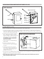
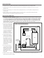
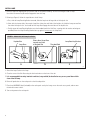
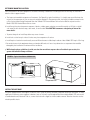
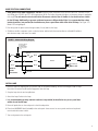
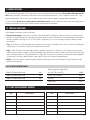
Ultraviolet Germicidal Lamps
Model 1952
24” Rooftop Unit
Model 1953
32” Rooftop Unit
Model 1972
Rooftop Unit, Internal Mount
Safety, Installation and Service Manual
Models 1952, 1953 & 1972
READ AND SAVE THIS MANUAL
TABLE OF CONTENTS
I. Safety Instructions . . . . . . . . . . . . . . . . . . . . . . . . . . . . . .2
IV. Annual Lamp Replacement . . . . . . . . . . . . . . . . . . . . .10
II. Application . . . . . . . . . . . . . . . . . . . . . . . . . . . . . . . . . . .3
V. Lamp Disposal . . . . . . . . . . . . . . . . . . . . . . . . . . . . . . . .11
III. Installation . . . . . . . . . . . . . . . . . . . . . . . . . . . . . . . . . . .3
VI. Troubleshooting . . . . . . . . . . . . . . . . . . . . . . . . . . . . . .11
Installation of External Mount Rooftop Units
(Models 1952 & 1953) . . . . . . . . . . . . . . . . . . . . . . . . . . . .4
VII. Lamp Replacement Record . . . . . . . . . . . . . . . . . . . .11
VIII. Limited Warranty . . . . . . . . . . . . . . . . . . . . . . . . . . . .12
Installation of Internal Mount Rooftop Units
(Model 1972) . . . . . . . . . . . . . . . . . . . . . . . . . . . . . . . . . . .7
I. SAFETY INSTRUCTIONS
Please read the safety and installation instructions carefully to help ensure a correct and SAFE installation of the
Aprilaire Ultraviolet Germicidal Lamp.
WARNING
Ultraviolet light is harmful to eyes
and skin. Never look at light produced
by this lamp. Shut off power to lamp
before servicing.
Electrical shock from 120 - 277 VAC
may cause serious injury. Shut off
power before starting installation and do
not turn power back on until complete.
Sharp edges may cause personal
injury. Use care when cutting and
handling sheet metal.
Lamp may cause personal injury in
the form of burns or cuts. Wear
protective gloves and safety glasses
when handling lamp. To prevent burns,
shut off power to lamp and allow to cool
for several minutes before servicing. If
lamp is broken, refer to lamp disposal
section of this manual.
2
CAUTION
UV light can cause color changes or structural degradation of
plastics, rubber, paper, and other non-metallic materials used in
the HVAC system.
• Install lamp in location that prevents exposure of plastics, rubber,
paper, and other non-metallic materials to UV light, or shield such
materials with aluminum tape, sheet metal, or metal conduit.
• Shield electrical wires that receive direct or reflected UV radiation
with aluminum tape, sheet metal, or conduit.
• Install lamp at least 8 inches away from equipment or components
made with UV resistant plastic. If equipment or components are not
made with UV resistant plastic – or if the UV resistance of the
material is unknown – shield with aluminum tape or sheet metal.
Water may damage lamp.
• Install lamp at least 3 inches away from evaporator coil.
• Do not install lamp below a humidifier or any source of water.
© Research Products Corp.
II. APPLICATION
Models 1952, 1953, and 1972 Aprilaire Ultraviolet Germicidal Lamps are designed for the treatment of evaporator coils used in
rooftop HVAC air handling units or in larger split systems used in the light commercial market. The UV germicidal light emitted from
the lamps will kill microorganisms growing on evaporator coils and drain pans and prevent further growth. The units use 120 -277
VAC / 60 Hz / single phase power, and are designed for continuous lamp operation.
External Mount Rooftop Units
Model 1952 24” Rooftop Unit
Model 1953 32” Rooftop Unit
The External Mount Rooftop Units incorporate a NEMA 4 enclosure for protection against the elements.
These units are intended primarily for installation on rooftop air handling units.
Internal Mount Rooftop Unit
Model 1972 Rooftop Unit, Internal Mount
The Internal Mount Rooftop Unit is intended primarily for rooftop applications in which it is preferred to mount the unit entirely within the
air handler rather than penetrating the outer cabinet. This unit is 18” in length and is mounted using supports supplied with the lamp.
III. INSTALLATION
NOTES FOR ALL MODELS
• The installation should be done by a licensed professional
trained in the installation and servicing of HVAC equipment.
Unit must be installed in accordance with all applicable
national and local codes.
• Read all safety instructions at the beginning of this manual.
Failure to do so could lead to personal injury and/or
equipment damage.
• Read the installation manuals for the equipment on which
the lamps are being installed for additional information
and warnings.
• In cases where fungi and/or bacteria are already present on
the evaporator coil, it is recommended that a qualified HVAC
service technician clean the coil before the installation of the
UV Lamp. Because the Aprilaire Ultraviolet Germicidal Lamp
quickly kills fungi and bacteria, there could be an initial period
of temporarily increased levels of airborne decay products if
the coil is not cleaned before installation.
• The tools and equipment required to complete this installation
include: Drill, drill bits (3/32 in. & ‘Unibit’), holecutter (2 in.),
Phillips screwdriver, #10 nut driver, tape measure, sealant,
aluminum tape, multimeter with clamp-on ammeter, alcohol
& wipes, and safety glasses. Some installations may also
require weatherproof conduit and conduit connectors.
• Shut off power to HVAC unit at the main disconnect
switch before starting installation.
APPROXIMATE COIL AREA COVERAGE FOR EACH MODEL
Coil Area
(sq. in.)
(sq. ft.)
Model 1972
18” Lamp
792
5.5
Model 1952
24” Lamp
1008
7.0
Model 1953
32” Lamp
1296
9.0
GUIDELINES FOR THE NUMBER OF LAMPS REQUIRED
FOR A GIVEN COIL AREA
Coil Area
(sq. in.)
(sq. ft.)
750
5.2
1000
6.9
1250
8.7
1500
10.4
1750
12.2
2000
13.9
2250
15.6
2500
17.4
2750
19.1
3000
20.8
3250
22.6
3500
24.3
Model 1972
18” Lamp
1
2
2
2
3
3
3
4
4
4
5
5
Model 1952
24” Lamp
1
1
2
2
2
2
3
3
3
3
4
4
Model 1953
32” Lamp
1
1
1
2
2
2
2
2
3
3
3
3
IMPORTANT NOTES: The above tables are guidelines only. The most
important requirement for an effective UV Lamp installation is complete
illumination of the coil and drain pan. Install UV Lamps as required to fully
illuminate the coil and drain pan.
The guidelines above are based on the following assumptions:
• UV Lamps to be installed 3 in. – 12 in. from coil
• Coil thickness in the range of 2 in. – 4 in.
3
INSTALLATION OF EXTERNAL MOUNT ROOFTOP UNITS (MODELS 1952 & 1953)
FIGURE 1 – Model 1952/1953
Safety Interlock Switch
Lamp
Unit Base
Ballast
Fuse
Lamp
Retaining
Bracket
Lamp Base
Lamp Socket
90-745
DETERMINE MOUNTING LOCATION
Determine a mounting location for the lamp. Use the criteria below to select a proper location:
a. The lamps are intended for evaporator coil treatment. See Figure 2 for typical installation. If a single Lamp cannot illuminate the
majority of the evaporator coil, two or more units might be required as shown. To the extent possible, the Lamp(s) should be centered
on the coil (or section thereof) being illuminated.
b. Install lamp in location that prevents exposure of
plastics, rubber, paper, and other non-metallic
materials to UV light, or shield such materials with
aluminum tape, sheet metal, or metal conduit.
See CAUTION statements at beginning of
manual for more details.
FIGURE 2 – Typical Installation of Model 1952/1953
c. To protect lamp, do not install lamp below any
source of water.
d. Install units so that Lamp is at least 3 in.,
but not more than 36 in., away from evaporator
coil surface.
e. Install lamp in a location that can be easily
accessed. Allow clearance to slide lamp in and
out of rooftop unit. Model 1952 lamp is 24 in.
and Model 1953 lamp is 32 in.
Blower
Evaporator Coil
f. Be certain the area in the equipment where you intend to drill and cut is free of any obstructions or components that would be
damaged by the installation or interfere with the installation.
g. While keeping these guidelines in mind, note that the more direct exposure the coil and drain pan receive, the
greater the benefit the lamps will have.
4
90-747
INSTALL THE UNIT BASE
1. Using the Unit Base as a guide, mark the locations for the lamp and mounting holes on the rooftop unit cabinet.
2. Carefully inspect the inside of the rooftop unit and make sure that no damage to any components will occur as a result of
drilling the holes.
3. Drill hole for the lamp using a 2 in. hole cutter. At the mounting hole locations, use 3/32 in. drill bit to make pilot holes for
mounting screws.
4. Apply weatherproof sealant (not provided) to the side of the Unit Base that is in contact with the rooftop unit housing.
Mount the Unit Base to the rooftop unit using #10 sheet metal screws.
MAKE ELECTRICAL CONNECTIONS
1. Verify power to the HVAC equipment is shut off. Determine where the power for the unit will come from. The units can use
any voltage from 120 VAC up to 277 VAC (single phase), 60 Hz. The ballast automatically adjusts to whatever voltage is supplied in
that range. The units must be wired such that the disconnect switch of the air handler is also the disconnect switch
for the UV lamp. Additionally, to prevent accidental exposure to UV germicidal light, it is recommended that safety
interlock switches (not provided) be installed on any access panel door within view of the UV lamp. See Figure 3 for
Model 1952/1953 wiring diagram.
2. Use the hole in the bottom of the
Unit Base and a corresponding
hole through the rooftop unit
housing for the electrical wiring.
Be certain the area in the rooftop
unit where you intend to drill and
cut is free of any obstructions or
components that would be
damaged by the installation or
interfere with the installation.
3. If space limitations prevent
running the wires through the
hole in the bottom of the Unit
Base, drill holes in the side of
the Unit Base as well as the
rooftop housing for watertight
conduit connectors. Install the
connectors and run conduit from
the Unit Base to the rooftop
unit penetration.
FIGURE 3 – Model 1952/1953 Wiring Diagram
Blue (2)
Red (2)
Lamp Socket
Interlock Switch
Ballast
Interlock switches
(not provided)
recommended for
all access panel
doors
3A Fuse
Black
4. Run wiring from the power
source through the conduit, if
applicable, and into the Unit.
Connect wiring to terminals
provided. Refer to wiring
diagram, Figure 3. Unit must
be grounded.
Yellow (2)
NOT USED
White
Black
Green
White
Green
120VAC to
277VAC
Power Source
Ground
90-753
5. Shield non-metallic components (such as electrical wires and fan belts) that receive direct or reflected UV radiation with
aluminum tape, sheet metal, or conduit.
5
INSTALL LAMP
1. Remove Lamp from shipping tube. Use ceramic ends of Lamp when handling – do not touch the glass tube of Lamp.
Use alcohol to remove any dirt and/or fingerprints from the Lamp.
2. Referring to Figure 4, follow the steps below to install Lamp:
a. First, with the Lamp Retaining Bracket removed, slide the Lamp into the large side of the keyhole slot.
b. Next, with the shorter side of the ceramic Lamp Base facing the small side of the keyhole slot, slide the Lamp over and into
the end of the keyhole slot. You should feel the Lamp Base engage the metal base of the keyhole slot.
c. Finally, return the Lamp Retaining Bracket onto the threaded stud of the Unit Base, securing with the washer and wing nut
provided. (Note: the Lamp Retaining Bracket butts up against, but not onto, the Lamp Base.)
FIGURE 4 – Model 1952/1953 Lamp Installation
Keyhole Slot
Lamp Base
a
Short side of Lamp Base
toward small side
of Keyhole Slot
Threaded Stud
b
Lamp Retaining Bracket
c
90-746
3. Attach the Lamp Socket to the Lamp.
4. Close the cover of the Unit Base using the latch mechanism on the front of the unit.
5. It is recommended that safety interlock switches (not provided) be installed on any access panel door within
view of the UV lamp.
6. Return all panel doors on the rooftop unit to their closed position.
7. Place three WARNING labels (included) on the rooftop unit: one by the Lamp, one on the main access panel, and one near
the main disconnect switch.
8. Turn on the power to the rooftop unit.
6
CHECK LAMP OPERATION
The preferred method for checking lamp operation is to measure the current draw of the lamp using a clamp-on ammeter. To detect
the low current of the UV lamp, the ammeter must be capable of measuring 100 mA and above. To prevent accidental exposure to
harmful UV germicidal light during this procedure, the location where the amperage measurement is taken must be in a
separate compartment from where the UV lamp is installed. To measure the current draw of the lamp:
a. First, shut off power to the HVAC equipment.
b. Next, in the control panel for the HVAC equipment, locate the hot and neutral wires that were installed to provide power to the lamp.
c. Place the clamp-on ammeter around either the hot or neutral wire. Make sure the ammeter is set to read amps in the mA range.
Again, make sure that the UV lamp – or light from it, if it were on – is not visible from where the ammeter is placed.
d. Next, turn the power to the HVAC equipment back on.
e. If the lamp has been installed correctly and is drawing power, the amp reading will be a minimum of 150 mA. For multiple lamps,
the reading would be a multiple of this value, i.e., with two lamps installed, the amp reading will be at least 300 mA.
f. If the lamp is operating correctly, remove the ammeter from the wiring and put back any access panels that were removed during
this procedure. If the lamp is not operating correctly, refer to the ‘Troubleshooting’ section of this manual.
Note: If other electrical components or accessories share the same circuit as the UV lamp(s), the current draw will be higher and the
above method may not be an accurate indication of lamp operation.
INSTALLATION OF INTERNAL MOUNT ROOFTOP UNITS (MODEL 1972)
FIGURE 5 – Model 1972
Wiring Access Cover
Lamp Socket
Lamp
Mounting Brackets
90-744
7
DETERMINE MOUNTING LOCATION
Verify that power to the HVAC equipment is off before continuing. To determine a mounting location for the lamp, use the criteria
below to select a proper location:
a. The lamps are intended for evaporator coil treatment. See Figure 6 for typical installations. If a single Lamp cannot illuminate the
majority of the evaporator coil, two or more units might be required. To the extent possible, the Lamp(s) should be centered on the
coil (or section thereof) being illuminated. Note that a Model 1972 Internal Mount Unit can be installed in conjunction with a
Model 1952/1953 External Mount Unit as shown.
b. Install lamp in location that prevents exposure of plastics, rubber, paper, and other non-metallic materials to UV light, or shield
such materials with aluminum tape, sheet metal, or metal conduit. See CAUTION statements at beginning of manual for
more details.
c. To protect lamp, do not install lamp below any source of water.
d. Install units so that Lamp is at least 3 inches away from evaporator coil surface.
e. Install lamp in a location that can be easily accessed. Allow clearance to slide lamp in and out of duct. Model 1972 lamp is 18 in. long.
f. Be certain the area in the equipment where you intend to drill and cut is free of any obstructions or components that would be
damaged by the installation or interfere with the installation.
g. While keeping these guidelines in mind, note that the more direct exposure the coil and drain pan receive, the
greater the benefit the lamps will have.
FIGURE 6 – Typical Installations of Model 1972
Blower
Evaporator Coil
90-749, 90-748
INSTALL THE UNIT BASE
Using the supplied brackets and supports, mount the unit to solid, non-moving structural components within the rooftop unit. As every
application is different, custom supports or brackets (such as ‘Unistrut’) may be required. Note that multiple Model 1972 units can be
assembled end-to-end, if desired. To do so, connect each unit with a nipple or similar conduit connector. Note that the units must be
wired in parallel circuits.
8
MAKE ELECTRICAL CONNECTIONS
1. Verify power to the HVAC equipment is shut off. Determine where the power for the unit will come from. The units can use
any voltage from 120 VAC up to 277 VAC (single phase), 60 Hz. The ballast automatically adjusts to whatever voltage is supplied in
that range. The units must be wired such that the disconnect switch of the air handler is also the disconnect switch
for the UV lamp. Additionally, to prevent accidental exposure to UV germicidal light, it is recommended that safety
interlock switches (not provided) be installed on any access panel door within view of the UV lamp. See Figure 7 for
Model 1972 wiring diagram.
2. Run wiring from the power source through conduit, if used, and into the Lamp.
3. Shield non-metallic components (such as electrical wires and fan belts) that receive direct or reflected UV radiation
with aluminum tape, sheet metal, or conduit.
FIGURE 7 – Model 1972 Wiring Diagram
Interlock switches
(not provided)
recommended for
all access panel
doors
3A Fuse
Black
Black
White
White
Green
Green
120VAC to
277VAC
Power Source
Red (2)
Ballast
Blue (2)
Lamp Socket
Yellow (2)
NOT USED
Ground
90-754
INSTALL LAMP
1. Remove Lamp from shipping tube. Use ceramic ends of Lamp when handling – do not touch the glass tube of Lamp.
Use alcohol to remove any dirt and/or fingerprints from the Lamp.
2. Snap the Lamp into the two Lamp Brackets.
3. Attach the Lamp Socket to the Lamp.
4. It is recommended that safety interlock switches (not provided) be installed on any access panel door
within view of the UV lamp.
5. Return all panel doors on the rooftop unit to their closed position.
6. Place three WARNING labels (included) on the rooftop unit: there are two for access panels and one to be placed
near the main disconnect switch.
7. Turn on the power to the rooftop unit.
9
CHECK LAMP OPERATION
The preferred method for checking lamp operation is to measure the current draw of the lamp using a clamp-on ammeter. To detect
the low current of the UV lamp, the ammeter must be capable of measuring 100 mA and above. To prevent accidental exposure to
harmful UV germicidal light during this procedure, the location where the amperage measurement is taken must be in a
separate compartment from where the UV lamp is installed. To measure the current draw of the lamp:
a. First, shut off power to the HVAC equipment.
b. Next, in the control panel for the HVAC equipment, locate the hot and neutral wires that were installed to provide power to the lamp.
c. Place the clamp-on ammeter around either the hot or neutral wire. Make sure the ammeter is set to read amps in the mA range.
Again, make sure that the UV lamp – or light from it, if it were on – is not visible from where the ammeter is placed.
d. Next, turn the power to the HVAC equipment back on.
e. If the lamp has been installed correctly and is drawing power, the amp reading will be a minimum of 150 mA. For multiple lamps,
the reading would be a multiple of this value, i.e., with two lamps installed, the amp reading will be at least 300 mA.
f. If the lamp is operating correctly, remove the ammeter from the wiring and put back any access panels that were removed during
this procedure. If the lamp is not operating correctly, refer to the ‘Troubleshooting’ section of this manual.
Note: If other electrical components or accessories share the same circuit as the UV lamp(s), the current draw will be higher and the
above method may not be an accurate indication of lamp operation.
IV. ANNUAL LAMP REPLACEMENT
The Aprilaire Ultraviolet Germicidal Lamp is designed for the lamp to be on at all times. After 9,000 hours of operation – 1 year of
constant use – the effectiveness of the lamp inside the unit diminishes and needs to be replaced. Rarely will a lamp burn out in one
year of continuous use; replacement is necessary because the lamp’s intensity decreases. Installation of the replacement lamp is best
handled by a qualified HVAC Service Contractor.
LAMP REPLACEMENT INSTRUCTIONS (EXTERNAL & INTERNAL MOUNT UNITS):
a. Shut off power to the rooftop unit. Wait several minutes for
lamp to cool before proceeding. Remove access panel(s) to
the rooftop unit.
b. Remove Lamp from Unit. For External Mount Units, open the
cover of the Unit Base, disconnect Lamp Retaining Bracket,
and slide the Lamp to the large side of the keyhole slot and
then pull straight out. For the Internal Mount Unit, simply
disconnect Lamp Socket and remove Lamp.
c. Use alcohol to remove any dirt and/or fingerprints from the
new Lamp. Insert Lamp into the unit and attach Lamp Socket
to the Lamp.
d. For External Mount Units, close and secure the cover of
Unit Base.
e. Put access panels of the rooftop unit back in place.
f. Turn power to rooftop unit back on.
g. Refer to ‘Check Lamp Operation’ of the previous section to
verify operation.
h. Record the date the lamp was replaced in this manual so
that the date for next replacement is clear.
Refer to ‘Troubleshooting’ section if the Lamp does not operate.
Under normal conditions, the Aprilaire Ultraviolet Germicidal Lamp should not require any maintenance other than annual lamp replacement.
10
V. LAMP DISPOSAL
As with a fluorescent light bulb, the UV lamp contains mercury and must be disposed of properly. Do not throw old lamps into the
trash. Many communities have agencies that take in mercury along with other materials – such as old paints, solvents, etc. – that
require special disposal. Please contact your municipal or county waste collection agency for proper disposal procedures.
If a lamp is broken, do not use a vacuum cleaner to pick up the waste. Instead, sweep up the waste into a plastic bag and seal.
Contact your municipal or county waste collection agency for proper disposal procedures.
VI. TROUBLESHOOTING
If the Lamp does not operate, check the following:
1. Electrical Connections – Verify that the Lamp has been wired correctly. The power to lamp must be always ‘on’ during normal
operation. On External Mount Units, verify that safety switch inside the cover of Unit Base has not been damaged. The voltage into
the units should be in the range of 120 - 277 VAC / 60 Hz / single phase. If it is not in that range, re-check the wiring or contact
an electrician.
2. Fuse – If the lamp is still not illuminated, turn off power to the rooftop unit, and check the Fuse. Look to see if Fuse is darkened or
visibly blown (i.e., wire broken) or check fuse continuity with multi-meter.
3. Lamp – Verify that Lamp is not broken and is properly seated into Lamp Socket. To check this, shut off power to the rooftop unit
and wait several minutes for lamp to cool before proceeding. Then remove access panels in order to look at Lamp. Verify that lamp
tube is not broken and that it is firmly pushed into its’ Lamp Socket. If necessary, use alcohol to remove any dirt and/or fingerprints
from the lamp. If the lamp is broken read the ‘Lamp Disposal’ section of this manual for proper disposal.
4. Ballast – If all of the above is okay, but the light still does not illuminate, the starter in the Ballast is likely shorted out and the
Ballast must be replaced.
LIST OF REPLACEMENT PARTS
Model 1952 Replacement Lamp
#94
Multi-Voltage High Output Ballast
(for 1952, 1953, and 1972)
#4466
Model 1953 Replacement Lamp
#96
Fuse (3 Amp, slow burn)
#4412
Model 1972 Replacement Lamp
#90
Fuse Cap
#4413
Lamp Socket
#4414
VII. LAMP REPLACEMENT RECORD
Date
Dealer Name
Date
Dealer Name
11
VIII. LIMITED WARRANTY
Your Research Products Corporation Aprilaire Ultraviolet Germicidal Lamp Model 1952, 1953 or 1972 is expressly warranted for three
(3) years from the date of installation to be free from defects. However the replaceable lamp is expressly warranted for only one (1)
year from the date of installation to be free of defects. Research Products Corporation’s exclusive obligation under this warranty shall
be to supply, without charge, a replacement for any part of the Ultraviolet Germicidal Lamp, which is found to be defective within a
three (3) year period (excluding Lamp which will be replaced if defective within one (1) year period) and which is returned no later
than thirty (30) days after the three (3) year period by you or your original supplier to Research Products Corporation, Madison,
WI53701, together with the model number and installation date of the Ultraviolet Lamp.
THIS WARRANTY SHALL NOT OBLIGATE RESEARCH PRODUCTS CORPORATION FOR ANY LABOR COSTS AND SHALL NOT APPLY TO
DEFECTS IN WORKMANSHIP OR MATERIALS FURNISHED BY YOUR INSTALLER AS CONTRASTED TO DEFECTS DISCOVERED IN THE
ULTRAVIOLET GERMICIDAL LAMP ITSELF.
IMPLIED WARRANTIES OF MERCHANTABILITY OR FITNESS FOR A PARTICULAR PURPOSE SHALL BE LIMITED IN DURATION TO THE
AFORESAID THREE-YEAR PERIOD. RESEARCH PRODUCTS CORPORATION’S LIABILITY FOR INCIDENTAL OR CONSEQUENTIAL
DAMAGES, OTHER THAN DAMAGES FOR PERSONAL INJURIES, RESULTING FROM ANY BREACH OF THE AFORESAID IMPLIED
WARRANTIES OR THE ABOVE LIMITED WARRANTY IS EXPRESSLY EXCLUDED. THIS LIMITED WARRANTY IS VOID IF DEFECT(S)
RESULT FROM FAILURE TO HAVE THIS UNIT INSTALLED BY A QUALIFIED HEATING AND AIR CONDITIONING CONTRACTOR. IF THE
LIMITED WARRANTY IS VOID DUE TO FAILURE TO USE A QUALIFIED CONTRACTOR, ALL DISCLAIMERS OF IMPLIED WARRANTIES
SHALL BE EFFECTIVE UPON INSTALLATION.
SOME STATES DO NOT ALLOW LIMITATIONS ON HOW LONG AN IMPLIED WARRANTY LASTS OR THE EXCLUSION OR LIMITATION
OF INCIDENTAL OR CONSEQUENTIAL DAMAGES SO THE ABOVE EXCLUSION OR LIMITATIONS MAY NOT APPLY TO YOU.
This warranty gives you specific legal rights and you may also have other rights, which vary, from state to state.
WARRANTY REGISTRATION
Please… Take a few minutes to visit us on-line at
www.aprilaire.com
to register your Aprilaire product.
If you do not have on-line access, please mail a postcard with your name, address, phone number,
product purchased and date of purchase to:
Research Products Corporation
P.O. BOX 1828
Madison, WI 53701
Thank you!
Your Warranty Registration information will not be sold or shared outside of this company.
1015 E. WASHINGTON AVE. • MADISON, WI 53703 • PHONE: 888/782-8638 • FAX: 608/257-4357 • www.aprilairecontractor.com
B2203283