1
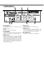
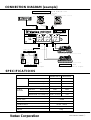
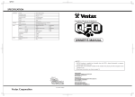
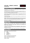
OWNER'S MANUAL
VESTAX CORPORATION
1-18-6 Wakabayashi, Setagaya-ku, Tokyo 154-0023 Japan
Phone:03-3412-7011 Fax: 03-3412-7013
Web:www.vestax.com
VESTAX (Europe)Ltd.
Unit 5 Riverwey Industrial Park Alton, Hampshire GU34 2QL England, U.K
Phone:(0)1420-83000 Fax: (0)1420-80040
Web:www.vestax.co.uk
Vestax Technical Center of America
8489 W.Third Street Ste.1044 Los Angeles CA 90048
Phone:1-323-801-2111 Fax:1-323-801-2112
Vestax Europe Technical Support
Rheinstr.213 D-53332 Bornheim Germany
Phone:49(0)2222-95-23-72 Fax:49(0)2222-95-23-74
CONGRATULATIONS!
The PCV-002 is a high profile mixer desigend to meet various professional requirements
of today's dance music DJ's. Please read this owner's manual carefully before you start
to use your mixer, so that you will fully understand all of the special features and enjoy
the full use of the product.
CONTENTS
C A U T I O N
IMPORTANT SAFEGUARDS
F E AT U R E S
CONTROLS AND FUNCTIONS
T O P PA N E L
How to change the fader unit
R E A R PA N E L
CONNECTION DIAGRAM
SPECIFICATIONS
…………………………………………………
…………………………………………………
…………………………………………………
…………………………………………………
……………………………………………………
……………………………………………………
……………………………………………………
……………………………………………………
……………………………………………………
CAUTION
RISK OF ELECTRIC SHOCK DO NOT OPEN
CAUTl0N:TO REDUCE THE RlSK OF ELECTRlC SHOCK
DO NOT REMOVE COVER(OR BACK)
NO USER-SERVICEABLE PARTS INSIDE
REFER SERVlCING T0 QUALIFIED SERVlCE PERSONNEL
The lightning flash with arrowhead symbol,within an equilateral triangle,is intended to
alert the user to the presence of uninsulated“dangerous voltage”within the product's
enclosure that may be of sufficient magnitude to consitute a risk of electric shock to persons.
The exclamation point within an equilateral triangle is intended to alert the user to the presence
of important operating and maintenance(servicing)instructions in the literature accompanying
the appliance.
T0 REDUCE THE RISK 0F FIRE 0R ELECTRlC SHOCK,DO NOT
EXPOSE THIS APPLIANCE T0 RAIN 0R M0ISTURE.
2
2
3
4
5
5
6
7
8
8
IMPORTANT SAFEGUARDS
READ BEFORE OPERATING EQUIPMENT
This product was designed and manufactured to meet
strict quality and safety standards. There are,
however, some installation and operation precautions
which you should be particularly aware of.
1. Read instructions-All the safety and
operating instructions should be read before
the appliance is operated.
9. This product should never be placed near or
over a radiator or heat register. This product
should not be placed in a built-in installation
such as a bookcase or rack unless proper
ventilation is provided or the manufacturer's
instructions have been adhered to.
2. Retain instructions-The safety and operating
instructions should be retained for future
reference.
3. Heed Warnings-All warnings on the 10. Power sources-This product should be
appliance and in the operating instructions
operated only from the type of power
should be adhered to.
source indicated on the marking label. If
you are not sure of the type of power supply
4. Follow Instructions-All operating and use
to your home, consult your appliance dealer
instructions should be followed.
or local power company.
5. Cleaning-Do not use liquid cleaners or 11. Lightning-For added protection of this
aerosol cleaners. Use a damp cloth for
product during a lightning storm, or when it
cleaning.
is left unattended and unused for long
periods of time, unplug it from the wall
6. Attachments-Do not use attachments not
outlet. This will prevent damage to the
recommended by the product manufacturer
product due to lightning and power-line
as they may cause hazards.
surges.
7. Water and Moisture-Do not use this product 12. Overloading-Do not overload wall outlets
near water-for example, near a bath tub,
and extension cords as this can result in a
wash bowl, kitchen sink, or laundry tub, in a
risk of fire or electric shock.
wet basement, or near a swimming pool,
and the like.
13. Object and Liquid Entry-Never push objects
of any kind into this product through
8. Accessories-Do not place this product on an
openings as they may touch dangerous
unstable cart, stand, tripod, or table. The
voltage points or short-out parts that could
product may fall, causing serious injury to a
result in a fire or electric shock. Never spill
child or adult, and serious damage to the
liquid of any kind on the product.
appliance. Use only with a cart,. stand,
tripod, bracket, or table recommended by 14. Servicing-Do not attempt to service product
the manufacturer, or sold with product. Any
yourself as opening or removing covers
mounting of the appliance should follow the
may expose you to dangerous voltage or
manufacturer's instructions, and should use
other hazards. Refer all servicing to
a mounting accessory recommended by the
qualified personnel.
manufacturer.
3
15. Damage Requiring Service-Unplug this 16. Replacement Parts-When replacement
product from the wall outlet and refer
parts are required, be sure the service
servicing to qualified service personnel
technician has used replacement parts
under the following conditions:
specified by the manufacturer or have the
same characteristics as the original parts.
a. When the power-supply cord or plug is
Unauthorized substitutions may result in
damaged.
fire, electric shock or other hazards.
b. If liquid has been spilled or objects have
fallen into the product.
17. Safety Check-Upon completion of any
c. If the product has been exposed to rain or
service or repairs to product, ask the
water.
service technician to perform safety checks
d. If the product dose not operate normally
to determine that the product is in proper
by following the operating instructions.
operating condition.
Adjust only those controls that are coverd
by the operating instructions as an 18. Carts and Stands-The appliance should be
improper adjustment of other, controls
used only with a cart stand that is
may result in damage and will often
recommended by manufacturer.
require extensive work by a qualified
technician to restore the product to its 19. An appliance and cart combination should
normal operation.
be moved with care. Quick stops, excessive
e. If the product has been dropped or cabinet
force, and uneven surfaces may cause the
has been damaged.
appliance and cart combination to overturn.
f. When the product exhibits a distinct
change in performance this indicates need
for service.
FEATURES
●The PCV-002 is equipped with 3 band ●The cross fader of the PCV-002 is the ultra
isolators on each channel, allowing DJs to
smooth CF-R US, which is the best quality
mix in the most creative way.
fader available in this class.
●The EQ curve has been refined by our ●To give young DJs all over the world a mixer
manufacturing team to offer the sweetest
that can grow with their career, the crosssounding, and most striking EQ available in
fader in the PCV-002 can be upgraded to the
any mixer at this price point.
most durable Vestax Pro-fader, CF-PCV, for
pro-level performance.
4
CONTROLS AND FUNCTIONS
TOP PANEL
3
2
4 1 4
2
3
9
13
10
11
12
5
5
6
7
8
q POWER LED
The LED is lit when power is on.
w INPUT SELECT SWITCH
Used to select the input (LINE or PHONO ) to be
sent to each PGM channel.
e TRIM CONTROL
Adjusts the input level of each channel.
r ISOLATOR (HI,MID,LOW)
Cuts and boosts each frequency range. The
level is flat when this knob is set at 12 o'clock.
t INPUT FADER
Used to adjust the input level of each program.
Usually set at the 7-8 position.
y INPUT LEVEL METER
The LED level meters indicate the input signal
level of each PGM channel.
u CROSS FADER
When the input level of PGM1 and PGM2 are
properly set, PGM1 will be heard with the cross
fader set to the left side. PGM2 will be heard
with the cross fader set to the right side. When the
cross fader is set in the center, both programs
will be heard. This is a detachable fader for the
ease of replacement with "CF-RUS" "CF-R" or
"CF-PCV" when it is worn out.
i PHONES JACK
Use this jack to connect the head phones. Head
phones from 8 ohm to 600 ohm can be used.
150 ohm is recommended.
o MASTER LEVEL
Adjusts the signal level output from the LINE
OUT jack on the rear panel.
!0 MASTER BALANCE
Adjusts the signal balance of the left and right
side of the outputs from the LINE OUT jack on the
rear panel.
!1 MONITOR LEVEL
Adjusts the head phone output level.
!2 MONITOR SELECT FADER
When the monitor levels of PGM1 and PGM2
are properly set, PGM1 will be monitored in the
headphone with the fader set to the left side and
PGM2 will be monitored in the head phone with the
fader set to the rigth side. When the fader is set in
the center, both programs will be monitored in
the head phone.
!3 MIC LEVEL
Adjusts the input level from all microphone
inputs.
5
How to change the fader unit.
■HOW TO REMOVE THE TOP PANEL
driver
1 Remove all fader knobs and the 4screws which
○
fix the top panel.(see fig.A)
2 Remove the top panel.
○
■HOW TO CHANGE THE FADER UNIT
1 Remove the screws on the fader panel.(see fig.B)
○
2 Remove the fader unit from position in mixer.
○
3 Carefully remove the multi-cable connector from
○
fader unit.(see fig.C)
4 Attach multi-cable connector to new fader unit.
○
5 Position the fader unit carefully and secure with
○
screws.
Remove the multi-cable
マルチケーブル
connector from fader unit.
コネクターを抜く
fig.A
driver
角4点のネジを外す。
Remove four scews.
fig.C
You can replace the CF unit with "CF-RUS",
"CF-R" or "CF-PCV".
■HOW TO REPLACE THE CF UNIT WITH "CF-PCV"
When the fader unit is replaced, please see fig.C.
Place the fader unit in the proper position and fix it
b)
with two screws.(fig.D-○
fig.B
CAUTION
There is a swith for "CF-PCV" unit. When "CFPCV" unit is installed, set the switch to "PCV"
mode.
CAUTION
When the fader unit is replaced, do not loosen
the screws with marking.
fig.D
6
CF-RUS or CF-R
CF-PCV
REAR PANEL
19
18
17
RISK OF ELECTRIC
SHOCK. DO NOT OPEN
WARNING;SHOCK HAZARD-DO NOT OPEN.
AVIS;RISQUE DE CHOC ELELCTRIQUE -NE PAS OUVRIR.
OUTPUT
MADE IN CHINA UNDER LICENCE OF VESTAX TOKYO, JAPAN
SERIAL NO.
DC IN
POWER
DC15V
PGM 2
PGM 1
MIC
REC
LINE 2
LINE 1
LINE
PHONO 2
PHONO 1
R
L
R
L
L
R
GND
14 15
16
20
!4 POWER SWITCH
!8 INPUT JACK 2
The POWER LED that is located on the top
Used for PGM2 input. Connect as for !7.
panel is lit when on.
!9 OUTPUT JACK
!5 DC IN
Connect to the input of a power amplifier. You
Connect to the DC-15 AC adapter.
can also use another LINE OUT when you need
to have an output besides the main output.
!6 GND TERMINAL
Connect this terminal to the ground lead of the @0 MIC INPUT JACK
turntable. This helps to reduce noise and hum.
Input jacks of connection of a microphone.
!7 INPUT JACK 1
Used for PGM1 input. Connect turntable
equipped with a MM pickup cartridge to PHONO
input. CD players, tape decks, DATs, MDs etc.,
should be connected to LINE input. Line level
musical instruments with stereo outputs such as
Rhythm Machines or Samplers should also be
connected to line inputs.
7
CONNECTION DIAGRAM [example]
CD, MD player, TAPE DECK etc
Connect to line input
CDPLAYER[eg.VESTAX CDX-35]
CDPLAYER[eg.VESTAX CDX-35]
TAPE RECORDER, CD, MD, DAT, etc.
SEARCH
TRACK
MIN
SEC
PITCH
KEY
REPEAT
FRM
OPEN/
CLOSE
DISPLAY
STOP
LOCATE
POINT FOCUS
ENTER
1
2
REVERSE
3
LOOP
A
PLAY/PAUSE
CUE
MONITOR
START
END
B
RELOOP/EXIT
PLAY/PAUSE
CUE
LINE1
LINE2
REC OUT
RISK OF ELECTRIC
SHOCK. DO NOT OPEN
WARNING;SHOCK HAZARD-DO NOT OPEN.
AVIS;RISQUE DE CHOC ELELCTRIQUE -NE PAS OUVRIR.
OUTPUT
MADE IN CHINA UNDER LICENCE OF VESTAX TOKYO, JAPAN
SERIAL NO.
DC IN
POWER
DC15V
PGM 2
PGM 1
MIC
REC
LINE 2
LINE 1
LINE
PHONO 2
PHONO 1
R
L
R
L
R
L
GND
GND
LINE OUT
GND
PHONO2PHONO1
POWER AMPLIFIER[eg.VESTAX PT-X1000A]
CHANNEL A
MINI
MAX
CHANNEL B
MINI
PROTECT
MAX
B.T.L
POWER
PEAK
PEAK
POWER
INPUT
INPUT
ON / OFF
TURNTABLE[eg.VESTAX PDX-2000]
MAIN SPEAKER
MAIN SPEAKER
TURNTABLE[eg.VESTAX PDX-2000]
TURNTABLE
AMPLIFIER
Connect to phono input
Connect to output
S P E C I F I C AT I O N S
NOMINAL INPUT
IMPEDANCE
INPUT SECTION PHONO 1, 2(RCA PIN JACK)
-42dBv
470KΩ
LINE 1, 2 (RCA PIN JACK)
-10dBv
470KΩ
MIC (1/4" PHONE JACK)
-54dBv
3.3KΩ
NOMINAL OUTPUT
IMPEDANCE
0dBv
220Ω
MAXIMUM OUTPUT
IMPEDANCE
OUTPUT
SECTION
LINE OUT (RCA JACK)
HEADPHONE(1/4" PHONE JACK) 70mW(47Ωload)
FREQUENCY RESPONSE
20Hz ∼ 20KHz
CROSS TALK
>100dB
S/N RATIO
<-82dB
POWER SUPPLY
DIMENSIONS
(W×H×D)
WEIGHT
Vestax Corporation
>8Ω
DC15V 500mA
248×105×261
(mm)
3.5kg
MAY.2002 PCV002E q