1
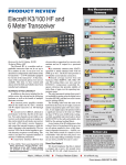
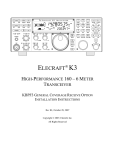
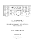
Elecraft K3 vs. ICOM IC-781
vs. Kenwood TS-850:
Comparative Measurements and Experience
Version 1.1
Matthias Jelen, DK4YJ
Ben Büttner, DL6RAI
Toby Deinhardt, DD5FZ
January 21, 2008
1 Introduction
by Matthias Jelen, DK4YJ
Toby, DD5FZ, was kind enough to lend me his brand new K3 over Christmas. Which gave me time to play
around with the rig. The first impression of the radio’s acoustic properties at DK0MN (our club station) and
in my own shack were very positive. Because Elecraft is cocky enough to assert that the K3 is as good,
if not better, than Japanese rigs in the 10ke category, I wanted to find out how accurate their claims are.
Unfortunately I did not have a 10,000 e rig, so I used my father’s (DL3MII) IC-781 as a reference. The
IC-781 is not the newest, but, for good reasons, its RX enjoys a good reputation.
I measured the MDS, IP3 using the same methods as the ARRL uses for their tests. I also did a (kind of)
relative phase noise measurement. All measurements were performed at 14.1 MHz. The other bands would
also have been interesting, but the ARRL will surely be doing this soon.
The ARRL measures IP3 as follows:
1. A "Two Tone Signal" source is connected to the RX.
2. Each signal is adjusted so that each signal causes the s-meter to display S5. These levels are used the
reference level (Pref ).
3. The RX is tuned to the frequency where the expected intermodulation product should be.
4. The level of both signals is raised until the intermodulation product reaches S5. This level is Pimd .
The IP3 is calculated using the following:
IP3 =
−Pref + 3Pimd
2
1
S5 is, of course, an arbitrary reference level and any other level could be used as Pref. My experience is that
the S5 method tends to be somewhat more optimistic than low level methods, e.g. a 3dB signal above noise.
IMDR3 can be calculated using MDS and IP3 :
IMDR3 =
IP3 − MDS
1, 5
2 Results
The rigs were set to CW mode for all measurements. The IC-781 used its 500Hz Filter and the K3 was set
400Hz because Toby had installed the 400Hz roofing filter and we wanted to use its advantage.
2.1 MDS
Table 1 shows the sensitivity limits of the rigs at 14.1MHz with and without the preamplifier.
TRX
IC-781 (500 Hz)
K3 (400 Hz)
w Preamp
-141 dBm
-138 dBm
w/o preamp
-133 dBm
-134 dBm
Table 1: MDS in mode CW
Both rigs have enough sensitivity. Conspicuous is the minimal MDS improvement with the K3’s preamplifier.
I would think, that in real life one would not turn the preamp on very often.
2.2 IP3
Figure 1 shows the progression of IP3 and IMDR33 for various signal intervals. Measurements were made at
100, 50, 20, 15, 10, 5 and 2 kHz. The curves "‘oben"’ (above) and "‘unten"’ (below) show the strength of
the intermodulation (IP3 ) product above and below 14.1 MHz. It is interesting that the IC-781 products are
asymmetrical.
It is conspicuous that below 15 kHz the IC-781 shows a drastic deterioration. The K3 profits strongly from
its narrow roofing filter, and behaves like a "textbook case". With strong neighboring signals, the K3 should
have less problems than rigs with FM bandwidth early filtering.
2.3 Phase Noise
Phase noise is very difficult measure accurately with a hobby laboratory. For this reason, I only did a relative
measurement of the noise level while tuning closer and closer to a very strong signal. The 14.1 MHz, 0dBm,
low noise test signal was produced by a HP8640. The RX was tuned from 14.6MHz to 14.101MHz using 250
logarithmic steps. At each step the AF output noise level was measured.
The curves in figure 2 should give one an idea how close to a strong signal one can still operate in a sensible
fashion, assuming that the signals are clean. In reality most signals are not very clean.
2
IP3 vs. Trägerabstand
IMDR3 vs. Trägerabstand
35
115
30
110
25
105
IMDR3 [dBm]
IP3 [dBm]
20
15
10
5
0
95
90
781 (oben)
781 (unten)
K3 (oben)
K3 (unten)
−5
−10
−15
100
0
20
40
60
Abstand der Signale [kHz]
80
781 (oben)
781 (unten)
K3 (oben)
K3 (unten)
85
80
100
0
20
40
60
Abstand der Signale [kHz]
80
100
Figure 1: IP3 and IMDR3 for different frequency offsets of the two signals
Rauschanstieg bei Annäherung an 0 dBm auf 14.1 MHz
45
IC781 DL3MII
K3 DD5FZ
40
Rauschanstieg [dB]
35
30
25
20
15
10
5
0
3
10
4
5
10
10
6
10
Frequenzoffset [Hz]
Figure 2: Phase noise increase while approaching a strong signal
3 Conclusions
The receiver measurements of the K3 look very good. Such measurements should not and can not replace real
experience in a contest environment. However I see no reason why the K3 should not perform well.
All measurements were done to the best of my expertise and with care. I feel that all measured values are
reasonably accurate. However, as always, there may be overlooked errors.
3
4 Practical Experience
by Ben Büttner, DL6RAI
Toby also lent me his new rig for about a fortnight during the first days of 2008. I used this chance to spend
many concentrated hours with the K3. I am the owner of 4 Kenwood TS-850 transceivers, one of which is
used a source of parts for the other three. Nonetheless these rigs are slowly becoming very dated, and I have
been looking for a persuasive ersatz for some time now. Up to now, my search has been unsuccessful, but the
K3 gives me hope.
Figure 3: Front panel of the Elecraft K3 Transceiver
When I compare the K3 with DL2NBU’s (a leading contester in the Bavarian Contest Club) "Survey about
Contest Radios" from 2004 [1], it seems as though Elecraft read the results and implemented them, because
there is nothing on this 4 year old wish list which is missing!
4.1 Front Panel
The front panel (see figure 3) is after a short familiarization very clear. The optical design of this transceiver
has been kept rather simple. This is a plus point in my opinion.
All of the important control elements for contest operating are easily reached. For me these include:
• VFO, A/B switching, memories, band switching and RIT
• AF volume and RF gain
• Filter employment (Hooray, no more cyclic switching)
• AGC slow, fast and off (important for many QRN situations)
• VOX/QSK switching and VOX delay adjustment
• CW sidetone (frequency and volume) as well as SSB monitor volume
4
The continuously adjustable IF filtering (shift/width) with automatic roofing filter switching is the hit, during
contest operations, for fighting QRM or fishing out a weak signal while searching and pouncing.
Fast QSY: One can configure the K3 so that the RIT knob functions as a high speed VFO knob, when the RIT
is not in use. In this mode the RIT knob behaves a bit like the M.CH knob on the TS-850. This may also be
source for errors, when the OP bumps the knob by mistake. Time will tell if this works well.
Pushing the Band Up and Band Down buttons does not always bring one to the next amateur radio band. After
a series of "random" button pushes and knob twists, I suddenly had the following series of bands: 160m, 20m,
60m, 40m, 30m, 20m, 17m, 15m, 12m, 10m, 6m. The 80m band had disappeared. As Toby explained to me,
this can occur when the A and B VFOs are not set to frequencies in the same band. When one presses the A/B
button, then a band can "disappear". A further effect is, that when one rotates the small VFO B knob, which
next to the large and very comfortable VFO A knob, the front end filters for the VFO B band are switched in
but the receiver stays on the VFO A band. The relais click and the the receiver is suddenly almost deaf. When
one rotates the VFO A knob, the filters switch back to the correct band and everything is back to normal. It
took me awhile to understand what was going on. This bit strangeness should be fixed in a future version of
the firmware.
When operating in split mode the TX frequency is not distinctly displayed. One feels uncertain if one is really
transmitting on the correct frequency. It would be nice if the large frequency display, would display the TX
frequency while transmitting.
4.2 The Rear
Figure 4: Rear of the Elecraft K3 Transceivers
The connectors on the rear side of the K3 (figure 4) come pleasingly close to fulfilling the Bavarian Contest
Club standard:
• Foot switch: RCA socket.
• CW Key: 6.3mm phone sockets for straight key & paddles; paddles have priority.
• Loud speaker: 3.5mm phone socket.
• PA Relay: RCA socket.
• Very useful is the 12V RCA socket, e.g. to provide a transceiver interface with power.
5
• For the RX antenna and transverter: BNC, a very good choice, experience has shown RCA a poor choice
for RF.
The RS-232 interface for the transceiver control is built in, in other words all one needs is a serial cable to
connect the K3 to a computer.
One nice thing about the K3’s RS-232 interface: While turning the VFO knob the frequency information is
updated continuously. The TS-850 does not do this. It waits c. 1 second after the knob movement has ceased
before communicating the correct frequency.
The two input jacks for CW can for example be used for automatic CW keying by an external computer while
the second jack is connected a paddles key, e.g. a Bencher BY1. Finally a rig with a built in, clean solution
for doing this! As soon as one starts keying with the paddles, the other key input is ignored, in other words no
more alphabet soup. A really cool feature. I’ve been told that ICOM radios have had this feature for quite a
while now.
4.3 CW-Mode
For all intents and purposes the CW mode is always a kind of QSK, even when one activates Semi-BK. The
PTT control output for PA can be configured with a delay. Some people will probably prefer this. I, however,
would like to have the choice of turning off the noise between characters. During CW contests, at times, I go
as far as turning off the side tone, or reducing its volume to a minimum, to give my ears a short rest every time
I transmit.
For people without absolute hearing there is a CW tuning display (CWT), to help one tune to the middle of
the filter. This must be turned on a band by band basis. There are, by the way, many features in the K3 are
turned on or off per band, e.g. CW/CW-R. I am used to listening to CW using the lower side band, in other
words, while tuning from a lower frequency to higher frequency, at first I hear high pitched a high audio tone,
which decreases as I move up the band. This is CW-R on the K3.
4.4 SSB
I did not spend much time doing SSB, so only a few short comments:
• When switching from CW to SSB in the same band, one must adjust the filters per hand;
• The SSB modulation does not have enough punch, is not penetrating enough;
• The microphone socket (front panel): The pin outs are ok for dynamic Kenwood microphones but not
for electret microphones. The microphone voltage supply is on K3 pin 6 and the TS-850 uses pin 5.
This means existing microphone cables for Kenwood may need to be modified.
4.5 RTTY
The RTTY mode mode is straightforward and simple to use. The frequency display in DATA mode is correct
for the mark frequency, which is important for DX spotting. The dual pass band feature for RTTY is also very
nice. This is a narrow filter with two small maxima for the mark and space frequencies.
6
4.6 Antenna Tuner
I tested the K3’s tuner with my puny 2x 13m dipole and 300 Ω twinline feeder on all (German) bands except
160m. The tuner in the TS-850 can handle this without any problems, and remembers the tuning values in
100 kHz steps.
The K3 also has an intelligent tuner with memory but only saves one set of values per band and not in the
100 kHz steps I am used to from the TS-850. This means that one may need to retune more than once when
moving around a band.
I also found what I think may be a bug in the firmware. If the tuner can not get the SWR down to about 1:1
the transmission power does not fold back. The Elecraft tuner only managed to reach a SWR 2.3:1 on the
80m band with my antenna. The K3 appeared, according to the its display, to continue transmitting with a full
power of 100W. I could not measure the output power directly, but the power supply current also showed no
sign of folding back. Possibly the K3’s 100W PA is robust enough to handle this. It survived this unintentional
test with no problems.
4.7 Resumè
The K3 left me with a very positive impression and can easily imagine that this rig could end the TS-850
dynasty in my shack.
One last interesting aspect were the release notes of the new firmware MCU 1.58 and DSP 1.481 .
"NEW 100- AND 50-Hz DSP FILTERS: Weâ200231ve completed the addition of high-performance
100- and 50-Hz "FIR" (finite impulse response) DSP filters. These are flatter than the original
"IIR" (infinite impulse response) filters, and exhibit less ringing..."
New filters are available in software! Instead of grabbing a screwdriver to install the new filters, all one needs
to do is connect a serial cable and start a programm to upload the firmware. It may take a while to get used
to this new modern paradigma. It does show the potential which is still in this rig and the kinds of features
which can be added to this software defined radio long after delivery.
We will be running the K3 parallel to a Kenwood TS-850 during the CQWWDX 160m contest. This will
provide us with new and interesting insights.
1I
would like to point out that when this version of the firmware was released, Ben had already returned my K3 to me - Toby
7
5 The Proud Owner
by Toby Deinhardt, DD5FZ
5.1 Introduction
I would like to use this chance to thank Ben and Matthias for the time and effort it took to write about their
impressions. This was one of the reasons I ordered my K3 very early, because my gut told me, this was going
to be a very interesting radio, and worth taking a close look at within the Bavarian Contest Club [2].
Also, I wanted to have a good radio for myself.
You may wonder why I refer to this as version 1.1. The three of us hope during the next several weeks to add
further measurements and new insights as we gain experience using the K3 in the upcoming major contests.
At the present time, we plan for Ben and Matthias, both excellent CW operators, to be in the CQWWDX
160m contest and I plan to use the K3 in RTTY WPX, which should interesting. My last RTTY QSO is at
least 20 years in the past. Also at least one of us, using the K3, will be QRV during CQ 160m SSB, ARRL
International DX, Russian DX etc. contests. In other words, as the K3 firmware evolves and we learn more
about the radio, we will be updating this document.
5.2 The K3 Configuration
My K3 during the tests for version 1.1 had the following configuration:
K3/100
KAT3
KFL3A-400
KFL3A-1.8K
KFL3A-2.1K
KFL3A-2.7K
KFL3A-6K
KXV3
100W Transceiver (Modular Kit) with standard TCXO
Internal ATU with 2nd Ant. Jack
400 Hz, 8-pole roofing filter
1.8 kHz, 8-pole roofing filter
2.1 kHz, 8-pole roofing filter
2.7 kHz, 5-pole filter (standard filter included with the K3)
6 kHz, 8-pole roofing filter
Transverter Interface w/ RX Ant. I/O
Table 2: K3 configuration for tests
The firmware was updated more than once during the test period, so some of the comments in this document
may be referring to features or bugs which have since been fixed or changed.
I still have the following items on back order or have not installed them yet:
KBPF3
KRX3
KFL3A-400
KFL3A-1.8K
KFL3A-2.1K
KFL3A-2.7K
KFL3B-FM
KDVR3
General Coverage RX Front End Filters
High Performance Subreceiver
400 Hz, 8-pole roofing filter (for the KRX3)
1.8 kHz, 8-pole roofing filter (for the KRX3)
2.1 kHz, 8-pole roofing filter (for the KRX3)
2.7 kHz, 5-pole filter (standard filter included with the KRX3)
FM b/w, 8-pole roofing filter
Digital Voice Recorder
Table 3: K3 options not yet installed
8
The final configuration will see the KBPF3 installed on the secondary RX and I will move the 6 kHz filter
from the main to the secondary receiver, allowing me to install the FM filter in the main RX.
There has been much discussion on the Elecraft reflector over the last 9 months about which configurations
make sense and which do not. Mostly this has dealt with which roofing filters are needed. Briefly, my
configuration was based upon the following thoughts:
• As my landlord does not allow the installation of any antennas, I often operate from vacation QTHs
such as 5B, SV, 4O, CU etc. The fewer boxes needed the easier the journey. In the past my K2s have
mostly performed very well in this role.
• I am and never was very good at CW. The frustration of practicing with a computer for an admittedly
wonderful mode which I could not use on a daily basis (see above) made me eventually stop. This
means most of my operation is in SSB.
• I actually enjoy SSB contesting!
• When traveling, I wanted to have good AM reception of international broadcasters.
• In the past one aspect of the TS-850 which has been a real disadvantage is the lack of a second RX,
especially when working NA and EU at the same time on 40m and 80m.
I know that some of my readers will feel that installing 1.8 kHz and 2.1 kHz in the K3 is overkill and will
not bring any real improvement. This may or may not be correct, but my experience has been, every tiny
little bit helps when fighting it out in the European zoo on 40m during large contests. Even if the advantage
is mainly psychological, I suspect that this will still mean a few QSOs more on 40 with both filters. QSOs,
which wouldn’t have been possible with only one.
When considering which filters to install in a K3, remember that the main selection takes place in the DSP
and the roofing filters are there to protect the ADC, IF amps and second mixer, which by the way is not a high
end mixer like the first mixer. These means low distortion and the first 30 or so dBs are important, and not so
much the ultimate rejection.
5.3 The K3 Build
I am writing this several weeks after the build, so the details may be hazy.
I bought the K3 as a so called no solder kit. This means no solder to melt, no torroids to wind, no burnt
fingers (always brings me luck when building things... hi) and almost nothing to align. It also means about
a hundred things to screw together, plugging things into each other, searching for small bits and pieces (this
hasn’t changed) and a much shorter build time.
My K3 arrived exactly 200 days, almost to the hour, after my initial fax to Elecraft. That evening I went from
work directly to DKØMN, our club station in Munich [3]. By the way, my box was brown and not white.
I quickly unpacked everything, and, with boxes in boxes and much padding, found no damage. Because I had
read the construction manual [4] several times before the K3 had arrived , I immediately started to build the
K3. I tend to think that inventories are for sissies and up to now Elecraft’s track record was very good.
The quality of the boards is top notch, a feast for the eyes and things were going along well. The assembly
manual was just the thing for mechanical klutzes like myself. Yep, I was zipping along, reading the fortune
cookies (the small bags with parts and a piece of paper saying this assembly was done by ...) and being amazed
that so many bits and pieces were evolving quickly into a cool radio, when, all of a sudden, the manual wants
me to install the TCXO.
9
Now, I knew I had seen the fortune cookie with TXCO board, and it was where I had left it, but, that’s funny,
no TXCO in the bag, only the board.
**PANIC**
Oh my god, I’ve lost one of the most important parts. After about an hour of searching a 5m x 4m room, I
concluded that Elecraft had actually made a mistake. A short telephone call with Scott in Aptos and an email
later my TXCO was in the mail. Kudos for the quick reaction. But it gets worse. The next morning (Friday) on
my way to work, sitting in the subway, I was doing a sissy thing, a mental inventory, when I realized that I had
not seen my KBPF3 anywhere. Another email was sent to Elecraft informing them, there was the possibility
that another part was missing. On Saturday, back to DK0MN, spend another hour or so searching, confirm
that Elecraft had also forgotten to ship this and return home feeling a bit miffed.
However when I turn on my computer, I find the following in a mail from Elecraft: "I sent the KBPF3
yesterday. I know you weren’t sure, but when I checked the paperwork here it look likely it was missing so
rather than delay over the weekend I went ahead and sent it so that you could have it."
They actually sent me a replacement for a part which only might have been missing! I thinks this says a lot
about a company and how seriously they take customer support.
As soon as the missing parts arrived, it took about a week, I finished the assembly of my K3.
On the whole the construction went without a hitch but could have been more streamlined, which by the way
has been improved in the newer versions of the manual. There were no glaring errors and when Elecraft says
something might be a tight fit, they really mean it; I was worried I was going to damage my main board while
installing the 100W PA. It is also worth noting that the number of wires which have to installed is minimal,
leading to a very tidy inside appearance.
5.4 K3 Gripes
Most of these are on Elecraft’s to do list and will be fixed "soon".
• You can not use more than one audio input at a time. A bummer when you want to work with an external
voice keyer. This is currently being worked on in Aptos.
• The missing band syndrome. More about this later (see part 6).
• Lousy KUSB drivers. I had at lot of problems updating the firmware and with WinTest using the old
drivers. If you order the KUSB, which is a very nice USB to serial interface, then do not use drivers on
the CD! Go to the Prolific website [5] and get the newest drivers. Elecraft also now recommends this.
The CD, by the way, is one of those miniature CDs which many drives can not handle.
• I also have the feeling that the SSB modulation could be "more powerful", but have not taken enough
time to try enough settings of the TX equalizer, compression, mic gain, etc. On the other hand, it
appears impossible to make the K3 sound "bad". But, on the other other hand, a tiny bit of "badness"
during contests is not that bad.
• My old MH2 microphone does not work well with the K3. When I push the PTT there is a very short
noise spike with a very high tone. It takes the ALC several seconds to recover from this. According
to Gary from Elecraft, they wanted to look into this, and I have not tried using this microphone since
November, so this might be fixed now. With my headset and foot switch this has never happened.
• I wish Elecraft had not moved the AF gain knob. It does take a bit of getting used to. Originally the AF
gain was below the RF gain, instead of the other way round. By the way, many of the pictures of the
K3, including the one in this document, are from prototypes before the knob switch occurred.
10
5.5 K3 Praise
• The radio is easy to use and if you come from a K2, the tap and hold philosophy and the radio itself are
almost instantly understandable. Nonetheless, it is well worth your while to study the manuals.
• The RX is eerily silent. I have always found the TS-850 very tiring because of the high level of audio
noise. This also applies to many other radios by Kenwood and Yaesu. I have not used many ICOMs so
I can not make a comparison to their radios. This was a big plus during the ARRL 10m contest here
in Germany. The conditions were terrible and the signals very weak. With tired ears I could not have
worked some of the stations I did work. The K2 is also an ear friendly radio.
• Continuous bandwith, shift, low- and high-cut filter tuning is just plain cool. Especially when it works
as well as it does in the K3.
• The DSP code does not sound like many digital radios: No artifacts and almost like a really good analog
sound.
• I actually had a CW QSO during Stew Perry! I know that for most of you this does not sound special,
but for me it was. It was a great idea to add various decoders to the firmware.
6 Elecraft says
Wayne, N6KR and chief designer of the K3, knew that we were working on this report, and asked me to give
him a chance to see the report at an early stage, so that he could point out errors, fix anything which might
be broken and make comments. I have been glad to do this. The below is a summary, at time paraphrased by
myself, of some of our discussions.
Wayne: We’ve also developed a couple of simple hardware modifications that you will probably want to add
to any test unit. One corrects the "soft" keying in CW mode. The other increases the onset point of hardware
AGC, which can help when you’re using a DSP bandwidth that’s narrower than the crystal filter.
Toby:We will be doing these modifications and we will add our results to this report.
Wayne: The K3 has a fairly low-gain preamp. It is designed to improve MDS to -136 dBm or better without
compromising dynamic range any more than necessary. Your later tests show that it is working as intended.
I should mention that we also have an external K3 6-meter preamp product in the testing phase right now. It
attaches directly to the RX ANT IN and OUT jacks, which can be selected on a per-band basis. It improves
6-meter MDS to better than -142 dBm.
Matthias: Phase noise is very difficult measure accurately with a hobby laboratory...
Wayne: I suspect the hump near 10 kHz is a byproduct of test equipment. In all of our tests, phase noise
decreases monotonically, reaching a limit of better than -150 dBc/Hz. If you have a synthesizer module you’d
like us to test, feel free to send it to us.
Wayne: Eric, just in case, I think we should arrange a synth module swap. This is important because low
phase noise is a hallmark of the K3 and one reason for the excellent dynamic range.
Matthias: Before swapping the module, I’ll ask at work. We have a fairly new phase noise measurement
system and I might be able to use it to check the present synthesizer directly.
Ben: Pushing the Band Up and Band Down buttons does not always bring one to the next amateur radio
band...
Toby: The missing band syndrome...
11
Wayne: I’m surprised that this occured. Recent firmware revisions should have cleaned up this behavior in
general. There are still some issues remaining in wide-range tuning of the VFOs, and I’m working on those. I
suggest you use FREQ ENT to re-set the VFOs within each ham band, and to load the latest firmware.
7 Change History
Version 1.1 Added sections "‘The Proud Owner"´ and "‘Elecraft Says"’. Produced an English version of
the document. A few typographic corrections.
References
[1] A Survey about Contest Radios, by Peter Pfann, DL2NBU at the 2004 H3K Meeting of the BCC,
http://www.bavarian-contest-club.de/history/2004/80,84.html
[2] Website of the Bavarian Contest Club: http://www.bavarian-contest-club.de
[3] Website of the DARC OV C12, Munich North: http://www.ov-c12.de
[4] K3 Construction Manual, see http://www.elecraft.com/K2_Manual_Download_Page.htm#K3.
[5] Prolific Website: http://www.prolific.com.tw
12