1
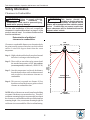
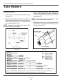
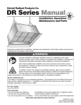
Tube Heater Installation, Operation, Maintenance and Parts Manual
! WARNING: This heater must be installed and serviced by trained gas installation and service personnel only!
Improper installation, adjustment, alteration, service or maintenance can cause property damage, injury or death.
Read the installation, operating and maintenance instructions thoroughly before installing or servicing this equipment.
Protect yourself and others by observing all safety information. Retain instructions for future reference.
Tube Heater
General Manual
FOR YOUR SAFETY
Do not store or use gasoline or other flammable
vapors and liquids in the vicinity of this or any other
appliances.
Description
Tube heaters are gas-fired infrared heaters designed
to provide comfort heat. They consist of three (3)
main components: a burner control box, radiant tube,
and reflector assembly. The heaters are typically
suspended from the ceiling by chains and controlled
by a thermostat. They can be installed either vented
or unvented, and may use outside air for combustion
if necessary. The radiant tube may be installed in
different configurations depending on the heating
requirements.
These heaters use infrared energy to heat spaces.
When heat is required, the burner control box ignites
a gas/air mixture and pushes the hot gases into the
radiant tube. As the gases pass through the
assembly, the tubing is heated and emits infrared,
which is then directed toward the floor by reflectors.
This is known as primary infrared and is absorbed
by the floor, objects and people in the space, raising
their temperatures. They in turn reradiate this heat,
known as secondary infrared, to create a comfort zone
at the floor level. This is how tube heaters can heat
large spaces without having to provide primary
infrared for every square foot of area. However, if
the goal is to spot heat a small area within a large
space, only the primary infrared makes this possible.
Tube heaters are design certified for use in industrial
and commercial buildings, such as warehouses,
manufacturing plants, aircraft hangars and vehicle
maintenance shops. No heater may be used in a
class 1 or class 2 explosive environment. Unless
otherwise indicated, they are not certified for
residential use or where flammable gases or vapors
are generally present, such as spray booths.
FOR YOUR SAFETY
What to do if you smell gas:
•
•
Do not try to light any appliance.
Do not touch any electrical switch; do not
use any phone in your building.
Immediately call your gas supplier from
a neighbor’s phone. Follow the gas
supplier’s instructions.
If you cannot reach your gas supplier,
call the fire department.
•
•
!
WARNING!
In locations used for the storage of combustible materials,
signs must be posted to specify the maximum permissible
stacking height to maintain the required clearances from
the heater to the combustibles. Signs must either be
posted adjacent to the heater thermostats or in the
absence of such thermostats in a conspicuous location.
CONSIGNES DE SÉCURITÉ
Sivous sentez une odeur de gaz:
1.
2.
3.
4.
Ouvrez les fenêtres.
Ne touchez pas aux interrupteurs électriques.
′
Eteingnez
toute flamme nue.
Contactez immédiatement votre compagnie de gaz.
Il est interdit d’utiliser des liquides inflammables ou
dégageant des vapeurs inflammables, á proximité
de tout appareil fonctionnant au gaz.
Printed in U.S.A.
©Detroit Radiant Products Co. 2003
Form# LIOGT-0M-02/04 (ID)
(Replaces LIOGT-10M-05/03)
Tube Heater Installation, Operation, Maintenance and Parts Manual
Tube Heaters
WARNINGS
Detroit Radiant Products Company cannot anticipate every use which may be made of their heaters.
Check with your local fire safety authority if you have questions about local regulations.
This infrared heater is designed for use in industrial and commercial buildings such as warehouses,
manufacturing plants, aircraft hangars, service garages, etc.
Maintain all Clearance to Combustibles at all times. See page 5 for Clearance to Combustibles
guidelines. See page 2 of manual insert for specific clearance to combustibles data.
!
WARNING!
!
WARNING!
NOT FOR RESIDENTIAL USE!
This heater must be installed and serviced by
trained gas installation and service personnel only.
Read and understand these instructions thoroughly
before attempting to install, operate or service this
heater. Failure to comply could result in personal
injury, asphyxiation, death, fire, and/or property
damage. Retain these instructions for future
reference.
(Unless otherwise noted)
Do not use in the home, sleeping
quarters, attached garages, etc.
! WARNING!
Do not operate heater with any part
bypassed, with any part failed or in any
scenario that may compromise safety.
!
WARNING!
This is not an explosion-proof heater. Where there
is the possibility of exposure to flammable vapors,
consult the local fire marshal, the fire insurance
carrier and other authorities for approval of the
proposed installation.
See product insert for specific
cautions, warnings, electrical and
other model specific data.
2
Tube Heater Installation, Operation, Maintenance and Parts Manual
Table of Contents and Certifications
1. SAFETY INFORMATION
4
2. INSTALLATION
2.1
Design Criteria
2.2
Location and Coverage
2.3
Installation Considerations
2.4
Prechecks
2.5
Heater Mounting
2.6
Baffle Assembly
2.7
Reflector Accessories and Assembly
2.8
Optional “L” or “U” Configuration
2.9
Flue Venting
2.10 Installation for Unvented Operation (Optional)
2.11 Combustion Air Requirements
2.12 Gas Supply
6
7
7
9
11
14
15
17
19
21
22
23
3. OPERATION
3.1 Electrical Requirements
3.2 Lighting Instructions
3.3 Shutdown Instructions
25
25
25
4. MAINTENANCE
4.1 Troubleshooting Chart
26
27
5. LIMITED WARRANTY
28
Approval Standards and Certifications
Detroit Radiant Products Units comply with or are certified by one or more of the following organizations or standards:
!
!
!
!
!
!
!
!
!
!
CSA International (CSA)
American National Standards (ANSI Z83.6, Z83.20, Z83.20a)
Occupational Safety and Health Act (OSHA)
American Gas Association (AGA/CSA)
International Approval Services (IAS)
Canadian Gas Association (CGA/CSA)
National Standards of Canada
Certification of Europe (CE)
A.G.A. Requirements for Residential Radiant Tube Heaters 7-89.
See page 12 of manual insert for specific product
certifications and approvals.
IMPORTANT!
Any alteration of the system or of the factory-authorized components specified in this manual
or by Detroit Radiant Products Company voids all certification and warranties.
3
Tube Heater Installation, Operation, Maintenance and Parts Manual
Tube Heaters
1. SAFETY
INFORMATION
The following must be reviewed before installing this heater.
CAUTION Check the CSA rating label on the
heater to verify the proper gas to
be used. Check the other labels on the heater to
verify proper mounting and clearance to
combustibles.
Signs must be posted in storage areas to specify
maximum stacking height allowed in order to maintain
clearance to combustibles. DRP part #PLQ warning
plaques are recommended.
!
GARAGES
The installation of this heater must conform with local
building codes or, in the absence of local codes,
with the National Fuel Gas Code, ANSI Z223.1
(NFPA 54) (latest edition). Applications in Canada
must conform to CAN/CGA B149.1 and 2 codes and
Canadian Electrical Code C22.1 (latest edition).
The installation of this heater in public garages must
conform with the Standard for Parking Structures,
ANSI/NFPA 88A (latest edition), or the Standard for
Repair Garages, ANSI/NFPA 88B (latest edition),
and must be at least 8 ft. above the floor (see page 5
for Clearance to Combustibles). Applications in
Canada must conform to the Canadian Electric Code
C22.1 (latest edition) when an external electrical
source is used.
IMPORTANT NOTE
Unless otherwise indicated on the CSA Rating
Label (Chart 2 (C2) or Chart 3 (C3)), this infrared heater is designed to operate on standard
BTU gas (either 1000 BTU ft3 for natural gas or
2500 BTU ft3 for propane gas) at elevations 0 to
4000 feet MSL (Sea Level).
HANGARS
The installation of this heater in aircraft hangars must
conform with the Standard for Aircraft Hangars, ANSI/
NFPA 409 (latest edition). The heater must be
installed at least 10 ft. above the upper wing surfaces
and engine enclosures of the highest aircraft which
might be stored in the hangar. In areas adjoining the
aircraft storage area, the heaters must be installed
at least 8 ft. above the floor. The heaters must be
located in areas where they will not be subject to
damage by aircraft, cranes, movable scaffolding or
other objects.
Under no circumstance is either the gas supply line
or the electrical supply line to the heater to provide
any assistance in the suspension of the heater.
The weight of the heater must be entirely suspended
from a permanent part of the building structure having
adequate load characteristics.
ELECTRICAL
Neither the gas supply line, electrical supply line nor
sprinkler heads shall be located within the minimum
clearance to combustibles as shown in the
Clearance-to-Combustibles Chart on page 2 of
manual insert.
The heater, when installed, must be electrically
grounded in accordance with the National Electrical
Code ANSI/NFPA 70 (latest edition).
Detroit Radiant Products Company
21400 Hoover Road ♦ Warren, MI 48089 ♦ (586) 756-0950 ♦ Fax: (586) 756-2626
E-mail: [email protected]
Website: www.reverberray.com
4
Tube Heater Installation, Operation, Maintenance and Parts Manual
Safety Information
Clearances to Combustibles
!
WARNING Failure to comply with the
!
stated
clearance
to
combustibles could result in personal injury,
death and/or property damage.
WARNING This heater should be
installed so that the minimum
clearance to combustibles, as marked on the
heater, will be maintained from vehicles parked
below. If vehicle lifts are present, ensure that
these clearances will be maintained from the
highest raised vehicle.
For the safe installation of this unit, consult the
clearance to combustibles chart on page 2 of the
product manual insert. It contains clearances that
must be maintained.
Determination of published
clearance to combustibles.
TOP
90º + Ambient
Clearance to combustible distances are determined to be
the point (usually measured in inches) at which a black
surface is raised 90 degrees hotter than the room
temperature.
Distance
Distance
Distance
SIDE
90º + Ambient
Step 2: These walls are moved inward or outward until
the standard temperature of 90ºF plus ambient
(room temperature) is achieved. (ANSI Z83.20)
SIDE
90º + Ambient
Step 1: Highly absorbent black walls are placed around
the heater’s exchanger at the hottest point.
Step 3: Once this temperature is achieved, the distance
from the heater to these walls are then measured
and recorded as the minimum clearance to
combustibles.
Clearances to
combustibles zone
Step 4: This process is repeated at a distance 20 feet
downstream from the heater to gather reduced
clearance to combustibles data.
Distance
NOTE: Infra-red heaters can cause discomfort to building
occupants if the heaters are mounted too low. Therefore,
a minimum mounting height is recommended, based upon
the clearance to combustibles and the specified minimum
mounting height. Also, a maximum mounting height for
each heater is recommended for effective radiant heating.
BELOW
90º + Ambient
5
Tube Heater Installation, Operation, Maintenance and Parts Manual
Tube Heaters
Design Criteria
2. INSTALLATION
2.1 Design Criteria
Designing an infra-red heating system is often a balance between
meeting the required heat load and providing proper and adequate
coverage (similar to lighting). The charts on this page are intended
to be used after a total building heat load has been calculated. It is
highly recommended that you consult a professional to ensure a
properly designed heating system.
The charts are provided as guidelines for designing an infra-red
system only. Chart 1 provides the minimium factory recommended
mounting height. The “Type” classification refers to the BTU output
mounting height catagory. Chart 2 provides guidelines for designing
a total building heat system, most often accomplished using straight
tube heaters. Chart 3 provides guidelines for designing a spot building
heat system, most often accomplished using ‘U’ configured tube
heaters. See the following page for other guideline considerations.
Recommended Minimum
Mounting Heights
BTU's
25,000
40,000
50,000
60,000
75,000
100,000
125,000
150,000
175,000
200,000
225,000
Height
8'
9'
10'
11'
12'
13'
15'
16'
17'
18'
19'
Type
Low
Low
Low
Low
Mid
Mid*
Mid*
High
High
High
High
Chart 1: BTU Mtg. Hts. & Type
*30’ 100 & 125 models may also be
considered as high output heaters.
MODEL
OVERALL TYP. MTG. APPROXIMATE DIRECT COVERAGE AREA (LENGTH X WIDTH)
FT.
DIM.
HEIGHTS LOW BTU & MOUNT MID BTU & MOUNT HIGH BTU & MOUNT
10' Straight
12'-3"
8' Min.
10' x 10'
N/A
N/A
20' Straight
22'-0"
9' - 20'
20' x 12'
22' x 15'
N/A
30' Straight
31'-3"
10' - 25'
30' x 14'
33' x 18'
N/A
40' Straight
40'-11"
11' - 30'
40' x 16'
44' x 21'
45' x 26'
50' Straight
50'-7"
15' - 40'
N/A
55' x 24'
56' x 30'
60' Straight
60'-3"
16' - 40'
N/A
66' x 27'
67' x 34'
70' Straight
69'-11"
19' - 42'
N/A
N/A
78' x 38'
80' Straight
79'-7"
20' - 45'
N/A
N/A
89' x 42'
Chart 2: Straight Tubes
MODEL
FT.
20 "U"
*30 "U"
40 "U"
*50 "U"
60 "U"
*70 "U"
80 "U"
OVERALL TYP. MTG. APPROXIMATE DIRECT COVERAGE AREA (LENGTH X WIDTH)
DIM.
HEIGHTS LOW BTU & MOUNT MID BTU & MOUNT HIGH BTU & MOUNT
13'-0"
10' - 15'
12' x 12'
N/A
N/A
17'-10'
10' - 20'
17' x 13'
18' x 15'
N/A
22'-8"
10' - 25'
22' x 14'
23' x 17'
24' x 20'
27'-6"
13' - 30'
N/A
28' x 19'
29' x 23'
32'-4"
15' - 35'
N/A
33' x 21'
34' x 26'
37'-2"
16' - 35'
N/A
N/A
39' x 29'
42'-0"
16' - 35'
N/A
N/A
44' x 32'
*Models require 5EA-Sub.
Chart 3: Spot “U” Tubes
NOTE: These charts are provided as guidelines. Actual conditions may dictate variation from this data.
NOTE: Must also note BTU chart (top right) for minimum mounting heights.
6
Tube Heater Installation, Operation, Maintenance and Parts Manual
Installation
2.2 Location and Coverage
2.3 Considerations
The placement of infra-red heaters is influenced by many factors. These include
the design theory, clearances to combustibles, mounting heights, distribution,
reflectors, environment and equipment selection. A trained representative or
other professional should be contacted to assist in designing a proper system.
• Theory
The figures shown below are of a sample building 90’(L) x 50’(W) x 14’(H) requiring
400,000 BTU’s, both heated with 160’ of radiant pipe. Figure 2-1 is an example of
a poorly designed system. This figure places two burners on one end, the end
opposite the highest demand, violates the minimum mounting height and will
produce uneven heating. Figure 2-2 utilizes 4 burners, one placed in each corner
of the building. This is a far better design than illustrated in figure 2-1.
• Clearance to Combustibles
Is the building’s heat loss properly sized and met?
Can a perimeter mount application be achieved?
Are the highest heat load areas (doors, loading
docks, etc.) covered with extra heat?
Observe your models clearance to combustibles
at all times. Look for door tracks, car lifts, storage
areas, cranes, contaminated spaces, future storage
areas, etc. Are there sprinkler heads too close to
the heaters? Place warning plaques where
needed.
• Heights
GAS SUPPLY
NOTE:
DOORS &
TRACKS
• Distribution
NOTE:
EQUIPMENT
STORAGE
TOO
TOO
COLD
COLD
Remember that, by design, a straight infra-red
heater will produce more heat at the supply
(burner) end than at the exhaust end. Is the burner
end placed where more heat is desired?
TOO
TOO
HOT
HOT
NOTE:
DOORS &
TRACKS
• Reflectors
Is there a need to offset the heaters and rotate the
reflectors towards the heat zone? Most heaters
allow the reflectors to rotate from 0-45 degrees,
although 0-30 degrees is factory recommended.
Are extra accessories such as guards, side shields,
U or L hoods needed?
80' - 200,000 BTU (Typ. 2)
Figure 2-1: Sample Layout (Incorrect).
Sidewall Vent (typ. 2)
NOTE:
DOORS &
TRACKS
Is the mounting height of the heater applicable to
its’ BTU as shown in Chart 1?
GAS SUPPLY
• Environment
Is your environment harsh or contaminated?
Have you chosen the right model for your
application? Does your application require using
outside air, as most do? Is evaporation of oils
and chemicals a concern?
NOTE:
EQUIPMENT
STORAGE
BETTER HEAT
DISTRIBUTION
Better
Heat
Distribution
NOTE:
DOORS &
TRACKS
40' - 100,000 BTU (typ. 4)
Figure 2-2: Sample Layout (Correct).
7
Tube Heater Installation, Operation, Maintenance and Parts Manual
Tube Heaters
When positioning heaters, keep in mind the clearance
to combustible materials, lights, sprinkler heads,
overhead doors, storage areas with stacked
materials, gas and electrical lines, parked vehicles,
cranes and any other possible obstructions or
hazards. Refer to the Warnings, Cautions and the
Clearance to Combustibles chart in the Safety
Information Section and on the heater to verify that a
safe installation condition exists.
Outside air for combustion must be ducted to the
heater if the building atmosphere where the heater
is installed contains one of the following:
•
Chemicals such as chlorinated or fluorinated
hydrocarbons.
•
High humidity such as car washes.
•
Contaminants such as sawdust, welding smoke,
etc.
•
Negative static pressure.
Consult Detroit Radiant Products if you have a
special case requiring a lower mounting height.
The following guidelines must also be met to ensure
a good installation and proper heater performance:
•
Consult Combustion Air Requirements section on
page 22.
A maximum of two 90° elbows or one 180° elbow
can be installed on heaters. The gas input of the •
heaters, as stated on the rating label, will
determine the minimum length of radiant pipe from
the control box to the first elbow. (See optional
90° and 180° elbows section.)
•
- IMPORTANT •
Do not exceed the maximum vent length for •
exhausting the heater. Consult section 2.9 for
guidelines.
NOTE: Flue vent requirements do not change when
elbows are installed.
Do not exceed the maximum duct length for fresh
air intake. Consult Air Intake Duct Chart on page
22.
Do not draw fresh air into the heater from an attic
space. There is no guarantee that adequate air
will be supplied.
All unvented heaters must use Part No. WVEGALV vent with flapper.
Once all of the safety precautions and design criteria
are met, the actual installation of the heater may
begin.
Do not combine the exhaust vents of two heaters
into a straight through tee. A ‘Y’ assembly or a
staggered tee arrangement must be used. A 6-inch
diameter (4-inch for LS and LD models) vent must
be used when common venting (see figures 2-26 &
27). Common vented units must also be controlled
by the same control/thermostat.
8
Tube Heater Installation, Operation, Maintenance and Parts Manual
Installation
2.4 Prechecks
1. Verify that all parts have been received by
checking them against the packing list. If anything
is missing, notify the product representative or
Detroit Radiant Products Company.
3. Make sure the finished installation will conform to
the design requirements listed in the Clearance
to Combustibles Chart on page 2 of the manual
insert.
2. Check the CSA rating label on the heater to verify
the model number, the gas to be used and verify
that the clearance to combustibles will be met.
3 IN. DIA. VENT PIPE(LS/LD only)
4 IN. DIA. VENT PIPE (4” Models)
TYPICAL INSTALLATION DRAWING Fig 2-3
9
Tube Heater Installation, Operation, Maintenance and Parts Manual
Tube Heaters
"B"
"B"
"B"
"C"
"A"
MODEL
DIMENSION A
(Straight
configuration*)
10 Foot
20 Foot
30 Foot
40 Foot
50 Foot
60 Foot
70 Foot
80 Foot
12'-3" /
22'-0" /
31'-3" /
40'-11" /
50'-7" /
60'-3" /
69'-11" /
79'-7" /
147"
264"
375"
491"
607"
723"
839"
955"
SUSPENSION
PONTS B
CONTROL BOX SHIPPING
STABILIZER C
WEIGHT
2
3
4
5
6
7
8
9
2
2
2
2
2
2
2
2
* See page 18 for U-tube configurations.
85#
120#
160#
190#
235#
265#
300#
330#
S.S.
WEIGHT
N/A
145#
195#
235#
290#
330#
375#
405#
CHAIN SET
CHAIN
QTY.
SET QTY.
"Straight" W/TF1B
4
N/A
5
6
6
7
7
8
8
9
9
10
10
11
11
12
Chart 4
"C"
"C"
"B"
16"
"C"
18"
8.125"
3.5"
5.5"
3"
5"
16"
29"
10
12"
Tube Heater Installation, Operation, Maintenance and Parts Manual
Installation
2.5 Heater Mounting
Mount heaters in conformance with approval
standards referenced in the foreword.
1. Each unit is equipped with the necessary
hangers for installation. If spacing does not
allow for standard mounting, additional hangers
(TP-19B) may be necessary. See figure 2-8 on
page 13.
3. Lay out all tubing in proper position. 10’
combustion chamber first, aluminized chamber
second (150-200MBH models only) and radiant tubes
thereafter.
4. Two hangers support the first tube; one hanger
per tube thereafter. The radiant tubes should be
in straight alignment and level to the ground. See
figure 2-8.
5. Mount hangers. Spacing between burner box
mounting brackets and the first hanger should be
approximately 2ft. - 4in. (figure 2-8). Spacing
between the first two hangers should be
approximately 8ft. -10in. so as to support the first
tube. Spacing for every hanger thereafter should
be approximately 9ft. - 8in.
Fig. 2-4
6. Mount the burner in straight alignment with tubes.
Burner sight glass should be visible from the floor.
2. Use of number 1 double loop chain is
recommended for heater hanging (Accessory
THCS). See figure 2-5.
7. Install heater so that it is independently supported
and does not rely on the gas or electrical lines for
support.
8. Installation of baffles. Baffle(s) should be
assembled and then placed in the tube(s) farthest
downstream from the burner. In some cases the
baffles may have to be slid partially into the
second from last tube. All baffles must be in the
vertical position. See figure 2-10 and instructions
on page 14 for assembly.
9. On all models except LS or LD Series, remove
3 ft. baffle section (Part No. TP65I) if utilizing a
‘U’ or ‘L’ shaped accessory fitting.
Fig. 2-5
11
Tube Heater Installation, Operation, Maintenance and Parts Manual
Tube Heaters
INSTALLATION NOTES:
MOUNT BURNER BOX LEVEL
Fig. 2-7
Fig. 2-6
IMPORTANT: Mount burner control box level to the
ground. Do not rotate control box assembly.
IMPORTANT: Baffles must be installed in the last
(furthest from the burner) radiant tubes. See figure
2-10 and details on page 14. All baffles must be in
the vertical position.
IMPORTANT: 175,000 through 225,000 BTU/H
models must be installed with a stainless steel tube
clamp at the second joint of the exchanger between
the combustion tube and second radiant tube.
IMPORTANT: 150-200 MBTU/H* models must be
installed with the 10 foot, titanium alloy aluminized
tube directly following the burner box with the
aluminized tube immediately following. The
identification sticker found on the swaged end of
the tubing will identify the titanium combustion tube.
* All LS and LD Models are installed with the 10
foot titanium alloy aluminized steel tube as the first
tube section. Do not use the aluminized steel
tubing as the first tube section (combustion
chamber).
IMPORTANT: Mount all tubes with welded seam
facing downward (See fig. 2-7). Be sure to have
swaged ends pointed towards the exhaust end of the
heater.
NOTE: If windy conditions exist in the space around
the heater, it may be necessary to rigidly mount the
heater to prevent swaying. It is recommended that
threaded rod be used for the two hanging points at
the burner control box (see figure 2-6). The remaining
hanging points should use chains to allow for heater
expansion.
NOTE: The tube clamps provided with the heater
are pre-assembled at the factory. If a clamp is
dismantled, it is important that upon re-assembly
the spacer is properly inserted (see figure 2-9). The
spacer’s concave surface must face the radiant tube.
Incorrect spacer placement will result in shearing of
the bolt when torqued to the recommended
specifications (40-60-lb. ft.).
NOTE: Assemble the reflector after every 10-ft.
section of emitter pipe installed.
NOTE: If tube clamp bolts are installed at the top
side of the tube, make sure it does not interfere with
the expansion and contraction of the reflector near
the reflector end cap.
12
Tube Heater Installation, Operation, Maintenance and Parts Manual
Installation
Note: The first tube is supported
by two hangers with a spacing
of apporximately 8’-10”.
Mounting
Chains
Note: Spacing for every hanger
after the first two, is
approximately 9’-8”.
Combustion Tube
2’ - 4”
8’ -10”
9’ - 8” Typical
Hanger
Hanger
Seam
Reflector center
support (RCS)
(typical)
Seam
9’ - 8” Typical
Hanger
Hanger
Reflector center
support (RCS)
Seam
(typical)
Fig. 2-8
Tube Clamp
Swaged Tube
Flat
Surface
Seam
Concaved
Surface
Clamp
CORRECT
INCORRECT
Fig. 2-9
CONTROL
BURNER
Burner
control
box BOX
First radiant tube/combustion chamber * ^
CHAMBER *^
TUBE OR COMBUSTION
RADIANT
FIRST
aluminized
(50,000-125,000)
oror
titanium
(150,000-225,000
BTU/H)
(150,000-225,000BTU)
TITANIUM
BTU)
ALUMINIZED
(50,000-125,000
TUBE
CLAMP
Tube
clamp
(STAINLESS STEEL ON 175, 200 & 225 MBH MODELS)
(Stainless steel on 175,000 & 200,000 models)
BOX
SENSOR
RADIANT
Radiant sensor
box
BAFFLE
Baffle
TUBE
LAST
Last
tube
*LS And LD models utilize a titanium aluminized steel tube as the first radiant tube section (combustion chamber).
^150-200MBTU/H models incorporate an aluminized steel radiant tube immediately following the first 10’ radiant tube/combustion chamber.
Fig. 2-10
13
Tube Heater Installation, Operation, Maintenance and Parts Manual
Tube Heaters
2.6 Baffle Assembly Instructions
1. Remove enclosed baffles from the burner box and
keep with the applicable burner. Different burners
utilize different size baffles. Reference the
shipping label for proper baffle size.
INSTALLER:
Avoid equipment failure!
2. As shown below, assemble the baffle to the proper
length. Baffle assembly may be done on the
ground or assembled in increments of 3 ft. while
being fed into the last tube(s).
The attached 3 ft. baffle section must be
assembled with other enclosed baffles and
placed in the last tube(s) – (furthest from
burner). Remove one 3 ft. section if heater
is installed with elbow or u-bend accessory
fittings on all models except on LS and LD
models. Do not remove baffles on LS and
LD Series heaters regardless of unit
configuration. Refer to product specific insert
for further installation details.
3. Insert baffle into the last tube and feed into the
second from last tube if the baffle length exceeds
ten feet. Rotate the baffle into the vertical position.
NOTE: Install assembled baffle so that the key
hole is inserted first. All baffles must be placed
vertically in the last radiant tube/heat exchanger.
Place male side (tab fittings) against female
side (keyhole) at a 90-degree angle.
With tabs centered, rotate baffle
90-degrees to complete assembly.
Insert one tab into keyhole
and slide fully to one side.
Center tabs. Repeat process as
necessary to complete entire baffle.
Fig. 2-11
14
Place opposite tab through
keyhole and slide baffle back
towards the center position.
Place complete baffle into radiant tubes.
Install baffle in the vertical position.
Tube Heater Installation, Operation, Maintenance and Parts Manual
Installation
2.7 Reflector Accessories
Reflector Elbows (Part No. RE) are designed to fit
atop an elbow tube fitting (see fig. 2-14).
Different applications will require the use of reflector
accessories. Available options include side shield
extensions, protective guards, elbow or U shields,
stainless steel reflectors and drop ceiling panels.
Consult the Detroit Radiant Products Accessory Guide
for detailed product information.
“U” Reflectors (Part No. RU) cover TF1B “U” fittings.
They attach to standard reflectors covering the end of a
“U” configuration (see fig. 2-15). Reflectors cannot be
rotated after installation of this accessory.
Side Shield Extensions (Part No. SSE) designed to
direct infra-red rays downward, away from sidewalls
and combustibles. This includes stored combustible
containers, heating between two large vehicles, crane
rail motors, wiring and other applications that require
protection. Figure 2-12 details a side shield assembly
installation. Figure 2-13 shows where to measure the
new clearances from. Data for these clearances is
available in the product insert for each series of heaters.
Fig. 2-14
Fig. 2-15
Protective Guards (Part No. PG) designed to attach
to the standard reflector. They are typically used to
prevent debris or objects from becoming lodged between
the radiant tube and reflector.
Aluminum Egg Crates (Part No. EC) are designed to
fit into a standard 2’ x 4’ ceiling tile opening. Drop ceiling
side panels (Part No. DCSP) are needed for complete
installation of egg crate. The side panels are used to
direct infra-red rays away from ceiling tiles.
Protective Heat Shields (Part No. PHS) attach below
reflector to shield heat sensitive areas.
Stainless Steel Reflectors (Part No. SSR or SSRAO)
are also available for applications in harsh environments.
Fig. 2-12
TOP
TOP
FRONT
See DRP Tube Heater Accessory Guide or manual insert
for product specific information.
BEHIND
SIDE
SIDE
BELOW
BELOW
0 W/1 SIDE SHIELD
0 W/2 SIDE SHIELDS
Fig. 2-13
15
Tube Heater Installation, Operation, Maintenance and Parts Manual
Tube Heaters
Reflector Assembly
1. Install reflector center supports (RCS) as shown
in figure 2-16.
3. Secure reflectors together with sheet metal
screws (field supplied) at points indicated by
arrows (see figure 2-18). Make sure to leave an
expansion joint.
2. Slide reflector through wire hangers and adjust the NOTE: The screws prevent the reflectors from
reflector positioning spring in the V-groove on top shifting position due to heater operation.
of the reflector (figure 2-17). Overlap reflectors
4. Install reflector end caps, with polished finish to
4in. for support (figure 2-16).
the inside, at exposed ends of the reflector runs
with clips (figure 2-17).
NOTE: Assemble the reflector after every 10-ft.
section of emitter pipe installed.
TOP VIEW
ANTI-RATTLE SPRING
All models, excluding DES
8’-10”
CLIPS
REFLECTOR ENDCAP
Fig. 2-16
Fig. 2-17
20 foot
R
Combustion Tube
E
*
B = Burner Location
* = Baffle Location
= Secured Joint
E = Expansion Joint
R = Radiant Tube/
Heat Exchanger
30 foot
Combustion Tube
R
R
E
*
40 foot
Combustion Tube
R
Aluminized Tube^
(150 - 175MBH)
R
E
*
50 foot
Combustion Tube
Aluminized Tube^
R
(150-200MBH)
R
R
E
*
60 foot
Combustion Tube
Aluminized Tube^
R
(150-200MBH)
R
R
R
R
R
R
R
R
R
R
E
*
70 foot
Combustion Tube
Aluminized Tube^
R
(150-200MBH)
E
*
80 foot
Combustion Tube
Aluminized Tube^
(150-200MBH)
R
R
E
R
*
^ Models 150-200 MBH incorporate a second 10 ft. tube chamber constructed of coated aluminized steel.
This section of tube must be installed as the second tube downstream of the burner box.
Fig. 2-18
16
Tube Heater Installation, Operation, Maintenance and Parts Manual
Installation
2.8 Optional “L” or “U” Configuration
MINIMUM DISTANCE FROM THE BURNER
A 90° elbow or 180° “U” may be installed in the
exchanger to make an “L” or “U” configuration. See
Chart 5 and figures below for dimensions and
distance requirements from the burner control box to
an elbow or “U”.
NOTE: Only elbows or u-tube fittings may be used
on a heater.
NOTE: Top clearance of an uncovered (no reflector)
‘U’ or ‘L’ fitting is 18 inches.
IMPORTANT: If the heater is operating unvented,
separate the intake air to the heater from its’ exhaust
products. Although a minimum of 4’ is required, it
may be necessary to provide further separation.
Combustion air may also be supplied (see page 22).
See insert with elbow or u-tube fittings for proper
baffle length changes for use with these fittings. In
most cases, with the exception of LS and LD Series
heaters, a 3ft. section of baffle should be removed.
Fig. 2-19
Fig. 2-20
17
TO AN ELBOW OR "U" FITTING
BTU's.
FT.
20,000
N/A
30,000
N/A
40,000
10
50,000
10
60,000
10
75,000
10
100,000
15
125,000
20
150,000
20
175,000
25
200,000
25
225,000
30
Chart 5
Tube Heater Installation, Operation, Maintenance and Parts Manual
Tube Heaters
NOTE: information contained on this page applies to 4-inch diameter tube heater models only.
20”
Fig. 2-21
Fig. 2-22
37
3 . 967
6"
504"
446"
388"
16"
330"
12"
272"
16"
214"
18"
8.125"
156"
5"
29"
NOTE:
WHEN USING THE TF1B ON THE 30', 50' OR 70' HEATERS, ORDER THE 5EA
SUB. THIS OPTION WILL REPLACE ONE OF THE 10’ TUBE AND REFLECTOR
SECTIONS WITH TWO SETS OF 5' TUBE AND REFLECTOR SECTIONS (AND
HARDWARE).
SEE PAGE 10 FOR U-TUBE CHAIN SET QUANTITIES.
Fig. 2-23
18
Tube Heater Installation, Operation, Maintenance and Parts Manual
Installation
2.9 Flue Venting
•
For stacks that exit the building horizontally, the
flue should be a minimum of 6 in. from the
sidewall. Vent must also extend beyond any
combustible overhang (figure 2-24).
•
A common flue of 6 in. diameter (4 in. for LS and
LD models) must be used for double venting of
units. One thermostat must control both units.
When common venting, flue should be connected
so that the by-products of one heater cannot flow
into the adjoining flue of the other heater. A dual
exhaust assembly is available from Detroit
Radiant Products. See figures 2-26 through
2-29.
•
Separate intake from exhaust by at least 4 feet.
Vertical vents should be placed higher than
adjacent intake pipes.
The following guidelines must be observed to ensure
proper system performance and safety:
•
Check all applicable codes prior to installing flue
stacks. Local codes may vary. In the absence of
local codes see the National Fuel Code ANSI
Z223.1 (NFPA54) latest edition or the National
Standards of Canada.
•
The heater is designed to operate with a 4 in.
diameter exhaust stack (3 in. diameter for LS and
LD Series).
•
Single wall galvanized flue pipe or Dura/Connect
single wall, flexible connectors must be used. The
portion of the flue pipe which goes through
combustible material in the building wall or roof
must transition to a type “B” vent to maintain
clearances. See figures 2-24 & 25.
•
Maximum vent length for most models is 20 feet.
•
The venting system shall terminate at least 3 ft.
(0.9m) above any forced air inlet located within
10 ft. (3.1m).
•
The venting system shall terminate at least 4 ft.
(1.2m) below, 4 ft. (1.2m) horizontally from,
and/or 1 ft. (30cm) above any door, window, or
gravity air inlet into any building. The bottom of
the vent terminal shall be located at least 12 in.
(30 cm) above grade.
•
Uninsulated single wall metal pipe shall not be
used in cold climates for venting gas utilization
equipment.
•
The vent terminal of a horizontal venting system
must be installed to prevent blockage by snow
and protect building materials from degradation
by flue gases.
•
Stacks that exit the building vertically should be 2
ft. above the roof.
19
Fig. 2-24
Fig. 2-25
Tube Heater Installation, Operation, Maintenance and Parts Manual
Tube Heaters
IMPORTANT
•
Vertical venting may utilize standard “B” vent caps
(except for TF9).
•
Do not use more than two 90° elbows in the
exhaust vent (all models).
•
All single wall vent pipes must be sealed with high
temperature sealant and 3 No. 8 sheet metal
screws to prevent leakage of flue gas into the
building.
•
Horizontal flues (side wall venting) should be
pitched down toward outlet, ¼ in. per ft. of the
vent length, to prevent rain from entering the heater
(see figure 2-26). Do not pitch heater. Vertical
vents do not require pitch.
Single Heater; Single Vent
Multiple Heaters; Common Vent at 90°
6 IN. DIA. GALVANIZED
STEEL FLUE PIPE (4 IN.
FOR LS OR LD SERIES)
(3 IN. FOR LS OR LD SERIES)
4 IN. DIA. GALVANIZED
STEEL FLUE PIPE (3 IN.
FOR LS OR LD SERIES)
6 IN. DIA. VENT CAP (4 IN.
FOR LS OR LD SERIES)
Fig. 2-26
Fig. 2-27
Multiple Heaters; Common Roof Vent
Multiple Heaters; Common Sidewall Vent
HEATER
6 IN. VENT CAP
(4 IN. FOR LS OR LD SERIES)
4 IN. DIA. GALVANIZED STEEL FLUE
PIPE (3 IN. FOR LS OR LD SERIES)
6 IN. DIA. GALVANIZED STEEL FLUE
PIPING (4 IN. FOR LS OR LD SERIES)
DUAL EXHAUST
ASSEMBLY
6 IN. DIA. GALVANIZED STEEL FLUE
PIPE (4 IN. FOR LS OR LD SERIES)
4 IN. DIA. GALVANIZED STEEL FLUE
PIPE (3 IN. FOR LS OR LD SERIES)
DUAL-EXHAUST ASSEMBLY
4 IN. DIA. GALVANIZED
STEEL FLUE PIPING (3 IN.
FOR LS OR LD SERIES)
6 IN. DIA. VENT CAP (4 IN.
FOR LS OR LD SERIES)
Fig. 2-28
Fig. 2-29
NOTE: All common vented heaters must share the same thermostat.
20
Tube Heater Installation, Operation, Maintenance and Parts Manual
Installation
2.10 Installation for Unvented Operation - Optional
(For commercial and industrial installations only. Not for residential use!)
All units are approved for unvented operation when
equipped with a factory supplied end cap/diffuser,
Part No. WVE-GALV (WVE-3 for commercial and
industrial LS and LD models) see figure 2-30. This
allows the products of combustion to be discharged
from the unit into the space being heated.
Ventilation of the space is required to dilute those
products of combustion sufficiently. For proper
ventilation, it is recommended that a positive air
displacement of at least 4.0 CFM per 1000 BTU/H
of natural gas input be provided.
If propane is used, a positive air displacement of at
least 4.5 CFM per 1000 BTU/H of gas input is
recommended. Either gravity or mechanical means
may accomplish this air displacement. Provisions
must be made for a sufficiently large fresh air intake
area and exhaust air outlet area, to accomplish the
displacement. Local codes may require that the
mechanical exhaust system be interlocked with the
electrical supply line to the heaters, enabling both to
function simultaneously.
Fig. 2-30
21
Tube Heater Installation, Operation, Maintenance and Parts Manual
Tube Heaters
2.11 Combustion Air Requirements
Combustion air intake has a factory preset air orifice.
If indoor combustion air is to be supplied for a tightly
closed room, one square inch of free air opening
should be provided for each 5,000 BTU/H of heater
input.
Non-contaminated air for combustion must be ducted
to the heater if chlorinated or fluorinated contaminants
are present in the area where the heater is installed,
or if the building has a negative pressure. Typical
sources of these contaminants are refrigerants,
solvents, adhesives, degreasers, paint removers,
paints, lubricants, pesticides, etc.
For limitation of length and size, see the Air Intake
Duct-Chart 6. The maximum number of 90° elbows
allowed is two.
Keep intake opening at least 4 ft. from any exhaust
vent openings. On rooftop penetrations, always place
the vent stack higher than the air intake stack.
The air intake cap must be installed to prevent
blockage. Locate WIV air intake by an area that dirt,
steam, snow, etc. will not contaminate or clog the ½”
intake screen.
NOTE: In humid applications use insulated duct or
Outside combustion air may be provided by an PVC pipe to prevent condensation on outer surface
accessory air duct, and directly attached over the air of the intake pipe.
orifice (figures 2-31 & 32). A WIV wall inlet cap must
be used with horizontal outside air intake ducts. The NOTE: Sidewall air intake is preferred over roof air
use of flexible 4” hose, connecting the air intake pipe intake.
to the heater is recommended to allow flexibility for
expansion. See figure 2-31.
AIR INTAKE DUCT CHART
To Outside Sidewall
Flexible Air Inlet Boot 16"
MODEL
ALL
MODELS
4" Air
Hook-up
Stnd.
AIR INTAKE
DUCT SIZE
[in.]
4
5+
Chart 6
Proper use of flexible air inlet boot & hook-up
Fig. 2-31
Fig. 2-32
22
MAXIMUM
INTAKE LENGTH
[ft]
20
30
Tube Heater Installation, Operation, Maintenance and Parts Manual
Installation
NOTE: For high pressure gas above 14 in. W.C.P.
(Water Column Pressure), a high pressure regulator
and gas cock must be used. If compressed air is
CAUTION!
used to detect leaks in the gas supply line, disconnect
CORRECT INLET PRESSURES ARE VITAL FOR and cap shutoff cock to avoid damage to regulator
EFFICIENT OPERATION OF HEATER. REFER TO and gas valve.
AGA/CGA(CSA) RATING PLATE AND, IF
A typical gas supply line connection is illustrated in
NECESSARY, CONSULT GAS COMPANY.
figure 2-33. The method shown will decrease the
If all or a portion of the gas supply line consists of possibility of any loose scale or dirt in the supply line
used pipe, it must be cleaned and then inspected to entering the heater’s control system and causing a
determine its equivalency to new pipe. Test all main malfunction. Provide a 1/8 in. (3.2mm) NPT, plugged
supply lines according to local codes. (Isolate tapping accessible for test gauge connection
heater gas valve and supplied gas cock during immediately up stream of gas connection to heater.
The gas supply line must be of sufficient size to
test.)
provide the required capacity and inlet pressure to
Excessive torque on manifold may misalign orifice. the heater (consult gas company) as follows:
Always use two wrenches when tightening mating
NOTE: Manifold pressure should be checked at the
pipe connections.
tap on the gas valve. Readings will be above
atmospheric pressure.
WARNING!
Never use a match or any other flame to test for gas
leaks. Use a soap and water solution to check for leaks. • Natural Gas
2.12 Gas Supply
To obtain the required manifold pressure of 3.5
in. W.C.P., a minimum inlet pressure of 5.0 in.
W.C.P. is necessary for purposes of input
adjustment. A maximum inlet pressure of 14.0 in.
W.C.P. is allowed for all units.
If any portion of the gas supply line is located in an
area that could cause an abnormal amount of
condensate to occur in the pipe, a sediment trap
should be installed (see figure 2-33).
•
Liquefied Petroleum Gas
To obtain the required manifold pressure of 10.0
in. W.C.P., a minimum of 11.0 in. W.C.P. for
purposes of input adjustment to a maximum of
14.0 in. W.C.P. must be provided ahead of the
control system on each heater. Do not exceed a
manifold operating pressure of 10.0 in. W.C.P.
AGA Ball Valve/Gas Cock
Drip Leg/Sediment Trap
Use only a pipe joint compound that is resistant
to liquefied petroleum gases.
End View
Side View
AGA Stainless Flexible Gas Connector
•
Fig. 2-33
Pressure Equivalents
1 in. W.C.P. equals 0.58 oz/sq. in. = 2.49 Mbar.
23
Tube Heater Installation, Operation, Maintenance and Parts Manual
Tube Heaters
•
d. Contact with foreign objects or substances
should be avoided.
Allowance for Expansion
Allowances must be made for the system to
expand. A stainless steel, flexible gas connector
is recommended. If, however, local codes require
rigid piping to the heater, a swing joint can be
used.
•
e. The connector should not be kinked, twisted or
torqued.
f.
Gas Line Connection
a. The gas outlet shall be in the same room as
the appliance and the connector must not be
concealed within or run through any wall, floor
or partition.
Connectors are not designed for movement after
installation. Excessive bending, flexing or
vibration must be avoided.
Connectors are for use only on piping systems
having fuel gas pressures not in excess of ½ pound
per square inch.
CAUTION!
b. The connector shall be of adequate length.
c.
The final assembly shall be tested for leaks.
CAUTION: Matches, candles, open flame or
other sources of ignition shall not be used
for this purpose. Leak test solutions may
cause corrosion-water rinse after test.
1/2” pipe
CONNECTOR NUTS MUST NOT BE
CONNECTED DIRECTLY TO PIPE THREADS.
THIS CONNECTOR MUST BE INSTALLED WITH
ADAPTORS PROVIDED. DO NOT REUSE.
Adapter
24” SS Flex Connector
Gas Cock
(Note location of tap)
Appliance Inlet
Fig. 2-34*
*See kit content chart on page 12 of product insert to determine if above piece(s) should be supplied.
(Not included on XTS or DES Series heaters.)
24
Tube Heater Installation, Operation, Maintenance and Parts Manual
Operation
3. OPERATION
3.3 Shutdown Instructions
3.1 Electrical Requirements
1. Open electrical circuit.
See applicable insert for specific instructions.
2. Rotate heater’s manual gas valve knob to the
"OFF" position.
3.2 Lighting Instructions
POUR ETEINDRE L’APPAREIL
1. Purge main gas supply line at start-up.
1. OUVRIR LE CIRCUIT ELECTRIQUE.
2. Rotate heater’s manual gas valve knob to the
“ON” position.
3. Close electrical circuit.
2. TOURNER LE BOUTON DU ROBINET DE GAZ A
COMMANDE MANUELLE DE L’APPAREIL DE
CHAUFFAGE JUSQU’A CE.
If heater fails to light, turn off gas and wait five
minutes before repeating the above procedure.
INSTRUCTIONS POUR L’ALLUMAGE
1.
PURGER LA CONDUITE D’ALIMENTATION EN GAZ PRINCIPALE.
2.
TOURNER LE BOUTON DU ROBINET DE
GAZ A COMMANDE MANUELLE JUSQU’A
CE QU’IL SE TROUVE EN POSITION DE
MARCHE (“ON”).
3.
FERMER LE CIRCUIT ELECTRIQUE.
SI L’APPAREIL DE CHAUFFAGE NE S’ALLUME
PAS, ATTENDRE 5 MINUTE AVANT DE SUIVRE
DE NOUVEAU LES INSTRUCTIONS CIDESSUS.
QU’IL SE TROUVE EN POSITION D’ARRET
(“OFF”).
25
Tube Heater Installation, Operation, Maintenance and Parts Manual
Tube Heaters
4. MAINTENANCE
Infrared heaters require a minimum of routine maintenance to keep them operating at peak performance.
WARNING!
Use protective glasses when cleaning the heater.
1. Ensure that the squirrel cage in the blower is kept clean. If dirt becomes a problem,
installation of outside air intake ducts for combustion is recommended. Oiling the blower
motor will extend bearing life beyond the 30,000 hour minimum.
2. Keep the aluminum reflectors clean.
3. Periodically check the integrity of the combustion tube and heat exchangers. Replace if
there are signs of structural failure.
RADIANT TUBE HEATER
Date
Maintenance Performed
Replacement Components Requied
26
Tube Heater Installation, Operation, Maintenance and Parts Manual
Maintenance
4.1 TROUBLESHOOTING CHART
G E N E R A L T R O U B L E S H O O T IN G C H A R T
S Y M P TO M
The rm o s t a t c lo s e d, fan d oe s n ot o p erat e.
The rm o s t a t c lo s e d. F a n o pe ra t es . N o
s w it c h ind ic a to r ligh t .
N O T E: If g lo-ba r ign it or is e n ergiz ed , t he
ind ic at or lig ht is fau lty .
The rm o s t a t c lo s e d. F a n o pe ra t es .
P re s s u re s w itc h ind ic at or lig ht illu m in at es .
N o g lo -ba r ign it or.
The rm o s t a t c lo s e d. F a n o pe ra t es .
P re s s u re s w itc h ind ic at or lig ht illu m in at es .
G lo -ba r en e rg iz e s . N o valve lig h t. N O T E: If
h ea te r fire s , th e va lve lig ht is fa u lt y .
The rm o s t a t c lo s e d. F a n a nd g lo-b ar
o pe ra te . Ign itio n oc c urs . B urn er c y c le s
o ff. B u rn er c y lc e s on .
The rm o s t a t c lo s e d. F a n a nd g lo-b ar
o pe ra te . A fte r 45 s e c o nd s g lo -ba r s h u ts
o ff. N o ig nit ion .
L os s of he a te r effic ien c y
R ad ian t t ub e le ak ing b urnt ga s e s .
1.
2.
3.
4.
1.
2.
3.
4.
5.
6.
1.
2.
P O S S IB LE C A U S E
B low n fu s e .
F a ult y th erm o s t at .
Lo os e o r dis c o n ne c t ed w ire.
F a ult y fan .
Lo os e o r dis c o n ne c t ed w ire.
B ox lid o r g as k e t n ot in p lac e .
P lug ge d pre s s ure s w it c h line s .
P lug ge d or re s t ric t ed e x h a us t ve nt .
B affle lo c a tio n in c o rrec t .
F a ult y pres s ure s w it c h es .
F a ult y glo -b a r ign ito r.
F a ult y c irc u it b oa rd .
1. R e pa ir a s re q uired .
2. R e pla c e .
3. R e pla c e .
1 . Lo w g as pres s u re.
2 . B affle im p ro p erly po s it ion e d.
3 . F a ult y ex ha u s t p re s s u re s w itc h.
4 . R es tric t e d flue ven t.
5 . N o ele c t ric a l g ro un d .
6 . R eve rs e d po larit y .
1 . C los ed g as s u pp ly .
2 . D irt y or re s t ric t ed o rific e.
3 . F a ult y va lve. D is c o nn ec te d w ire .
4 . Inle t p re s s ure e x c ee ds 14 " W . C . P .
1 . Lo w g as pres s u re.
2 . D irt y or re s t ric t ed o rific e.
3 . F o re ign m a t te r ins id e bu rn er.
4 . U nit c y c les on a nd off.
5 . R efle c t or is s o ot ed an d ha s lo s t it s
refle c t ive a bilit y .
6 . R efle c t or no t in pla c e.
7 . C log ge d fan blo w e r.
1 . Lo os e t ub e c on ne c t ion s .
1. P rovide re qu ire d ga s p re s s ure .
2. R e po s it io n ba ffle at ven t e nd .
3. R e pla c e .
4. R e m o ve fore ign m a t te r.
5. C o nn e c t e lec tric al grou nd to ju nc t io n b ox .
6. R e pa ir.
1. O p en a ll g as c o nn ec tio ns .
2. R e m o ve a nd c lea n w ith a s o ft ob jec t .
3. R e pla c e or re pa ir.
4. L o w e r in let p res s u re .
1. P rovide re qu ire d ga s p re s s ure .
2. R e m o ve a nd c lea n w ith a s o ft ob jec t .
3. C le an as n ec es s a ry .
4. C h ec k p re vio us s y m p t om .
5. C le an w it h a lum in um c lea ne r an d a s oft
w ipin g c lo th .
6. P u t in p lac e.
7. C le an .
1. A s s u re th e t he t ub e is fu lly ins ert ed in to
flared e n d an d it is p ro pe rly c la m pe d .
2. R e pla c e .
1. S h ort en s ta c k len gt h.
2. M inim u m of 26 g a. V e n t pip e req uired .
3. P rovide fres h a ir inle t d uc t.
1. P rovide 2 s q . in. o f fre e air pe r 50 00
B TU / H o f in pu t.
2. C h ec k g as p res s u re a n d orific e s iz e .
3. P rovide fres h a ir inle t d uc t.
4. R e m o un t w ith fle x ib le inle t o r ve nt p ip e.
1. P rovide fres h a ir inle t d uc t.
1. R e m o ve, c le an o r rep lac e.
2. M ou nt c o rrec tly .
1. P rovide 1 s q . in. o f fre e air fo r e ve ry 5 00 0
B TU / H o f in pu t
2. C o rre c t w it h pro pe r ga s in pu t.
1. A d dre s s ven tila tio n c o n c e rn s .
Tub e bo w ing
H ole s or c rac k s in ra dia nt tu be s .
S ta c k le n gt h is t oo lo ng .
Lig ht ga ug e flue s t ac k us e d.
C on ta m in at ed c om bu s t ion a ir.
Ins uffic ien t c om b us t io n a ir.
Tub e c o rro din g.
V is u al ins p ec tio n of b urne r o pe ra tio n n ot
p os s ib le.
S ta c k s o ot ing
2.
3.
4.
1.
1.
2.
1.
O verfire d.
C on ta m in at ed c om bu s t ion a ir.
H ea te r u na ble t o e x p an d p ro pe rly .
C on ta m in at ed c om bu s t ion a ir.
D irt y or s o ot ed s ig ht g las s .
U nit m o u nt ed u p s id e-do w n
Ins uffic ien t c om b us t io n a ir.
O d o r or fu m e s in s p a c e .
C O R R E C TIV E A C TIO N
R e pla c e .
R e pla c e .
R e pa ir a s re q uired .
L u bric a te , rep air o r rep lac e .
R e pa ir a s re q uired .
P u t in p lac e.
C le an as n ec es s a ry .
R e m o ve fore ign m a t te r.
R e po s it io n ba ffle at ven t e nd .
R e pla c e on ly . D o n ot a dju s t .
R e pla c e .
R e pla c e .
1 . D is c on ne c t e d ga s va lve w ire s .
2 . F a ult y c irc u it b oa rd .
3 . F a ult y ga s va lve .
2.
1.
2.
3.
1.
C on de n s a tio n
1.
2.
3.
4.
1.
2.
3.
4.
5.
6.
1.
2.
2 . Im pro pe r ga s
1 . V ap oriz e d s olve nt s d ec om po s in g
w he n c on ta c t in g ra dia nt tu be s .
2 . E vap o ra tio n of o ils / s o lven t s at
floo r le ve ls .
3 . F o rk lift s .
4 . Lo os e t ub e c on ne c t ion s .
27
2. A d dre s s ven tila tio n c o n c e rn s .
3. A d dre s s ven tila tio n c o n c e rn s / rep air.
4. Tig ht en t u be c lam p s t o 50 -10 0 ft. lb s .
Tube Heater Installation, Operation, Maintenance and Parts Manual
Tube Heaters
Limited Warranty
One-Year Limited Warranty. Radiant Tube Heaters covered in this manual, are warranted by Detroit Radiant Products
Company to the original user against defects in workmanship or materials under normal use for one year after date of purchase.
Any part which is determined to be defective in material or workmanship and returned to an authorized service location, as
Detroit Radiant Products Company designates, shipping costs prepaid, will be, as the exclusive remedy, repaired or replaced at
Detroit Radiant Products Company’s option. For limited warranty claim procedures, see PROMPT DISPOSITION below. This
limited warranty gives purchasers specific legal rights which vary from jurisdiction to jurisdiction.
Additional Limited Warranty. In addition to the above mentioned one-year warranty, Detroit Radiant Products Company
warrants the original purchaser an additional extension on the combustion chamber, radiant tubes and stainless steel burner.
This extension excludes electrical/purchased components. See specific product warranties on page 12 of the product manual
insert.
Limitation of Liability. To the extent allowable under applicable law, Detroit Radiant Products Company’s liability for
consequential and incidental damages is expressly disclaimed. Detroit Radiant Products Company’s liability in all events is
limited to and shall not exceed the purchase price paid.
Warranty Disclaimer. Detroit Radiant Products Company has made a diligent effort to provide product information and
illustrate the products in this literature accurately; however, such information and illustrations are for the sole purpose of
identification, and do not express or imply a warranty that the products are merchantable, or fit for a particular purpose, or that
the products will necessarily conform to the illustrations or descriptions. Except as provided below, no warranty or affirmation
of fact, expressed or implied, other than as stated in the “LIMITED WARRANTY” above is made or authorized by Detroit Radiant
Products Company.
Product Suitability. Many jurisdictions have codes and regulations governing sales, construction, installation, and/or use of
products for certain purposes, which may vary from those in neighboring areas. While Detroit Radiant Products Company
attempts to assure that its products comply with as many codes, it cannot guarantee compliance, and cannot be responsible
for how the product is installed or used. Before purchase and use of a product, review the product applications, and all
applicable national and local codes and regulations, and be sure that the product, installation, and use will comply with them.
Certain aspects of disclaimers are not applicable to consumer products: e.g., (a) some jurisdictions do not allow the exclusion
or limitation of incidental or consequential damages, so the above limitation or exclusion may not apply to you: (b) also, some
jurisdictions do not allow a limitation on how long an implied warranty lasts, consequently the above limitation may not apply to
you: and (c) by law, during the period of this limited warranty, any implied warranties of implied merchantability or fitness for a
particular purpose applicable to consumer products purchased by consumers, may not be excluded or otherwise disclaimed.
Prompt Disposition. Detroit Radiant Products Company will make a good faith effort for prompt correction or other adjustment
with respect to any product which proves to be defective within limited warranty. For any product believed to be defective within
limited warranty, first write or call dealer from whom the product was purchased. Dealer will give additional directions. If unable
to resolve satisfactorily, write to Detroit Radiant Products Company at address below, giving dealer’s name, address, date and
number of dealer’s invoice, and describe the nature of the defect. Title and risk of loss pass to buyer on delivery to common
carrier. If product was damaged in transit to you file claim with carrier.
Registration. Register on-line at www.reverberray.com/warranty or mail or fax a completed copy of the manual insert cover.
Detroit Radiant Products Company.
21400 Hoover Road Warren, MI 48089 U.S.A.
Voice: (586) 756-0950
Fax: (586) 756-2626
Website: www.reverberray.com