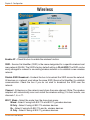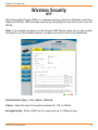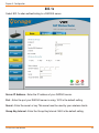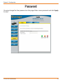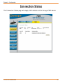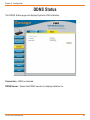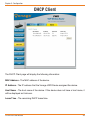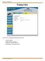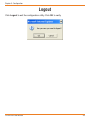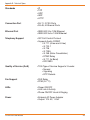
1
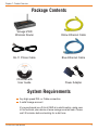
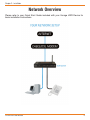
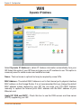
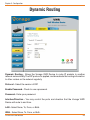
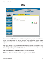
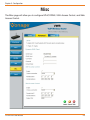
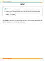
User Manual
Get Ready to Enjoy The New Way to Phone!
Welcome to Vonage!
It’s easy to get started with your Vonage VWR Device!
For assistance with installation or troubleshooting common problems, please refer to this
User Manual or Quick Start Guide.
Please visit www.vonage.com/vwr to obtain the most up-to-date User Manual and a
description of the latest VWR features.
Activation
If you purchased your Vonage VWR Device from a retail store, you must first activate
your Vonage phone service by visiting www.vonage.com/activate.
After activation, wait 30 minutes before checking for a dial tone.
You will need your MAC ID, which is located on your Vonage VWR Device. The MAC ID is
a combination of twelve letters and numbers. Be sure to enter all of the characters. After
you have chosen a plan and activated, please follow the step-by-step installation guide
to set up your equipment.
D-Link VWR User Manual
Table of Contents
Table of Contents
Welcome to Vonage!....................................................................................................... I
Chapter 1 - Product Overview...................................................................................... 1
Package Contents................................................................................................ 2
System Requirements.......................................................................................... 2
Front Panel........................................................................................................... 3
Rear Panel............................................................................................................ 3
Chapter 2 - Installation.................................................................................................. 4
Network Overview................................................................................................ 5
Chapter 3 - Configuration............................................................................................. 6
Login..................................................................................................................... 7
WAN..................................................................................................................... 8
Dynamic IP Address........................................................................................ 8
Static IP Address............................................................................................. 9
PPPoE........................................................................................................... 10
LAN..................................................................................................................... 11
DHCP................................................................................................................. 12
Wireless.............................................................................................................. 14
Wireless Security................................................................................................ 15
WEP.............................................................................................................. 15
802.1x............................................................................................................ 16
WPA/WPA2.................................................................................................... 17
Password............................................................................................................ 18
System................................................................................................................ 19
Virtual Server...................................................................................................... 20
Filters.................................................................................................................. 22
Custom IP Filters........................................................................................... 23
Performance....................................................................................................... 24
Routing............................................................................................................... 25
Dynamic Routing................................................................................................ 26
D-Link VWR User Manual
II
DMZ.................................................................................................................... 27
Misc.................................................................................................................... 28
UPnP............................................................................................................. 29
DDNS............................................................................................................ 30
SSH Access Control...................................................................................... 31
Web Access Control...................................................................................... 32
Network Statistics............................................................................................... 33
Connection Status.............................................................................................. 34
DDNS Status...................................................................................................... 35
DHCP Client....................................................................................................... 36
Product Info........................................................................................................ 37
Ping Test............................................................................................................. 38
Logout................................................................................................................. 39
Appendix A - Troubleshooting.................................................................................... 40
IVR Messages.................................................................................................... 43
Appendix B - Technical Specifications...................................................................... 44
D-Link VWR User Manual
III
Chapter 1 - Product Overview
Chapter 1 - Product Overview
Product Overview
D-Link VWR User Manual
1
Chapter 1 - Product Overview
Package Contents
Vonage VWR
Wireless Router
Yellow Ethernet Cable
RJ-11 Phone Cable
Blue Ethernet Cable
CD-ROM with
User Guide
Power Adapter
System Requirements
Any high speed DSL or Cable connection
A valid Vonage account
If you purchased your D-Link VWR at a retail location, make sure
to first activate your device at www.vonage.com/activate. Please
wait 30 minutes before checking for a dial tone.
D-Link VWR User Manual
Chapter 1 - Product Overview
Front Panel
Power
Internet
Wireless
Ethernet (1-4)
Phone (1-2)
When the power light
stops blinking and is a
solid green, this indicates
that your adapter has
started up properly. Note
that both the power light
and the phone light must
be solid in order to make
a phone call.
A solid light indicates
connection on the
Internet port. This
light blinks during
data transmission.
A solid light indicates
that the wireless
segment is ready.
This light blinks
during wireless data
transmission.
A solid light indicates
a connection to an
Ethernet-enabled
computer on ports
1-4. This light
blinks during data
transmission.
Solid light indicates
that the phone
line is ready for
Vonage Internet
telephone or FAX
calls. A slow blinking
light indicates that
voicemail is present.
When the line is in
use or ringing, the
light will blink rapidly.
Note: When the Vonage Device is downloading/upgrading firmware from Vonage,the lights will blink rapidly in unison.
Rear Panel
Phone (1 & 2)
Ethernet (1-4)
Internet
Reset
Plug your phone into
port #1 and if you’ve
signed up for a second
Vonage phone line, an
optional phone or FAX
machine into phone
port #2.
Connect to other
Ethernet devices such
as computers using
standard Ethernet
cables.
This port is the
connection for the
Ethernet cable to the
Cable or DSL modem.
Press the reset button
for at least 10 seconds
to reset the Vonage
VWR Device back to
the default settings.
D-Link VWR User Manual
Power
Plug in the
supplied power
adapter.
Chapter 1 - Product Overview
Installation
D-Link VWR User Manual
2
Chapter 2 - Installation
Network Overview
Please refer to your Quick Start Guide included with your Vonage VWR Device for
basic installation instructions.
D-Link VWR User Manual
Chapter 3 - Configuration
Chapter 3 - Configuration
Configuration
D-Link VWR User Manual
3
Chapter 3 - Configuration
Login
Open a web browser such as Internet Explorer and enter the IP address (e.g. 192.168.15.1)
of the Vonage VWR router.
Enter user for the username and your password (default password is user). Click the
Login button.
D-Link VWR User Manual
Chapter 3 - Configuration
WAN
Dynamic IP Address
Select Dynamic IP Address to obtain IP Address information automatically from your
ISP. Select this option if your ISP does not give you any IP numbers to use. This option is
commonly used for cable modem and satellite services.
Name - The host name is optional but may be required by some ISPs.
MAC Address - The default MAC Address is set to the Internet port’s physical interface
MAC address on the Vonage Router. It is not recommended that you change the default
MAC address unless required by your ISP. You can enter your PC’s MAC Address
manually to replace the Internet port’s MAC address with the MAC address of your
Ethernet card.
Apply ISP DNS and SNTP - Check this box to use the DNS servers and time server
(SNTP) supplied by your ISP.
D-Link VWR User Manual
Chapter 3 - Configuration
Static IP Address
If you want to statically assign an IP address, click Static IP Address.
Select Static IP Address if all the Internet port’s IP information is provided to you by your
ISP. You will need to enter in the IP address, subnet mask, gateway address, and DNS
address(es) provided to you by your ISP. Each IP address entered in the fields must be
in the appropriate IP form, which are four octets separated by a dot (x.x.x.x). The Vonage
VWR Device will not accept the IP address if it is not in this format.
IP Address - Enter the IP address assigned by your ISP.
Subnet Mask - Enter the Subnet Mask assigned by your ISP.
Default Gateway Address - Enter the Gateway assigned by your ISP.
DNS1/DNS2 - The DNS server information will be supplied by your ISP.
Apply ISP DNS and SNTP - Check this box to use the DNS servers and time server
(SNTP) supplied by your ISP.
D-Link VWR User Manual
Chapter 3 - Configuration
PPPoE
Select PPPoE (Point to Point Protocol over Ethernet) if your ISP uses a PPPoE connection.
Your ISP will provide you with a username and password. This option is typically used
for DSL services. Make sure to remove your PPPoE software from your computer. The
software is no longer needed and will not work through a router.
Username - Enter your PPPoE username.
Password - Enter your PPPoE password.
Keep Alive - The amount of time of inactivity before disconnecting your PPPoE session.
Enter a Keep Alive time (in minutes) to define a maximum period of time for which the
Internet connection is maintained during inactivity. If the connection is inactive for longer
than the defined time, then the connection will be dropped. Enter 0 to ensure that your
DSL connection is always active.
Authentication - Select the authentication type for your ISP (Auto, CHAP, or PAP).
MTU - Enter the MTU value. The default is 1492.
Enforce MTU - Check this box to force all TCP traffic to conform with PPP MTU by
changing TCP maximum segment size to PPP MTU. If it is disabled, you may have
issues accessing some Internet sites.
Apply ISP DNS and SNTP - Check this box to use the DNS servers and time server
(SNTP) supplied by your ISP.
D-Link VWR User Manual
10
Chapter 3 - Configuration
LAN
IP Address - Enter the IP address of the Vonage VWR Device. The default IP address is
192.168.15.1. If you statically assign the IP settings on your computer(s), this IP address
must be the default gateway address and a DNS server address on your computer(s).
Note: If you change the IP address, once you click Apply, you will need to enter the new
IP address in your browser to get back into the configuration utility.
Subnet Mask - Enter the Subnet Mask. The default subnet mask is 255.255.255.0.
HostName - Enter a host name (Optional).
Domain - Enter your network domain name (Optional).
D-Link VWR User Manual
11
Chapter 3 - Configuration
DHCP
DHCP stands for Dynamic Host Control Protocol. The Vonage VWR Device has a
built-in DHCP server. The DHCP Server will automatically assign an IP address to the
computers on the LAN/private network. Be sure to set your computers to be DHCP
clients by setting their TCP/IP settings to “Obtain an IP Address Automatically.” When you
turn your computers on, they will automatically load the proper TCP/IP settings provided
by the Vonage VWR Device. The DHCP Server will automatically allocate an unused
IP address from the IP address pool to the requesting computer. You must specify the
starting and ending address of the IP address pool.
D-Link VWR User Manual
12
Chapter 3 - Configuration
Enable DHCP Server - Click this to allow the Vonage VWR Device to assign your
computers the IP settings automatically.
Start IP - Enter the starting address for the DHCP server’s IP assignment.
End IP - Enter the ending IP address for the DHCP server’s IP assignment.
Note: If you statically (manually) assign IP addresses to your computers or
devices, make sure the IP addresses are outside of this range or you may have
an IP conflict.
Lease Time - The length of time for the IP address lease. Enter the Lease time in
seconds.
Enable DHCP Relay - Select this option to enable DHCP Relay. When DHCP relay is
enabled, the Vonage VWR Device is responsible for forwarding DHCP requests and
responses between network clients and a specified DHCP server.
Relay IP - Enter the IP address of the DHCP server that client DHCP requests will be
relayed to.
Server and Relay Off - When the DHCP server and relay functions are turned off, the
network administrator must statically configure the IP address, subnet mask and DNS
settings of every host on the network. The same IP address cannot be assigned to more
than one host, and the Vonage VWR Device must reside on the same subnet as the
other hosts.
LAN Clients - If you want a computer or device to always have the same IP address
assigned, you can create a DHCP reservation. The Vonage VWR Device will assign the
IP address only to that computer or device.
Note: This IP address must be within the DHCP IP Address Range.
Enter IP Address - Enter the IP address you want to reserve.
MAC Address - Enter the MAC address of the computer you want to assign the
IP address to.
Hostname - Enter a name of the computer.
If your computer is already listed, simply check the reserve box and click Apply.
D-Link VWR User Manual
13
Chapter 3 - Configuration
Wireless
Enable AP - Check this box to enable the wireless function.
SSID - Service Set Identifier (SSID) is the name designated for a specific wireless local
area network (WLAN). The SSID’s factory default setting is DLinkVWR. The SSID can be
easily changed to connect to an existing wireless network or to establish a new wireless
network.
Disable SSID Broadcast - Uncheck the box to broadcast the SSID across the network.
All devices on a network must share the same SSID (Service Set Identifier) to establish
communication. Check the box if you do not wish to broadcast the SSID over the
network.
Channel - All devices on the network must share the same channel. (Note: The wireless
adapters will automatically scan and match the wireless setting.) For best results, use
channels 1, 6, or 11.
802.11 Mode - Select the mode from the drop-down menu.
Mixed - Select if using both 802.11b and 802.11g wireless devices.
B Only - Select if using all 802.11b wireless devices.
B+ - Select if using both 802.11b and b+ wireless devices.
G Only - Select if using all 802.11g wireless devices.
D-Link VWR User Manual
14
Chapter 3 - Configuration
Wireless Security
WEP
Wired Equivalent Privacy (WEP) is a wireless security protocol for Wireless Local Area
Networks (WLAN). WEP provides security by encrypting the data that is sent over the
WLAN.
Note: If you enable encryption on the Vonage VWR Device make sure to also enable
encryption on all the wireless clients or wireless connection will not be established.
Authentication Type - Select Open or Shared.
Cipher - Select the level of encryption desired: 64, 128, or 256-bit.
Encryption Key - Enter a WEP key. You may enter up to 4 different keys.
D-Link VWR User Manual
15
Chapter 3 - Configuration
802.1x
Select 802.1x when authenticating to a RADIUS server.
Server IP Address - Enter the IP address of your RADIUS server.
Port - Enter the port your RADIUS server is using. 1812 is the default setting.
Secret - Enter the secret or key. This secret must be used by your wireless clients.
Group Key Interval - Enter the Group Key Interval. 3600 is the default setting.
D-Link VWR User Manual
16
Chapter 3 - Configuration
WPA/WPA2
Wi-Fi Protected Access (WPA) is a wireless security protocol for Wireless Local Area
Networks (WLAN). WPA and WPA2 provide inproved security over WEP through the
temporal key integrity protocol (TKIP) and Advanced Encryption Standard (AES).
Note: If you enable encryption on the Vonage VWR Device make sure to also enable
encryption on all the wireless clients or wireless connection will not be established.
Group Key Interval - Enter the Group Key Interval. 3600 is the default setting.
RADIUS Server - If you are using a RADIUS server for authentication, click the radio
button and enter the RADIUS server’s IP address, Port, and Secret (key).
Pre-Shared Key - To use a passphrase for authentication, click the radio button and then
enter the PSK String (WPA passphrase).
D-Link VWR User Manual
17
Chapter 3 - Configuration
Password
You may change the User password on this page. Enter a new password and click Apply
to save.
D-Link VWR User Manual
18
Chapter 3 - Configuration
System
Factory Reset - Click to reset the Vonage VWR Device back to the default settings.
Reboot - Click to reboot or restart the Vonage VWR Device.
Restart Access Point - Click to restart the wireless function.
D-Link VWR User Manual
19
Chapter 3 - Configuration
Virtual Server
The Vonage VWR Device can be configured as a virtual server so that remote users
accessing Web or FTP services via the public IP address can be automatically redirected
to local servers in the LAN (Local Area Network).
The Vonage VWR Device firewall feature filters out unrecognized packets to protect your
LAN network so all computers networked with the Vonage VWR Device are invisible to
the outside world. If you wish, you can make some of the LAN computers accessible from
the Internet by enabling Virtual Server. Depending on the requested service, the Vonage
VWR Device redirects the external service request to the appropriate server within the
LAN network.
The Vonage VWR Device is also capable of port-redirection meaning incoming traffic to
a particular port may be redirected to a different port on the server computer.
Each virtual service that is created will be listed at the bottom of the screen in the Virtual
Servers List. There are pre-defined virtual services already in the table. You may use
them by enabling them and assigning the server IP to use that particular virtual service.
D-Link VWR User Manual
20
Chapter 3 - Configuration
LAN IP - Select a computer on your network to apply the rules to from the drop-down
menu.
New IP - Click New IP if your computer is not in the drop-down menu.
Allow Incoming Ping - Check this box to allow the application to allow incoming ping.
Some games and chat programs require this option to be enabled.
Category - Select the type of program.
Available Rules - Select the built-in application and click Add.
Applied Rules - This will list the applications that are active to the LAN IP address you
have selected from the LAN IP list.
Delete - Highlight an application from the Applied Rules list and click Delete to remove
it.
View - Highlight an application and click View to review its settings.
D-Link VWR User Manual
21
Chapter 3 - Configuration
Filters
Use IP (Internet Protocol) filters to allow or deny computers access to the Internet based
on their IP address.
LAN IP Address - Select the IP address from the drop-down menu to apply the rule to.
Block All Traffic - Check to block all traffic to and from the selected IP address.
Block Outgoing Ping - Check to block outgoing ICMP traffic from the selected IP
address. This is useful if your host has a virus that attempts a Ping-of-Death Denial of
Service attack.
Custom IP Filters - Click to create your own filter rules (see next page).
D-Link VWR User Manual
22
Chapter 3 - Configuration
Custom IP Filters
Filter Name - Enter a name of your filter rule.
Enable - Check to enable the filter rule.
Source IP - Enter the LAN-side IP address.
Source Netmask - Enter the LAN-side subnet mask.
Destination IP - Enter the destination IP address (0.0.0.0 for all).
Destination Netmask - Enter the destination subnet mask (255.255.255.255 for all).
Port Start - Enter the starting port to block.
Port End - Enter the ending port to block.
Protocol - Select the protocol (TCP, UDP, TCP and UDP, ICMP, and ANY).
D-Link VWR User Manual
23
Chapter 3 - Configuration
Performance
Beacon Interval - Beacons are packets sent by an Access Point to synchronize a wireless
network. Specify a value. 100 is the default setting and is recommended.
RTS Threshold - This value should remain at its default setting of 2432. If inconsistent
data flow is a problem, only a minor modification should be made.
DTIM interval - (Delivery Traffic Indication Message) 3 is the default setting. A DTIM is a
countdown informing clients of the next window for listening to broadcast and multicast
messages.
Fragmentation - The fragmentation threshold, which is specified in bytes, determines
whether packets will be fragmented. Packets exceeding the 2346 byte setting will be
fragmented before transmission. 2346 is the default setting.
D-Link VWR User Manual
24
Chapter 3 - Configuration
Routing
Static Routing - Static routes can be added if you require specific routes within your
internal network.
New Destination IP - Enter the network IP.
Mask - Enter the network subnet mask.
Gateway - Enter the gateway IP address. This is the gateway or router WAN IP address
on the destination network.
Metric - The Metric is the number of hops to the destination network.
D-Link VWR User Manual
25
Chapter 3 - Configuration
Dynamic Routing
Dynamic Routing - Allows the Vonage VWR Device to route IP packets to another
network automatically. The RIP protocol is applied, and broadcasts the routing information
to other routers on the network regularly.
Protocol - Select the version of RIP.
Enable Password - Check to use a password.
Password - Enter your password.
Interface/Direction - You may control the ports and direction that the Vonage VWR
Device will route to and from.
LAN - Select None, To, From, or Both.
WAN - Select None, To, From, or Both.
D-Link VWR User Manual
26
Chapter 3 - Configuration
DMZ
If you have a client PC that cannot run Internet applications properly from behind the
Vonage VWR Device, then you can set the client up for unrestricted Internet access.
It allows a computer to be exposed to the Internet. This feature is useful for gaming
purposes.
Enter the IP address of the internal computer that will be the DMZ host. Adding a client
to the DMZ (Demilitarized Zone) may expose your local network to a variety of security
risks, so only use this option as a last resort.
DMZ - Select Enabled or Disabled. By default the DMZ is disabled.
IP Address - Enter the IP Address of the computer to be in the DMZ.
D-Link VWR User Manual
27
Chapter 3 - Configuration
Misc
The Misc page will allow you to configure UPnP, DDNS, SSH Access Control, and Web
Access Control.
D-Link VWR User Manual
28
Chapter 3 - Configuration
UPnP
Click Enable to use UPnP (Universal Plug and Play). UPnP provides compatibility with
networking equipment, software and peripherals.
D-Link VWR User Manual
29
Chapter 3 - Configuration
DDNS
Dynamic Domain Name System is a method of keeping a domain name linked to a
changing IP Address. This is a useful feature since many computers do not use a static
IP address.
To use the DDNS update client built into the Vonage VWR Device, select your DDNS
provider from the drop-down menu and then click Enabled.
Username - Enter the username for your DDNS account.
Password - Enter the password for your DDNS account.
Domain Name - Enter the domain or host name for your DDNS account.
D-Link VWR User Manual
30
Chapter 3 - Configuration
SSH Access Control
To configure the Vonage VWR Device from a remote computer using SSH, check Enable
and enter the following:
Choose Connection - Select WAN.
Remote Host IP - Enter the IP address of the remote computer. Enter 0.0.0.0 to allow
any remote computer to connect.
Remote Netmask - Enter the subnet mask of the remote computer. Enter 255.255.255.255
to allow any remote computer to connect.
D-Link VWR User Manual
31
Chapter 3 - Configuration
Web Access Control
To configure the Vonage VWR Device from a remote computer using a web browser,
check Enable and enter the following:
Choose Connection - Select WAN.
Remote Host IP - Enter the IP address of the remote computer. Enter 0.0.0.0 to allow
any remote computer to connect.
Remote Netmask - Enter the subnet mask of the remote computer. Enter 255.255.255.255
to allow any remote computer to connect.
Redirect Port - Enter the port number you would like to use.
D-Link VWR User Manual
32
Chapter 3 - Configuration
Network Statistics
The Network Statistics page will display traffic statistics of the Vonage VWR device.
D-Link VWR User Manual
33
Chapter 3 - Configuration
Connection Status
The Connection Status page will display traffic statistics of the Vonage VWR device.
D-Link VWR User Manual
34
Chapter 3 - Configuration
DDNS Status
The DDNS Status page will display Dynamic DNS statistics.
Connection - WAN is selected.
DDNS Server - Select the DDNS service to display statistics for.
D-Link VWR User Manual
35
Chapter 3 - Configuration
DHCP Client
The DHCP Client page will display the following information:
MAC Address - The MAC address of the device.
IP Address - The IP address that the Vonage VWR Device assigned the device.
Host Name - The host name of the device. If the device does not have a host name, it
will be displayed as Unknown.
Lease Time - The remaining DHCP lease time.
D-Link VWR User Manual
36
Chapter 3 - Configuration
Product Info
The Product Info page will display the following:
• Model Number
• Ethernet MAC Address
• Gateway - Software Version
• Bootloader - Firmware Version
D-Link VWR User Manual
37
Chapter 3 - Configuration
Ping Test
The Ping Test page will allow you to test your connection to computers.
Enter IP Address to Ping - Type in the IP address you want to ping.
Packet Size - Enter the size of the packet (32 is the default size).
Number of Echo Requests - Enter the number of requests (4 is default).
D-Link VWR User Manual
38
Chapter 3 - Configuration
Logout
Click Logout to exit the configuration utility. Click OK to verify.
D-Link VWR User Manual
39
Appendix A - Troubleshooting
Appendix A - Troubleshooting
Troubleshooting
D-Link VWR User Manual
A
40
Appendix A - Troubleshooting
If your Internet connection doesn’t work:
You can solve many installation issues by resetting all of your equipment:
1. First, power down in this order:
a. Computer (shut down properly, it is not necessary to disconnect power
to your computer)
b. Vonage Device (unplug power cord from back of device)
c. Router, if you have one (unplug power cord from back of device)
d. DSL or Cable Modem (unplug power cord from back of device)
NOTE: Leave the modem unplugged for at least 60 seconds. (The 60 seconds is to
ensure the modem doesn’t “remember” old information). Confirm that all cables are
snapped firmly into place.
2. Turn the devices on one at a time in this order:
a. DSL or Cable Modem - Wait for the lights to come back on before
continuing. This may take several minutes. Most modems have a light
that should be lit solid when start-up is complete. If necessary, refer to
the information that came with your modem.
b. Router, if you have one - Wait for the lights to come back on (consult
router manual for sequence) before continuing. Wait at least 30 seconds
after the lights have stopped blinking.
c. Vonage Device - Wait for the power and phone(s) lights to be a solid
green. (The Internet light will blink whenever there is activity.)
d. Computer
• For more troubleshooting tips, visit www.vonage.com/help.
At this point, you should have both a dial tone and Internet connectivity.
3. Try opening your web browser to view a web page. If you cannot view a web page,
check to see whether your Cable or DSL prover is having connection problems in
your area.
D-Link VWR User Manual
41
Appendix A - Troubleshooting
If your Internet connection works, but you don’t hear a dial tone or a voice
recording:
1. Be sure your phone is plugged in to the Green Phone Port 1 on the rear
panel of the Vonage Device, and that it is disconnected from the wall jack
that a traditional phone uses.
2. Reset all of your equipment, following the steps described on page 41. After
you reset all your equipment, pickup your telephone handset to listen again
for a dial tone.
If you hear a voice recording instructing you to connect your phone to the Green
Phone 1 Port:
1. Hang up your phone.
2. Confirm that the phone cord is firmly plugged into the Green Phone Port 1,
and listen again for a dial tone.
If you’re still having trouble, please call 1-866-243-4357
In Canada, call 1-877-272-0528
During the startup process you may notice that the Power light on the front of the VWR is
blinking. These blinks indicate that the VWR is booting up with Vonage service. You may
find the following blink sequences helpful to you:
1 blink (blink, pause, repeat)
2 blinks (2 blinks, pause, repeat)
3 blinks (3 blinks, pause, repeat)
4 blinks (4 blinks, pause, repeat)
Rapid Blinking
Solid
D-Link VWR User Manual
VWR is powering up
VWR is obtaining an IP address
VWR is obtaining configuration from Vonage
VWR is registering with Vonage
Downloading/upgrading firmware (do not power down)
Startup process is complete
42
Appendix A - Troubleshooting
IVR Messages
Your Vonage VWR Device comes equipped with some pre-programmed voice messages
to help troubleshoot issues with your device. The errors are listed below and will
automatically be played in the case there is an error when you lift the receiver of a phone
attached to your device.
The following IVR messages are played on the Vonage VWR Device:
1. “The Vonage device has no network connectivity.”
You will hear this message when your phone line is properly set up and ready for calls,
but your Internet connection is down. Check to see if you are able to access the Internet
from your computer that is connected to your router. If not, check with your Internet
Service Provider to determine if they are having connection issues in your area.
2. “The Vonage device has no network settings.”
You will hear this message when your phone line is properly set up, but there are insufficient
or incorrect network settings. If you have set a static IP address, verify that the Default
Gateway and the DNS server address is the IP address of your router. Network issues
may be resolved by resetting your equipment.
3. “The Vonage device cannot contact the Vonage network.”
You will hear this message when your phone line is properly set up but cannot connect to
the Vonage network. This may be due to a change to the network settings. For example
you may be experiencing firewall issues. Check if your network setup has changed since
you last connected to the Vonage network.
4. “This telephone line cannot register to the Vonage network.”
You will hear this message when your phone line is properly set up and can connect to
the Vonage network, but cannot register to Vonage. Please verify that your router in front
of the Vonage VWR Device is not blocking any incoming traffic. If SPI is enabled on the
router, disable it.
5. “Your phone maybe plugged into the incorrect phone port. Please try the other
port. If you believe that you are connected to the correct phone port, please log
into your web account to check the status of your service.”
You will hear this message when your telephone is connected into a phone port that is not
set up for Vonage service. If you are plugged into Port 2, try moving to Port 1. In addition,
you can check the status of your Vonage service by logging into your web account.
For more troubleshooting tips, visit www.vonage.com/help.
D-Link VWR User Manual
43
Appendix B - Technical Specifications
Appendix B - Technical Specifications
Technical Specs
D-Link VWR User Manual
B
44
Appendix B - Technical Specs
Standards
• IP
• TCP
• UDP
• ARP
• HTTP
Connection Port
• RJ-11, 2 FXS Ports
• RJ-45, 4 Ethernet Ports
Ethernet Port
• IEEE 802.3 for 10M Ethernet
• IEEE 802.3u for 100M Ethernet
Telephony Support
• SIP Call Control Protocol
• Supports Audio CODEC
• G.711 (A-law and U-law)
• G.723.1
• G.726
• G.729A
• G.168 (Echo Cancellation)
• DTMF Relay
• G.711 (In Band)
• RFC2833
Quality of Service (QoS) • TOS-Type of Service Supports 3 Levels:
• Normal
• Signaling
• RTP Packets
Fax Support
• FAX Relay
• PCM (G.711)
LEDs
• Power ON/OFF
• LAN Link & Activity
• Phone ON/OFF Hook & Ringing
Power
• External AC Power Adapter
• Output: 12V AC, 1.25A
D-Link VWR User Manual
45
Appendix B - Technical Specs
Temperature
• Operating:0°C to 40°C
• Storing: -10°C to 55°C
Humidity
• 5%-95% Non-Condensing
Certifications • EMC: FCC Class B, CE Class B,
CSA international, CB
Dimensions
• 90mm x 82.46mm x 31mm (WxDxH)
Warranty
• 1 Year Limited Warranty
Vonage USA
Manual Version 1.0
August 3, 2006
Copyright ©2006 D-Link Corporation/D-Link Systems, Inc. All rights reserved. D-Link and the D-Link
logo are registered trademarks of D-Link Corporation or its subsidiaries in the United States and other
countries. Other trademarks are the property of their respective owners.
D-Link VWR User Manual
46