1
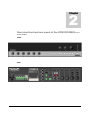
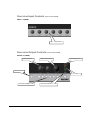
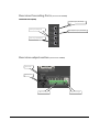
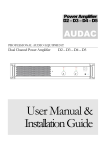
Public Address Amp COM12/COM24 AUDAC PROFESSIONAL AUDIO EQUIPMENT Public Address Amplifier COM12/COM24 User Manual & Installation Guide AUDAC PROFESSIONAL AUDIO EQUIPMENT User Manual & Installation Guide AUDAC http://www.audac.be [email protected] Index INTRODUCTION ........................................................................................................................................................................................................................... 3 ENVIRONMENT............................................................................................................................................................................................................................. 4 SAFETY REQUIREMENTS ......................................................................................................................................................................................................... 5 CAUTION – SERVICING............................................................................................................................................................................................................ 5 PIN CONNECTIONS ON CONNECTORS................................................................................................................................................................................ 6 OVERVIEW FRONT AND REAR PANEL OF THE COM12/COM24 (SAME FOR THE COM24) ............................................................................. 7 FRONT ........................................................................................................................................................................................................................................... 7 REAR ............................................................................................................................................................................................................................................. 7 OVERVIEW INPUT CONTROLS (SAME FOR THE COM24)............................................................................................................................................ 8 INPUT 1 - 6 (FRONT) ................................................................................................................................................................................................................... 8 OVERVIEW OUTPUT CONTROLS (SAME FOR THE COM24) ....................................................................................................................................... 8 OUTPUT 1-5 ( FRONT )............................................................................................................................................................................................................... 8 OVERVIEW INPUT SECTION LINE INPUTS (SAME FOR THE COM24)..................................................................................................................... 9 INPUT 1-6 (REAR) ....................................................................................................................................................................................................................... 9 OVERVIEW INPUT SECTION TELE-PAGING AND REMOTE MIC (SAME FOR THE COM24)........................................................................... 9 OVERVIEW CASCADING PORTS (SAME FOR THE COM24) ....................................................................................................................................... 10 CASCADING PORTS (REAR).................................................................................................................................................................................................. 10 OVERVIEW OUTPUT SECTION (SAME FOR THE COM24) .......................................................................................................................................... 10 GETTING STARTED................................................................................................................................................................................................................... 11 PRIORITY SETTINGS ................................................................................................................................................................................................................ 12 PHANTOM POWER .................................................................................................................................................................................................................... 12 TELEPHONE PAGING ............................................................................................................................................................................................................... 12 CONNECTING EXTERNAL EQUIPMENT ........................................................................................................................................................................... 13 CASCADING COM12/COM24 PUBLIC ADDRESS AMPLIFIERS .................................................................................................................................. 13 CONNECTING THE SPEAKERS ............................................................................................................................................................................................. 13 WIRE UP THE SYSTEM............................................................................................................................................................................................................. 14 ADDITIONAL INFORMATION COM12/COM24................................................................................................................................................................. 15 TECHNICAL SPECIFICATIONS ....................................................................................................................................................................................................... 15 PERSONAL NOTES ..................................................................................................................................................................................................................... 16 2 Introduction This section briefly describes the possibilities of the COM12/COM24 public address amplifier. T he COM12/COM24 public address amplifier was developed as an easy to use, flexible solution for multifunctional use. During the development of the COM12/COM24, the AUDAC-engineers wanted to achieve four goals: - Delivering a flexible audio solution to control multiple functions - Easy to use - Excellent sound quality - Modern and advanced design The COM12/COM24 has 2 stereo unbalanced line level inputs, 2 mono balanced line level inputs, 2 mono balanced line level inputs with priority settings and phantom power, 5 high impedance 100V mono output zones, 1 low impedance 4ohm mono output zone, a link input and output, an amp input and pre-amp output, a remote microphone input and the possibility to connect a telephone pager unit. The COM12/COM24 can be used in commercial applications such as restaurants, hotels, shops, warehouses, professional offices, public buildings, … A simple example: when installed in a shop, you could connect: a tuner to play your favorite radiostation, a microphone to make announcements, a telephone pager, … and off course the doorbell of the shop. 3 Chapter 1 Environment Do not place this unit in an enclosed environment such as a bookshelf or closet. Ensure that there is adequate ventilation to cool the unit. Do not block the ventilation openings. Do not place the unit in environments which contain high levels of dust, heat, moisture or vibration. Do not use the unit near water or other liquids. Make sure no water or other liquids can be spilled, dripped or splashed on the unit. This unit is developed for indoor use only. Do not use it outdoors. Do not place objects on top of the unit. Place the unit on a stable base. 4 Safety Requirements Always handle the unit with care. Only use a grounded socket outlet and a power cord with grounding plug to plug in the unit. This unit is not a toy. It should not be operated by children. Do not stick objects through the openings of the COM12/COM24. Do not open the unit (risk for electrical shock). The COM12/COM24 contains several ‹ jumpers › which can be set. These settings may only be done by qualified people. CAUTION – SERVICING This unit contains no user serviceable parts. Refer all servicing to qualified service personnel. Do not perform any servicing unless you are qualified to do so. Note This product conforms to the following European Standards: EN 50081-1: 1992, EN 50082-1: 1992, EN 60065: 1994 5 Pin connections on Connectors Cinch (RCA): tip = signal (left or right) ring = ground XLR: 1 = ground / shield 2 = +sig 3 = -sig XLR female: XLR male: 6.3mm (1/4”) balanced jack plug: tip = +sig ring = -sig sleeve = ground / shield 6.3mm (1/4”) unbalanced jack plug: tip = signal sleeve = ground / shield 6 Chapter 2 Overview front and rear panel of the COM12/COM24 (same for the COM24) FRONT REAR 7 Overview Input Controls (same for the COM24) INPUT 1 - 6 (FRONT) Input volume controls Overview Output Controls (same for the COM24) OUTPUT 1-5 ( FRONT ) 2 band tone control Master volume control Output clipping LED Chime button Output VU-bar Zone output routing buttons Power button and blue ON-led 8 Overview Input section line inputs (same for the COM24) INPUT 1-6 (REAR) RCA unbalanced line inputs Input Level Gain Controls Priority switch Microphone phantom power switch 6.3mm jack balanced line inputs XLR balanced line inputs XLR / 6.3mm jack balanced line inputs Overview input section tele-paging and remote mic (same for the COM24) Music on hold volume control Chime volume control Music on hold output Remote microphone volume control Telephone paging input Remote microphone input 9 Overview Cascading Ports (same for the COM24) CASCADING PORTS (REAR) Amplifier input (unbalanced) Link input (unbalanced) Pre-amplifier output (unbalanced) Link output (unbalanced) Overview output section (same for the COM24) Fuse holder Power cord 100V zone outputs 4ohm zone output 10 Chapter 3 Getting Started The COM12/COM24 public address amplifier can be switched on by pressing the power button on the front panel. The blue ‹ ON › led will light up if the device is powered-up. On the front panel you can route the input signals to a specific zone output simply by pressing the routing button of the zone output. If you want to route the input signals to all zone outputs, press the ‹ All › button. By pressing the routing buttons a second time, the routing will be undone. A preannounced chime can be played by pressing the ‹ Chime › button on the front panel. The volume of the input signals can be controlled by turning the volume knobs of the input signals on the front panel of the COM12/COM24. The master volume knob and the 2 band tone control let you adjust the volume, bass and treble of the output signal. A VU-bar indicates the signal level of the output signal. On the rear panel, the gain of the input channels and the remote microphone can be adjusted. The volume of the ‹ chime › and the ‹ music on hold › function can also be adjusted on the rear panel. The output section on the rear panel of the COM12/COM24 has 5 high impedance zone outputs for 100V lines and 1 low impedance zone output to connect a 4ohm speaker (or two 8 ohm speakers in parallel). 11 Priority settings The COM12/COM24 public address amplifier has a 3 layer priority mute function. The first layer has the highest priority, the third layer has the lowest priority. Layer 1 Telephone paging Layer 2 CH1, CH2, Chime, Remote Mic. Layer 3 CH3, CH4, CH5, CH6 When a source of a higher layer becomes active, all other input signals on the layers below are muted. The priority for CH1 and CH2 can be switched ‹ on › or ‹ off › on the rear panel. Phantom power When connecting a condenser microphone to CH1 or CH2, the phantom power for the microphone on the specific channel can be switched on at the rear panel. The phantom power supplies +15VDC to the microphone. Telephone paging Connect the tele-paging connector with the tele-paging output of your telephone paging unit. Connect the ‹ music on hold › connector to the ‹ music on hold › input of the telephone paging unit. The music for the ‹ music on hold › function is provided only by the music source connected to CH6. Set the ‹ music on hold › volume to a proper level. 12 Connecting external equipment If it is necessary to condition the output signal or to limit the output signal, an equalizer or limiter can be connected between the mixer section and the amplifier section of the COM12/COM24. This can be done by connecting the ‹ pre-amp output › to the equalizer or limiter input and connecting the equalizer or limiter output to the ‹ amp input ›. When you insert a 6.3mm plug into the ‹ amp input ›, the internal amplifier section will be disconnected from the internal mixer section. Cascading COM12/COM24 public address amplifiers When there’s need for more in- and outputs, the COM12/COM24 amplifiers can be cascaded by connecting the ‹ link output › from the master to the ‹ link input › of the slave. Connecting the speakers Speakers with a matching transformer can be connected to the 5 high impedance outputs on the rear panel. A 4ohm speaker (or two 8ohm speakers in parallel) can be connected to the 4ohm low impedance output at the rear ATTENTION: NEVER use the high impedance outputs and the low impedance outputs at the same time. Make sure the total combined load of the speakers does not exceed 120W (COM12)/240W (COM24). This is the maximum power the COM12/COM24 amplifier can give. 13 Wire up the System The COM12/COM24 amplifier is very easy to use. Following cable specs must be followed to guarantee a correct operation: 1. Speaker cable for amplified zone output 4ohm: minimum 2x1.5 mm2 (distance >15m: 2x2.5mm2) 2. Music sources and other line level inputs: must be connected with audio cable of good quality 14 Chapter 4 Additional Information COM12/COM24 Technical specifications COM12 Sensitivity Balanced Microphone Channels Balanced Line Channels Balanced Remote Microphone station Balanced Telephone Paging Unbalanced Link In Unbalanced Amp In -50dB±3dB -22dB±3dB -50dB±3dB -21dB±3dB -17dB±3dB -0dB±3dB Frequency Response (1Watt from speaker output tap. 100Hz-10kHz) THD+N by 1 kHz Signal to Noise ratio +1.5dB / -3dB Less than 0.5% 90 dB@1kHz Phantom Power +15V DC Zone outputs 1-5 Output level & impedance COM24 100V 100V – 42 ohm 70V – 21 ohm 25V – 2,6 ohm 4 ohm – 31V 100V – 83 ohm 70V – 42 ohm 25V – 5,2 ohm 4 ohm – 22V Power Supply Max. power consumption 235V AC, 50-60Hz 170W Weight Dimensions (W x H x D) Unit height 260W 9.76 kg 8,5 kg 420 mm x 88mm x 320mm 2HE 15 Personal notes 16