1
Cinema 11a
o o o o o o o o o o o o o o o o o o o o o o o o o o o o o o o o o o o o o o o o o o o o o o o o o o o o o o o o o o o o o o o o o o o o o o o o o o o o o o o o o o o
OWNER’S MANUAL
HD Surround Sound Processor
NOTE: Before installing your new component, please read this manual carefully
as it will inform you of the product specifications, proper installation and correct
operating procedures for your unit. Also included in this manual are guidelines
on how to service and care for your new Cary Audio Design product.
TABLE OF CONTENTS
Important Safety Instructions .......................................................... 3
Welcome
Thank You ............................................................................................
Product Features ...................................................................................
Unpacking and Installation .....................................................................
Format Descriptions ...............................................................................
6
7
8
8
Specifications
Audio Inputs / Audio Outputs ............................................................... 13
Analog Audio Section ........................................................................... 13
Digital Audio ......................................................................................... 14
Main Path ............................................................................................. 14
Zone 2 Paths......................................................................................... 15
Control ................................................................................................. 16
Power Requirements.............................................................................. 16
Controls & Displays
Front Panel .........................................................................................
Rear Panel ...........................................................................................
Remote Control ....................................................................................
Zone 2 Remote Control .........................................................................
17
19
21
23
Installation
Location .............................................................................................. 24
Getting Started..................................................................................... 24
Connecting a Multi Channel Power Amplifier .......................................... 25
Second Zone (Zone 2) ......................................................................... 26
Power Control Connections ................................................................... 26
Remote Control ................................................................................... 26
Power Connection ................................................................................. 26
Auto Sound Setup
How to Perform Auto Sound Setup.......................................................... 27
Speaker Check .................................................................................... 29
Set Distance ........................................................................................ 29
Set Balance ......................................................................................... 30
Set Room EQ ...................................................................................... 30
Set Crossover Points ............................................................................ 30
Set Speaker Phase ............................................................................... 30
Manual Sound Setup
Set Speaker Configuration. ..................................................................... 32
Set Distance.......................................................................................... 33
Set Balance........................................................................................... 34
Set Channel Levels Using the Test Tone Function .................................... 35
Set Crossover Points .............................................................................. 36
Set Acoustic Calibration Room EQ .......................................................... 37
Setup Menu
Set Speaker Phase................................................................................. 39
Input .................................................................................................... 40
Assigned Inputs..................................................................................... 40
Change Input Names ............................................................................. 41
Set Analog IN Configuration…………………………………………………………….42
Set Analog IN Level Settings .................................................................. 43
Set HDMI IN Audio .......................................................................... 45
Listening to the Radio ...................................................................... 45
Connection Chart ............................................................................ 47
Zone 2 ........................................................................................... 48
1
TABLE OF CONTENTS
Set Zone 2 Input ............................................................................. 48
Set Zone 2 Volume .......................................................................... 48
Advanced Settings ................................................................................ 49
Set Password ........................................................................................ 49
Master Volume…………………………………………………………………………………….50
HDMI Audio Out .................................................................................... 50
AV Sync Delay....................................................................................... 50
Bright ................................................................................................... 51
Edit Custom Name................................................................................. 51
Set Infrared Remote (IR) Controls .......................................................... 52
Set Triggers .......................................................................................... 53
Set Auto Input Seek .............................................................................. 54
Set Late Mode for Dolby Digital .............................................................. 54
Set Restore Default................................................................................ 54
Service and Care
Care and Cleaning ............................................................................... 56
Factory Service .................................................................................... 56
Non-Warranty Repairs .......................................................................... 56
United States Limited Warranty ........................................................... 57
2
IMPORTANT SAFETY INSTRUCTIONS
WARNING: To reduce the risk of fire or electric shock, do
not expose this appliance to rain or moisture. The lightning
flash with arrowhead symbol within an equilateral triangle is
intended to alert the user to the presence of un-insulated
dangerous voltage within the product’s enclosure that may
be of sufficient magnitude to constitute a risk of electric
shock to persons.
CAUTION: To reduce the risk of electric shock, do not remove the cover. There are no user serviceable parts inside.
Please refer to qualified personnel for service.
ALERT: The exclamation point within an equilateral triangle is intended to alert the user of the presence of important
operating and maintenance (servicing) instructions in the literature accompanying the component.
1.
READ ALL INSTRUCTIONS: All the safety and operating instructions of your Cary Audio equipment should be read
before power is applied to the equipment.
2.
RETAIN OWNER'S MANUAL: These safety and operating instructions should be retained for future reference.
3.
HEED WARNING: All warnings on the unit and in the operating instructions should be adhered to.
4.
FOLLOW INSTRUCTIONS: All operating and use instructions should be followed.
5.
CLEANING: Unplug the unit from the wall outlet before cleaning. The unit should be cleaned only as recommended
by the manufacturer.
6.
ATTACHMENTS: Do not use attachments not recommended by the unit manufacturer as they may cause hazards.
7.
WATER AND MOISTURE: Do not use the unit near water - for example, near a bath tub, wash bowl, kitchen sink,
or laundry tub; in a wet basement; or near a swimming pool.
8.
ACCESSORIES: Do not place the unit on an unstable cart, stand, tripod, bracket, or table. The unit may fall,
causing serious injury to a child, an adult, or damage to the unit. Mounting of the unit should follow the
manufacturer's instructions and should use a mounting accessory recommended by the manufacturer.
9.
VENTILATION: Slots and openings in the cabinet are provided for ventilation to ensure reliable operation of the
unit and to protect it from overheating. These openings must not be blocked or covered. The top or bottom panel
openings should never be blocked by placing the unit on a bed, sofa, rug, or other similar surface. The unit should
not be installed in a built-in location such as a bookcase or rack unless proper ventilation is provided. There should
be free space of at least 6 inches (16cm) above the unit and an opening behind the unit.
10. GROUNDING OR POLARIZATION: The unit may be equipped with a polarized alternating current line plug (a
plug having one blade wider than the other). This plug will fit into the power outlet only one way. This is a safety
feature. If you cannot insert the plug fully into the outlet, try reversing the plug. If the plug should fail to fit, contact
a licensed electrician to replace your obsolete outlet. Do not defeat the safety purpose of the polarized plug.
11. POWER SOURCES: The unit should be operated only from the type of power source indicated on the marking
label. If you are not sure of the type of power supplied to your home, consult your unit dealer or local power
company.
12. POWER CORD PROTECTION: Power supply cords should be routed so that they are unlikely to be walked on or
pinched by items placed on or against them. Pay close attention to cords where they enter a plug, or a convenience
receptacle, and the point where they exit from the unit.
13. OUTDOOR ANTENNA GROUNDING: If an outside antenna or cable system is connected to the unit, be sure the
antenna or cable system is grounded so as to provide protection against voltage surges and built-up static charges.
Article 810 of the National Electrical Code, NSI/NFPA 70, provides information regarding proper grounding of the
mast and supporting structure, grounding of the lead-in wire to an Antenna-discharge unit, size of grounding
conductors, location of antenna-discharge unit, connection to grounding electrodes, and requirements for the
grounding electrode.
3
IMPORTANT SAFETY INSTRUCTIONS
14. LIGHTNING: For added protection for the unit during a lightning storm, or when it is left unattended and unused
for long periods of time, unplug it from the wall outlet and disconnect the antenna or cable system. This will prevent
damage to the unit due to lightning and power line surges.
15. POWER LINES: An outside antenna system should not be located in the vicinity of overhead power lines or other
electric light or power circuits, or where it can fall into such power lines or circuits. When installing an outside
antenna system, take extreme care to keep from touching such power lines or circuits as contact with them might be
fatal.
16. OVERLOADING: Do not overload wall outlets, extension cords, or integral convenience receptacles as this can
result in a risk of fire or electric shock.
17. OBJECT AND LIQUID ENTRY: Never push objects of any kind into the unit through openings as they may touch
dangerous voltage points or short-out parts that could result in a fire or electric shock. Never spill liquid of any kind
on the unit.
18. SERVICING: Do not attempt to service the unit yourself as opening or removing covers may expose you to
dangerous voltage or other hazards. Refer all servicing to qualified service personnel.
19. REPLACEMENT PARTS: When replacement parts are required, be sure the service technician has used
replacement parts specified by the manufacturer or have the same characteristics as the original part. Unauthorized
substitutions may result in fire, electric shock or other hazards.
20. SAFETY CHECK: Upon completion of any service or repairs to the unit, ask the service technician to perform safety
checks to determine that the unit is in proper operating condition.
21. WALL OR CEILING MOUNTING: The unit should be mounted to a wall or ceiling only as recommended by the
manufacturer.
22. HEAT: The unit should be situated away from heat sources such as radiators, heat registers, stoves, or other units
(including amplifiers) that produce heat.
23. IMPORTANT SAFETY NOTE: Before connecting a new component to your audio or home theater system it is
always good practice to make certain that all components are turned off, and preferably unplugged from their AC
power source. Many modern electronics products feature automatic turn-on circuits that may be activated during an
installation, causing the potential for damage to electronic components and/or speakers. Such damage is not
covered by product warranties and Cary Audio specifically disclaims responsibility for any such damage.
Power Cord: The removable power cord that is shipped with the player is specifically designed to be used with this
product. Other AC cords may be used, so consult your dealer for advice on AC power cords and high quality wire in
your system.
AC Fuse: The fuse is located inside the chassis and is not user serviceable. If power does not
come on, contact your authorized service representative.
Wiring: Cables that run inside of walls should have the appropriate markings to indicate
compliance with, and listing by the UL, CSA or other standards required by the UL, CSA, NEC or your local building
code. Questions about cables inside of walls should be referred to a qualified custom installer, or a licensed
electrician or low-voltage contractor.
Do Not Open the Cabinet: There are no user serviceable components inside this product. Opening the cabinet
may present a shock hazard, and any modification to the product will void your warranty. If water or any metal
object, such as a paper clip, coin, or staple accidentally falls inside the unit, disconnect it from the AC power source
immediately and contact Cary Audio for further instructions.
24. RECORDING COPYRIGHT: Recording of copyrighted material for other than personal use is illegal without
permission of the copyright holder.
25. NOTE TO CATV SYSTEM INSTALLER: This reminder is provided to call the CATV system installer's attention to
article 820-40 of the NEC, ANSI/NFPA 70, which provides guidelines for proper grounding and, in particular, specifies
that the cable ground shall be connected to the grounding system of the building, as close to the point of cable entry
as practical.
4
IMPORTANT SAFETY INSTRUCTIONS
26. FCC INFORMATION FOR USER:
CAUTION: ANY changes or modifications not expressly approved by the party responsible
for compliance could void the user's authority to operate the equipment.
NOTE: This equipment has been tested and found to comply with the limits for a Class B digital device pursuant to
Part 15 of the FCC Rules.
These limits are designed to provide reasonable protection against harmful interference in a residential installation.
This equipment generates and can radiate radio frequency energy and, if not installed and used in accordance with
the instructions, may cause harmful interference to radio communications. However, there is no guarantee that
interference will not occur in a particular installation. If this equipment does cause harmful interference to radio or
television reception, which can be determined by turning the equipment off and on, the user is encouraged to try to
correct the interference by one or more of the following measures:
- Reorient or relocate the receiving antenna.
- Increase the separation between the equipment and receiver.
Connect the equipment into an outlet on a circuit different from where the receiver is connected.
27. OUTDOOR ANTENNA INSTALLATION/SAFE ANTENNA AND CABLE
CONNECTION: If an outside antenna or cable system is connected to
the equipment, be sure the antenna or cable system is grounded so as to
provide protection against built up static charges and voltage surges,
Section 810 of the national Electrical Code, ANSI/NFP A70 (in Canada,
part 1 of the Canadian Electrical Code) provides information with respect
to proper grounding of the mast and supporting structure, grounding of
the lead-in wire to an antenna discharge unit, size of grounding
conductors, location of antenna discharge unit, connection to grounding
electrodes and requirements for the grounding electrode.
Keep Antenna Clear of High Voltage Power Lines or Circuits
An outside antenna system should be located well away from power lines, electric light or power circuits and where
it will never come into contact with these power sources if it should happen to fall. When installing an outside
antenna, extreme care should be taken to avoid touching power lines, circuits or other power sources as this could
be fatal. Because of the hazards involved, antenna installation should be left to a professional.
5
WELCOME
THANK YOU
Congratulations on becoming a Cinema 11a owner!
We, at Cary Audio Design, would like to thank you for purchasing the new Cinema 11a HD
Surround Sound Processor. The Cinema 11a is the latest generation in our line of award-winning
surround sound processors.
The Cinema 11a is the ultimate in surround sound processors. Utilizing the Cirrus Logic CS49700
series chipset and HDMI v1.3 inputs, the Cinema 11a has the ability to properly decode and
playback both the raw bitstream and lossless linear PCM signals from the latest high resolution
formats, including Dolby True HD, Dolby Digital Plus, DTS-HD Master Audio, and DTS-HD High
Resolution Audio. The Cinema 11a has the ability to set separate Listener Profile speaker settings
for playback of Music and Movies. The Cinema 11a uses the absolute highest quality components
available within the audio circuit, resulting in extraordinary sound quality, which is a known
trademark of Cary Audio Design products. The Cinema 11a also contains an HD radio tuner for
the highest resolution signals from FM broadcasts.
The Cinema 11a was designed for ease of use whether in normal home surround sound systems
or in more complex custom installations. It has an independent 2nd zone so you can experience
surround sound in your main home theater room as well as 2nd zone stereo sound in a different
location. A separate 2nd zone remote handset comes standard with the Cinema 11a so full control
of the input source selection in each of the two zones is at your fingertips.
All Main zone audio output connectors have 24 bit/192 kHz D/A converters operating in dual
differential mode for excellent sound quality and high dynamic range. In addition, the Cinema
11a includes 7.1 channel XLR balanced audio outputs for the Main zone if you are using a power
amplifier equipped with balanced input connections.
The Cinema 11a was designed to remain viable in a future of rapidly emerging and changing
digital technologies. It has a rear panel RS-232 serial port connector that provides for home
automation serial control, and also allows us to provide flash memory upgrades.
We firmly believe in high performance products that offer incredible value for the money. With its
leading edge technology, exceptional sound performance and ease of use, the Cinema 11a is
without question, the highest performing surround sound processor available today.
Thank you for your continued support and enjoy your Music and Movies!
The Cary Audio Design Team
6
WELCOME
PRODUCT FEATURES
The Cinema 11a is designed as an “audio only” surround sound processor. With the addition of
the new Cirrus Logic CS49700 series chipset and HDMI v1.3, the new Cinema 11a has the ability
to properly decode and playback both the raw bitstream and lossless linear PCM signals from all
of the high resolution audio formats available today such as Dolby True HD, Dolby Digital Plus,
DTS HD High Resolution Audio, and DTS HD Master Audio. Being that the Cinema 11a is an
“audio only” surround processor, the HDMI inputs are simple pass-though, repeater inputs so
there is no video processing taking place within the unit.
In addition to the ability to properly decode and playback the high resolution audio formats, the
Cinema 11a is also equipped with Dolby Digital Surround EX, Dolby Pro Logic II, Dolby Pro Logic
IIx, dts 96/24, dts NEO:6, and dts-ES decoding.
With dual 32-bit audio digital signal processing (DSP) engines, the Cinema 11a offers
unparalleled processing power. These DSP engines perform custom processing such as an auto
sound setup system, CES 7.1 decoding, bass enhancement, dialog enhancement, bass
management, high-precision digital crossover, and room EQ. This processing is available at
sample rates up to 192 kHz, with 24-bit resolution to retain top performance from all input
sources and listening modes. A DSP engine is dedicated to decoding multi-channel compressed
audio sources.
10 channels of 24-bit/96 kHz A/D converters can be used to convert stereo analog audio input
and 7.1 analog audio input signals to digital signals, allowing the Cinema 11a to provide the
benefits of precise digital signal processing without sacrificing signal integrity. Alternatively,
stereo analog XLR and 7.1 analog signals can bypass the A/D conversion and internal processing
to remain in the analog domain straight to the output connectors.
The Cinema 11a offers:
• 2 HDMI v1.3 inputs and 1 HDMI v1.3 output
• 8 inputs; one balanced and seven single ended with RCA connectors; including S/PDIF
coaxial, S/PDIF optical, and analog pairs
• 7.1 channel analog audio input connections
• Analog bypass option for stereo and 7.1 channel analog audio input connectors
• 24-bit/192 kHz D/A converters for all Main Zone audio channels
• Automatic and manual calibration of speaker distances and output levels
• Dual 32-bit DSP engines
• CES 7.1 decoding
• Dolby True HD, Dolby Digital Plus, Dolby Digital Surround EX, Dolby Pro Logic IIx and
Dolby Pro Logic II decoding
• DTS HD Master Audio, DTS HD High Resolution Audio, dts 96/24, dts-NEO:6 and dts-EX
(discrete and matrix) decoding
• RS-232 connector for flash memory software upgrades and configuration tool downloads
• Optical digital audio output connector for Zone 2 (TOSLINK)
• 3 12 volt output connections with 1/8” mini plug connectors
• 2 IR input connections
• Full sized XLR microphone input connector
• 7.1 Balanced audio output connectors for Main Zone
• HD Radio Tuner in addition to AM/FM
7
WELCOME
UNPACKING AND INSTALLATION
This section describes the proper unpacking and installation procedures for your new component.
Unpacking
All Cary Audio Design shipping cartons have been specially designed to protect their contents and
special care has been taken to prevent damage under normal shipping conditions. Mishandling
should be evident upon inspection of the shipping container. If shipping damage is found after
visual inspection, take care not to destroy the evidence. If necessary, document the damage with
photographs and contact the transport carrier immediately.
Carefully remove your new component from its packing carton and examine it closely for signs of
shipping damage. We strongly recommend saving all original packing cartons to protect your
component from damage should you wish to store it or ship it at a later date.
In the Box
When unpacking your Cinema 11a processor, make sure the following accessories are included.
You should find the following items within the box:
•
•
•
•
Power Cable
(x2) Remote Controls (batteries already installed)
Owner’s Manual
Warranty Card
Warranty Card
If you are the original purchaser of this unit and you have purchased it within North America, you
should fill out the enclosed warranty registration card and return it to Cary Audio Design within
15 days of your purchase. Cary Audio Design also suggests that you keep your original packing
cartons in case you ever need to ship the unit when moving to a new home. Warranty
restrictions apply. Consult the warranty section of this manual for details. Please be certain to
keep a copy of the original sales receipt from your Authorized Cary Audio Design dealer to
validate the warranty if ever needed.
FORMAT DESCRIPTIONS
dts-HD
DTS-HD Master Audio is capable of delivering audio that is a bit-for-bit identical to the studio
master. DTS-HD Master Audio delivers audio at super high variable bit rates –24.5 mega-bits per
second (Mbps) on Blu-ray discs and 18.0 Mbps on HD-DVD – that are significantly higher than
standard DVDs. This bit stream is so “fast” and the transfer rate is so “high” that it can deliver
the Holy Grail of audio: 7.1 audio channels at 96k sampling frequency/24 bit depths that are
identical to the original. With DTS-HD Master Audio, you will be able to experience movies and
music, exactly as the artist intended: clear, pure and uncompromised.
Manufactured under license under U.S. Patent #’s: 5,451,942; 5,956,674; 5,974,380; 5,978,762;
6,226,616; 6,487,535 & other U.S. and worldwide patents issued & pending.
8
WELCOME
DTS is a registered trademark and the DTS logos, symbol, DTS-HD and DTS-HD Master Audio are
trademarks of DTS, Inc. © 1996-2007 DTS, Inc. All Rights Reserved.
dts-HD
DTS-HD High Resolution Audio can deliver up to 7.1 channels of sound that is virtually
indistinguishable from the original. DTS-HD High Resolution Audio delivers audio at high constant
bit rates superior to standard DVDs – 6.0 Mbps on Blu-ray discs and 3.0 Mbps on HD-DVD to
produce outstanding sound quality. It is capable of delivering up to 7.1 channels at 96k sampling
frequency/24 bit depth resolution. It allows content creators to deliver rich, high definition audio
on movies where disc space may not allow for DTS-HD Master Audio.
Manufactured under license under U.S. Patent #’s: 5,451,942; 5,956,674; 5,974,380; 5,978,762;
6,226,616; 6,487,535 & other U.S. and worldwide patents issued & pending. DTS is a registered
trademark and the DTS logos, Symbol, DTS-HD, DTS-HD High Resolution Audio and DTS-HD
High Res Audio are trademarks of DTS, Inc. © 1996-2007 DTS, Inc. All Rights Reserved.
DTS was introduced in 1994 to provide 5.1 Channels of discrete digital audio into home theater
systems. DTS brings you premium quality discrete multi-channel digital sound to both movies and
music. DTS is a multi-channel sound system designed to create full range digital sound
reproduction. The no compromise DTS digital process sets the standard of quality for cinema
sound by delivering an exact copy of the studio master recordings to neighborhood and home
theaters. Now, every moviegoer can hear the sound exactly as the moviemaker intended.
DTS can be enjoyed in the home for either movies or music on DVD'S, LD'S, and CD'S.
DTS and DTS Digital Surround are registered trademarks of Digital Theater Systems, Inc.
The advantages of discrete multi-channel systems over matrix are well known. But even in
homes equipped for discrete multi-channel, there remains a need for high-quality matrix
decoding. This is because of the large library of matrix surround motion pictures available on
disc, VHS Hi Fi tape, and analog Stereo television broadcasts. The typical matrix decoder of today
derives a center channel and a mono surround channel from two-channel matrix stereo material.
It is better than a simple matrix in that it includes steering logic to improve separation, but
because of its mono, band-limited surround it can be disappointing to users accustomed to
discrete multi-channel sound.
Neo:6 offers several important improvements: Neo:6 provides up to six full-band channels of
matrix decoding from stereo matrix material. Users with 6.1 and 5.1 systems will derive six and
five separate channels, respectively, corresponding to the standard home-theater speaker
layouts. Neo:6 technology allows various sound elements within a channel or channels to be
steered separately, and in a way which follows naturally from the original presentation.
9
WELCOME
Neo:6 offers a music mode to expand stereo or matrix recordings into the five or six channel
layout, in a way which does not diminish the subtlety and integrity of the original stereo
recording.
DTS, DTS-ES Extended Surround, and Neo:6 are registered trademarks of Digital Theater
Systems, Inc.
DTS-ES Extended Surround is a new multi-channel digital signal format developed by Digital
Theater Systems Inc. While offering high compatibility with the conventional DTS Digital
Surround format, DTS-ES Extended Surround greatly improves the 360-degree surround
impression and space expression thanks to further expanded surround signals. This format has
been used professionally in movie theaters since 1999. In addition to the 5.1 surround channels
(FL, FR, C, SL, SR and LFE), DTS-ES Extended Surround also offers the SB (Surround Back)
channel for surround playback with a total of 6.1 channels. DTS-ES Extended Surround includes
two signal formats with different surround signal recording methods, as DTS-ES Discrete 6.1 and
DTS-ES Matrix 6.1.
DTS, DTS-ES Extended Surround, and Neo:6 are registered trademarks of Digital Theater
Systems, Inc.
The stereo CD is a 16-bit medium with sampling at 44.1kHz. Professional audio has been 20- or
24-bit for some time, and there is increasing interest in higher sampling rates both for recording
and for delivery into the home. Greater bit depths provide extended dynamic range. Higher
sampling rates allow wider frequency response and the use of anti-alias and reconstruction filters
with more favorable aural characteristics. DTS 96/24 allows for 5.1channel sound tracks to be
encoded at a rate of 96kHz/24bits on DVD-Video titles. When DVD-video appeared, it became
possible to deliver 24-bit, 96 kHz audio into the home, but only in two channels, and with serious
limitations on picture. This capability has had little use. DVD-audio allows 96/24 in six channels,
but a new player is needed, and only analog outputs are provided, necessitating the use of the
D/A converters and the analog electronics provided in the player.
DTS 96/24 offers the following:
1. Sound quality transparent to the original 96/24 master.
2. Full backward compatibility with all existing decoders. (Existing decoders will output a 48
kHz signal)
3. No new player required: DTS 96/24 can be carried on DVD-video, or in the video zone of
DVD-audio, accessible to all DVD players.
4. 96/24 5.1 channel sound with full-quality full-motion video, for music programs and
motion picture soundtracks on DVD-video.
10
WELCOME
Dolby® TrueHD is Dolby’s next-generation lossless technology developed for high-definition discbased media. Dolby TrueHD delivers tantalizing sound that is bit-for-bit identical to the studio
master, unlocking the true high-definition entertainment experience on next-generation discs.
When coupled with high-definition video, Dolby TrueHD offers an unprecedented home theater
experience that lets you enjoy sound as stunning as the high-definition picture.
Manufactured under license from Dolby Laboratories. Dolby and the double-D symbol are
trademarks of Dolby Laboratories.
Dolby Digital Plus is a highly sophisticated and versatile audio coding based on Dolby Digital and
designed specifically to adapt to the changing demands of future audio, video delivery, and audio
storage systems while simultaneously retaining backwards compatibility with the existing Dolby
Digital 5.1-channel home theater systems in use today.
Manufactured under license from Dolby Laboratories. Dolby, Pro Logic, Surround EX, and the
double-D symbol are trademarks of Dolby Laboratories.
The Dolby Headphone technology provides a surround sound listening experience over
headphones.
When listening to multi-channel content such as DVD movies over headphones, the listening
experience is fundamentally different than listening to speakers. Since the headphone speaker
drivers are covering the pinna of the ear, the listening experience differs greatly from traditional
speaker playback. Dolby utilizes patented headphone perspective curves to solve this problem
and provides a non-fatiguing, immersive, home theater listening experience. Dolby Headphone
also delivers exceptional 3D audio from stereo material.
Manufactured under license from Dolby Laboratories. The double-D symbol is a trademark of
Dolby Laboratories.
Dolby Digital identifies the use of Dolby Digital audio coding for such consumer formats as DVD
and DTV. As with film sound, Dolby Digital can provide up to five full-range channels for left,
center, and right screen channels, independent left and right surround channels, and a sixth
(".1") channel for low-frequency effects.
Dolby Surround Pro Logic II is an improved matrix decoding technology that provides better
spatiality and directionality on Dolby Surround program material. It provides a convincing threedimensional sound field on conventional stereo music recordings. While conventional surround
programming is fully compatible with Dolby Surround Pro Logic II decoders, soundtracks will be
11
WELCOME
able to be encoded specifically to take full advantage of Pro Logic II playback, including separate
left and right surround channels. (Such material is also compatible with conventional Pro Logic
decoders.)
Dolby Digital EX creates six full-bandwidth output channels from 5.1-channel sources. This is
done using a matrix decoder that derives three surround channels from the two in the original
recording. For best results, Dolby Digital EX should be used with movies soundtracks recorded
with Dolby Digital Surround EX.
About Dolby Pro Logic IIx
Dolby Pro Logic IIx is fully compatible with Dolby Surround Pro Logic technology and can
optimally decode the thousands of commercially available Dolby Surround encoded video
cassettes and television programs with enhanced depth and spatiality. It can also process any
high-quality stereo or Advanced Resolution 5.1 channel music content into a seamless 6.1 or 7.1
channel listening experience.
Dolby Pro Logic IIx technology delivers a natural and immersing 7.1-channel listening experience
to the home theater environment. A product of Dolby's expertise in surround sound and matrix
decoding technologies, Dolby Pro Logic IIx is a complete surround sound solution that maximizes
the entertainment experience from stereo as well as 5.1 channel encoded sources.
Manufactured under license from Dolby Laboratories. Dolby, Pro Logic, and the double-D symbol
are trademarks of Dolby Laboratories.
*All trademarks belong to their original owners.
12
SPECIFICATIONS
The Cinema 11a is designed for long-term stability in virtually any home operating situation.
However, if the unit is operated outside the parameters outlined in this owner's manual, damage
may result. Please read this manual carefully before putting your new Cinema 11a processor into
operation.
The following section describes the Cinema 11a’s basic specifications. The specifications are
subject to change without notice or obligation.
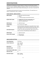
AUDIO INPUTS / AUDIO OUTPUTS
...........................................................................................................................................................................
Audio Inputs
7 - Stereo Pairs with RCA connectors
1 - XLR pair
1 - 7.1 channel analog input with RCA connectors
...........................................................................................................................................................................
Digital Audio Inputs
7 - Coaxial (RCA) for the seven single ended inputs
7 - TOSLINK for the seven single ended inputs
1 - XLR for the balanced input
...........................................................................................................................................................................
HDMI Inputs
2 – HDMI V1.3 inputs
...........................................................................................................................................................................
Sample Rates
44.1, 48, 88.2, 96 or 192kHz
...........................................................................................................................................................................
Accepts
16-24 bits PCM audio, DSD audio through HDMI, Dolby TrueHD,
Dolby Digital Plus, Dolby Digital Ex, dts-HD Master Audio, dts-HD
High Resolution Audio, dts and dts-ES discrete data formats
...........................................................................................................................................................................
Main Audio Outputs
7.1 RCA, L/R, Center, LFE (Subwoofer), Side L/R, Rear L/R 7.1
XLR, L/R, Center, LFE (Subwoofer), Side L/R, Rear L/R
...........................................................................................................................................................................
HDMI Output
1 – HDMI V1.3 output
...........................................................................................................................................................................
Zone 2 Audio Outputs
1 - RCA stereo pair
1 - TOSLINK digital
...........................................................................................................................................................................
ANALOG AUDIO SECTION
...........................................................................................................................................................................
Input Impedance
100 k Ohms
...........................................................................................................................................................................
Output Impedance
Main - RCA 330
Main - XLR 660
Zones 2 - 220
...........................................................................................................................................................................
Rated Input
2.0 Vrms
...........................................................................................................................................................................
Maximum Input
6.0 Vrms
...........................................................................................................................................................................
Rated Output (100 k load)
2.0 Vrms
...........................................................................................................................................................................
Minimum Load
5k
...........................................................................................................................................................................
Maximum Output
RCA - 8.0 Vrms
XLR - 16.0 Vrms
13
SPECIFICATIONS
...........................................................................................................................................................................
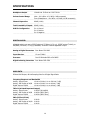
Headphone Output
100mW into 32 Ohms at 0.2% THD+N
...........................................................................................................................................................................
Volume Control Range
Main - -90.0 dB to +15.0 dB (1.0 dB increments)
Zone 2/Headphone - -90.0 dB to +15.0 dB (1.0 dB increments)
...........................................................................................................................................................................
Channel Separation
89 dB (1 kHz)
...........................................................................................................................................................................
Total Crosstalk b/t Inputs
89 dB (1 kHz)
...........................................................................................................................................................................
XLR Pin Configuration
Pin 1: Ground
Pin 2: Positive
Pin 3: Negative
...........................................................................................................................................................................
DIGITAL AUDIO
All digital audio inputs are to S/PDIF electrical (75 Ohms, 0.5 V p-p), S/PDIF optical (Toslink), or
AES/EBU (110 Ohms, 0.5 V p-p) standards, 44.1kHz to 192kHz regardless of input.
...........................................................................................................................................................................
Analog to Digital Converters
Burr-Brown PCM 1802
...........................................................................................................................................................................
Input Receiver
Cirrus CS 8416
...........................................................................................................................................................................
Processor
Dual 32 Bit Audio DSP at 516 MIPS
...........................................................................................................................................................................
Digital to Analog Converters
Burr-Brown DSD 1796
...........................................................................................................................................................................
MAIN PATH
RCA and XLR Output, 48 kHz Sampling Rate for all Digital Signal Paths
...........................................................................................................................................................................
Frequency Response and Bandwidth
Analog - Direct Inputs
10 Hz to 20 kHz, 1 Hz to 120 kHz (-3 dB)
Analog - DSP Inputs at 24/96 10 Hz to 20 kHz, 2 Hz to 44 kHz (-3 dB)
Digital Inputs at 24/96
10 Hz to 20 kHz, 1 Hz to 44 kHz (-3 dB)
...........................................................................................................................................................................
THD+N (at Rated Input and Output)
Analog - Direct Inputs
0.005% (90 kHz BW)
Analog - DSP Inputs at 24/96 0.003% (AES17 filter)
Digital Inputs at 24/96
0.003% (AES17 filter)
...........................................................................................................................................................................
IMD (CCIF at 15 kHz)
Analog - Direct Inputs
Analog - DSP Inputs at 24/48
Digital Inputs at 24/48
0.001%
0.001%
0.001%
...........................................................................................................................................................................
14
SPECIFICATIONS
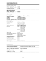
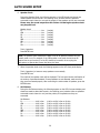
S/N Ratio (ref 2.0 Vrms)
Analog - Direct Inputs
Analog - DSP Inputs at 24/96
Digital Inputs at 24/96
108 dB
105 dB
107 dB
...........................................................................................................................................................................
IMD (CCIF at 15 kHz)
Analog - Direct Inputs
Analog - DSP Inputs at 24/48
Digital Inputs at 24/48
0.001%
0.001%
0.001%
...........................................................................................................................................................................
HDAM / AM Tuner
Frequency Range
Sensitivity (All Digital)
S/N Ratio
Distortion
One-Signal Selectivity (10kHz)
In 10kHz steps: 530kHz to 1,700kHz
-111dBm
50 dB typical, 43dB min
0.7% typical, 2.0% max
24 dB typical, 18dB min
...........................................................................................................................................................................
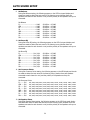
HDFM / FM Tuner
Frequency Range
Sensitivity
Signal-to-Noise Ratio
Distortion
Capture Ratio
Alternate Channel Selectivity
Stereo Separation
Frequency Response
Image Interference Ratio
IF Interference Ratio
AM Suppression Ratio
Spurious Interference Ratio
Antenna Input
87.9MHz to 107.9MHz
Hybrid mode -94dBm
All Digital -112dBm
Mono 80dB (at 65 dBf)
Stereo 76dB (at 85 dBf)
Mono 0.08% (100 Hz)
0.08% (1 kHz)
0.2% (6 kHz)
Stereo 0.2% (100 Hz)
0.15% (1 kHz)
0.3% (6 kHz)
1.0 dB
65 dB (400 kHz)
50 dB (1 kHz)
35 dB (30 Hz to 15 kHz)
30 Hz to 15 kHz
50 dB
80 dB
55 dB
70 dB
75 Ohms unbalanced
...........................................................................................................................................................................
ZONE 2 PATHS
...........................................................................................................................................................................
Frequency Response/Bandwidth
20 Hz to 20 kHz, 3 Hz to 140 kHz (+0, -3 dB)
...........................................................................................................................................................................
THD+N (at Rated Input and Output)
0.06% (90 kHz BW)
...........................................................................................................................................................................
IMD (CCIF at 15 kHz)
0.06%
...........................................................................................................................................................................
S/N Ratio (ref 2.0 Vrms)
97 dB
...........................................................................................................................................................................
15
SPECIFICATIONS
CONTROL
...........................................................................................................................................................................
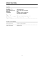
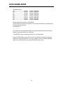
RS-232 Interface
Connection
Pinout (Statement DI side)
Baud Rate
Configuration
DB-9F, straight-wired
Pin 2: Tx, Pin 3: Rx, Pin 5: Ground
9600
8 data bits, 1 stop bit, no parity bits,
flow control (RTS, CTS, NONE)
...........................................................................................................................................................................
Trigger Outputs
Polarity
Maximum Current at 12 VDC
Sequential Delay
3.5 mm mono (tip positive), sleeve negative
150 mA (Triggers 1,2), 200 mA (Trigger 3)
100 ms
...........................................................................................................................................................................
POWER REQUIREMENTS
...........................................................................................................................................................................
Power Requirements
117VAC or 220VAC 50-60Hz
...........................................................................................................................................................................
Power Consumption
Maximum 50 W
...........................................................................................................................................................................
16
CONTROLS AND DISPLAYS
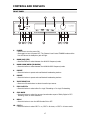
FRONT PANEL
1
15
13
14
12
11
<
SETUP
Cinema 11a
+
192kHz/24 bit D/A Converter
Surround Sound Processor
ENTER
<
POWER
AM/FM
HD RADIO
< PRESET >
1
2
3
4
5
6
2
3
8
HDMI 1
HDMI 2
7.1 IN
PRO
LOGIC IIx
MASTER VOLUME
SUR.
MODE
NEO:6
4
5
7
6
CES 7.1
MODE
INPUT
TUNER
1
7
8
9 10
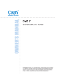
1.
POWER
• Press once to turn the power ON.
• Press again to turn the power OFF. The Cinema 11a will enter STANDBY mode and the
blue LED above the headphone jack will light.
2.
BAND (AM)/(FM)
• Press this button to select between the AM & FM frequency bands.
3.
BAND HDAM/HDFM (HD RADIO)
• Press this button to select between the HDAM & HDFM frequency bands.
4.
PRESET
• Press this button to preset and recall desired broadcasting stations.
5.
PRESET
• Press this button to preset and recall desired broadcasting stations.
6.
INPUT SELECTOR
• Press one of these buttons to select the audio input source.
7.
PRO LOGIC IIx
• Press this button to select either Pro Logic II decoding or Pro Logic IIx decoding
8.
SUR. MODE
• Press this button to select the surround sound mode as part of Dolby Digital or DTS
decoding; music or movie selections.
9.
NEO:6
• Press this button to turn the NEO:6 mode ON or OFF.
10. CES 7.1
• Press this button to select CES 7.1 on, CES 7.1 all stereo, or CES 7.1 all mono mode.
17
CONTROLS AND DISPLAYS
1
15
13
14
12
11
<
SETUP
Cinema 11a
+
192kHz/24 bit D/A Converter
Surround Sound Processor
ENTER
<
POWER
AM/FM
HD RADIO
< PRESET >
1
2
3
4
5
6
2
3
8
HDMI 1
HDMI 2
7.1 IN
PRO
LOGIC IIx
MASTER VOLUME
SUR.
MODE
NEO:6
4
5
7
6
CES 7.1
MODE
INPUT
TUNER
1
7
8
9 10
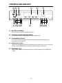
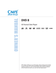
11. MASTER VOLUME KNOB
• Use this knob to adjust the overall volume level.
12. INFRARED RECEIVING SENSOR WINDOW
• This window receives infrared signals from the remote control.
13. ALPHANUMERIC DISPLAY
• This twenty-character display provides a wide range of information concerning the
operation of the Cinema 11a.
14. NAVIGATION / ENTER
• Use the four navigation buttons to move through menu options shown on the Cinema 11a
display. Use the ENTER button to confirm the selections made in the menus.
15. HEADPHONE JACK
• Use for Dolby Headphone playback of movies or personal listening to the AM/FM radio
section.
18
CONTROLS AND DISPLAYS
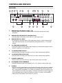
REAR PANEL
19
17
18
16
15
2
HDMI 1 INPUT
HDMI 2 INPUT
AUTO
SETUP
MIC- IN
ZONE 2
DIGITAL
OUT
AM LOOP
3
4
5
6
7
9
10
12 11
DIGITAL INPUT
1
ANTENNA
FM
75
13
14
1
1
2
IR INPUT ZONE
RS 232
8
8
2
3
TRIGGERS
AC POWER
[ ] 117V 50/60 Hz
[ ] 220V 50/60 Hz
7.1 PREAMPLIFIER OUTPUT
HDMI OUTPUT
1
2
3
4
5
6
7
8
FL
SL
CEN
SBL
FL
SL
CEN
SBL
FL
SL
FR
SR
CEN
SBL
LEFT
RIGHT
LEFT
FR
RIGHT
ANALOG AUDIO INPUT
1
SR
SW
ANALOG 7.1 INPUT
2
3
SBR
ZONE 2
AUDIO
OUT
4
FR
SR
SW
SBR
7.1 PREAMPLIFIER OUTPUT
5
CARY AUDIO DESIGN
SW
SBR
Cinema 11a Surround Sound Processor
6
7
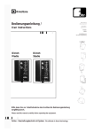
1.
ANALOG AUDIO IN (INPUT 1) XLR (L + R)
• Use these jacks for connection to balanced CD or DVD player analog audio output
connectors.
2.
ANALOG AUDIO IN (INPUTS 2 THROUGH 8) RCA
• Use these jacks for connection to CD, DVD, TV, or VCR input options.
3.
ANALOG AUDIO 7.1 INPUT
• By connecting a DVD audio player, SACD multi channel player, or other component that
has a multi-channel output, you can playback the analog audio with 5.1 or 7.1 channel
outputs.
4.
2ND ZONE ANALOG AUDIO OUT
• These jacks supply the analog stereo audio outputs to an external audio amplifier used to
power the speakers in the remote zone.
5.
7.1 PREAMPLIFIER OUTPUTS
• Use these jacks to connect to the main zone five or seven channel power amplifiers.
6.
7.1 PREAMPLIFIER OUTPUTS XLR
• Use these jacks to connect to the main zone five or seven channel power amplifiers.
7.
AC INLET CONNECTOR
• Plug the power cord into this AC inlet, then into the power outlet on the wall.
8.
DC TRIGGER OUTPUT TERMINALS
• Connect devices that need to be triggered by DC + 12V. (Screen, curtains, lights, etc.)
9.
IR INPUT
• Use the Z1 and Z2 remote jacks to connect external IR sensors. When the unit is installed
where it is not otherwise visible to the remote, connect an optional, external sensor and
the 1 (Main) jack will be activated. The Cinema 11a should be used for connections to the
power amplifiers for the main room speaker. The device connected to the zone trigger will
only be activated when the Multi-Zone system is turned on. Connect it to the amplifier
used to power the speakers in the second zone (Zone 2).
19
CONTROLS AND DISPLAYS
19
17
18
16
15
2
HDMI 1 INPUT
HDMI 2 INPUT
AUTO
SETUP
MIC- IN
ZONE 2
DIGITAL
OUT
AM LOOP
3
4
5
6
7
9
10
12 11
DIGITAL INPUT
1
ANTENNA
FM
75
13
14
1
2
1
IR INPUT ZONE
RS 232
8
8
2
3
TRIGGERS
AC POWER
[ ] 117V 50/60 Hz
[ ] 220V 50/60 Hz
7.1 PREAMPLIFIER OUTPUT
HDMI OUTPUT
1
2
3
4
5
6
7
8
FL
SL
CEN
SBL
FL
SL
CEN
SBL
FL
SL
FR
SR
CEN
SBL
LEFT
RIGHT
LEFT
FR
RIGHT
ANALOG AUDIO INPUT
1
SR
SW
ANALOG 7.1 INPUT
2
3
SBR
ZONE 2
AUDIO
OUT
4
FR
SR
SW
SBR
7.1 PREAMPLIFIER OUTPUT
CARY AUDIO DESIGN
5
SW
SBR
Cinema 11a Surround Sound Processor
6
7
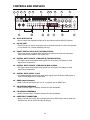
10. AUTO SETUP MIC-IN
• Use to connect the supplied microphone for Auto Setup and Auto Room EQ features.
11. RS-232 PORT
• The RS-232 port is used in conjunction with an external controller to control the operation
of the Cinema 11a. (custom installation use only)
12. ZONE 2 DIGITAL AUDIO OUT (TOSLINK OPTICAL)
• These jacks supply the digital audio outputs to an external surround sound processor
used to power the speakers in the remote zone.
13. DIGITAL INPUT (INPUTS 2 THROUGH 8) TOSLINK OPTICAL
• The digital inputs accept digital audio signals from CD players, DVD players or other
digital source components.
14. DIGITAL INPUT (INPUTS 2 THROUGH 8) RCA COAXIAL
• The digital inputs accept digital audio signals from CD players, DVD players or other
digital source components.
15. DIGITAL INPUT (INPUT 1) XLR
• This balanced digital input accepts digital audio signals from CD players, DVD players or
other balanced digital source components.
16. HDMI Output Connector
• Used to connect the Cinema 11a to a TV or projector with an HDMI input.
17. AM ANTENNA TERMINALS
• Used to connect indoor or outdoor antennas for radio broadcasts.
18. FM ANTENNA TERMINALS
• Used to connect indoor or outdoor antennas for radio broadcasts.
19. HDMI INPUT CONNECTORS
• Used to connect the Cinema 11a to components with an HDMI output such as cable and
satellite boxes, as well as DVD and Blu-ray players.
20
CONTROLS AND DISPLAYS
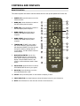
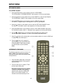
REMOTE CONTROL
This section explains how best to use the remote control to set up and operate the Cinema 11a.
1.
2.
POWER OFF: Press this button to turn the
Cinema 11a OFF.
BAND (FM): Press this button to switch to
the FM frequency band reception.
4.
BAND (HDAM): Press this button to
switch to the HDAM frequency band
reception.
5.
6.
7.
22
AM
3
FM
21
4
HDAM
20
5
HDFM
TUNER SCAN: If INPUT is set to AM or
FM, use this button to scan frequencies
that have been PRESET. The scan will cycle
through the stations, starting with the
current station, one after another with fivesecond delays.
8
ROOM EQ: Press this button to turn the
Room Equalization ON or OFF.
19
MEMORY
18
7
ENTER
17
AUTO SETUP
9
BRIGHT
EQ
LATE
16
SETUP
10
INPUT SELECTOR
7.1 IN
HDMI 1
HDMI 2
INPUT
SEEK
15
11
NAVIGATION/ENTER: Use the four
NAVIGATION buttons to move through
menu options shown on the Cinema 11a
display. Press the ENTER button in the
center to confirm selections made in these
menus.
9.
FM
MODE
TEXT
DISPLAY
TUNER
SCAN
BAND (HDFM): Press this button to
switch to the HDFM frequency band
reception.
AUTO SETUP: Press this button to start an
AUTO SOUND SETUP test on your system.
23
2
6
8.
TUNER SEEK
1
BAND (AM): Press this button to switch to
the AM frequency band reception.
3.
POWER
ON
POWER
OFF
12
MUTE
PLIIx
VOLUME
SUR.
MODE
NEO:96/24
CES 7.1
13
10. SETUP: Calls up the Setup Menu on the Cinema 11a display, if active.
11. INPUT SELECTOR: Use these buttons to select the desired source for your Cinema 11a.
12. MUTE: Press this button to mute the main volume of the Cinema 11a.
21
14
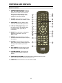
CONTROLS AND DISPLAYS
REMOTE CONTROL
13. SURROUND/DATA FORMAT: Press the
PLIIx, SUR. MODE, NEO:96/24, or CES 7.1
button once to select a surround format.
Press the same button again to cycle
through the various processing models
available for the selected format.
POWER
ON
POWER
OFF
TUNER SEEK
23
1
22
14. VOLUME: Press this button to adjust the
volume up and down from –90dB to +15dB.
15. INPUT SEEK: press this button to auto
select the next active audio input source.
2
AM
3
FM
21
4
HDAM
20
5
HDFM
FM
MODE
TEXT
DISPLAY
TUNER
SCAN
16. LATE (for Dolby Digital only): Cycles
through the various night dynamic range
compression modes. (Full, Half, No
compression)
MEMORY
18
6
7
ENTER
8
17. BRIGHT: Press this button to change the
brightness of the display. (Off, Low,
Medium, High)
17
AUTO SETUP
9
BRIGHT
EQ
LATE
16
SETUP
10
INPUT SELECTOR
7.1 IN
18. MEMORY: Press this button to store the
current broadcast band/reception frequency
into memory.
19
HDMI 1
HDMI 2
INPUT
SEEK
15
11
19. FM MODE: Press this button to select the
audio stereo mode or monaural mode when
listening to FM broadcast. (mono/auto
stereo)
12
MUTE
PLIIx
VOLUME
SUR.
MODE
NEO:96/24
13
20. TEXT DISPLAY: Press this button to start
TEXT Display on the HDFM & FM stations.
21. STATION PRESETS: These buttons are
used to preset the desired broadcasting
stations.
22. TUNER SEEK (UP/DOWN): Up: Performs tuning in ascending frequency order.
Down: Performs turning in descending frequency order.
23. POWER ON: Press this button to turn the Cinema 11a ON.
22
CES 7.1
14
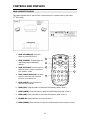
CONTROLS AND DISPLAYS
ZONE 2 REMOTE CONTROL
This section explains how to use the Zone 2 remote control in a remote room in your house.
(2nd Zone room)
1. ZONE 2 POWER OFF: Press this
button to power OFF Zone 2.
10
2. ZONE 2 PRESET: These buttons are
used recall preset broadcasting
stations.
2
3. ZONE 2 VOLUME: Press this button to
3
adjust the Zone 2 volume up and down
from -90dB to +15dB.
4. ZONE 2 INPUT SELECTOR: Use these
buttons to select the Zone 2 desired
source for your Cinema 11a.
O
ZONE 2 REMOTE
POWER
OFF
4
5. ZONE 2 MUTE: Press this button to
I
POWER
ON
AM
HD AM
6
1
8
HD FM
PRESET
FM
_
VOLUME
PRESET
+
7.1
IN
HDMI1
HDMI 2
MUTE
1
2
3
4
5
6
7
8
7
6
5
INPUT
mute the Zone 2 volume.
6. BAND (FM): Press this button to select the FM frequency band in Zone 2.
7. BAND (HDFM): Press this button to select the HDFM frequency band in Zone 2.
8. BAND (AM): Press this button to select the AM frequency band in Zone 2.
9.
POWER ON: Press this button to power ON Zone 2.
10. BAND (HDAM): Press this button to select the HDAM frequency band reception in Zone 2.
23
INSTALLATION
LOCATION
To assure proper operation and to avoid the potential for safety hazards, place the unit on a firm
and level surface capable of supporting its weight. When placing the unit on a shelf, be certain
that the shelf and any mounting hardware can support the weight of the unit and any additional
items in the equipment rack, or on the shelf.
When positioning the Cinema 11a, make certain that it has adequate ventilation on all sides, as
well as on the top and bottom. In particular, it is a good idea to provide at least two or three
inches of room above the unit for air circulation.
DO NOT place CDs, DVDs, videotapes, owner's manuals, or other paper or materials on top of
the unit, beneath the unit, or in-between multiple amplifiers in a stack. This will block airflow
causing heat build-up and may create a possible fire hazard.
If the unit is to be enclosed in a cabinet or rack, make certain there is adequate air circulation.
Sufficient ventilation should be provided so that hot air may exit, and cool air may enter the
cabinet. In some instances, a small cooling fan may be required to insure adequate airflow
through the cabinet. If you are in doubt about ventilation requirements for your specific
installation, Please contact us.
Avoid installation in humid locations, extremely hot or cold locations, or in areas that are exposed
to direct sunlight, moisture or space heating equipment.
GETTING STARTED
Before proceeding, please observe the following precautions when connecting devices to your
new Cinema 11a.
Do not plug the power cord into your Cinema 11a until all other connections have been made.
Always refer to the instructions that came with the component that you are connecting for
specific procedures, warnings and options.
For all analog connections, the red input jacks (R) are used for the right channel, and the white
input jacks (L) are used for the left channel. (RCA connectors)
Make sure to insert all plugs and connectors securely.
Improper connections can result in noise, poor performance, or damage to the equipment.
Do not bundle audio or video connection cables with power cords and speaker cables. Doing so
may adversely affect the picture and sound quality. For example; run all the power cords down
one side of the cabinet, all the signal cords down the other side, with the speaker wires down the
center.
When connecting devices to the digital inputs and outputs, you may also consider hooking up the
analog connections to and from the components to insure that all signals can be employed by the
preamp/processor and though Zone 2.
When using the TOSLINK optical input or output jacks, remove the protective cap and keep it in
a safe place. When these jacks are not in use the protective cap should be replaced.
24
INSTALLATION
When using a TOSLINK optical input or output jack, always use a high-quality optical fiber cable.
IMPORTANT: We strongly recommend that before you connect any loudspeakers to
your amplifiers, you complete all needed connections and set up procedures to your
Cinema 11a as outlined below. This will reduce the chance that a wrong connection or
other error will produce a high volume output that might damage your speakers or
other components.
Given the wide variety of components that can be connected to your Cinema 11a, there are
numerous ways in which your system can be assembled. To help you with this task, use the chart
at the end of this manual to record the components connected to your unit, as well as which type
of input (analog, coaxial, Toslink, etc) is used. Keep this chart for future reference.
There are many possible ways to connect a particular device. Use the diagrams on the following
pages as a guideline. The information in this section contains some of the more common
situations you might encounter in your system.
Always consult the owner's manuals that come with the components you are connecting to the
Cinema 11a for more information on the source component's connections.
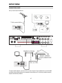
CONNECTING A MULTI CHANNEL POWER AMPLIFIER
Before attempting to plug any jacks into any power amplifier, verify that the power amplifier is
turned off and or disconnected from the AC mains. Failure to do so can potentially result in
severe damage to your amplifier or loudspeakers.
Use the audio jacks labeled OUTPUT from the Cinema 11a to an external power amplifier such as
the Cary Audio Design Model 7.125 Power Amplifier. The Cinema 11a can output up to 7.1
channels of sound depending on source components and source material.
The output jacks supplied by the Cinema 11a are: Left Front, Center, Right Front, Left Surround,
Right Surround, Left Surround Back, Right Surround Back, and Subwoofer. Be sure to verify that
the correct outputs are connected to the appropriate input jacks (Left Front to Left Front, Right
Surround Back to Right Surround Back, etc.)
When a powered subwoofer is used, connect the subwoofer output jack to the line input jack on
your subwoofer and follow any specific connection and or configuration, instructions supplied
with the subwoofer. If your subwoofer is a passive speaker, connect the subwoofer output jack
of the Cinema 11a to the input of the amplifier used to power the subwoofer, then connect the
subwoofer speaker itself to the subwoofer’s power amplifier.
SECOND ZONE (ZONE 2)
Use the L and R channel ZONE 2 AUDIO OUTPUT audio jacks to connect the Cinema 11a to the
audio inputs of an external amplifier or other audio component in a second zone. The signal
present will reflect the input selection of the Cinema 11a. The Zone 2 settings may be adjusted
within the Zone 2 setup menu. Zone 2 may be operated by the Zone 2 remote.
25
INSTALLATION
POWER CONTROL CONNECTIONS
The TRIGGER jacks are used to remotely turn-on other devices in your system when the Cinema
11a is powered ON. Power is applied to the MAIN trigger output jack when the Cinema 11a is
turned on from the Standby Mode.
We recommend that this jack be used to turn on a power amplifier such as the Cary Audio Model
7.125 or Model 7.250, but it may also be used to activate compatible products such as projection
screens, lights or blinds.
Connect a 3.5mm mono mini-plug between the Trigger 1 jack on the rear panel of the Cinema
11a and the low voltage trigger jack of the device to be controlled to enable remote turn-on of
that component. The Trigger 2 or 3 jack is activated when the Zone 2 Multi-room system is
turned on and should be used for control of amplifiers used to power the speakers installed in the
remote zone. It will remain activated as long as the Zone 2 Multi-room system is on, even when
the Cinema 11a is in the Standby mode for the main room.
REMOTE CONTROL
The IR INPUT jacks allow you to extend the on-board remote control sensor on the Cinema 11a
so that you may continue to control the Cinema 11a even when it is installed behind solid or
smoked cabinet doors or when the front panel sensor is otherwise not visible to the remote
control.
To extend the remote sensor of the Cinema 11a’s main zone, connect an optional remote sensor
to the IR INPUT 1 jack. The IR INPUT 2 jack is provided to enable remote control of the Cinema
11a's 2nd zone through the use of an optional remote sensor with Zone 2. Connect the sensor to
the IR INPUT 2 jack using a 3.5 mm mono mini-plug and the wiring specified by the sensor's
manufacturer. (many companies offer external IR receivers for this purpose)
POWER CONNECTION
Insert the supplied power cord into the AC input on the rear panel of the processor.
Cables make a difference: We suggest that different AC power cables and various RCA or XLR
patch cables can and do influence the possible sound of a system. Consult your dealer for advice
about using different cables in your system.
CAUTION: Before you plug the power cord into an AC wall outlet, ensure all
connections to the processor have been made correctly.
WARNING: Never disconnect the power cord from the Cinema 11a while the other
end is plugged into an AC outlet. Doing so may cause an electric shock. Always
connect the power by plugging into the AC outlet last and disconnect by unplugging
from the AC outlet first.
26
AUTO SOUND SETUP
The AUTO SOUND SETUP feature of the Cinema 11a will automatically measure the sound
characteristics of the main listening room where you have your home cinema system installed. It
has a seven-band auto sensing function that will try to optimize the sound quality and the overall
room frequency response for low bass, mid bass, mid range and high frequencies while you are
using it in the AUTO mode.
The room equalization (EQ) technology adopted by the Cinema 11a provides a superb listening
experience when it is utilized for music playback. We defeat the auto EQ function during movie
playback with Dolby Digital or DTS movie soundtracks. The room EQ function works for analog
signals converted to digital pulse code modulation (PCM) for surround sound listening or for PCM
signals from a CD or DVD player. This could be used as well for the AM/FM tuner signals if you
convert them to digital signals in the SETUP function by choosing DSP instead of bypass for the
Tuner. The measurement results are analyzed using an original algorithm and environmental
settings are made to improve the sound characteristics of the system in the listening area.
The room EQ can be used to average the overall room response by moving the microphone to as
many as six different physical locations in the room. For the averaging to take place you will need
to run the whole process again for each new placement of the microphone.
IMPORTANT NOTES:
The microphone is designed to be placed flat on a surface that is the same size or
smaller than the microphone base, with the mesh surface pointed UP at the ceiling.
The speakers should not have any obstruction between them and the microphone for
proper operation during auto set up. Setting this on a couch back is not a correct way
to do this. The microphone is designed to be pointed at the ceiling. It should not be
pointed at each speaker since this will make it read the room incorrectly.
The auto-setup feature and room EQ available within the Cinema 11a was
not designed by Cary Audio Design. We use the standard auto-setup and
room EQ feature that comes installed on the Cirrus Logic chipset used
within the Cinema 11a. We have found in our testing that the results
provided from this stock system may not always be accurate. In light of
this, we always recommend that you perform a manual setup using and SPL
meter and external test tones to get the most accurate settings possible for
your Cinema 11a within your specific room.
To set up the speaker system manually without using the AUTO SETUP feature, see the
MANUAL SETUP instructions in the next section. MANUAL SETUP is the factory
recommended procedure to obtain the most accurate results. AUTO SETUP may yield
superior results to using only your ears to balance the system. However, MANUAL SETUP will
yield even more precise set-up of the system if done properly with a sound pressure level meter
and a tape measure for measuring speaker distances and properly setting the level and distance
settings within the setup menu.
HOW TO PERFORM AUTO SOUND SETUP
During measurement, the VFD front panel display will show the current activity that is happening
within the Cinema 11a. The power amplifier needs to be turned on, naturally, for all of the
automatic settings to take place since the microphone is listening for the speakers so that it can
make the needed changes required by auto setup.
27
AUTO SOUND SETUP
1. Connect the supplied microphone to the Cinema 11a microphone input on the rear panel
of the Cinema 11a.
2. Place the microphone on a stand or small surface at the main listening location that does
not in any way obstruct the microphone’s ability to ‘listen’ to the room. Aim the
microphone straight up at the ceiling, not at the speakers.
STEPS:
• For the first (or only if you choose) auto set up measurement test, set the microphone
in the main listening position.
• Use a stand or tripod to position the microphone at ear level with a clear ‘view’ of all
of the speakers. Having a couch back between the microphone and the rear channel
speakers is not a clear view, for example.
• If you are using a powered subwoofer, set the input sensitivity control setting to about
1/3 or 1/2 of the volume gain setting. The output level needs to be in approximate
balance with the other inputs to the main speaker channels so the Cinema 11a can
make the balance between them. The subwoofer is the only channel in a normal
system that has an independent volume control on it, so if it is set at too high or too
low a setting, the Cinema 11a will not be able to balance the channels for subwoofer
(low bass) and the other channels properly. If you perform an auto setup run, and the
subwoofer is too loud or too soft in comparison to the other channels during setup,
adjust the sensitivity control on the subwoofer to make the needed change
(subwoofer volume up or down) for your system to balance properly with the auto
setup.
• During auto setup, it is important that you are not in the way of any of the speakers
and the microphone. Stand or sit outside of the main listening area, and run the
system with the remote control if possible, to avoid interference with the speakers
and the microphone. It is also important that no voices, music or TV noises should be
on in the room during setup, since this will interfere with the AUTO SETUP function
by giving the microphone other things to listen to besides the test tones it uses.
• WARNING: The set up noise is loud and should not be used at times when it might
disturb others. The test noise is similar to PINK NOISE with equal energy in all
audible octaves of sound.
3. Make sure the Cinema 11a is set to an input 1-8 where no source device is connected
before performing the auto-setup. DO NOT set the Cinema 11a to either HDMI 1 or
HDMI 2 as the auto-setup feature will not function if the unit is set to an HDMI input.
4. Press the AUTO SETUP button on the remote handset.
VFD will display:
Auto Sound Setup?
Press ENTER to start.
5. Press the ENTER button on the remote to start measurement.
VFD will display:
Connect Microphone?
Press ENTER to start.
28
AUTO SOUND SETUP
6. Speaker Check
During the Speaker Check, the following appears on the VFD display and checks are
made to detect the test sound in the listening room, whether there are speakers
connected to each channel or not and the polarity of the speakers as they are connected.
Please note; the sound output from the Cinema 11a during the speaker check
may be quite loud.
Speaker check
FL ......................................Yes
CEN ...................................Yes
FR......................................Yes
SR .....................................Yes
SBR....................................Yes
SBL ....................................Yes
SL ......................................Yes
SW.....................................Yes
(Yes/No)
(Yes/No)
(Yes/No)
(Yes/No)
(Yes/No)
(Yes/No)
(Yes/No)
(Yes/No)
Total: 8 speakers
Press ENTER now.
Note: The speaker check measures the state of use of all speakers whether they are
actually used or not. For example, if the CEN speaker is not used, the test tone will
require time to go from the FL to the FR; therefore, be careful not to unplug the
microphone or operate the Cinema 11a during this time.
7. When the speaker check ends, the following appears on the VFD front panel display:
Total: 8 speakers (or however many speakers are connected)
Press ENTER now
The results of the speaker check will be displayed. The front panel shows confirmation of
the number of speakers detected. If some speakers are not detected, make sure that
they are all connected properly. After confirming the total number of speakers, press the
ENTER button.
8. Set Distance
During the Set Distance testing, the following appears on the VFD front panel display and
checks are made to detect dart sound in the listening room (whether there are speakers
connected to each channel or not) and the polarity of the speakers as they are
connected.
Set Distance
FL .......................... 0.0ft
CEN ....................... 0.0ft
FR.......................... 0.0ft
SR ......................... 0.0ft
SBR........................ 0.0ft
SBL ........................ 0.0ft
SL .......................... 0.0ft
SW......................... 0.0ft
0.00m
0.00m
0.00m
0.00m
0.00m
0.00m
0.00m
0.00m
(0.0ft
(0.0ft
(0.0ft
(0.0ft
(0.0ft
(0.0ft
(0.0ft
(0.0ft
29
to
to
to
to
to
to
to
to
100ft/
100ft/
100ft/
100ft/
100ft/
100ft/
100ft/
100ft/
0.00m
0.00m
0.00m
0.00m
0.00m
0.00m
0.00m
0.00m
to
to
to
to
to
to
to
to
30.3m)
30.3m)
30.3m)
30.3m)
30.3m)
30.3m)
30.3m)
30.3m)
AUTO SOUND SETUP
9. Set Balance
During Set Balance testing, the following appears on the VFD front panel display and
checks are made to detect the test sound in the listening room (whether there are
speakers connected to each channel or not) and the polarity of the speakers as they are
connected.
Set Balance
FL .................................. 0.0dB
CEN ............................... 0.0dB
FR.................................. 0.0dB
SR ................................. 0.0dB
SBR................................ 0.0dB
SBL ................................ 0.0dB
SL .................................. 0.0dB
SW................................. 0.0dB
-15.0dB
-15.0dB
-15.0dB
-15.0dB
-15.0dB
-15.0dB
-15.0dB
-15.0dB
to
to
to
to
to
to
to
to
+
+
+
+
+
+
+
+
15.0dB
15.0dB
15.0dB
15.0dB
15.0dB
15.0dB
15.0dB
15.0dB
10. Set Room EQ
During Set Room EQ testing, the following appears on the VFD front panel display and
checks are made to detect the test sound in the listening room (whether there are
speakers connected to each channel or not) and the polarity of the speakers as they are
connected.
Set Room EQ
FL ............................. Set
CEN .......................... Set
FR............................. Set
SR ............................ Set
SBR........................... Set
SBL ........................... Set
SL ............................. Set
SW............................ Set
/
/
/
/
/
/
/
/
N/A
N/A
N/A
N/A
N/A
N/A
N/A
N/A
-15.0dB
-15.0dB
-15.0dB
-15.0dB
-15.0dB
-15.0dB
-15.0dB
-15.0dB
to
to
to
to
to
to
to
to
+ 15.0dB
+ 15.0dB
+ 15.0dB
+ 15.0dB
+ 15.0dB
+ 15.0dB
+ 15.0dB
+ 15.0dB
11. Set Crossover Points
During Set Crossover Points testing, the following appears on the VFD display and checks
are made to detect the test sound in the listening room (whether there are speakers
connected to each channel or not) and the polarity of the speakers as they are
connected.
Set Crossover Points
Full, 40Hz, 40Hz, 60Hz, 70Hz, 80Hz, 90Hz, 100Hz, 110Hz, 120Hz, 130Hz, 150Hz
FL ........ Full
CEN ..... Full
Full, 40Hz, 40Hz, 60Hz, 70Hz, 80Hz, 90Hz, 100Hz, 110Hz, 120Hz, 130Hz, 150Hz
Full, 40Hz, 40Hz, 60Hz, 70Hz, 80Hz, 90Hz, 100Hz, 110Hz, 120Hz, 130Hz, 150Hz
FR........ Full
Full, 40Hz, 40Hz, 60Hz, 70Hz, 80Hz, 90Hz, 100Hz, 110Hz, 120Hz, 130Hz, 150Hz
SR ....... Full
Full, 40Hz, 40Hz, 60Hz, 70Hz, 80Hz, 90Hz, 100Hz, 110Hz, 120Hz, 130Hz, 150Hz
SBR...... Full
Full, 40Hz, 40Hz, 60Hz, 70Hz, 80Hz, 90Hz, 100Hz, 110Hz, 120Hz, 130Hz, 150Hz
SBL ...... Full
Full, 40Hz, 40Hz, 60Hz, 70Hz, 80Hz, 90Hz, 100Hz, 110Hz, 120Hz, 130Hz, 150Hz
SL ........ Full
Full, 40Hz, 40Hz, 60Hz, 70Hz, 80Hz, 90Hz, 100Hz, 110Hz, 120Hz, 130Hz, 150Hz
SW....... Full
12. Set Speaker Phase
During Set Speaker Phase testing, the following appears on the VFD front panel display
and checks are made to detect the test sound in the listening room (whether there are
speakers connected to each channel or not) and the polarity of the speakers as they are
connected.
30
AUTO SOUND SETUP
Set Speaker Phase
FL ............................... Inphase
CEN ............................ Inphase
FR............................... Inphase
SR .............................. Inphase
SBR............................. Inphase
SBL ............................. Inphase
SL ............................... Inphase
SW.............................. Inphase
Inphase
Inphase
Inphase
Inphase
Inphase
Inphase
Inphase
Inphase
/
/
/
/
/
/
/
/
Outphase
Outphase
Outphase
Outphase
Outphase
Outphase
Outphase
Outphase
Storing Measurement Results in SETUP MENU
If the Cinema 11a senses that a speaker is out of phase, the VFD front panel display will
show the following sentence:
Out PHASE SPK
___ ___ ___
The Cinema 11a can automatically adjust the speakers listed as Out of Phase to being
properly in phase and will go to the next step.
- Press ENTER to store the settings and return to the “Setup Menu”.
Press the ENTER button on the remote to store all parameters including the equalizer
parameters in the “SETUP MENU”. If you do not want to store the resulting calculated
results in the “SETUP MENU”, press the AUTO SETUP button to exit.
31
MANUAL SOUND SETUP
SET SPEAKER CONFIGURATION
The first step in configuring the Cinema 11a to operate with your speaker system is to set the
type, number and crossover frequencies of your particular loudspeakers. You make these
selections using the SPEAKER SETUP menu shown below.
NOTE: The following selected menus appear on the Cinema 11a display:
SETUP MENU
LISTENING PROFILES
1. Press the SETUP button to enter the SETUP menu.
The “SETUP MENU / LISTENING PROFILES” menu appears on the front panel display.
2. Press the ENTER button on the remote to enter the “LISTENING PROFILES” setup menu.
The “LISTENING PROFILES / MOVIE MODE” appears on the front panel display.
3. Press the ENTER button on the remote to enter the “MOVIE MODE / Set Speaker Config”
settings menu.
The “MOVIE SPK Setting / Set Speaker Config” menu appears on the front panel display.
4. Press ENTER to enter the “Set Speaker Config” settings menu.
The “Set Speaker Config / FL .... Yes” menu appears on the front panel display.
5. Use the and buttons on the remote to adjust the FL (front left) speaker
configuration to either “Yes” or “No”.
6. Use the and buttons on the remote to cycle through the different speakers within
the system. The following options are available for each group of speakers:
• For FL (Front Left) you can select Yes or No. Select No when the speaker setup
does not include front L speaker. The Cinema 11a then redirects front L channel
signals to the center output connectors.
• For CEN (Center) you can select Yes or No. Select No when the speaker setup does
not include center speaker. The Cinema 11a then redirects center channel signals
to the front L/R output connectors.
• For FR (Front Right) you can select Yes or No. Select No when the speaker setup
does not include front R speaker. The Cinema 11a then redirects front R channel
signals to the center output connectors.
• For SR (Surround Right) you can select Yes or No. Select No when the speaker
setup does not include side R speaker. The Cinema 11a then redirects side R
channel signals to the front R output connectors.
• For SBR (Surround Back Right) you can select Yes or No. Select No when the
speaker setup does not include surround rear R speaker. The Cinema 11a then
redirects surround rear R channel signals to the side R output connectors.
• For SBL (Surround Back Left) you can select Yes or No. Select No when the
speaker setup does not include surround rear L speaker. The Cinema 11a then
redirects surround rear L channel signals to the side L output connectors.
• For SL (Surround Left) you can select Yes or No. Select No when the speaker setup
does not include side L speaker. The Cinema 11a then redirects side L channel
signals to the front L output connectors.
• For SW (Subwoofer) you can select Yes or No. Select No when the speaker setup
does not include SW speaker. The Cinema 11a then redirects SW channel signals
32
MANUAL SOUND SETUP
to the front L/R output connectors.
7. Press the button on the remote to select BACK within the menu then press ENTER to
return to the previous “SETUP MENU” to continue through the system setup process, or
simply press the SETUP button to exit to “SETUP MENU” completely.
SET DISTANCE
The DISTANCE SETUP is used to enter speaker distances (for proper sound delay).
Setting the Speaker Distance Delays
Setting the speaker delay is crucial to the proper performance of any surround decoder
component like the Cinema 11a. Your home theater system will not perform properly if this
process is not completed.
To accomplish this process, you will need a tape measure or other means of determining the
distance from each speaker to the primary listening position. Measure the distance from the main
listening point to each speaker. Front R, Side R, Surr BR, Surr BL, Side L and Subwoofer speaker.
Write the measured distances down before beginning the Distance Setup.
NOTE: The following selected menus appear on the Cinema 11a Display:
MOVIE SPK Setting
Set Distance
To set the speaker distance delays for your speakers:
1. Press the SETUP button to enter the SETUP MENU.
The “SETUP MENU / LISTENING PROFILES” menu appears on the front panel display.
2. Press the ENTER button on the remote to enter the “LISTENING PROFILES” setup menu.
The “LISTENING PROFILES / Movie Mode” menu appears on the front panel display.
3. Press the ENTER button on the remote to enter the “MOVIE MODE / Set Speaker Config”
settings menu.
The “MOVIE SPK Setting / Set Speaker Config” menu appears on the front panel display.
4. Press the button until you reach SET DISTANCE on the front panel display.
The “MOVIE SPK Setting / Set Distance” menu appears on the front panel display.
5. Press the ENTER button on the remote to enter the SET DISTANCE setup menu.
The “FL ……..0.0ft 0.0m” menu appears on the front panel display.
6. Use theand buttons on the remote to adjust the FL (front left) distance delays by
setting the measured distance.
7. To set the distance for each speaker within your system, you will need to measure, as
precisely as possible, the distances from your chosen listening/viewing position to the
various loudspeakers within your system.
Set the distance for the FL speaker to the nearest foot/meter. Rounding up is OK.
33
MANUAL SOUND SETUP
Distances can be set in the following increments:
- Feet 0 - 100 ft in 1 foot increments. Meters 0 to 30.3 meters in 0.3 meter increments.
- You can scroll in either direction using theand buttons on the remote.
8. Press the button on the remote when you have completed your distance selection for
the Front Left speaker. Repeat steps 5 and 6 for the Center, Front R, Side R, Surr BR,
Surr BL, Side L and Subwoofer speaker.
9. Press the button on the remote to select BACK within the menu then press ENTER to
return to the previous “SETUP MENU” to continue through the system setup process, or
simply press the SETUP button to exit the “SETUP MENU” completely.
SET BALANCE
This step adjusts the output level of each channel so that they are properly matched. This must
be done to ensure a correct presentation of multi-channel sound sources. The adjustment must
be as precise as possible, and it is almost impossible to accomplish by ear. Therefore, we
recommend you use a Sound Pressure Level meter. This device insures that all loudspeaker levels
are precisely matched and set accurately. (The Radio Shack analog Sound Pressure Level meter
is inexpensive and suitable for this task.)
NOTE: If for any reason you are not sure that you can accomplish this calibration task
or have any doubts as to how it should be done, please contact Cary Audio Design's
technical support group BEFORE attempting this process (919-355-0010), or use Auto
Setup.
On your analog SPL meter, set the meter to slow response, "C" weighting, and to the 70 dB
sensitivity scale. Position the meter at the approximate center of your listening position, at
average ear height [approximately 40-46 inches (102-117cm)] with its microphone positioned
vertically (pointing at the ceiling). Don't aim the microphone at the speakers, as this will produce
inaccurate results. To proceed with the adjustments, you will access the Channel Calibration
menu shown below. Set all channels to 75 dB level.
NOTE: The following selected menus appear on the Cinema 11a Display:
MOVIE SPK Setting
Set Balance
To set the channel levels for your system:
1. Press the SETUP button to enter the SETUP MENU.
The “SETUP MENU / LISTENING PROFILES” menu appears on the front panel display.
2. Press the ENTER button on the remote to enter the “LISTENING PROFILES” menu.
The “LISTENING PROFILES / MOVIE MODE” menu appears on the front panel display.
3. Press the ENTER button on the remote to enter the MOVIE MODE “Set Speaker Config”
settings menu.
The “MOVIE SPK Setting / Set Speaker Config” menu appears on the front panel display.
34
MANUAL SOUND SETUP
4. Press the button on the remote until you reach “SET BALANCE” on the front panel
display.
The “MOVIE SPK Setting / Set Balance” menu appears on the front panel display.
5. Press the ENTER button on the remote to enter the “SET BALANCE” menu.
The “SET BALANCE / TEST MODE.....Off” menu appears on the front panel display.
6. Press the button on the remote to select between manual or auto test tones, or to
turn the test tones off completely.
By selecting MANUAL, a special test tone will be generated as you move through each
speaker, allowing you to measure the output of the speaker that's playing.
7. Press the button on the remote until you reach FL (FRONT LEFT) on the front panel
display.
The “Set Balance / FL……0.0dB” menu appears on the front panel display.
8. Use the and buttons on the remote to adjust the speaker level.
You can adjust the selected channel level in 0.5dB steps across a range of -15dB to +
15dB. The recommended calibration level is 75dB/SPL as displayed on the meter.
9. Press the button on the remote when you have finished making the FRONT LEFT
level adjustment. Repeat steps 7 and 8 until you have completed setting the appropriate
level for each speaker within your system. Set all the levels to the 75dB reference level
on your meter.
10. When you have finished adjusting the levels for all of the speakers within your system,
press the button on the remote to select BACK, then press ENTER to return to the
previous “SETUP MENU” to continue through the system setup process, or simply press
the SETUP button to exit the “SETUP MENU” completely.
TO SET CHANNEL LEVELS USING THE AUTO TEST TONE FUNCTION
1. Press the SETUP button to enter the SETUP MENU.
The “SETUP MENU / LISTENING PROFILES” menu appears on the front panel display.
2. Press the ENTER button on the remote to enter the “LISTENING PROFILES” menu.
The “LISTENING PROFILES / MOVIE MODE” menu appears on the front panel display.
3. Press the ENTER button on the remote to enter the MOVIE MODE “Set Speaker Config”
settings menu.
The “MOVIE SPK Setting / Set Speaker Config” menu appears on the front panel display.
4. Press the button on the remote until you reach “SET BALANCE” on the front panel
display.
The “MOVIE SPK Setting / Set Balance” menu appears on the front panel display.
5. Press the ENTER button on the remote to enter the “SET BALANCE” menu.
The “SET BALANCE / TEST MODE.....Off” menu appears on the front panel display.
6. Select “AUTO” within the “TEST MODE” section of the “SET BALANCE” menu.
When you select this function, the Cinema 11a's test tone automatically cycles every few
35
MANUAL SOUND SETUP
seconds through all the speakers connected.
The unit cycles through the speakers in the following sequence:
FRONT LEFT > CENTER > FRONT RIGHT > SURROUND RIGHT > SURROUND BACK
RIGHT > SURROUND BACK LEFT > SURROUND LEFT > SUBWOOFER
7. Use the and buttons on the remote to adjust the speaker level.
You can adjust the selected channel level in 0.5dB steps across a range of -15dB to
+15dB. The unit will then resume cycling the Test Tone from speaker to speaker.
8. When you have finished adjusting the levels for all of the speakers within your system,
press the button on the remote to select BACK, then press ENTER to return to the
previous “SETUP MENU” to continue through the system setup process, or simply press
the SETUP button to exit the “SETUP MENU” completely.
SET CROSSOVER POINTS
The LPF/HPF (Low Pass Filter/High Pass Filter) Crossover menus are used to independently set
the internal High Pass filter of the Cinema 11a each of the speakers.
Setting the Speaker Crossover Points
In the Cinema 11a, the Crossover Points can be selected in 10Hz increments within a 40Hz to
150Hz range, or each speaker can be set to receive full range signal. Select the crossover point
closest to the low-frequency rating of the associated speaker. For instance, set to FRONT L/R
parameter to the crossover point closest to the low-frequency rating of the front speaker.
Select the subwoofer crossover point equal to the lowest crossover point of the other speakers.
In general, low frequencies will be redirected from the speakers with the highest crossover points
to the speakers with the lowest crossover points. Low-frequency signals lower than the lowest
crossover point will be redirected to the subwoofer.
NOTE: The following selected menus appear on the Cinema 11a Display:
MOVIE SPK Setting
Set Crossover Points
To set the crossover points for your speakers:
1. Press the SETUP button to enter the “SETUP MENU”.
The “SETUP MENU / LISTENING PROFILES” menu appears on the front panel display.
2. Press the ENTER button on the remote to enter the “LISTENING PROFILES” setup menu.
The “LISTENING PROFILES / MOVIE MODE” menu appears on the front panel display.
3. Press the ENTER button on the remote to enter the MOVIE MODE “Set Speaker Config”
settings menu.
The “MOVIE SPK Setting / Set Speaker Config” menu appears on the front panel display.
36
MANUAL SOUND SETUP
4. Press the button on the remote until you reach “SET CROSSOVER POINTS” on the
front panel display.
The “MOVIE SPK / Set Crossover Points” menu appears on the front panel display.
5. Use the and buttons on the remote to adjust the FL (Front Left) Crossover.
The crossover settings appear as follows as you scroll through them:
From 40 to 150 Hz in 10 Hz steps or FULL range.
6. Press the button on the remote when you have made a selection.
Repeat step 5 for the Center, Front R, Side R, Surr BR, Surr BL, Side L and Subwoofer
speaker.
7. When you have finished setting the crossover points for all of the speakers within your
system, press the button on the remote to select BACK, then press ENTER to return
to the previous “SETUP MENU” to continue through the system setup process, or simply
press the SETUP button to exit the “SETUP MENU” completely.
SET ACOUSTIC CALIBRATION ROOM EQ
Acoustic Calibration Equalization (EQ) is a kind of room equalizer for your speaker. It works by
measuring the acoustic characteristics of your room and neutralizing the ambient characteristics
that can color the original source material. This provides a 'flat' equalization setting. If you're not
satisfied with the automatic adjustment, you can also adjust these settings manually to get a
frequency balance that suits your tastes.
Setting the Acoustic Calibration Room EQ manually
If you have already completed automatically setting up your Cinema 11a using Auto Sound
SETUP press ENTER to restore to SETUP MENU. If you want to adjust your settings manually,
you can set the SET ROOM EQ manually following the directions below.
NOTE: The following selected menus appear on the Cinema 11a Display.
MOVIE SPK Setting
Set Room EQ
To set the Acoustic Calibration Room EQ manually:
1. Press the SETUP button on the remote to enter the SETUP MENU.
The “SETUP MENU / SPEAKER” menu appears on the front panel display.
2. Press the ENTER button on the remote to enter the “LISTENING PROFILES” setup menu.
The “LISTENING PROFILES / MOVIE MODE” menu appears on the front panel display.
3. Press the ENTER button to enter the MOVIE MODE “Set Speaker Config” settings menu.
The “MOVIE SPK Setting / Set Speaker Config” menu appears on the front panel display.
4. Press the button on the remote until you reach “SET ROOM EQ” on the front panel
display.
The “LISTENING PROFILES / Set Room EQ” menu appears on the front panel display.
5. Press the ENTER button on the remote to enter the “SET ROOM EQ” setup menu.
The “Set Room EQ / FL 80Hz…..0.0” menu appears on the front panel display.
37
MANUAL SOUND SETUP
6. Use the and buttons on the remote to adjust the FL (Front Left) 80Hz output
level. You can adjust the selected channel level in 0.5 dB steps across a range of -15dB
to +15dB.
7. Press the button on the remote when you have made a selection.
Repeat steps 5 for the 80Hz, 160Hz, 250Hz, 500Hz, 1KHz, 2KHz, 4KHz, 8KHz, 12KHz and
16KHz.
FL ........................80Hz
FL ...................... 160Hz
FL ...................... 250Hz
FL ...................... 500Hz
FL ........................1KHz
FL ........................2KHz
FL ........................4KHz
FL ........................8KHz
FL ......................12KHz
FL ......................16KHz
0/0dB
0/0dB
0/0dB
0/0dB
0/0dB
0/0dB
0/0dB
0/0dB
0/0dB
0/0dB
8. Press the button on the remote when you have made a selection.
Repeat steps 5 to 6 for the Center, Front R, Side R, Surr BR, Surr BL, Side L and
Subwoofer speaker.
9. When you have finished setting the Room EQ for all of the speakers within your system,
press the button on the remote to select BACK, then press ENTER to return to the
previous “SETUP MENU” to continue through the system setup process, or simply press
the SETUP button to exit the “SETUP MENU” completely.
38
SETUP MENU
SET SPEAKER PHASE
The Cinema 11a's SET SPEAKER PHASE feature uses phase correction measures to make sure
your sound source arrives at the listening position in phase, preventing unwanted distortion
and/or coloring of the sound.
SET SPEAKER PHASE technology provides coherent sound reproduction through the use of phase
matching for an optimal sound image at your listening position.
Setting the speaker phase manually
If you have already completed the Auto Sound SETUP, press ENTER to return to the SETUP
MENU. If you want to adjust your settings manually, you can use the SET SPEAKER PHASE menu
option, following the directions below.
NOTE: The following selected menus appear on the Cinema 11a Display.
MOVIE SPK Setting
Set Speaker Phase
To set the Speaker Phase manually:
1. Press the SETUP button on the remote to enter the “SETUP MENU”.
The “SETUP MENU / LISTENING PROFILES” menu appears on the front panel display.
2. Press the ENTER button on the remote to enter the “LISTENING PROFILES” setup menu.
The “LISTENING PROFILES / MOVIE MODE” menu appears on the front panel display.
3. Press the ENTER button on the remote to enter the MOVIE MODE “Set Speaker Config”
settings menu.
The “MOVIE SPK Setting / Set Speaker Config” menu appears on the front panel display.
4. Press the button on the remote until you reach “SET SPEAKER PHASE” on the front
panel display.
The “MOVIE SPK Setting / Set Speaker Phase” menu appears on the front panel display.
5. Press the ENTER button on the remote to enter the “SET SPEAKER PHASE” setup menu.
The “Set Speaker Phase / FL Speaker …..In/Out Phase” menu appears on the front panel
display.
6. Use the and buttons on the remote to adjust the phase.
You can adjust each channel’s speaker to be “IN” phase or “OUT” of phase.
7. When you have finished setting the phase for all of the speakers within your system,
press the button on the remote to select BACK, then press ENTER to return to the
previous “SETUP MENU” to continue through the system setup process, or simply press
the SETUP button to exit the “SETUP MENU” completely.
39
SETUP MENU
INPUT
This menu is for matching the output of connected audio devices and the input jacks of this
Surround Sound Processor.
-
Assigned Inputs
Change input names
Set Analog in config
Set Analog in level
Set HDMI in Audio
ASSIGNED INPUTS
Assign input sources to input Connectors. The following selected menus appear on the Cinema
11a display:
Assigned Inputs
Input 1 XLR Digital
To assign inputs:
1. Press the SETUP button on the remote to enter the “SETUP MENU”.
The “SETUP MENU / LISTENING PROFILES” appears.
2. Press the button on the remote until you reach “INPUTS” on the front panel display.
The “SETUP MENU / INPUTS” menu appears on the front panel display.
3. Press the ENTER button on the remote to enter the “INPUTS” setup menu.
The “INPUTS / Assigned Inputs” menu appears on the front panel display.
4. Press the ENTER button on the remote to enter the “Assigned Inputs” setup menu.
The “Assigned Inputs / Input 1 XLR Digital” menu appears on the front panel display.
5. Use the
andbuttons on the remote to select XLR Digital or XLR Analog.
6. Press the button on the remote when you have made a selection.
Repeat steps for Input 1, Input 2, Input 3, Input 4, Input 5, Input 6, Input 7 & Input 8.
Input
Input
Input
Input
Input
Input
Input
Input
1
2
3
4
5
6
7
8
XLR digital / XLR Analog
Toslink 2 / Coaxial 2 / Analog
Toslink 3 / Coaxial 3 / Analog
Toslink 4 / Coaxial 4 / Analog
Toslink 5 / Coaxial 5 / Analog
Toslink 6 / Coaxial 6 / Analog
Toslink 7 / Coaxial 7 / Analog
Toslink 8 / Coaxial 8 / Analog
2
3
4
5
6
7
8
8. When you have finished setting the assigned inputs for all of the inputs within your
system, press the button on the remote to select BACK, then press ENTER to return
to the previous “SETUP MENU” to continue through the system setup process, or simply
press the SETUP button to exit the “SETUP MENU” completely.
40
SETUP MENU
CHANGE INPUT NAMES
You can customize the name of the selected input. Custom Input Names can include up to twelve
characters. For example: DVD 7 or DVD 8 for Input 2.
NOTE: The following selected menus appear on the Cinema 11a Display.
SETUP MENU
INPUTS
To change input names:
1. Press the SETUP button on the remote to enter the “SETUP MENU”.
The “SETUP MENU / LISTENING PROFILES” menu appears on the front panel.
2. Press the button on the remote until you reach “INPUTS” on the front panel display.
The “SETUP MENU / INPUT” menu appears on the front panel display.
3. Press the ENTER button on the remote to enter the “INPUTS” setup menu.
The “INPUTS / Assigned Inputs” menu appears on the front panel display.
4. Press the button on the remote until you reach the “CHANGE INPUT NAMES” setup
menu.
The “INPUTS / Change Input Names” menu appears on the front panel display.
5. Press the ENTER button on the remote to enter the ”CHANGE INPUT NAMES” setup
menu.
The “Change Input Names / 71. In 7.1CH In” menu appears on the front panel display.
6. Press the ENTER button on the remote to enter the “7.1 IN” menu if you wish to rename
this input. The cursor automatically appears beneath the first character in the current
input name.
7. Use the and buttons on the remote to scroll through the different characters
above the cursor. The following characters are available to choose from:
0 123456789: ;<=>?@ABCDEFGHIJKLMNOPQRSTUVWXYZ
[\]-_\ abcdefghijklmnopqrstuvwxyz{|}-_
8. Once you have the character you would like on the screen in the space above the cursor,
use the button on the remote to advance to the next character space. The cursor will
automatically wrap to the first character space when the last (twelve) character space is
passed.
9. Use the
button on the remote to return to the previous character space.
41
SETUP MENU
10. Press the ENTER button on the remote to store the custom input name you have
selected.
11. Press the
7.1 In
INPUT
INPUT
INPUT
INPUT
INPUT
INPUT
INPUT
INPUT
BACK
1
2
3
4
5
6
7
8
button to select other input names.
7.1 CH IN
INPUT 1
INPUT 2
INPUT 3
INPUT 4
INPUT 5
INPUT 6
INPUT 7
INPUT 8
12. When you have finished changing the input names for all of the inputs within your
system, press the button on the remote to select BACK, then press ENTER to return
to the previous “SETUP MENU” to continue through the system setup process, or simply
press the SETUP button to exit the “SETUP MENU” completely.
SET ANALOG IN CONFIGURATION
The Cinema 11a allows analog sources to select bypass mode or DSP mode. When you select the
BYPASS mode, the Cinema 11a passes analog input signals directly to the main audio output
connectors. When you select DSP mode, the Cinema 11a sends analog input signals through A/D
conversion and internal processing before passing them to the main audio output connectors.
This allows analog sources to use bass management, speaker crossovers, speaker distance
calibration, and Room EQ.
To set Analog IN Configuration:
1. Press the SETUP button on the remote to enter the “SETUP MENU”.
The “SETUP MENU / LISTENING PROFILES” menu appears on the front panel display.
2. Press the button on the remote until you reach “INPUTS” on the front panel display.
The “SETUP MENU / INPUT” menu appears on the front panel display.
3. Press the ENTER button on the remote to enter the “INPUTS” setup menu.
The “INPUTS / Assigned Inputs” menu appears on the front panel display.
4. Press the button on the remote until you reach the “SET ANALOG IN CONFIG” menu.
The “INPUTS / Set Analog In Config” menu appears on the front panel display.
5. Press the ENTER button on the remote to enter the “SET ANALOG IN CONFIG” menu.
The “Set Analog In Config / INPUT 1…….Bypass” menu appears on the front panel diaply.
42
SETUP MENU
6. Use the and buttons on the remote to select the mode. You can select the
“BYPASS” mode or “DSP” mode. Please note that if a particular input has been set
to digital coax or digital toslink, “NOT AVAILABLE” will appear for this input as
you cannot set the analog configuration of an input set to digital.
7. Press the button on the remote when you have made a selection to move to the next
input. Repeat steps 6 and 7 for INPUT 2, INPUT 3, INPUT 4, INPUT 5, INPUT 6, INPUT 7,
INPUT 8, 7.1 INPUT and TUNER.
8. When you have finished setting the analog in configuration for all of the analog inputs
within your system, press the button on the remote to select BACK, then press
ENTER to return to the previous “SETUP MENU” to continue through the system setup
process, or simply press the SETUP button to exit the “SETUP MENU” completely.
NOTE: As you can see from these settings, it is possible to use the Cinema 11a as an
analog stereo preamp and as a surround sound preamplifier at the same time.
SET ANALOG IN LEVEL SETTINGS
This adjustment can be used to adjust 2-channel analog audio input levels for a selected input.
Despite attempts at standardization, analog sources still have a wide range of input levels. To
compensate for this, the Cinema 11a allows independent input level adjustment for each of the
stereo analog audio input connectors when the particular input is set to analog. Input level
adjustment is not available for the 7.1 channel analog audio input connector.
NOTE: The following selected menus appear on the Cinema 11a Display.
SETUP MENU
INPUTS
To set Analog IN Level:
1. Press the SETUP button on the remote to enter the “SETUP MENU”.
The “SETUP MENU / LISTENING PROFILES” menu appears on the front panel display.
2. Press the button on the remote until you reach “INPUTS” on the front panel display.
The “SETUP MENU / INPUTS” menu appears on the front panel display.
3. Press the ENTER button on the remote to enter the “INPUTS” setup menu.
The “INPUTS / Assigned Inputs” menu appears on the front panel display.
4. Press the button on the remote until you reach the “SET ANALOG IN LEVEL” menu.
The “INPUTS / Set Analog In Level” menu appears on the front panel display.
5. Press the ENTER button on the remote to enter the “LEVEL ADJUSTMENT” menu.
The “Set Analog In Level / Input 1” menu appears on the front panel display.
43
SETUP MENU
6. Use the and buttons on the remote to adjust the level of the INPUT 1. You can
adjust the selected channel level in 1.0 dB steps across a range of -18dB to +12dB.
Please note that if a particular input has been set to digital coax or digital
toslink, “NOT AVAILABLE” will appear for this input as you cannot set the
analog in level of an input set to digital.
7. Press the button on the remote when you have made a selection.
Repeat steps 6 and 7 for INPUT 2, INPUT 3, INPUT 4, INPUT 5, INPUT 6, INPUT 7 and
INPUT 8.
8. When you have finished setting the analog input level for all of the analog inputs within
your system, press the button on the remote to select BACK, then press ENTER to
return to the previous “SETUP MENU” to continue through the system setup process, or
simply press the SETUP button to exit the “SETUP MENU” completely.
44
SETUP MENU
SET HDMI IN AUDIO:
To set HDMI IN audio:
1. Press the SETUP button on the remote to enter the “SETUP MENU”.
The “SETUP MENU / LISTENING PROFILES” menu appears on the front panel display.
2. Press the button on the remote unit you reach “INPUTS” on the front panel display.
The “SETUP MENU / INPUTS” menu appears on the front panel display.
3. Press the ENTER button on the remote to enter the “INPUTS” setup menu.
The “INPUTS / Assigned Inputs” menu appears on the front panel display.
4. Press the button on the remote until you reach the “SET HDMI IN AUDIO” menu.
The “INPUTS / Set HDMI in audio” menu appears on the front panel display.
5. Press the ENTER button on the remote to enter the “SET HDMI IN AUDIO” setup menu.
The “Set HDMI in audio / HDMI 1…..Bitstream” menu appears on the front panel display.
6. Use the andbuttons on the remote to select the HDMI input audio format.
You can select either “Bitstream” or “LPCM” for the HDMI input audio format.
7. Press the button on the remote when you have made a selection to move to HDMI input
2. Repeat step 6 for HDMI input 2.
8. Press the button on the remote to
select BACK and press the ENTER button
to the Set HDMI in audio menu, or press
the SETUP button to exit the SETUP
MENU.
LISTENING TO THE RADIO
The following steps show you how to tune in to
HDFM, HDAM, FM and AM radio broadcasts
using the automatic (search) and manual (step)
tuning functions.
1. Press the HDFM, HDAM, AM or FM button
on the remote handset or front panel to
select the band.
2. Tune the radio tuner to a station. There
are two ways of doing this:
Automatic tuning and saving station
To search for stations in the currently
selected band, press the TUNER SCAN
button on the remote handset. The
Cinema 11a will start searching for the
45
SETUP MENU
next station, one after another, beginning with the current station, for approximately five
seconds each. Station frequencies will be assigned to station numbers in the memory.
Manual tuning
To change the frequency one step at a time, press TUNER SEEK.
3. Saving station presets
If you often listen to a particular radio station, it's convenient to have the processor store
the frequency for easy recall whenever you decide to listen to that station. This saves the
effort of manually tuning in each time. This processor can memorize up to 99 stations.
Tune to a station you want to memorize.
Press the MEMORY button on the remote and the front panel display will show: SAVE P00?
Using the numerical keypad section at the top of the remote, press one of the NUMBER
buttons to assign the station preset. For saving stations to selections 1 through 9, you will
need to enter them as 01, 02, 03 etc. The Cinema 11a will automatically save the station.
4. Improving FM stereo sound
If the TUNED or STEREO indicators do not light when tuning to an FM station due to a
weak signal, press the FM MODE button to switch the processor into mono reception mode.
This should improve the sound quality and allow you to enjoy the broadcast. An outside
antennae or a cable FM connection will improve reception.
5. Listening to station presets
After setting your preset radio stations, (see saving station presets above if you haven't
done this already) press AM or FM to select the band. Press the number on the remote
control to recall the station preset.
46
SETUP MENU
CONNECTION CHART
Set Up the AM and FM Antenna
DIGITAL INPUT
1
ANTENNA
FM
75
2
HDMI 1 INPUT
HDMI 2 INPUT
AUTO
SETUP
MIC- IN
ZONE 2
DIGITAL
OUT
AM LOOP
3
4
5
6
7
1
2
1
IR INPUT ZONE
RS 232
8
2
3
TRIGGERS
AC POWER
[ ] 117V 50/60 Hz
[ ] 220V 50/60 Hz
7.1 PREAMPLIFIER OUTPUT
HDMI OUTPUT
1
2
3
4
5
6
7
8
FL
SL
CEN
FL
SBL
SL
CEN
SBL
FL
SL
FR
SR
CEN
SBL
LEFT
RIGHT
LEFT
FR
RIGHT
ANALOG AUDIO INPUT
SR
SW
SBR
ANALOG 7.1 INPUT
ZONE 2
AUDIO
OUT
FR
SR
SW
SBR
7.1 PREAMPLIFIER OUTPUT
CARY AUDIO DESIGN
SW
SBR
Cinema 11a Surround Sound Processor
To improve AM reception, connect a 15 ft. to 18 ft. length of vinyl-coated wire to the AM LOOP
terminals without disconnecting the supplied AM loop antenna. For the best possible reception,
suspend horizontally outdoors.
47
SETUP MENU
ZONE 2
Cinema 11a's front panel and main remote handset can control ZONE 2 output sources and
volume control in the SETUP MENU.
- Zone 2
- Zone 2 input
- Zone 2 volume
TO SET ZONE 2 INPUT FROM THE MAIN ZONE REMOTE
1. Press the SETUP button on the remote to enter the “SETUP MENU”.
The “SETUP MENU / LISTENING PROFILES” menu appears on the front panel display.
2. Press the button on the remote until you reach “ZONE 2” on the front panel display.
The “SETUP MENU / ZONE 2” menu appears on the front panel display.
3. Press the ENTER button on the remote to enter the “ZONE 2” setup menu.
The “ZONE 2 / ZONE 2 Input….INPUT 1” menu appears on the front panel display.
4. Use the and buttons on the remote to select a Zone 2 input source.
You can select INPUT 1, INPUT 2, INPUT 3, INPUT 4, INPUT 5, INPUT 6, INPUT 7,
INPUT 8, 7.1CH ( L & R ONLY) FM, AM, HDFM, HDAM, HDMI 1 and HDMI 2.
5. Press the button on the remote to reach “GOTO MAIN MENU”. Once this appears on
the front panel display, press the ENTER button on the remote to return to the SETUP
menu or press the SETUP button to simply exit the SETUP MENU completely.
TO SET ZONE 2 VOLUME FROM THE MAIN ZONE REMOTE
1. Press the SETUP button on the remote to enter the “SETUP MENU”.
The “SETUP MENU / LISTENING PROFILES” menu appears on the front panel display.
2. Press the button on the remote until you reach “ZONE 2” on the front panel display.
The “SETUP MENU / ZONE 2” menu appears on the front panel display.
3. Press the ENTER button on the remote to enter the “ZONE 2” setup menu.
The “ZONE 2 / ZONE 2 Input….INPUT 1” menu appears on the front panel display.
4. Press the button on the remote until you reach the “ZONE 2 Volume” menu.
The “ZONE 2 / ZONE 2 Volume….-30dB” menu appears on the front panel display.
5. Use theand buttons on the remote to select the Zone 2 output volume.
You can adjust the Zone 2 volume level from -90dB to +15dB.
6. Press the button on the remote to reach “GO TO MAIN MENU”. Once this appears on
the front panel display, press the ENTER button on the remote to return to the ZONE 2
menu or press the SETUP button to simply exit the SETUP MENU completely.
48
SETUP MENU
ADVANCED SETTINGS
The settings within the ADVANCED SETTINGS menu are as follows:
Password........................... Off / On / Change
Master Volume………………….-30dB
HDMI Audio Out................. Off / On
AV SYNC Delay .................. Off / 1-100ms (1 ms = approx. 1 foot or 1/3 meter)
Bright................................ High / Mid / Low / Off
Edit Custom Name
IR Controls ........................ Front / Rear / Both
Zone 2 IR Ctrls................... Front / Rear / Both
Rear IR Mode .................... Normal / Invert
Zone 2 IR Mode ................. Normal / Invert
TRIGGER........................... Zone 1 / Zone 2 / Zone 1 & 2
Auto Input Seek ................. Off / On
Late .................................. Off / Half / Full (Dolby Digital only)
Restore Default .................. Restore Default / Restore Default OK!
TO SET PASSWORD
Setting a password allows you to keep settings from being changed by visitors, children or others
curious about your Cinema 11a.
1. Press the SETUP button on the remote to enter the “SETUP MENU”.
The “SETUP MENU / LISTENING PROFILES” menu appears on the front panel display.
2. Press the button on the remote until you reach “ADVANCED SETTINGS” on the front
panel display.
The “SETUP MENU / ADVANCED SETTINGS” menu appears on the front panel display.
3. Press the ENTER button on the remote to enter the “ADVANCED SETTINGS” menu.
The “ADVANCED SETTINGS / Password” menu appears on the front panel display.
4. Press the ENTER button on the remote to enter the “PASSWORD MODE” menu.
The “Password / Password Mode…..Off” menu appears on the front panel display.
5. Use the and button on the remote to select the “OFF” or “ON” mode.
If you select the ON mode, you will have to key in the password the next time you enter
the SETUP menu. The Default, Preset Password from the factory is 0, 0, 0, 0.
6. Press the button on the remote to select the “PASSWORD CHANGE” mode.
The “Password / Change” menu appears on the front panel display.
7. Press the ENTER button on the remote to enter the “ENTER OLD PASSWORD” menu.
Key-in the factory preset password (password preset 0, 0, 0, 0). The following will be
displayed on front panel as you enter password: *, *, *, *,. Next, enter the new
password you have chosen: _, _, _, _, The Cinema 11a will then ask you to re-enter your
new password:_,_,_,_. If properly completed, “Password set!” will be displayed on the
front panel display.
49
SETUP MENU
8. Press the button on the remote to reach “BACK” then press the ENTER button on the
remote to return to the “PASSWORD” menu, or press the SETUP button on the remote to
exit the “SETUP MENU” completely.
MASTER VOLUME
1. Please follow steps 1 through 3 from the “to set password” instruction above to reach the
“ADVANCED SETTINGS” menu.
2. Once you have entered the “ADAVANCED SETTINGS” menu, press the button on the
remote until you reach “MASTER VOLUME” on the front panel display.
The “ADVANCED SETTINGS / MASTER VOLUME……-30dB” menu appears on the front
panel display.
3. Use theandbuttons on the remote to adjust the Master Volume from -90dB to
+15dB. This is the preset Master Volume level that the unit will power on to and default
to upon switching to a new input for the first time after power on.
HDMI AUDIO OUT
1.
Please follow steps 1 through 3 from the “to set password” instruction above to reach
the “ADVANCED SETTINGS” menu.
2.
Press the button on the remote until you reach “HDMI AUDIO OUT” on the front
panel display.
The “ADVANCED SETTINGS / HDMI AUDIO OUT….Off” menu appears on the front
panel display.
3.
Use theandbuttons on the remote to select the “OFF” or “ON” mode. When you
select the “OFF” mode, the HDMI output connector will not output audio data. When
you select the “ON” mode, the HDMI output connector will output the native audio
data as it is being received from the source device.
AV SYNC DELAY
1. Please follow steps 1 through 3 from the “to set password” instruction above to reach the
“ADVANCED SETTINGS” menu.
2. Press the button on the remote until you reach “AV SYNC DELAY” on the front panel
display.
The “ADVANCED SETTINGS / AV SYNC DELAY” menu appears on the front panel display.
3. Use the and buttons on the remote to select the “OFF” mode or set an AV Sync
Delay time between 1ms to 100ms. This feature is useful in large rooms or with a DVD
player that up-converts video to higher resolutions like the DVD 7 which offers 1080p
video outputs.
50
SETUP MENU
BRIGHT
1. Please follow steps 1 through 3 from the “to set password” instruction above to reach the
“ADVANCED SETTINGS” menu.
2. Press the
button on the remote until you reach “BRIGHT” on the front panel display.
3. Use the and
brightness.
buttons on the remote to select the VFD front panel display
The following options are available for display brightness:
- High - Normal brightness level is set with this choice.
- Mid - Brightness is set to 50% of the normal setting.
- Low - Brightness is set 25% of the normal setting.
- Off - The display is will be OFF.
EDIT CUSTOM NAME
1. Please follow steps 1 through 3 from the “to set password” instruction above to reach the
“ADVANCED SETTINGS” menu.
2. Press the button on the remote until you reach “EDIT CUSTOM NAME” on the front
panel display.
The “ADVANCED SETTINGS / Edit Custom Name” menu appears on the front panel
display.
3. Press the ENTER button on the remote to enter the “EDIT CUSTOM NAME” menu.
The “ADVANCED SETTINGS / CARY AUDIO Cinema 11a” menu appears on the front
panel display.
4. Press the ENTER button on the remote to begin entering the custom name of your
choice. The cursor automatically appears beneath the first character available within the
current custom name.
Use the and buttons on the remote to select the desired character above the
cursor. The following characters are available to choose from:
0 123456789: ;<=>?@ABCDEFGHIJKLMNOPQRSTUVWXYZ
[\]-_\ abcdefghijklmnopqrstuvwxyz{|}-_
5. Once you have the character you would like on the screen in the space above the cursor,
use the button on the remote to advance to the next character space. The cursor will
automatically wrap to the first character space when the last available (12 characters
total) character space is used.
6. Use the
button on the remote to return to the previous character space.
7. Press the ENTER button on the remote to store the custom name you have selected.
51
SETUP MENU
8. Press the button on the remote to reach “BACK” then press the ENTER button to
return to the “EDIT CUSTOM NAME” menu, or simply press the SETUP button to exit the
“SETUP MENU” completely.
TO SET INFRARED REMOTE CONTROLS
To set IR Controls:
If you select ‘rear,’ the front will ignore infrared remote commands. Use the front panel buttons
to make changes in the case.
1.
Please follow steps 1 through 3 from the “to set password” instruction above to reach
the “ADVANCED SETTINGS” menu.
2. Press the button on the remote until you reach “IR Controls” on the front panel
display.
The “ADVANCED SETTINGS / IR CONTROLS….Front” menu appears on the front panel
display.
3. Use the and buttons on the remote to select “FRONT” mode, “REAR” mode or
“BOTH” mode. When you select “FRONT” mode, the Cinema 11a uses the front panel IR
sensor to accept IR signals from your remote. When you select “REAR” mode, the
Cinema 11a's front panel remote sensor will not accept IR controls from your remote.
You will need an optional IR remote control sensor connected to one of the back panel
IR inputs. When you select “BOTH” mode, the remote sensor uses the front panel IR
sensor and optional remote control sensor. Regardless of the IR setting within the
Cinema 11a, you may always use the front panel controls to access and control the unit.
To set Zone 2 IR Controls:
If you select ‘rear,’ the front will ignore infrared remote commands. Use the front panel buttons
to make changes in the case.
4.
Press the button on the remote to reach “ZONE2 IR Ctrls” on the front panel display.
The “ADVANCED SETTINGS / ZONE2 IR CTRLS Front” menu appears on the front panel
display.
5. Use the and buttons on the remote to select “FRONT” mode, “REAR” mode or
“BOTH” mode. When you select “FRONT” mode, the Cinema 11a uses the front panel IR
sensor to accept IR signals from your remote. When you select “REAR” mode, the
Cinema 11a's front panel remote sensor will not accept IR controls from your remote.
You will need an optional IR remote control sensor connected to one of the back panel
IR inputs. When you select “BOTH” mode, the remote sensor uses the front panel IR
sensor and optional remote control sensor. Regardless of the IR setting within the
Cinema 11a, you may always use the front panel controls to access and control the unit.
To set Zone 1 Rear IR Mode:
The setting selects the polarity of the Zone 1 rear IR sensor. When you select NORMAL, the
Polarity is positive. When you select INVERT, the Polarity is negative.
52
SETUP MENU
1. Please follow steps 1 through 3 from the “to set password” instruction above to reach
the “ADVANCED SETTINGS” menu.
2. Press the button on the remote until you reach “REAR IR MODE” on the front panel
display.
The “ADVANCED SETTINGS / REAR IR MODE…..Normal” menu appears on the front
panel display.
3. Use theandbuttons on the remote to select either the “NORMAL” mode or the
“INVERT” mode. When you select the “NORMAL” mode, the Zone 1 Rear IR remote
control sensor input’s polarity is set as positive. When you select the “INVERT” mode, the
Zone 1 Rear IR remote control sensor input’s polarity is set as negative. This setting
selects the polarity of the Zone 2 rear IR sensor.
To set Zone 2 Rear IR Mode:
When you select NORMAL, the Polarity is positive. When you select INVERT, the Polarity is
negative.
1.
Please follow steps 1 through 3 from the “to set password” instruction above to reach
the “ADVANCED SETTINGS” menu.
2. Press the button on the remote until you reach “ZONE2 IR MODE” on the front panel
display.
The “ADVANCED SETTINGS / ZONE2 IR MODE” menu appears on the front panel.
3. Use theandbuttons on the remote to select either the “NORMAL” mode or the
“INVERT” mode. When you select the “NORMAL” mode, the Zone 1 Rear IR remote
control sensor input’s polarity is set as positive. When you select the “INVERT” mode, the
Zone 1 Rear IR remote control sensor input’s polarity is set as negative. This setting
selects the polarity of the Zone 2 rear IR sensor.
TO SET 12V TRIGGER OUTPUTS
1. Please follow steps 1 through 3 from the “to set password” instruction above to reach
the “ADVANCED SETTINGS” menu.
2. Press the button on the remote until you reach “TRIGGER….ZONE 1” on the front
panel display.
The “ADVANCED SETTINGS / TRIGGER……ZONE 1” menu appears on the front panel
remote.
3. Use the and buttons on the remote to select which zone controls the 12v trigger
outputs. If you select “ZONE 1”, a 12-volt trigger signal is output when Zone 1 of the
Cinema 11a is powered on. If you select “ZONE 2”, a 12-volt trigger signal is output
when zone 2 of the Cinema 11a is powered on. If you select “ZONE 1 & 2”, a 12-volt
trigger signal is output when either Zone’s 1 or 2 of the Cinema 11a are powered on.
53
SETUP MENU
TO SET AUTO INPUT SEEK
1. Please follow steps 1 through 3 from the “to set password” instruction above to reach
the “ADVANCED SETTINGS” menu.
2. Press the button on the remote until you reach “Auto Input Seek” on the front panel
display.
The “ADVANCED SETTINGS / AUTO INPUT SEEK…Off” menu appears on the front panel
display.
3. Use the and buttons on the remote to select the auto input detect to either “ON”
or “OFF”. When you select “ON”, the Cinema 11a can automatically detect input sources.
TO SET LATE MODE FOR DOLBY DIGITAL
1. Please follow steps 1 through 3 from the “to set password” instruction above to reach
the “ADVANCED SETTINGS” menu.
2. Press the
button on the remote until you reach “LATE” on the front panel display.
3. Use the and
“Half” or “Full”.
buttons on the remote to select the LATE mode to either “Off”,
Note: The “LATE” feature only operates with a Dolby Digital or Dolby Digital EX source
with one of these mode being active. This feature allows you to set the of Dynamic
Range Compression to 50% when the LATE mode of the Cinema 11a is set to “Half” and
100% of Dynamic Range Compression when the LATE mode is set to “Full”. This mode
can also be selected by pressing the LATE button on the remote control.
This feature makes the softer sounds of a movie louder and the louder sounds softer,
reducing the overall dynamic range. You will notice that the vocal dialogue is easy to
understand in this mode, even when playing quietly. This mode is useful when you wish
to watch a movie in surround sound when you do not wish to bother others by the level
of the volume.
TO SET RESTORE DEFAULT
1. Please follow steps 1 through 3 from the “to set password” instruction above to reach
the “ADVANCED SETTINGS” menu.
2. Press the
display.
button on the remote until you reach “Restore Default” on the front panel
3. Press the ENTER button on the remote to run the “Restore Default” system restore.
NOTE: When the processor is reset, you will lose all of your settings.
When you are finished with the reset, the following will appear on the display:
Restore Default OK
54
SETUP MENU
4. Press the button on the remote to select “GOTO MAIN MENU” then press the ENTER
button to return to the “ADVANCED SETTINGS” menu, or simply press the SETUP button
to exit the “SETUP MENU” completely.
55
SERVICE AND CARE
CARE AND CLEANING
The cabinet housing and front panel of the Cinema 11a may be cleaned with a soft cloth and
Windex or a window cleaner. The frequency of cleaning will be governed by how many hours the
Cinema 11a is operated and by operating environment cleanliness.
FACTORY SERVICE
Careful consideration has been given to the design of your Cinema 11a processor to keep
maintenance problems to a minimum. Any problems or requests for service should be referred to
our Customer Service Department at 919-355-0010. DO NOT return the Cinema 11a to the
factory without a return authorization number (RA) from the Customer Service Department.
Cary Audio Design will assume no responsibility if the shipping company refuses to pay for
damage due to your improper packing or lack of insurance should the unit be lost or damaged in
shipment. Please retain and always use the original shipping carton for shipping the player. Also,
Cary Audio Design reserves the right to return products sent in for service in a new box set at the
customer’s expense if the original packing material was damaged in the initial shipment, or if it is
deemed unsatisfactory to use in return shipping.
NON-WARRANTY REPAIRS
Cary Audio Design will provide repair service for its products charging on a time and expense
basis. At this time, the standard non-warranty service bench fee is $125, with all parts used for
repair charged extra. This may change and is not a quote for service. Please call us at 919-3550010 for more information about out-of-warranty service and repair fees.
CAUTION - Never remove or insert the back panel AC plug when the unit is on or the
AC cord is plugged into the wall.
56
UNITED STATES LIMITED WARRANTY
Cary Audio Design warrants to the original United States purchaser for use in the U.S. that Cary Audio
Design vacuum tube or solid state power amplifiers, surround sound processors or preamplifiers shall be
free from defects in parts or workmanship for three (3) years from the date of the original purchase.
Vacuum tubes, if any are used in the component, are offered a 90 day from purchase date exchange policy
against defects with the exception of the CAVT 300B vacuum tube which has a (1) one year from purchase
date exchange policy. Any digital drive design, whether a Cary Audio Design CD or SACD player or a Cary
Cinema DVD player, has a limited one year parts and labor warranty against defects in manufacture. This is
a limited warranty for the original purchaser only and does not transfer to any subsequent owner.
During the limited warranty period, Cary Audio Design or an authorized Cary Audio Design service facility
will provide, free of charge, both parts and labor necessary to correct any defects in material or
workmanship.
To obtain such warranty service, the original purchaser must:
1. Complete and send in the Warranty Registration Card within 15 days of purchase.
2. If claiming service, the owner must send a fully filled-in copy of the original sales receipt along with
any unit sent in for service showing the AUTHORIZED CARY AUDIO DESIGN DEALER’S name, the
new selling price, the buyer’s name, e-mail or phone number and address on the receipt. Blank
receipts will NOT validate the limited warranty for service.
3. Notify Cary Audio Design as soon as possible after the discovery of a possible defect and submit
the following information to determine eligibility for warranty:
(a) The model number and serial number;
(b) A fully filled-in copy of the original sales receipt showing the original selling price, purchaser’s
name and address filled in by an AUTHORIZED CARY AUDIO DESIGN DEALER with the original
date of purchase shown on the form;
(c) a detailed description of the problem.
4. Deliver the product to Cary Audio Design or the nearest authorized service facility, or ship with all
freight and insurance charges prepaid, in its original packing container or equivalent, to Cary Audio
Design.
Correct maintenance, repair and use are important to obtain performance from this product. Therefore,
please carefully read the Operating Manual. This warranty does not apply to any defect that Cary Audio
Design in its sole discretion determines is due to:
1. Improper maintenance or repair, including the installation of parts or accessories that do not
conform to the quality and the specifications of the original parts.
2. Misuse, abuse, neglect or improper installation.
3. Accidental or incidental damage.
WARRANTY DISCLAIMER
Except for the express warranties stated herein, Cary Audio Design disclaims all other warranties including,
without limitation, all implied warranties of merchantability and fitness for a particular purpose. The
foregoing constitutes Cary Audio Design’s entire obligation with respect to this product, and the original
purchaser and any user or owner shall have no other claim for incidental or consequential damages. Some
states do not allow the exclusion or limitation of incidental or consequential damages, so the above
limitation and exclusion may not apply to you. This warranty gives legal rights, and you may also have other
rights, which vary from state to state.
EXCLUSIVE REMEDY
Notwithstanding the foregoing, the purchaser’s exclusive remedy for any breach of warranty, express or
implied, is limited to the repair or replacement of the defective unit or the refund of the purchase price, at
the option of Cary Audio Design. Under no circumstances is Cary Audio Design liable for incidental or
consequential damages. Any implied warranties imposed by law terminate one (1) year from the date of
purchase.
INTERNATIONAL PURCHASERS (Export markets)
Cary Audio Design warrants its merchandise to purchasers within the United States exclusively for use within
the United States. It provides no other warranties, expressed or implied. If you are living outside of the
U.S., please consult with your local dealer or distributor to determine the details of your local warranty.
57
1020 Goodworth Drive, Apex, NC 27539
phone 919-355-0010
fax 919-355-0013
www.caryaudio.com
o o o o o o o o o o o o o o o o o o o o o o
CARY AUDIO DESIGN
o o o o o o o o o o o o o o o o o o o o o o o o o o o o o o o o o o o o o o o o o o o o o o o o o o o o o o o o o o o o o o o o o o o o o o o o o o o o o o o o o o o o o o