1
00_CV_3P207973-2D.fm Page 1 Friday, September 4, 2009 11:19 AM
INSTALLATION
MANUAL
R410A Split Series
Installation manual
R410A Split series
Models
ATX20GV1B
ATX25GV1B
ATX35GV1B
ATX20JV1B
ATX25JV1B
ATX35JV1B
English
Installationsanleitung
Split-Baureihe R410A
Deutsch
Manuel d’installation
Série split R410A
Français
Montagehandleiding
R410A Split-systeem
Manual de instalación
Serie Split R410A
Manuale d’installazione
Serie Multiambienti R410A
Εγχειρßδιο εγκατÜστασηò
διαιροýìενηò σειρÜò R410A
Manual de Instalação
Série split R410A
Nederlands
Español
Italiano
ΕλληνικÜ
Portugues
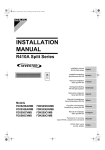
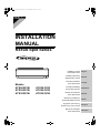
ATX20GV1B, ATX25GV1B, ATX35GV1B, ATX20JV1B, ATX25JV1B, ATX35JV1B
DAIKIN INDUSTRIES, LTD.
Shinri Sada
Manager Quality Control Department
11th. of Sep. 2009
Low Voltage 2006/95/EC
Electromagnetic Compatibility 2004/108/EC *
Umeda Center Bldg., 2-4-12, Nakazaki-Nishi,
Kita-ku, Osaka, 530-8323 Japan
74736-KRQ/EMC97-4957
KEMA Quality B.V.
DAIKIN.TCF.015 M12/09-2009
3SB64526-2D.fm Page 1 Tuesday, September 15, 2009 12:00 PM
3SB64526-2D
01_EN_3P207973-2D.fm Page 1 Friday, September 4, 2009 11:23 AM
Safety Precautions
• Read these Safety Precautions carefully to ensure correct installation.
• This manual classifies the precautions into WARNING and CAUTION.
Be sure to follow all the precautions below: they are all important for ensuring safety.
WARNING...............Failure to follow any of WARNING is likely to result in such grave consequences as death or serious injury.
CAUTION...............Failure to follow any of CAUTION may result in grave consequences in some cases.
• The following safety symbols are used throughout this manual:
Be sure to observe this instruction.
Be sure to establish an earth connection.
Never attempt.
• After completing installation, test the unit to check for installation errors. Give the user adequate instructions concerning the use
and cleaning of the unit according to the Operation Manual.
WARNING
• Installation should be left to the dealer or another professional.
Improper installation may cause water leakage, electrical shock, or fire.
• Install the air conditioner according to the instructions given in this manual.
Incomplete installation may cause water leakage, electrical shock, or fire.
• Be sure to use the supplied or specified installation parts.
Use of other parts may cause the unit to come to lose, water leakage, electrical shock, or fire.
• Install the air conditioner on a solid base that can support the weight of the unit.
An inadequate base or incomplete installation may cause injury in the event the unit falls off the base.
• Electrical work should be carried out in accordance with the installation manual and the national electrical wiring
rules or code of practice. Insufficient capacity or incomplete electrical work may cause electrical shock or fire.
• Be sure to use a dedicated power circuit. Never use a power supply shared by another appliance.
• For wiring, use a cable length enough to cover the entire distance with no connection.
Do not use an extension cord. Do not put other loads on the power supply, use a dedicated power circuit.
(Failure to do so may cause abnormal heat, electric shock or fire.)
• Use the specified types of wires for electrical connections between the indoor and outdoor units.
Firmly clamp the interconnecting wires so their terminals receive no external stresses. Incomplete connections or clamping may cause terminal overheating or fire.
• After connecting interconnecting and supply wiring be sure to shape the cables so that they do not put undue force
on the electrical covers or panels.
Install covers over the wires. Incomplete cover installation may cause terminal overheating, electrical shock, or fire.
• If any refrigerant has leaked out during the installation work, ventilate the room.
(The refrigerant produces a toxic gas if exposed to flames.)
• After all installation is complete, check to make sure that no refrigerant is leaking out.
(The refrigerant produces a toxic gas if exposed to flames.)
• When installing or relocating the system, be sure to keep the refrigerant circuit free from substances other than the
specified refrigerant (R410A), such as air.
(Any presence of air or other foreign substance in the refrigerant circuit causes an abnormal pressure rise or rupture, resulting in injury.)
• During pump-down, stop the compressor before removing the refrigerant piping.
If the compressor is still running and the stop valve is open during pump-down, air will be sucked in when the refrigerant piping is removed,
causing abnormal pressure in the freezer cycle which will lead to breakage and even injury.
• During installation, attach the refrigerant piping securely before running the compressor.
If the compressor is not attached and the stop valve is open during pump-down, air will be sucked in when the compressor is run, causing
abnormal pressure in the freezer cycle which will lead to breakage and even injury.
• Be sure to establish an earth. Do not earth the unit to a utility pipe, arrester, or telephone earth.
Incomplete earth may cause electrical shock, or fire. A high surge current from lightning or other sources may cause damage to the air conditioner.
• Be sure to install an earth leakage breaker.
Failure to install an earth leakage breaker may result in electric shocks, or fire.
CAUTION
• Do not install the air conditioner in a place where there is danger of exposure to inflammable gas leakage.
If the gas leaks and builds up around the unit, it may catch fire.
• Establish drain piping according to the instructions of this manual.
Inadequate piping may cause flooding.
• Tighten the flare nut according to the specified method such as with a torque wrench.
If the flare nut is tightened too hard, the flare nut may crack after a long time and cause refrigerant leakage.
1
■English
01_EN_3P207973-2D.fm Page 2 Friday, September 4, 2009 11:23 AM
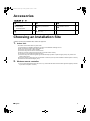
Accessories
A – L ,
A Mounting plate
1
E Remote controller holder
1
K Operation manual
1
B Titanium Apatite
Photocatalytic
Air-Purifying Filter
2
G AAA dry-cell batteries
2
L Installation manual
1
D Wireless remote controller
1
H Indoor unit fixing screws
(M4 × 12L)
2
Choosing an Installation Site
• Before choosing the installation site, obtain user approval.
1.
Indoor unit.
• The indoor unit should be sited in a place where:
1) the restrictions on installation specified in the indoor unit installation drawings are met,
2) both air intake and exhaust have clear paths met,
3) the unit is not in the path of direct sunlight,
4) the unit is away from the source of heat or steam,
5) there is no source of machine oil vapour (this may shorten indoor unit life),
6) cool (warm) air is circulated throughout the room,
7) the unit is away from electronic ignition type fluorescent lamps (inverter or rapid start type) as they may shorten the
remote control range,
8) the unit is at least 1 metre away from any television or radio set (unit may cause interference with the picture or sound),
9) install at the recommended height (1.8m).
2.
Wireless remote controller.
1) Turn on all the fluorescent lamps in the room, if any, and find the site where remote control signals are properly received
by the indoor unit (within 7 metres).
■English
2
01_EN_3P207973-2D.fm Page 3 Friday, September 4, 2009 11:23 AM
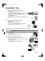
Installation Tips
1.
Removing and installing front panel.
• Removal method
1) Place your fingers in the indentations on the main unit (one each on the
left and right sides), and open the panel until it stops.
2) Continue to open the front panel further while sliding the panel to the right
and pulling it toward you in order to disengage the rotating shaft on the
left side. To disengage the rotating shaft on the right side, slide the panel
to the left while pulling it toward you.
Indentations on
the main unit
• Installation method
Align the tabs of the front panel with the grooves, and push all the way in. Then
close slowly. Push the center of the lower surface of the panel firmly to engage the
tabs.
2.
Rotating shaft
Push the rotating
shaft of the front
panel into the groove.
Removing and installing front grille.
Upper hook
¡¡¡ mark area
(3 locations)
• Removal method
1) Remove front panel to remove the air filter.
2) Remove the screws (2) from the front grille.
3) In front of the {{{ mark of the front grille, there are 3 upper hooks.
Lightly pull the front grille toward you with one hand, and push down on
the hooks with the fingers of your other hand.
Lightly pull the front
grille toward you with
one hand, and push
down on the hooks with
the fingers of your other
hand. (3 locations)
Push
down.
Upper hook
Upper hook
When there is no work space because the unit is close to ceiling
CAUTION
Be sure to wear protection gloves.
Place both hands under the center of the front grille, and while pushing up, pull it toward you.
1) Push up.
• Installation method
1) Install the front grille and firmly engage the upper hooks (3 locations).
2) Install 2screws of the front grille.
3) Install the air filter and then mount the front panel.
2) Pull toward you.
3.
How to set the different addresses.
JA
When two indoor units are installed in one room, the two wireless remote controllers
can be set for different addresses.
1) In the same way as when connecting to an HA system, remove the metal plate
electrical wiring cover.
2) Cut the address jumper (JA) on the printed circuit board.
3) Cut the address jumper (J4) in the remote controller.
JA ADDRESS
EXIST
CUT
1
2
J4
J4 ADDRESS
EXIST
CUT
3
1
2
■English
01_EN_3P207973-2D.fm Page 4 Friday, September 4, 2009 11:23 AM
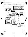
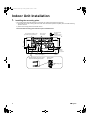
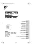
Indoor Unit Installation Drawings
How to attach the indoor unit.
Hook the claws of the bottom frame
to the mounting plate.
If the claws are difficult to hook,
remove the front grille.
How to remove the indoor unit.
Push up the marked area (at the
lower part of the front grille) to
release the claws. If it is difficult to Front grille
release, remove the front grille.
A Mounting plate
A Mounting
plate
Clip
Bottom frame
Mark (rear side)
The mounting plate
should be installed on a
wall which can support the
weight of the indoor unit.
Screws
(Field supply: M4 × 25L)
Caulk
pipe hole
gap
with putty.
30mm or more from ceiling
Front panel
Wrap the insulation pipe with
the finishing tape from bottom
to top.
50mm or more from walls
(on both sides)
Air filters
B Titanium Apatite Photocatalytic
Air-Purifying Filter (2)
Titanium Apatite
Photocatalytic
Air-Purifying Filter
Cut thermal insulation
pipe to an appropriate
length and wrap it with
tape, making sure that no
gap is left in the insulation
pipe’s cut line.
M4 × 16L
Service lid
Opening service lid
Service lid is opening/closing type.
Opening method
1) Remove the service lid screws.
2) Pull out the service lid diagonally
down in the direction of the arrow.
3) Pull down.
Air filter
Filter frame
Tab
D
Wireless
remote
controller
Screws
(Field supply: M3 × 20L)
■English
Before screwing the remote
controller holder to the wall,
make sure that control
signals are properly
received by indoor unit.
E
Remote
controller holder
4
01_EN_3P207973-2D.fm Page 5 Friday, September 4, 2009 11:23 AM
Indoor Unit Installation
1.
Installing the mounting plate.
• The mounting plate should be installed on a wall which can support the weight of the indoor unit.
1) Temporarily secure the mounting plate to the wall, make sure that the panel is completely level, and mark the boring
points on the wall.
2) Secure the mounting plate to the wall with screws.
Recommended mounting-plate retention spots and Dimensions
Recommended mounting - plate
retention spots (5 spots in all)
120.5
Use tape measure
as shown.
Position the end of
a tape measure at .
Place a leveler
on raised tab.
101
247
241.7
241.7
203
41.3
41.3
54.5
160
50
Gas pipe end
160
54
Throughthe-wall
hole φ65mm
331
330.5
770
Liquid pipe end
Drain hose
position
Keep here the piece cut out
from the unit for piping
* The removed pipe port cover can be
kept in the mounting plate pocket.
Removed pipe
port cover
A Mounting plate
5
■English
01_EN_3P207973-2D.fm Page 6 Friday, September 4, 2009 11:23 AM
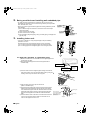
2.
Boring a wall hole and installing wall embedded pipe.
• For walls containing metal frame or metal board, be sure to use a wall
embedded pipe and wall cover in the feed-through hole to prevent possible
heat, electrical shock, or fire.
• Be sure to caulk the gaps around the pipes with caulking material to prevent
water leakage.
1) Bore a feed-through hole of 65mm in the wall so it has a down slope
toward the outside.
2) Insert a wall pipe into the hole.
3) Insert a wall cover into wall pipe.
4) After completing refrigerant piping, wiring, and drain piping, caulk pipe hole
gap with putty.
3.
φ
Installing indoor unit.
• In the case of bending or curing refrigerant pipes, keep the following
precautions in mind.
Abnormal sound may be generated if improper work is conducted.
1) Do not strongly press the refrigerant pipes onto the bottom frame.
2) Do not strongly press the refrigerant pipes on the front grille, either.
1)
2)
3-1. Right-side, right-back, or right-bottom piping.
1) Attach the drain hose to the underside of the refrigerant pipes with
an adhesive vinyl tape.
2) Wrap the refrigerant pipes and drain hose together with an
insulation tape.
Remove pipe port cover
here for right-side piping.
Right-back piping
Right-bottom
piping
Remove pipe port cover
here for right-bottom piping.
3) Pass the drain hose and refrigerant pipes through the wall hole,
then set the indoor unit on the mounting plate hooks by using the
markings at the top of the indoor unit as a guide.
4) Open the front panel, then open the service lid.
(Refer to Installation tips.)
5) Pass the interconnecting wires from the outdoor unit through the
feed-through wall hole and then through the back of the indoor
unit. Pull them through the front side. Bend the ends of tie wires
upward for easier work in advance. (If the interconnecting wire
ends are to be stripped first, bundle wire ends with adhesive
tape.)
6) Press the bottom frame of the indoor unit with both hands to set
it on the mounting plate hooks. Make sure the wires do not
catch on the edge of the indoor unit.
■English
Bind coolant pipe
and drain hose
together with
insulating tape.
A Mounting plate
Hang indoor unit’s hook here.
A Mounting plate
When stripping the
ends of interconnecting
wires in advance, bind
right ends of wires with
insulating tape.
Interconnecting
wires
Wire guide
6
01_EN_3P207973-2D.fm Page 7 Friday, September 4, 2009 11:23 AM
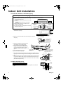
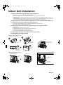
Indoor Unit Installation
3-2. Left-side, left-back, or left-bottom piping.
How to replace the drain plug and drain hose.
Drain hose attachment position
• Replacing onto the left side
1) Remove the insulation fixing screws on the right
to remove the drain hose.
2) Reattach the insulation fixing screw on the right
as it was.
* (Forgetting to attach this may cause water
leakages.)
3) Remove the drain plug on the left side and
attach it to the right side.
4) Insert the drain hose and tighten with included
indoor unit fixing screw.
* The drain hose is on the back of the unit.
Left side
Right side
Front side of unit
Attachment on the left side
Attachment on the right side (factory default)
Indoor unit
fixing screw
Insulation
fixing screw
Drain hose
Drain hose
1) Attach the drain hose to the underside of the refrigerant pipes
with adhesive vinyl tape.
Remove pipe
port cover
here for leftside piping.
Left-side
piping
Left-back
piping
Remove pipe port cover here for left-bottom piping.
Left-bottom piping
2) Be sure to connect the drain hose to the drain port in place of a
drain plug.
How to set drain plug.
ap.
No g
Do not apply lubricating
oil (refrigeration oil)
when inserting.
Application of causes
deterioration and drain
leakage of the plug.
Insert a hexagon wrench (4mm).
3) Shape the refrigerant pipe along the pipe
path marking on the mounting plate.
4) Pass drain hose and refrigerant pipes
through the wall hole, then set the indoor
unit on mounting plate hooks, using the
markings at the top of indoor unit as a
guide.
5) Pull in the interconnecting wires.
6) Connect the inter-unit piping.
Drain
hose
Caulk this hole
with putty or
caulking material.
7) Wrap the refrigerant pipes and drain hose together with insulation tape as
right figure, in case of setting the drain hose through the back of the indoor
unit.
8) While exercising care so that the interconnecting wires do not catch indoor
unit, press the bottom edge of indoor unit with both hands until it is firmly
caught by the mounting plate hooks. Secure indoor unit to the mounting
plate with screws (M4 × 12L).
A Mounting plate
Wrap insulating tape around the
bent portion of refrigerant pipe.
Overlap at least half the width of
the tape with each turn.
Bind with vinyl
tape.
Inter-unit wiring
Drain hose
A
Mounting
plate
Refrigerant
pipes
Bottom frame
H M4 × 12L (2 point)
3-3. Wall embedded piping.
Follow the instructions given under
Insert drain hose
Left-side, left-back, or left-bottom piping
1) Insert the drain hose to this depth so it won’t be pulled out of the drain
pipe.
to this depth so
Inner wall
it wont be pulled
out of drain pipe.
50mm
Drain hose
or more
Vinyl chloride
drain pipe
Outer wall
7
(VP-30)
■English
01_EN_3P207973-2D.fm Page 8 Friday, September 4, 2009 11:23 AM
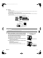
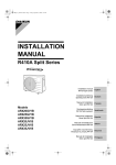
4.
Wiring.
1) Strip wire ends (15mm).
2) Match wire colours with terminal numbers on indoor and outdoor unit’s terminal blocks and firmly screw wires to the corresponding terminals.
3) Connect the earth wires to the corresponding terminals.
4) Pull wires to make sure that they are securely latched up, then retain wires with wire retainer.
5) In case of connecting to an adapter system. Run the remote control cable and attach the S21. (Refer to 5. When connecting to a
wired remote controller.)
6) Shape the wires so that the service lid fits securely, then close service lid.
1
2
3
Terminal block
Electrical component box
Shape wires so that the
service lid will fit securely.
Firmly secure wire retainer so that
wires sustain no external stress.
Use the specified
wire type.
Wire retainer
Firmly fix the wires with
the terminal screws.
Outdoor unit
When wire length exceeds
10m, use 2.0mm diameter wires.
Indoor
unit
1 23
LN
1
2
3
Firmly fix the wires with
the terminal screws.
H05RN
WARNING
1) Do not use tapped wires, strand wires, extensioncords, or starburst connections, as they may cause overheating, electrical
shock, or fire.
2) Do not use locally purchased electrical parts inside the product. (Do not branch the power for the drain pump, etc., from the
terminal block.) Doing so may cause electric shock or fire.
5.
When connecting to a wired remote controller.
* If work space is available on the right side of the indoor unit, the work
can be performed with the electrical component box attached. Omit the
steps involved with removing and installing the electrical component
box in order to perform the work more efficiently.
5-1. Remove the front grille (2 screws).
5-2. Remove the service lid (1 screw).
5-3. Remove the cover from the indoor unit electrical
component box [Figure 1].
* 5-4. Remove the indoor unit electrical component box.
1)
2)
3)
4)
5)
■English
Remove the flap.
Disconnect the communication wiring.
Disconnect the connector (S200).
Remove the thermistor from the heat exchanger.
Remove the electrical component box installation screw (1 screw).
Figure 1: Removing the cover from
the indoor unit electrical
component box
Disengage the tab.
Cover of the indoor unit
electrical component box
Disengage the tab.
8
01_EN_3P207973-2D.fm Page 9 Friday, September 4, 2009 11:23 AM
Indoor Unit Installation
5-5. Prepare the accessory (separate product) [Figure 2].
1) Remove the cover from the accessory (separate product).
2) Insert the connection cord into connector “S21” (white) in the accessory (separate product).
3) Route each of the connection cords through the cut-outs in the accessory, then reinstall the accessory cover in its
original position.
4) Insert the accessory (separate product) connector into connector “S403” in the indoor unit electrical component box.
Then route the connection cord through the cut-out in the indoor unit electrical component box.
5-6. Install the cover of the electrical component box in its original position [Figure 3].
5-7. Install the accessory (separate product) [Figure 3].
1) Install the accessory (separate product) into the indoor unit electrical component box.
2) Route the connection cord as shown in [Figure 3].
* 5-8. Install the indoor unit electrical component box in its original position.
1)
2)
3)
4)
5)
Install the flap.
Install the electrical component box (1 screw).
Install the thermistor in its original position on the heat exchanger.
Install the connector (S200) in its original position.
Connect the communication wiring in its original position.
5-9. Install the front grille in its original position (2 screws).
5-10. Install the service lid (1 screw).
Figure 2: Preparing the accessory
Accessory
Remove the accessory cover.
Insert “S403”.
Disengage the tab.
“S21”
Accessory cover
Route the connection
cords through the cut-outs.
Route each of the
connection cords.
Figure 3: Installing the accessory
Install the accessory cover
in its original position.
Cut-outs for the connection cords
Install the accessory.
Accessory
cover
Cut-out for the “S403”
connection
Cut-out for the
connection cord
Accessory
9
■English
01_EN_3P207973-2D.fm Page 10 Friday, September 4, 2009 11:23 AM
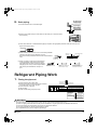
6.
Drain piping.
The drain hose should
be inclined downward.
1) Connect the drain hose, as described right.
No trap is permitted.
Do not put the end
of the hose in water.
2) Remove the air filters and pour some water into the drain pan to check the water
flows smoothly.
3) If drain hose extension or embedded drain piping is required, use appropriate parts that match the hose front end.
[Figure of Hose Front End]
φ18
4) When extending the drain hose, use a commercially available
extension hose with an inner diameter of 16 mm.
Be sure to thermally insulate the indoor section of the extension
hose.
Indoor unit
drain hose
φ16
The drain hose provided
to indoor unit.
5) When connecting a rigid polyvinyl chloride pipe
(nominal diameter 13mm) directly to the drain
hose attached to the indoor unit as with embedded piping work, use any commercially available
drain socket (nominal diameter 13mm) as a
joint.
Extension drain hose
φ16
φ16
Heat insulation tube
(Field supply)
φ18
The drain hose provided
to indoor unit.
Commercially available drain
socket
(nominal diameter 13mm)
Commercially available rigid
polyvinyl chloride pipe
(nominal diameter 13mm)
Refrigerant Piping Work
1.
Flaring the pipe end.
1) Cut the pipe end with a pipe cutter.
2) Remove burrs with the cut surface facing downward
so that the chips do not enter the pipe.
3) Put the flare nut on the pipe.
4) Flare the pipe.
5) Check that the flaring is properly made.
(Cut exactly at
right angles.)
Remove burrs
Flaring
Set exactly at the position shown below.
A
Die
A
Flare tool for R410A
Conventional flare tool
Clutch-type
Clutch-type (Rigid-type) Wing-nut type (Imperial-type)
0-0.5mm
1.0-1.5mm
1.5-2.0mm
Check
Flare’s inner
surface must
be flaw-free.
The pipe end must
be evenly flared in
a perfect circle.
Make sure that the
flare nut is fitted.
WARNING
1)
2)
3)
4)
5)
6)
Do not use mineral oil on flared part.
Prevent mineral oil from getting into the system as this would reduce the lifetime of the units.
Never use piping which has been used for previous installations. Only use parts which are delivered with the unit.
Do never install a drier to this R410A unit in order to guarantee its lifetime.
The drying material may dissolve and damage the system.
Incomplete flaring may cause refrigerant gas leakage.
■English
10
01_EN_3P207973-2D.fm Page 11 Friday, September 4, 2009 11:23 AM
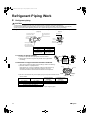
Refrigerant Piping Work
2.
Refrigerant piping.
CAUTION
1) Use the flare nut fixed to the main unit. (To prevent cracking of the flare nut by aged deterioration.)
2) To prevent gas leakage, apply refrigeration oil only to the inner surface of the flare. (Use refrigeration oil for R410A.)
3) Use torque wrenches when tightening the flare nuts to prevent damage to the flare nuts and gas leakage.
Align the centres of both flares and tighten the flare nuts 3 or 4 turns by hand. Then tighten them fully with the torque wrenches.
[Apply oil]
[Tighten]
Apply refrigeration oil to
the inner surface of the
flare.
Do not apply refrigeration
oil to the outer surface.
Torque wrench
Flare nut
Spanner
Piping union
Flare nut
Do not apply refrigeration
oil to the flare nut avoid
tightening with over torque.
Flare nut tightening torque
Gas side
Liquid side
3/8 inch
1/4 inch
32.7-39.9N l m
(330-407kgf l cm)
14.2-17.2N l m
(144-175kgf l cm)
2-1. Caution on piping handling.
1) Protect the open end of the pipe against dust and moisture.
2) All pipe bends should be as gentle as possible. Use a pipe bender
for bending.
2-2. Selection of copper and heat insulation materials.
• When using commercial copper pipes and fittings, observe the following:
1) Insulation material: Polyethylene foam
Heat transfer rate: 0.041 to 0.052W/mK (0.035 to 0.045 kcal/(mh•°C))
Refrigerant gas pipe’s surface temperature reaches 110°C max.
Choose heat insulation materials that will withstand this temperature.
2) Be sure to insulate both the gas and liquid piping and to provide insulation dimensions as below.
Gas side
Liquid side
O.D. 9.5mm
O.D. 6.4mm
Minimum bend radius
30mm or more
Thickness 0.8mm (C1220T-O)
Inter-unit wiring
Gas pipe
Liquid pipe
Gas pipe
insulation
Liquid pipe
insulation
Finishing tape
Drain hose
Gas pipe thermal
Liquid pipe thermal
insulation
insulation
I.D. 12-15mm
I.D. 8-10mm
Thickness 10mm Min.
3) Use separate thermal insulation pipes for gas and liquid refrigerant pipes.
11
■English
01_EN_3P207973-2D.fm Page 12 Friday, September 4, 2009 11:23 AM
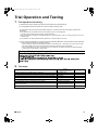
Trial Operation and Testing
1.
Trial operation and testing.
1-1 Measure the supply voltage and make sure that it falls in the specified range.
1-2 Trial operation should be carried out in either cooling or heating mode.
• In cooling mode, select the lowest programmable temperature; in heating mode, select the highest programmable
temperature.
1) Trial operation may be disabled in either mode depending on the room temperature.
Use the remote controller for trial operation as described below.
2) After trial operation is complete, set the temperature to a normal level (26°C to 28°C in cooling mode, 20°C to 24°C in
heating mode).
3) For protection, the system disables restart operation for 3 minutes after it is turned off.
1-3 Carry out the test operation in accordance with the Operation Manual to ensure that all functions and parts,
such as louver movement, are working properly.
• The air conditioner requires a small amount of power in its standby mode. If the system is not to be used for some
time after installation, shut off the circuit breaker to eliminate unnecessary power consumption.
• If the circuit breaker trips to shut off the power to the air conditioner, the system will restore the original operation
mode when the circuit breaker is opened again.
! " ! #
$% & # ' ( ") # * + 2.
Test items.
Test items
Indoor and outdoor units are installed properly on solid bases.
Symptom
(diagnostic display on RC)
Fall, vibration, noise
No refrigerant gas leaks.
Incomplete cooling/heating function
Refrigerant gas and liquid pipes and indoor drain hose extension are thermally insulated.
Water leakage
Draining line is properly installed.
Water leakage
System is properly earthed.
Electrical leakage
The specified wires are used for interconnecting wire connections.
Inoperative or burn damage
Indoor or outdoor unit’s air intake or exhaust has clear path of air.
Stop valves are opened.
Incomplete cooling/heating function
Indoor unit properly receives remote controller commands.
Inoperative
■English
Check
12
00_CV_3P207973-2D.fm Page 2 Friday, September 4, 2009 11:19 AM
Two-dimensional bar code is a code
for manufacturing.
3P207973-2D M07B063C
(0911) HT