1
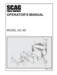
CLASSIC
OPERATOR’S
MANUAL
Leaf Blower
Model:
LBC15-SP170
Congratulations on owning a Scag Giant-Vac blower! This manual contains the
operating instructions and safety information for your Scag Giant-Vac blower.
Reading this manual can provide you with assistance in maintenance and
adjustment procedures to keep your blower performing to maximum efficiency.
The specific models that this book covers are listed on the inside cover. Before
operating your blower, please read all the information enclosed.
© 2013
Scag Giant-Vac
Division of Metalcraft of Mayville, Inc.
PART NO. 03347
PRINTED 7/2013
PRINTED IN USA
WARNING
FAILURE TO FOLLOW SAFE OPERATING PRACTICES MAY RESULT
IN SERIOUS INJURY OR DEATH.
• Read this manual completely as well as other manuals that came with your blower.
• ALWAYS FOLLOW OSHA APPROVED OPERATION.
• Become familiar with the safe operation of the equipment, operator controls and
safety signs.
• DO NOT operate on steep slopes.
• Always travel across slopes.
• Keep all shields in place, especially the discharge chute.
• Before performing any maintenance or service, stop the machine and remove the
spark plug wire.
• If a mechanism becomes clogged, stop the engine before cleaning.
• Keep hands, feet and clothing away from power-driven parts.
REMEMBER - YOUR BLOWER IS ONLY AS SAFE AS THE OPERATOR!
Hazard control and accident prevention are dependent upon the awareness,
concern, prudence, and proper training of the personnel involved in the
operation, transport, maintenance, and storage of the equipment.
This manual covers the operating instructions and illustrated parts list for:
LBC15-SP170
with a serial number of
001A00001 to 001A99999
Always use the entire serial number listed on the serial number tag when referring to this product.
Table of Contents
Table of Contents
SECTION 1 - GENERAL INFORMATION. ..................................................................................1
1.1 Introduction............................................................................................................................................1
1.2 Direction Reference............................................................................................................................1
1.3 Servicing The Engine And Drive Train Components..................................................................1
1.4 Symbols.....................................................................................................................................................2
SECTION 2 - SAFETY INFORMATION.......................................................................................3
2.1 Introduction............................................................................................................................................3
2.2 Signal Words...........................................................................................................................................3
2.3 Before Operation Considerations.................................................................................................3
2.4 Operation Considerations.................................................................................................................4
2.5 Maintenance Considerations & Storage.....................................................................................5
2.6 Using a spark arrestor......................................................................................................................5
2.7 sPARK IGNITION SYSTEM..........................................................................................................................5
2.8 Safety And Instructional Decals..................................................................................................6
SECTION 3 - SPECIFICATIONS.................................................................................................7
3.1 ENGINE.........................................................................................................................................................7
3.2 bLOWER.......................................................................................................................................................7
3.3 Weights and Dimensions......................................................................................................................7
SECTION 4 - OPERATING INSTRUCTIONS..............................................................................9
4.1 CONTROLS AND INSTRUMENT IDENTIFICATION ...................................................................................9
4.2 INITIAL RUN-IN PROCEDURES...................................................................................................................9
4.3 STARTING THE ENGINE............................................................................................................................10
4.4 HILLSIDE OPERATION...............................................................................................................................10
4.5 PARKING THE BLOWER............................................................................................................................10
4.6 AFTER OPERATION...................................................................................................................................10
4.7 REMOVING CLOGGED MATERIAL...........................................................................................................11
4.8 RECOMMENDATIONS FOR blowing.....................................................................................................11
I
Table of Contents
SECTION 5 - MAINTENANCE. .................................................................................................12
5.1 MAINTENANCE CHART - RECOMMENDED SERVICE INTERVALS.......................................................12
5.2 Engine Oil................................................................................................................................................13
5.3 Engine Fuel System.............................................................................................................................13
5.4 Engine Air Cleaner..............................................................................................................................13
5.5 TIRES...........................................................................................................................................................13
SECTION 6 - ILLUSTRATED PARTS LIST...............................................................................14
4.1 SCAG Giant-Vac APPROVED ATTACHMENTS AND ACCESSORIES..................................................14
NOTES...............................................................................................................................................................15
CLASSIC BLOWER ASSEMBLY......................................................................................................................16
CLASSIC BLOWER DECALS...........................................................................................................................18
LIMITED WARRANTY - CLASSIC LEAF BLOWER.................................Inside Back Cover
II
Section 1
GENERAL INFORMATION
1.1 Introduction
WARNING
Your Scag Giant-Vac product was built to the highest
standards in the industry. However, the prolonged life
and maximum efficiency of your blower depends on you
following the operating, maintenance and adjustment
instructions in this manual.
For pictorial clarity, some illustrations and figures
in this manual may show shields, guards or plates
open or removed. Under no circumstances should
this product be operated without these devices
in place.
If additional information or service is needed, contact your
Scag Giant-Vac Dealer.
All information is based upon product information available
at the time of approval for printing. Scag Giant-Vac
reserves the right to make changes at any time without
notice and without incurring any obligation.
We encourage you to contact your dealer for repairs.
All Scag Giant-Vac dealers are informed of the latest
methods to service this equipment and provide prompt
and efficient service in the field or at their service shop.
They carry a full line of Scag Giant-Vac service parts.
1.2 Direction Reference
- IMPORTANT -
The “Right” and “Left”, “Front” and “Rear” of the machine
are referenced from the operator’s right and left when in
the normal operating position and facing the forward travel
direction.
The replacement of any part on this product
by other than the manufacturer's authorized
replacement part may adversely affect the
performance, durability or safety of this
product.
1.3 Servicing The Engine And Drive
Train Components
Use of other than original Scag Giant-Vac
replacement parts will void the warranty.
Details regarding the service and repair of the engine
are not covered in this manual; only routine maintenance
and general service instructions are provided. For service
of these components during the limited warranty period,
it is important to contact your Scag Giant-Vac dealer or
find a local authorized servicing agent of the component
manufacturer. Any unauthorized work done on these
components during the warranty period may void your
warranty.
When ordering parts, always give the model and serial
number of your product. The serial number plate is located
on the frame next to the engine.
USE ONLY SCAG Giant-vac APPROVED
ATTACHMENTS AND ACCESSORIES.
Attachments and accessories manufactured by companies
other than Scag Giant-Vac are not approved for use on
this machine. See Section 6-1.
1
Section 1
1.4 Symbols
SYMBOL
DESCRIPTION
SYMBOL
DESCRIPTION
Choke
Transmission
On/Start
Spring Tension on Idler
Off/Stop
Oil
Spinning Fan Blades
Thrown Object Hazard
Fast
Slow
Continuously Variable - Linear
Pinch Point
481039S
Keep Bystanders Away
Read Operator's Manual
2
Section 2
SAFETY INFORMATION
2.1 Introduction
Danger
Your blower is only as safe as the operator. Carelessness
or operator error may result in serious bodily injury
or death. Hazard control and accident prevention are
dependent upon the awareness, concern, prudence,
and proper training of the personnel involved in the
operation, transport, maintenance and storage of the
equipment. Make sure every operator is properly trained
and thoroughly familiar with all of the controls before
operating. The owner/user can prevent and is responsible
for accidents or injuries occurring to themselves, other
people or property.
The signal word “DANGER” denotes that an extremely
hazardous situation exists on or near the machine that
could result in high probability of death or irreparable
injury if proper precautions are not taken.
Warning
The signal word “WARNING” denotes that a hazard exists
on or near the machine that can result in injury or death if
proper precautions are not taken.
R E A D T H I S O P E R ATO R ’ S M A N UA L B E F O R E
ATTEMPTING TO START YOUR BLOWER.
A replacement manual is available from your authorized
Scag Giant-Vac Dealer or by contacting Scag Giant-Vac,
Service Department at P.O. Box 152, Mayville, WI 53050
or contact us via the Internet at www.giant-vac.com. The
manual for this machine can be downloaded by using
the model and serial number or use the contact form to
make your request. Please indicate the complete model
and serial number of your Scag Giant-Vac product when
requesting replacement manuals.
Caution
The signal word “CAUTION” is a reminder of safety
practices on or near the machine that could result in
personal injury if proper precautions are not taken.
Your safety and the safety of others depends significantly
upon your knowledge and understanding of all correct
operating practices and procedures of this machine.
2.2 Signal Words
2.3 Before Operation
Considerations
1. NEVER allow children to operate this machine. Do
not allow adults to operate this machine without
proper instructions.
This symbol means “Attention! Become Alert! Your
Safety is Involved!" The symbol is used with the following
signal words to attract your attention to safety messages
found on the decals on the machine and throughout this
manual. The message that follows the symbol contains
important information about safety. To avoid injury and
possible death, carefully read the message! Be sure to
fully understand the causes of possible injury or death.
2. Do not operate when children and/or others are
present. Keep children out of the work area and in
the watchful care of a responsible adult other than
the operator. Be alert and turn machine off if a child
enters the area.
3. DO NOT allow children to ride or play on the
machine, it is not a toy.
Signal Word:
4. DO NOT operate the machine under the influence of
alcohol or drugs.
It is a distinctive word found on the safety decals on the
machine and throughout this manual that alerts the viewer
to the existence and relative degree of the hazard.
5. If the operator(s) or mechanic(s) cannot read
English, it is the owner's responsibility to explain this
material to them.
3
Section 2
6. DO NOT wear loose fitting clothing. Loose clothing,
jewelry or long hair could get tangled in moving
parts. Do not operate the machine wearing shorts;
always wear adequate protective clothing including
long pants. Wearing safety glasses, safety shoes and
a helmet is advisable and is required by some local
ordinances and insurance regulations.
2.4 Operation Considerations
1. Know the function of all controls and how to stop
quickly.
2. Do not operate on slopes if you are uneasy or
uncertain. Ultimate responsibility for safe operation
on slopes rests with the operator.
3. Exercise extreme caution when operating on slopes.
Keep all movements slow and gradual. Be sure of
your footing.
WARNING
4. Do not turn on slopes unless absolutely necessary.
Turn slowly and downhill when possible.
Always wear hearing protection. Operating this
machine over prolonged periods of time can
cause loss of hearing.
5. Do not operate on steep slopes. Poor footing could
cause a slip and fall accident.
7. Keep the machine and attachments in good
operating condition. Keep all shields and safety
devices in place. If a shield, safety device or decal
is defective or damaged, repair or replace it before
operating the machine.
6. When using this machine, never direct the blown
material toward bystanders or allow anyone near the
machine while in operation.
7. Do not blow material towards cars, windows, or other
items which could be injured or damaged by blown
debris.
8. Fuel is flammable; handle it with care. Fill the fuel
tank outdoors. Never fill it indoors. Use a funnel or
spout to prevent spillage. Clean up any spillage
before starting the engine.
8. Before attempting to start the engine, inspect the
machine, shields and safety devices for any damage.
Correct any problems before operating.
9. DO NOT add fuel to a running or hot engine. Allow
the engine to cool for several minutes before adding
fuel. Never fuel indoors or inside enclosed trailers.
9. If the blower ever plugs, shut off the engine, and
wait for all movement to stop before removing the
obstruction.
10. See Section 7.5 ENGINE FUEL SYSTEM for fueling
procedure.
WARNING
11. Keep flammable objects (cigarettes, matches, etc.),
open flames and sparks away from the fuel tank and
fuel container. Use only approved containers.
DO NOT use your hand to dislodge the clogged
material. Use a stick or other device to remove
clogged material after the engine has stopped
running and the blower fan have stopped
turning.
12. Do not operate without the side deflector installed.
13. Check the engine mounting bolts at frequent
intervals for proper tightness.
10. If the machines begins to vibrate abnormally, shut
the machine off immediately. Inspect the machine
and have repairs made before restarting.
11. Be alert for holes, rocks, roots and other hidden
hazards in the terrain. Cautiously enter a new area.
Be alert for hidden hazards.
12. Do not operate near drop-offs, ditches or
embankments. You could lose your footing, balance
or drive the machine off the edge.
4
Section 2
13. Use only in daylight or good artificial light.
2. Do not straighten or weld the blower fan. Replace
damaged or failed blower fans.
14. Do not leave the machine unattended.
3. Disconnect spark plug wire to prevent accidental
starting of the engine when servicing or adjusting
the machine. Wait for all movement to stop before
adjusting, cleaning or repairing.
15. The machine and attachments should be stopped
and inspected for damage after striking a foreign
object, and damage should be repaired before
restarting and operating the machine.
4. Keep all nuts, bolts and screws tight, to ensure the
machine is in safe working condition.
16. Keep hands and feet away from blower intake and
outlet. Contact can injure.
5. Do not change the engine governor settings or
overspeed the engine. See the engine operator's
manual for information on engine settings.
Caution
6. To reduce fire hazard, keep the muffler and engine
free of grass, leaves, excessive grease, oil and dirt.
Do not touch the engine or the muffler while the
engine is running or immediately after stopping.
These areas may be hot enough to cause a
burn.
7. Park the machine on level ground.
8. NEVER allow untrained personnel to service the
machine.
9. Keep all parts in good working condition. Replace all
worn or damaged decals.
DANGER
10. Use jack stands to support components when
required.
11. Let the engine cool before storing.
DO NOT run the engine inside a building or
a confined area without proper ventilation.
Exhaust fumes are hazardous and contain
carbon monoxide which can cause brain injury
and death.
12. DO NOT store the machine near an open flame.
13. Shut off fuel while storing or transporting.
14. DO NOT store fuel near flames or drain indoors.
2.6 Using a spark arrestor
17. Keep hands and feet away from all other moving
parts. Contact can injure.
The engine in this machine is not equipped with a spark
arrestor muffler. It is in violation of California Public
Resource Code Section 4442 to use or operate this
engine on or near any forest covered, brush covered or
grass covered land unless the exhaust system is equipped
with a spark arrestor meeting any applicable local or state
laws. Other states or federal areas may have similar laws.
Check with your state or local authorities for regulations
pertaining to these requirements.
18. Use extra care when loading or unloading the
machine into a truck or trailer.
19. Tie the blower down securely using straps, chains,
cable, or ropes. Both front and rear straps must be
directed down and outward from machine.
20. Use care when approaching blind corners, shrubs,
trees, or other objects that may obscure vision.
21. NEVER leave the machine running unattended.
2.7 sPARK IGNITION SYSTEM
2.5 Maintenance Considerations &
Storage
This spark ignition system complies with Canadian
ICES-002.
1. Never make adjustments to the machine with the
engine running unless specifically instructed to do
so. If the engine is running, keep hands, feet, and
clothing away from moving parts.
5
Section 2
2.8 Safety And Instructional Decals
484983
485073
6
Section 3
SPECIFICATIONS
3.1 ENGINE
General Type.................................................................................................Heavy Duty Industrial/Commercial Gasoline
Brand...................................................................................................................................................................... Subaru
Engine Model:
(Scag Giant-Vac Model LBX9152S).........................................................................................Subaru Model # SP170
Displacement:
Subaru SP170..................................................................................................................................................... 169cc
Cylinders........................................................................................................................................ 1 with Cast-Iron Sleeve
Governor...................................................Centrifugal Flywheel Type Set to 3,600 RPM at maximum load (+/- 100 RPM)
Idle Speed:
Subaru................................................................................................................................. 1,400 RPM (+/- 150 RPM)
Carburetor..........................................................................................................................................................Float Type
Fuel....................................................................................... Non-Leaded Gasoline with a Minimum Octane Rating of 87
Fuel Capacity......................................................................................................................................... 0.95 Gallon (3.4L)
Lubrication Type.......................................................................................................................... Mechanical Splash Type
Oil Capacity....................................................................................................................................... 0.260 Gallon (0.98L)
Starter:
Subaru..................................................................................................................................................... Recoil Starter
Ignition System............................................................................................................Solid State Transistorized Magneto
Air Filter........................................................................................................................................................ Dual Element
3.2 bLOWER
Impeller Diameter.................................................................................................................................Balanced 15" Steel
Number of Blades........................................................................................................................................................ 4
CFM (cubic feet / min.)............................................................................................................................................... 1392
Discharge Control.............................................................................................................................................Front / Side
3.3 Weights and Dimensions
Length...........................................................................................................................................................................43"
Width.............................................................................................................................................................................27"
Height............................................................................................................................................................................40"
Weight........................................................................................................................................................................ 102#
Wheels:
(1) Front................................................................................................................................ 6 X 1.50 Semi-Pneumatic
(2) Rear...............................................................................4.10 X 3.50-4 Two-Ply Pneumatic Tubeless, Radius Edge
Tire Pressure:
Rear.................................................................................................................................................................... 20 PSI
7
Section 3
8
Section 4
OPERATING INSTRUCTIONS
2. Engine Choke Control (Figure 4-1). Used to start
a cold engine.
CAUTION
3. Engine Throttle Control (Figure 4-1). Used to
control the engine speed. Pushing the lever forward
increases engine speed. Pulling the lever back
decreases engine speed. Full back position is the
IDLE position.
Do not attempt to operate this blower unless you
have read this manual. Learn the location and
purpose of all controls and instruments before
you operate.
4. Fuel Control Lever (Figure 4-1). Used to control
the fuel supply to the engine.
4.1 CONTROLS AND INSTRUMENT
IDENTIFICATION
4.2 INITIAL RUN-IN PROCEDURES
First Day of Use or Approximately 20 Hours
Before operating the blower, familiarize yourself with all
blower and engine controls. Knowing the location, function
and operation of these controls is important for safe and
efficient operation.
1. Change the engine oil and oil filter after the first 20
hours of operation. (See Section 5.2.)
2. Check for loose hardware. Tighten as needed.
1. Ignition Switch (Figure 4-1). The ignition switch
is used to start the engine. Turn the knob to
the on position before pulling the recoil starter.
3. Check tire pressure. Adjust pressure if necessary.
(See Section 5.5.)
ENGINE THROTTLE
CONTROL
ENGINE CHOKE
CONTROL
FUEL CONTROL
LEVER
IGNITION
SWITCH
Figure 4-1. Controls and Instruments
9
Section 4
4.3 STARTING THE ENGINE
4.5 PARKING THE BLOWER
1. Park the machine on a flat, level surface only. Do not
park the machine on an incline.
CAUTION
2. Slow the engine to idle speed.
3. Turn the ignition switch to the OFF position.
DO NOT USE STARTING FLUIDS. Use of starting
fluids in the air intake system may be potentially
explosive or cause a “runaway” engine condition
that could result in engine damage and/or
personal injury.
4.6 AFTER OPERATION
1. Wash the entire blower after each use. Do not
use high pressure spray or direct the spray onto
electrical components.
1. Be sure the fuel control lever, located on the left side
of the engine, is completely open. See Figure 4-1.
- IMPORTANT Do not wash a hot or running engine. Cold water
will damage the engine. Use compressed air to
clean the engine if it is hot.
2. If the engine is cold, choke the engine as needed.
3. Move the engine throttle control to about half engine
speed.
2. Keep the entire blower clean to inhibit serious heat
damage to the engine.
4. Turn the ignition switch to the ON position.
5. Pull the recoil starter on the engine.
3. Check the tire pressure. Adjust pressure if
necessary.
6. Allow engine to warm before operating the blower.
4.4 HILLSIDE OPERATION
WARNING
DO NOT operate on steep slopes. Poor footing
could cause a slip and fall accident. ALWAYS
FOLLOW OSHA APPROVED OPERATION.
1. Do not operate on slopes if you are uneasy or
uncertain. Unltimate responsibility for safe operation
on slopes rests with the operator.
2. Be sure of footing on slopes.
3. Caution must be used when operating on slopes,
especially when the grass is wet. Wet grass reduces
traction and control.
4. To prevent tipping or loss of control, keep all
movements on slopes slow and gradual.
5. Do not turn on slopes unless necessary, and then
turn slowly and down hill when possible.
6. Be alert for holes, rocks, roots and other hidden
hazards in the terrain. Uneven terrain could cause a
slip and fall accident.
7. Keep tires properly inflated.
10
Section 4
4.7 REMOVING CLOGGED MATERIAL
Danger
ROTATING FAN BLADES
NEVER PUT YOUR HANDS INTO THE AIR INTAKE
OR OUTLET FOR ANY REASON!
Shut off the engine, remove the spark plug wire
and only then use a stick or similar object to
remove material if clogging has occurred.
1. If the air intake or outlet becomes clogged, shut off
the engine and remove the spark plug wire. Using a
stick or similar item, dislodge the clogged material.
Then resume normal operation.
4.8 RECOMMENDATIONS FOR blowing
Air flow can be directed to the side or front by adjusting
the two-position deflector. The front discharge position is
used to remove debris from along retaining walls, fences,
etc. The side discharge position to form windrows and/
or piles. The air speed of the blower is regulated by the
engine throttle.
1. To reduce windrowing or to blow over an obstacle,
point the deflector upwards.
WARNING
DO NOT operate without Two-Position Deflector
properly installed.
2. To avoid blowing into an area, close the deflector
and reduce the throttle setting.
3. Plan how to clear a yard or parking lot to reduce
clearing time.
4. Keep blower intake and outlet clean.
5. Use a slow travel speed when clearing heavy or
large amounts of material.
6. Operate the engine at full throttle for best results.
The engine is designed to be operated at full speed.
11
Section 5
MAINTENANCE
5.1 MAINTENANCE CHART - RECOMMENDED SERVICE INTERVALS
HOURS
Break-In
(First 10)
8
20
50
100
200
Procedure
500
X
Comments
Check all hardware for tightness
X
Check engine oil level
X
*Clean blower
X
Check tire pressure
X
Check condition of fan blades
X
X
See engine operator's
manual
Change engine oil and filter
See engine operator's
manual
*Clean air filter element
See engine operator's
manual
X
Check condition of fuel lines
X
Check all hardware for tightness
X
Change engine oil
See engine operator's
manual
X
*Clean air cleaner element
See engine operator's
manual
X
*Clean Fuel Cup
See engine operator's
manual
X
*Replace engine air filter
See engine operator's
manual
X
Clean and Adjust Spark Plug
See engine operator's
manual
Replace Spark Plug
See engine operator's
manual
X
* Perform these maintenance procedures more frequently under extreme dusty or dirty conditions
12
Section 5
5.2 Engine Oil
4. Never remove the gas cap or add fuel with the
engine running. Allow the engine to completely cool
before fueling.
A. Checking Engine Crankcase Oil Level
5. Never fuel the machine indoors or in an enclosed
trailer.
The engine oil level should be checked after every 8 hours
of operation or daily as instructed in the Engine Operator’s
Manual furnished with this blower.
6. Never store the machine or fuel container where
there is an open flame, spark or pilot light such as on
a water heater or other appliances.
B. Changing Engine Crankcase Oil
7. Never fill containers inside a vehicle or on a truck
or trailer bed with a plastic liner. Always place
containers on the ground away from your vehicle
before filling.
After the first 20 hours of operation, change the engine
crankcase oil and replace the oil filter. Thereafter,
change the engine crankcase oil after every 100 hours
of operation or bi-weekly, whichever occurs first. Refer to
the Engine Operator’s Manual furnished with this blower
for instructions.
8. Remove the machine from the truck or trailer and
fuel on level ground. If this is not possible, then refuel
the machine with a portable container, rather than
from a gasoline dispenser nozzle.
9. Keep the nozzle in contact with the rim of fuel tank
or container opening at all times until fueling is
complete. Do not use a nozzle lock-open device.
5.3 Engine Fuel System
DANGER
10. If fuel is spilled on clothing, change clothing
immediately and wash affected skin.
11. Replace gas cap and tighten securely.
To avoid injury from burns, allow the blower
to cool before removing the fuel tank cap and
refueling.
5.4 Engine Air Cleaner
A. Cleaning and/or Replacing Air
Cleaner Element
A. Filling the Fuel Tank
Fill the fuel tank at the beginning of each operating day. Fill
to the top of the fuel filter screen (approximately 0.9 gallon)
at the beginning of each operating day. Do not overfill. Use
clean, fresh unleaded gasoline with a minimum octane
rating of 87 and a maximum of 10% Ethanol.
For any air cleaner, the operating environment dictates
the air cleaner service periods. Inspect and clean the air
cleaner element after every 200 hours of operation or
monthly, whichever occurs first and replace the element if
required. Refer to the Engine Operator’s Manual furnished
with this blower for instructions.
DO NOT use E85 Fuel. Using E85 Fuel will cause severe
damage to the engine.
- NOTE In extremely dusty conditions it may be necessary
to check the element once or twice daily to prevent
engine damage.
To avoid personal injury or property damage, use extreme
care in handling gasoline. Gasoline is extremely flammable
and the vapors are explosive.
5.5 TIRES
1. Extinguish all cigarettes, cigars, pipes and other
sources of ignition.
2. Use only an approved gasoline container.
Check the tire pressures after every 8 hours of operation
or daily.
3. When filling the fuel tank, always use the fuel filter
screen.
13
Caster Wheels
20 PSI
Section 6
ILLUSTRATED PARTS LIST
4.1 SCAG Giant-Vac APPROVED ATTACHMENTS AND ACCESSORIES.
Attachments and accessories manufactured by companies other than Scag Giant-Vac are not approved for
use on this machine.
14
Section 6
NOTES
15
Section 6
CLASSIC BLOWER ASSEMBLY
1
4
2
1
3
5
6
40
14
39
41
8
8
7
11
12
10
13
38
36
A
A
16
17
32
15
19
31
32
37
35
8
18
33
9
23
25
24
20
22
18
29
26
26
27
28
30
16
22
21
Section 6
CLASSIC BLOWER ASSEMBLY
Ref.
No.
1
2
3
4
5
6
7
8
9
10
11
12
13
14
15
16
17
18
19
20
21
22
23
24
25
26
27
28
29
30
31
32
33
34
35
36
37
38
39
40
41
Part No.
462618
485074
485006
04001-05
04021-08
484928
44200
04019-02
04117-01
04050-09
484764
484840
44203
04017-16
04040-15
426339
484843
04019-02
04019-03
484844
485008
485009
485010
04001-08
426341
04003-02
426169
484845
04117-01
04001-31
04021-09
462606
452494
04102-09
04030-04
04041-11
462629
04117-01
04063-05
484951
04001-11
04003-15
Description
Handle, Upper w / Grip - LBC
Grip, 1" x 25-1/2"
Cable, Throttle Control
Bolt, Hex Head 1/4-20 x 2"
Nut, Elastic Stop 1/4-20
Handle, Lower Folding - LBC
Loop
Nut, Serrated Flange 1/4-20
Nut, Elastic Stop 5/16-18
Retaining Ring
Spring, Air Discharge Door
Knob, Ball 3/8-16 Thread
Rod, Air Control
Bolt, Hex Head Serrated Flange 5/16-18 x 3/4"
Flatwasher, 5/16-18 - .375 x .875 x .083
Deflector, Side Air
Mount, Vibration
Nut, Serrated Flange 1/4-20
Nut, Serrated Flange 5/16-18
Wheel Assembly (incl. #20, 21, 22)
Tire
Rim w / Valve
Bearing
Bolt, Hex Head 5/16-08 x 3/4"
Door, Forward Air Control
Bolt, Carriage 1/4-20 x 3/4"
Bracket, Caster
Wheel
Nut, Flange Elastic Stop Nut 5/16-18
Bolt, Hex Head 3/8-16 x 2-1/2"
Nut, Elastic Stop 3/8-16
Baffle Weldment, Intake w / Decal
Impeller Weldment, LBC 15 x 3/4" Bore
Bolt, Hex Head 5/16-24 x 2" w / Patch
Lockwasher, 3/8" Spring
Flatwasher, 3/8-.406 x 1.50 x 7 Ga.
Blower Housing Weldment w / Decals - LBC
Nut, Flange Elastic Stop 5/16-18
Key, 3/16 x 3/16 x 1-1/2"
Engine, Subaru SP170 (not available through Scag Giant-Vac)
Bolt, Hex Head 5/16-18 x 1-1/2"
Bolt, Carriage 5/16-18 x 1-3/4"
17
Section 6
CLASSIC BLOWER DECALS
484983
485044
485073
484984
18
LIMITED WARRANTY - CLASSIC LEAF BLOWER
Any part of the Classic Leaf Blower manufactured by Scag Giant-Vac and found, in the reasonable judgment of Scag Giant-Vac, to be
defective in materials or workmanship, will be repaired or replaced by an Authorized Scag Giant-Vac Service Dealer without charge
for parts and labor during the periods specified below. This warranty is limited to the original purchaser and is not transferable. Proof
of purchase will be required by the dealer to substantiate any warranty claims. All warranty work must be performed by an Authorized
Scag Giant-Vac Service Dealer.
This warranty is limited to the following specified periods from the date of the original retail purchase for defects in materials or
workmanship:
• Wear items including bearings and tires are not included in this warranty.
• Fan Frame, blower housing, structural components including the handle assembly and throttle cable are warranted for one (1) year
(parts and labor) for commercial use or two (2) years (parts and labor) for non-commercial use.
• Engines and electric starters are covered by the engine manufacturer’s warranty period. Therefore, there are no warranties made, expressed or implied, for engines by Scag Giant-Vac.
• Any Scag Giant-Vac product used for rental purposes is covered by a 90 day warranty.
The Scag Giant-Vac Classic Leaf Blower, including any defective part must be returned to an Authorized Scag Giant-Vac Service Dealer
within the warranty period. The expense of delivering the blower to the dealer for warranty work and the expense of returning it to the
owner after repair will be paid for by the owner. Scag Giant-Vac’s responsibility is limited to making the required repairs and no claim of
breach of warranty shall be cause for cancellation or rescission of the contract of sale of any Scag Giant-Vac product. “Non-Commercial”
use is defined as a single property owner, where the single property is the residence of the owner of the Scag Giant-Vac product. If
the blower is used on more than the owners single property, it is deemed commercial use and the “non-commercial” warranty does not
apply. Scag Giant-Vac reserves the right to deny and / or void the non-commercial warranty if it believes it to be in commercial use.
This warranty does not cover any product that has been subject to misuse, neglect, negligence, or accident, or that has been
operated in any way contrary to the operating instructions as specified in the Operator’s Manual. The warranty does not apply to
any damage to any leaf blower that is the result of improper maintenance, or to any leaf blower or parts that have not been assembled
or installed as specified in the Operator’s Manual and Assembly Manual. The warranty does not cover any leaf blower that has been
altered or modified, changing performance or durability. In addition, the warranty does not extend to repairs made necessary by normal
wear, to items subject to abrasion wear, or by the use of parts or accessories which, in the reasonable judgment of Scag Giant-Vac, are
either incompatible with the Scag Giant-Vac Classic Leaf Blower or adversely affect its operation, performance or durability.
Scag Giant-Vac reserves the right to change or improve the design of any product without assuming any obligation to modify
any product previously manufactured. All other implied warranties are limited in duration to the one (1) year warranty commercial
use, two (2) years for non-commercial use or ninety (90) days for leaf blowers used for rental purpose. Accordingly, any such implied
warranties including merchantability, fitness for a particular purpose, or otherwise, are disclaimed in their entirety after the expiration
of the appropriate warranty period. Scag Giant-Vac’s obligation under this warranty is strictly and exclusively limited to the repair or
replacement of defective parts and Scag Giant-Vac does not assume or authorize anyone to assume for them any other obligation.
Some states do not allow limitations on how long an implied warranty lasts, so the above limitation may not apply to you.
Scag Giant-Vac assumes no responsibility for incidental, consequential or other damages including, but not limited to, expense for
gasoline, expense of delivering the leaf blower to an Authorized Scag Giant-Vac Service Dealer and expense of returning it to the
owner, mechanic’s travel time, telephone or telegram charges, rental of a like product during the time warranty repairs are being
performed, travel, loss or damage to personal property, loss of revenue, loss of use of the leaf blower, loss of time or inconvenience.
Some states do not allow the exclusion or limitation of incidental or consequential damages, so the above limitation or exclusion may
not apply to you. This warranty gives you specific legal rights, and you may also have other rights which vary from state to state.