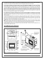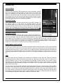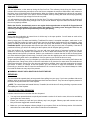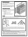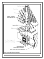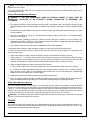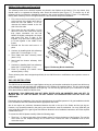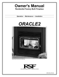
1
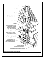
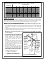
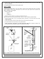
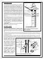
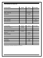
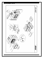
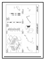
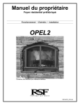
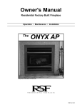
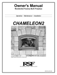
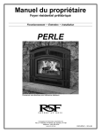
Owner's Manual Residential Factory Built Fireplace Operation • Maintenance • Installation ONYX2 Keep these instructions for future use. RSF-IIN2_2010-04 Dear Customer, The ONYX2 incorporates technology with elegance to give you a beautiful view of the fire without compromising on heating efficiency or environmental quality. We have designed your new ONYX2 to be easy to install, operate and maintain. It is in your best interest to become familiar with it. Study your manual to be sure that the installation is correct, then follow the guidelines for operation and maintenance. We at RSF Woodburning Fireplaces congratulate you on your choice of the ONYX2, and are confident that you have purchased a fireplace that is simply, the best. Sincerely, RSF Woodburning Fireplaces TEAM June 2007 TABLE OF CONTENTS SAFETY FIRST DO'S AND DONT'S CREOSOTE: FORMATION AND REMOVAL GENERAL SPECIFICATIONS THE COMBUSTION CONTROL SYSTEM OPTIONS UNIT DIMENSIONS AND CLEARANCES OPERATION AIR CONTROLS BURN TIME VS. HEAT OUTPUT FUEL FIRST FIRES LIGHTING REFUELING TROUBLESHOOTING PROBLEMS MAINTENANCE GENERAL CLEANING PAINT GLASS CLEANING CHIMNEY CLEANING DISPOSAL OF ASHES DOOR ADJUSTMENT GOLD PLATING INSTALLATION STANDOFFS INSTALLATION ONYX2 Owner's Manual 3 MOBILE HOME INSTALLATION LOCATION CEILING CLEARANCE OUTSIDE AIR DUCT CHIMNEY CHIMNEY INSTALLATION OFFSET CHIMNEY CHASE ENCLOSURE MASONRY CHIMNEY FRAMING HEARTH EXTENSION BENEATH HEARTH EXTENSION MANTEL MANDATORY OPTIONS WITH THE CLEAN FACE REFRACTORY BRICK INSTALLATION GAS LOG INSTALLATION 3 3 4 4 4 5 7 11 11 14 14 14 15 16 17 17 18 19 19 19 19 20 20 7 7 7 8 8 8 8 LISTING LABEL 22 9 COMPLETE OPTIONS LIST 23 CONFIGURED OPTIONS LIST 24 REPLACEMENT PARTS 25 LIMITED WARRANTY 27 9 9 9 9 9 10 10 10 11 2 RSF Woodburning Fireplaces SAFETY FIRST DO'S AND DONT'S If this fireplace is not properly installed, a house fire could result. For your safety, follow the installation directions. Contact your local authority having jurisdiction (such as municipal building department, fire department, fire prevention bureau, etc.) regarding restrictions and installation requirements, and the need to obtain a permit. To ANYONE using this fireplace: these DO's and DO NOTs are for your safety. 1. DO read this instruction manual before lighting your first fire. 2. DO burn seasoned wood fuel or densified fuel logs. 3. To avoid glass breakage, DO NOT slam the fireplace door. 4. DO NOT ever use gasoline, gasoline-type lantern fuel, kerosene, charcoal lighter fluid or similar liquids to start or freshen up a fire in this fireplace. Keep all such liquids well away from the fireplace while it is in use. 5. DO NOT overfire the fireplace. If you are unable to slow down the burning rate of the fire or if the chimney connector behind the top louver glows red, you are overfiring the fireplace. 6. DO operate the fireplace with the door fully closed. If the door is left partly open, gas and flame can be drawn out of the fireplace opening, creating both fire and smoke hazards. 7. DO keep all combustible materials (furniture, firewood, etc.) at least 4' away from the front of the fireplace. 8. DO NOT use a fireplace grate or other products not specified for use with this fireplace. NOTE: We strongly recommend that our products be installed and serviced by professionals who are certified by the National Fireplace Institute in the U.S. or by Wood Energy Technology Transfer Inc. in Canada. CREOSOTE: FORMATION AND REMOVAL When wood is burned slowly, it produces tar and other organic vapors which combine with the expelled moisture from the wood to form creosote. The creosote vapors can condense in the relatively cool chimney of a slow burning fire. When ignited, this creosote makes an extremely hot fire. The chimney should be inspected periodically during the heating season to see if a creosote build-up has occurred. If a significant layer of creosote has accumulated (1/4" or more), it should be removed to reduce the risk of chimney fire. WARNING: BURN DRY WOOD ONLY. DO NOT BURN: DRIFTWOOD, TREATED WOOD, COAL, GARBAGE, OR PLASTIC. Do not use construction scraps (e.g. 2x4 or plywood scraps) as your only supply of fuel as you can overheat and seriously damage the fireplace. Do not use more than one wax fuel log (e.g. Duraflame) at a time and only with a firescreen on the fireplace. Use only firelogs that have been evaluated for fireplace use. In Canada, they should meet the requirements of ULC/ORD-C127-M1990. Refer to the firelog warnings and caution markings prior to use. ONYX2 Owner's Manual 3 RSF Woodburning Fireplaces GENERAL SPECIFICATIONS The ONYX2 fireplace is environmentally friendly as well as efficient. It is approved by the United States Environmental Agency (EPA) at an emission rate of 4.5 grams per hour. THE COMBUSTION CONTROL SYSTEM Since the door is sealed, all combustion air must come through the ONYX2's draft control. This control has a bimetal coil to allow more air when the unit is cold, and less air when the unit is hot, guarding against overheating. It can be controlled either manually with the lever that is located on the right below the door, or automatically with an optional electric wall thermostat. For the first few days, it is best to operate the fireplace with the manual control fully open (moved to the right as far as possible). Just control the fire as you would any normal fireplace, using one or two logs at a time for a smaller fire, or more logs for more heat. Once you become familiar with operating the fireplace with the control open, you can start experimenting with lower settings. Remember: when the fireplace is hot, the control will not need as much movement to reduce the fire as when it is cold. The bimetal coil will already have shut the damper part way. OPTIONS There are many different ways you can finish your ONYX21 fireplace. You can choose to install louvers, they are available in various colors (regular black: FO-ONLB, regular gold: FO-ONLG, regular pewter: FO-ONLP or classic black: FO-ONLC) or no louvers at all (FO-F2). If you choose to install your ONYX2 fireplace without any louvers, you MUST install the Clean Face Option (FOF2) along with two Gravity Vent Kits (FO-V2). Gravity vent dampers CANNOT be installed on a Clean Face ONYX2. Furthermore, we recommend that you do not install any option requiring electricity or a thermal switch inside your fireplace since it will be difficult to access those components after the fireplace facing is covered with non-combustible materials. If you decide nevertheless to install electricity or a thermal switch in your Clean Face ONYX2, remember that you may eventually have to break through the non-combustible finishing to access the electrical box or the thermal switch for servicing. To simplify the installation of thin non-combustible materials such as ceramic tile or sliced brick, we have designed a rock retainer kit. It is not designed or required for full brick or stone. With a Louvered ONYX2, you can choose to leave all the black metal completely exposed or completely covered with non-combustible material. Whether you have chosen a Louvered or Clean Face ONYX2, the FO-KN kit will help you finish the facing of the fireplace as you wish. Thin materials can also be installed directly on the face of the ONYX2 using high temperature silicone as glue, without a rock retainer kit. For increased air circulation and marginally more heat output, you can add the Circulating Internal Blower (FOFDHB5-N) to your Louvered ONYX2 or the Inline Fan (FO-CIF) to your Clean Face ONYX2. NOTE: The Onyx2 is equipped with a floor shield to protect the floor under the fireplace. This floor shield is made of two parts: the front part is insulated; the back part is a simple part. Both parts are screwed together and factory installed to cover the entire floor below the firebox. It must never be removed. Only when installing the Internal Blower Option, the floor shield must be modified. Follow the internal blower installation instructions but before reinstalling the floor shield, remove the screw, slide the back part over the front part and screw them back together. If you ever remove the internal blower make sure to extend the shield again. If you have any rooms directly above or adjacent to the room with the fireplace that you would like to heat, you may want to consider the Gravity Vent Kit2 (FO-V2). The gravity vent distributes hot air to these rooms and requires no blower to assist its operation. With a Louvered ONYX2, you could also consider installing Dampers (FO-D) on your gravity vents. The dampers will enable you to choose between sending the heated air to the gravity vent outlet or keeping it in the fireplace room. For constant heat, day and night on a Louvered ONYX2, you will be surprised by what the Thermostat Option (FO-FDHC4) can do for you. This option provides you with the necessary parts to automatically control the draft control via a wall thermostat. It will keep your room temperature as even as though you were heating with oil, gas or electricity, except you will find wood heat more comfortable. Do not install this Thermostat Option (FO-FDHC4) 1 You can also refer to the configured option list on page 24. Not allowed in a mobile home installation. ONYX2 Owner's Manual 2 4 RSF Woodburning Fireplaces on a Clean Face ONYX2 because of the reduce air circulation below the firebox; the motor used in the option is not meant to work under such high temperature and this will greatly reduce the motor life span. To maximize the distribution of the heat generated by your ONYX2 fireplace throughout many rooms and different floors, consider the Central Heat Option2. With our Central Heat Blower (FO-FDHB6-1), you can use the house central heating ducts or dedicated ducts to circulate the fireplace heat to one or many rooms. The Central Heat Control (FO-FDHC6) will enable automatic control of the Central Heat Blower via a wall thermostat and thermal switch. The Zone Heat Control (FO-FDHCZ1) along with Zone Damper Kits (FO-FDHCZ2) will provide the same features as the Central Heat Control but for more than one heating zone. If you wish to install the Central Heat Blower on a Clean Face ONYX2, you will need the Central Heat T (FO-T) that will enable you to connect the central heat duct along with the left gravity vent on the fireplace. For a simpler way to circulate a moderate amount of warm air from the fireplace to another room, we offer the Heat Dump Kit (FO-HD) which uses a smaller fan than the Central Heat Blower. It is most often used to provide supplemental heating to a basement room when the fireplace is on the main floor but it can also be used to send warm air upstairs. To remove accumulated ashes from the firebox, simply shovel them into a metal container. If you have chosen to install a Louvered ONYX2, you may find the optional Ash Pan Kit (FO-CAP) very convenient. You remove the plug from the firebox and sweep the ashes into a hole to the ash pan. When the ash pan is full, simply remove the ash pan by the bottom louver and dispose of the ashes properly. NOTE: Many options require wiring and/or electricity for their installation. If there is any chance that any of these options will be installed in the future then suitable wiring should be run during framing. Otherwise, it will be difficult to install these options later. You can refer to page 23 for a list of options that require electricity. Detailed installation instructions are included in the box with each option. These can also be obtained from our Internet Web Site: www.icc-rsf.com. UNIT DIMENSIONS AND CLEARANCES 1312" 43" 1312" 8" 4" Refer to Table 1 (J) for maximum mantel depth 24" Refer to Table 1 (K) for minimum mantel height above the door opening 42" 47" 41 4" 6" 51 4" Refer to Table 1 (B) for minimum distance of side wall to the fireplace 39" 1812" 173 4" 51 4" 4" 293 4" Refer to Table 1 (H) for minimum width of hearth extension Non-combustible hearth extension and spark guard () (refer to Table1 (I) and text for particulars) Refer to Table 1 (G) for minimum depth of hearth extension Figure 1 Unit Dimensions and Clearances ONYX2 Owner's Manual 5 RSF Woodburning Fireplaces Table 1 Unit Dimensions and Clearances A Distance of combustible material from side, back and top standoffs 0" (0,0 mm) B Minimum distance of side wall to the side of the firebox opening, this does not allow to fully open the door. To be able to fully open the door without any interference from the side wall, it has to be push back at least an additional 7" 12" (305 mm) C Ceiling clearance: from the base of the fireplace to the ceiling sealed enclosure vented enclosure 7' 6' (2,13 m) (1,83 m) D Minimum chimney height: minimum total chimney height from fireplace top to below the chimney rain cap 12' (3,66 m) E Maximum chimney height: maximum total chimney height from fireplace top to below the chimney rain cap 40' (12,19 m) F Maximum chimney height supported by the fireplace 18' (5,49 m) G Minimum depth of non-combustible hearth extension: from the front of the fireplace 20" (508 mm) H Minimum width of non-combustible hearth extension: from sides of the firebox opening 9 ¼" (235 mm) I Minimum width of the spark guard 36" (914 mm) J Maximum mantel depth (see Table 2 for other mantel sizes) 12" (305 mm) K Minimum height of a combustible mantel above the top of the firebox opening: from the highest point of the top of the firebox opening to below the combustible mantel (see Table 2 for other installation heights) (refer to the "Installation: Mantel" section for particulars) 26" (660 mm) Table 2 Various Mantel Depths and Corresponding Installation Heights Maximum Mantel Depth Minimum Installation Height 0" to 6" 17" 8" 20" 10" 23" 12" 26" No combustible mantel can be installed lower than 17" above the top of the firebox. A combustible mantel cannot be wider than 12". For combustible mantel depths not mentioned in the list above, you can interpolate the minimum installation height between the two closest mantel depths. For example: • Mantel depth to be installed: 9 ¼" • It is between 8" and 10" with corresponding installation heights of 20" and 23" • So: ((9.25 – 8) / (10-8) x (23-20))+20 = 21.875 = 21 7/8" • Minimum installation height of a 9 ¼" mantel: 21 7/8" above the firebox opening If the combustible mantel has a cross-section with variable depth, it has to be installed so that its widest part is not installed lower than the corresponding minimum installation height while making sure that the lowest point of the mantel is not installed lower the minimum installation height corresponding to it depth. Refer to the "Installation: Mantel" section for particulars. ONYX2 Owner's Manual 6 RSF Woodburning Fireplaces OPERATION AIR CONTROLS Unlike most open fireplaces, RSF fireplaces don’t have flue dampers. Instead, the system is sealed by closing the door, and the amount of air entering the firebox is controlled by the combustion air control lever on the front of the fireplace on the right below the door (see Figure 2) which can be moved left or right. Setting the air control lever all the way open (towards the right) will allow the maximum amount of air into the firebox. Closing the air control (towards the left) will reduce the amount of air entering the firebox. Bi-metallic Damper The bi-metallic damper is a unique feature built into your OPEL2 fireplace. As the fireplace heats up it will activate the bi-metallic damper. This will automatically begin to shut down the air entering the firebox, slowing the combustion process. This will save you wood in the long run, and prevent the fireplace from overheating and causing potential damage to the firebox. We suggest that the combustion air control lever is used as the primary control to limit the oxygen entering the firebox, and that the bi-metallic damper is left as an additional safety system. Towards the left to CLOSE Towards the right to OPEN Outside Air Control The ONYX2 has been designed to offer you the choice to use outside air or Figure 2 Air Control inside air for combustion. You will find a sliding door behind the bottom louver and below the firebox. Push the sliding door towards the back to select outside air or pull it toward the front to select inside air as the combustion air. Because outside air is generally colder and denser it will help to start the fire. In some cases this fresh air will also help compensate for negative pressure problems within the house; however it will not prevent the fireplace from smoking in a severely depressurized house. If the fireplace is installed in a mobile home, the outside air has to be used as combustion air. BURN TIME VS. HEAT OUTPUT The faster your fireplace burns the more heat it will create; however, faster fires result in much more hot air flow up the chimney which means you are sacrificing efficiency. Fast burning fires (lots of air) go through much more wood than slow burning fires. To get the most out of your ONYX2 fireplace, adequately adjust the combustion air control lever at the appropriate time. If the fire seems to be burning too quickly, turn the air down. If the fire is smoldering and there are no visible flames, turn the air up. This way you’ll always be getting the most out of your fuel. FUEL All modern high efficiency fireplaces and woodstoves are designed to burn best with seasoned cordwood. Seasoned wood can be defined as wood that has been cut, split and let dry under cover for a minimum of 6 months, preferably a year or more. Dry seasoned wood generally contains less than 20% moisture content. Attempting to burn fuel with a high moisture content will be difficult and result in lower efficiency, increased creosote buildup and dark deposits on the glass. It’s possible to burn a very large amount of wood, and get very little heat if the wood is wet. The type of wood you select is also important. All types of wood give off more or less the same number of BTU’s per pound. Since softer woods are less dense than hardwoods it is possible to put more weight of hardwood in the firebox; in other words all woodburning appliances will burn longer and more evenly with hardwoods. Never burn scrap, garbage, treated wood or driftwood as they produce much more pollution and can corrode the firebox and chimney as well. Burning large amounts of paper, cardboard, mill ends or construction waste can easily over fire and damage the fireplace or even ignite a chimney fire if the flue is dirty. ONYX2 Owner's Manual 7 RSF Woodburning Fireplaces FIRST FIRES You will experience a slow start-up during the first few fires. The refractory bricks lining the firebox contain moisture from manufacturing and require a few hot fires to evaporate the moisture. While there is still moisture in the bricks, they will be black with smoke deposits. When the moisture has dissipated, the bricks will turn white. Unlike cast iron stoves, there is no need to cure the fireplace itself by starting with small fires and progressively larger ones. Feel free to light a large fire from the very start. You will experience a slight odor during the first few fires. This odor comes from curing paint and oil burning off the metal. The odor may be strong enough to set off your smoke detector. Open the doors and windows to allow the room to properly ventilate. Before the first fire, be absolutely sure to use regular dish soap and water to wipe off all fingerprints and debris from the gold plating if you have chosen this option. The plating cures during this first fire, the acid from your finger prints will permanently etch the gold plating. LIGHTING Ensure that the combustion air control lever is all the way in the open position. You will want as much air as possible for the lighting process. Start by laying your fire starter and kindling. Traditional fire starter is crumpled newspaper; make sure to use enough to light the kindling (5-6 pieces should do). Next lay the kindling crisscrossed over the newspaper. Using plenty of kindling ensures that the chimney will heat up quickly and establish a strong draft, never use any flammable liquids. Light the paper and close the door most of the way, but don’t shut it completely. If the door is positioned correctly you will see air rushing into the fireplace, this will help the lighting process. Once the kindling is lit and sustaining fire, you can add some small pieces of seasoned cordwood. Use the andirons in front to help position the cordwood so as not to flatten and smother the fire you’ve just created. Always add at least 3 pieces of cordwood. Position your cordwood in a manner that the fire will hit several pieces as it rises and has air gaps to flow through. Continue to leave the door slightly open until the cordwood is lit. Close the door completely when the fire is established, if the fire goes out you’ve shut the door too early. To get maximum efficiency out of your fireplace you will want to adjust the amount of air entering the firebox at the appropriate times. Gauge how much to close the combustion air by how the fire reacts once the combustion air control lever has been moved. If the fire goes out and begins to smolder, there’s too little combustion air entering the firebox. If there’s no change to the burn pattern, you can continue to close the combustion air further. Eventually you should be able to close the combustion air all or most of the way. There should always be visible fire inside the firebox at every step of the process. WARNING: DO NOT USE A GRATE OR ELEVATE THE FIRE. REFUELING The door should be opened slowly to keep smoke from spilling into your room. If you have a problem with smoke spillage, check to see that all kitchen and bathroom fans have been shut off. They can cause negative pressure in the house which pulls smoke out of the fireplace. NOTE: The central heat and internal blowers, if installed, should be shut off during refuelling to prevent smoke from spilling out of the fireplace. TROUBLESHOOTING PROBLEMS If smoke comes into the house when the door is opened: • You may have opened the door too quickly and created a suction of air into the room, this can be avoided by opening the door more slowly. • Ensure your chimney is clean and your chimney cap is not plugged. Chimney caps with screens are more likely to become clogged with creosote buildup. • Make sure you have adequate chimney height for your system. Refer to the Chimney section of this booklet and make sure to take altitude, and number of elbows into consideration. ONYX2 Owner's Manual 8 RSF Woodburning Fireplaces • If you have purchased the central heat kit option or the circulating internal blower, make sure the blower is off before opening the door. • Check to see if other fans in the home are running, particularly a kitchen range hood, or bathroom exhaust fan. This can affect the pressure in the home. • Try opening a window near the fireplace a little, this will equalize the pressure in the home and should correct a draft problem. Once proper draft is established the window can be closed. • Make sure you’ve used enough kindling to establish a hot fire quickly. The most likely time that smoke will enter the home is during the lighting process. MAINTENANCE GENERAL CLEANING The high heat paint and plating can be cleaned with a soft damp cloth. Use a mild detergent and water. Do not use abrasive cleaners. PAINT You can touch up the face of the ONYX2 with Stove Bright Metallic Black high temperature paint which is available at most fireplaces dealers. Follow the directions outlined on the spray can. DO NOT attempt to paint the fireplace while it is still warm. Keep the spray can away from any source of heat or open flame. Ensure that there is adequate ventilation in the room from the time you start painting until the paint is dry. Stove Bright is available in a wide range of colors if you want to change the color of your ONYX2. We recommend that you take the time to protect or remove any item that you do not want to paint such as: the door glass, the plated door, the fireplace surroundings, etc. The glass can be removed from the door but you will have to replace the window gasket. GLASS CLEANING In a controlled combustion firebox, temperatures are not always high enough to keep the glass perfectly clean. A good hot fire once a day usually cleans off most of the deposits that have accumulated. Remember: the drier the wood and the hotter the fire, the cleaner the glass. A word of caution: although heat will not break the glass, impact can. Be careful not to hit the glass. WARNING: NEVER CLEAN THE GLASS WITH AN ABRASIVE CLEANER. USE ONLY A CLEANER RECOMMENDED BY YOUR DEALER. NEVER CLEAN THE GLASS WHILE IT IS HOT, A SERIOUS BURN CAN RESULT. THERE ARE A NUMBER OF EXCELLENT WOOD STOVE GLASS CLEANERS AVAILABLE WHICH ARE FAR SUPERIOR TO REGULAR GLASS AND OVEN CLEANERS FOR WOOD STOVE APPLICATIONS. CHIMNEY CLEANING Check the chimney for creosote buildup every week or so until experience shows how often you need to clean it. A buildup of ¼" or more should be cleaned before more creosote accumulates. Use an 7" round brush. The baffle in the firebox can be removed to gain access to the flue from below. Follow the directions in the Refractory Brick Installation section to remove and replace the baffle. If you prefer, you can simply lift the baffle and move it forward and let the debris fall in the firebox. Do not forget to push the baffle back in its place after cleaning the chimney. This second option is easier than removing the baffle. DISPOSAL OF ASHES Remove the ashes before they become too deep, i.e., before you have a spillage problem when you open the door. The ashes should be placed in a metal container with a tight-fitting lid. The closed container of ashes should be placed on a non-combustible floor or on the ground, well away from all combustible materials pending final ONYX2 Owner's Manual 9 RSF Woodburning Fireplaces disposal. If the ashes are disposed of by burial, or otherwise locally dispersed, they should be retained in the closed container until all cinders have thoroughly cooled. DOOR ADJUSTMENT The door hinge can be adjusted for proper sealing of the left side of the door. Since the door latch is progressive, the more your turn the handle the tighter the seal on the right side of the door. Beware not to always over tighten the door latch; this will result in premature failure of the door gasket. To check for a proper door seal, insert a thin sheet of paper between the door and the front of the fireplace and latch the door. Pull gently but firmly on the sheet of paper. If the paper either tears or is hard to retrieve, the adjustment is correct. Repeat this procedure along all sides of the door. The most important factor for controlling the burning rate of the ONYX2 is a good seal on the door gasket. If the door gasket is worn or damaged to the point where the seal is not adequate as described above, then remove and replace the gasket. Replacement kits are available from your RSF dealer. To insure a proper seal, you need to adjust the tightness of the door against the front of the fireplace as follows: 1. To tighten the left side of the door, slightly loosen the screws holding the hinge to the door (see Figure 3). 2. With the door open, push the door towards the facing of the fireplace so as to move the hinge towards the center of the door. This will move the door slightly closer to the facing of the fireplace when it is closed. Figure 3 Hinge Adjustment on the Door 3. Continue by retightening all the hinge screws on the door. 4. Verify the alignment of the door with the firebox opening and the latch opening. 5. If necessary, slightly loosen the screws holding the hinge to the fireplace facing (see Figure 4). Move the door with the hinge as desired. Retighten all the hinge screws on the fireplace. 6. Verify the seal with the sheet of paper as described above. NOTE: An improperly adjusted door seal can have a significant effect on the performance and durability of the fireplace. A poorly adjusted door can result in reduced efficiency, over firing, excessive wood consumption and premature fireplace failure. GOLD PLATING If you have gold louvers, you will be happy to know that they will not tarnish. However, they are not scratch resistant. Use only mild soap and warm water to clean the gold when the surface is cool. The use of any household cleaner, such as Windex, abrasive cleaners, or any form of acid, may permanently etch or remove some of the gold plating. Before the first fire, make sure to clean all fingerprints and other deposits on the gold plating. Since the plating cures during the first fire, fingerprints and other deposits will permanently etch the gold plating. Figure 4 Hinge Adjustment on the Fireplace INSTALLATION Check with your local authority having jurisdiction (such as municipal building department, fire department, fire prevention bureau, etc.) regarding restrictions and installation requirements, and the need to obtain a permit. Make sure to adequately protect the door to prevent any damage to it until the installation and finishing work is finished. Be aware that heavy duty cleaning products or acid solutions will permanently damage the plating. ONYX2 Owner's Manual 10 RSF Woodburning Fireplaces STANDOFFS INSTALLATION Before you begin installing you fireplace, you MUST install the standoffs provided on both sides of the fireplace and on the top. Please refer to Figure 5 to position them adequately. Once the standoffs are in place, make sure to seal the ¼" gap between the fireplace and the standoffs with a high temperature sealant. DO NOT fill the gap behind the sealant with insulation or any other material. MOBILE HOME INSTALLATION The installation of your ONYX2 fireplace is the same whether you install it in a regular home or in a mobile home. Nevertheless, you MUST comply with the following restrictions: 1. You MUST use a vented roof flashing. 2. You CANNOT install gravity vents. 3. You CANNOT install the central heating system. 4. You MUST use outside air as combustion air. Figure 5 Standoffs Installation LOCATION Your ONYX2 fireplace may be installed in many different ways (see Figure 6) without any special floor reinforcement. We recommend that you take the time to plan your entire installation (fireplace, chimney, and options) before beginning the actual installation (refer to Figure 7 and Figure 8). 22" 64" 44 1/4" 45" 45" 24" 90" The framing dimensions are larger than required for ease of installation. Examples shown here are for a Louvered ONYX2. An extra 12" is required on the left of the fireplace of a Clean Face ONYX2 to connect the intake air duct. The Heat Dump Option will also require an extra 12" on the selected side. Additional space, dependant on your desired installation, is also required on top and maybe on one side of the fireplace for the Central Heat Option Figure 6 ONYX2 Framing Examples Dimensions of the fireplace along with clearances are shown in Figure 1 and Table 1. WARNING: IF THIS FIREPLACE IS NOT PROPERLY INSTALLED, A HOUSE FIRE CAN RESULT. FOR YOUR SAFETY, FOLLOW THE INSTALLATION INSTRUCTIONS AND CLEARANCES. DO NOT PACK REQUIRED AIR SPACES WITH INSULATION OR OTHER MATERIALS. ONYX2 Owner's Manual 11 RSF Woodburning Fireplaces Rain Cap Storm Collar Flashing Radiation Shield with a Storm Collar in the Attic Radiation Shield Ceiling Hearth Extension and Beneath Hearth Extension (refer to text for particulars) Electrical Knock-outs (on both sides of the fireplace) Outside Air Inlet (refer to text for particulars) Figure 7 Louvered ONYX2 General Installation ONYX2 Owner's Manual 12 RSF Woodburning Fireplaces Rain Cap Storm Collar Flashing Radiation Shield with a Storm Collar in the Attic Radiation Shield Ceiling Gravity Vent Option FO-V2 (using flexible insulated ducting provided by ICC only): Two FO-V2's are MANDATORY with Clean Facing (shown here) Intake Grill part of Clean Facing Option FO-F2 Obstruction plates part of Clean Facing Option FO-F2 Hearth Extension and Beneath Hearth Extension (refer to text for particulars) Electrical Knock-outs (on both sides of the fireplace) Outside Air Inlet (refer to text for particulars) Figure 8 Clean Face ONYX2 General Installation ONYX2 Owner's Manual 13 RSF Woodburning Fireplaces 1. Note the location of roof and floor joists. Try to choose a location that does not require cutting them. 2. If at all possible, run the chimney up through the inside of the house. If it must be run outside, it should be enclosed in an insulated enclosure (see Installation: Chase Enclosure). Remember, a cold chimney causes poor draft. CEILING CLEARANCE Ceiling clearance is the distance from the base of the fireplace to the ceiling. If you vent the fireplace enclosure, you can then have a lower ceiling clearance as specified in Table 1 (C) for a vented enclosure. For a vented enclosure, you MUST install regular venting 3"x10" grilles or larger into holes cut within 1' of both the floor and the ceiling, to allow room air to circulate through the fireplace enclosure and reduce heat buildup. These venting grilles may be placed vertically or horizontally. Under no circumstances should the distance between the ceiling firestop and the base fireplace be less than the dimension specified in Table 1 (C). OUTSIDE AIR DUCT Below Floor Example Above Floor Example Use an insulated aluminium flexible duct rated at over 200° F. The duct should not exceed 12' vertical rise above the base of the unit. Fi R S re F pl ac e Fi RS re F pl ac e After the fireplace is correctly positioned, connect the outside air inlet to the outside (see Figure 9). The air inlet should never be less than 5' below the top of the chimney flue and must never terminate in attic spaces. 2" Aluminium Duct Tape Outside Air Inlet Fi RS re F pl ac e A 4" diameter duct can be used if the total duct run is less than 25'. For longer runs, use 5" diameter duct. Both 4" and 5" connecting sleeves are provided with the fireplace. 1. Find a convenient location for the combustion air duct and outside air inlet. The outside air inlet can be above or below floor level. Insulated Flexible Air Duct Outside Wall 2. Make a 4 ¼" (5 ¼" if using a 5" diameter duct) hole in the outside wall of the house. Push the outside air inlet in from the outside. Seal the joint between the air inlet and the outside wall with an appropriate sealant. Figure 9 Outside Air Connection and Installation Example 3. Place the insulated flexible duct over the round sleeve on the outside air inlet. At both ends, carefully pull back the insulation and plastic cover, exposing the flexible duct. Then at each end, attach the duct with metal screws to the air inlet and to the fireplace connecting sleeve. Carefully push the insulation and cover back over the duct. Tape the plastic cover in place with 2" aluminium duct tape. CAUTION: WHEN RUNNING THE DUCT AROUND CORNERS, BE SURE TO PREVENT CRIMPING THE DUCT THAT WOULD RESTRICT THE COMBUSTION AIRFLOW. CHIMNEY This fireplace is certified for use with 7" ICC Model EXCEL chimney only. Please refer to Table 1 (D-E) for the minimum and maximum chimney height permitted with the ONYX2 fireplace. We recommend that the minimum height be increased by approximately 1' for every 2000' elevation above sea level. Every 30° or 45° elbow also increases the minimum height by 1'. For example, if you are living 6000' above sea level, your chimney should terminate at least 15' from the top of the fireplace (12' + 3' for the 6000'). See Table 3 for more precise recommended flue heights. ONYX2 Owner's Manual 14 RSF Woodburning Fireplaces Table 3 Minimum Recommended Flue Heights In Feet From The Top Of The Fireplace Number Of Elbows Elevation (ft) 0 - 1000 1000 - 2000 2000 - 3000 3000 - 4000 4000 - 5000 5000 - 6000 6000 - 7000 7000 - 8000 8000 - 9000 9000 - 10000 0 12’ 12’6” 13’ 13’6” 14’ 14’6” 15’ 15’6” 16’ 16’6” 2 x 15° 13’ 13’6” 14’ 14’6” 15’ 15’6” 16’ 16’6” 17’ 17’6” 4 x 15° 14’ 14’6” 15’ 15’6” 16’ 17’ 17’6” 18’ 18’6” 19’ 2 x 30° 15’ 15’6” 16’ 17’ 17’6” 18’ 18’6” 19’ 20’ 20’6” 4 x 30° 18’ 19’ 19’6” 20’ 21’ 21’6” 22’ 23’ 24’ 24’6” 2 x 45° 16’ 16’6” 17’ 18’ 18’6” 19’ 20’ 20’6” 21’ 22’ 4 x 45° 20’ 20’ 21’6” 22’6” 23’ 24’ 24’6” 25’6” 26’6” 27’ CHIMNEY INSTALLATION Make sure to read the EXCEL Chimney installation manual concerning requirements for supports, bracing, anchors, etc. The EXCEL Chimney manual is available at your RSF dealer or on our web site: www.icc-rsf.com. Refer to Table 1 (F) for the maximum chimney height that can be supported by the top of the fireplace. WARNING: THE CLEARANCE BETWEEN THE CHIMNEY AND COMBUSTIBLE MATERIAL MUST BE 2" OR MORE. DO NOT FILL THIS AREA WITH INSULATION. 1. Cut and frame the required holes in the floor(s), ceiling(s) and roof where the chimney will pass through. The rough opening in the framing is 13" square (the opening can be slightly bigger, up to 13 ½", but NEVER smaller). 2. From below, install a radiation shield in each floor through which the chimney passes. At the attic level, install a radiation shield and a storm collar as shown in Figure 10. WARNING: A RADIATION SHIELD MUST BE INSTALLED AT EACH FLOOR WHERE THE CHIMNEY PASSES THROUGH. Rain Cap 3. Remove the flue adapter from the fireplace, put the screws aside. Install the flue adapter on the first chimney length and secure it with the screws provided. Reinstall the flue adapter on the fireplace and secure it with the screws you have put aside earlier. Assemble the rest of the chimney. 2' min. 10' WARNING: DO NOT PACK REQUIRED AIR SPACES WITH INSULATION OR OTHER MATERIALS The chimney must extend at least 3' above its point of contact with the roof and at least 2' higher than any wall, roof, or building within 10' of it. If the chimney is higher than 5' above the roof, it must be secured using a roof brace. • In Canada: use a vented flashing, or a roof radiation shield with a regular flashing. Storm Collar in the Attic 2" min. WARNING: must be framed to adequately support any chimney supports and roof assemblies Radiation Shield The chimney must be enclosed when it passes through living spaces: min. clearance of 2" with chimney If the chimney is enclosed to the roof: In USA: use a vented flashing; 3' min. NOTE: Openings 4. Put the roof flashing into place. Seal the joint between the roof and the flashing with roofing tar. For sloping roofs, place the flashing under the upper shingles and on top of the lower shingles. Nail the flashing to the roof using roofing nails. • Flashing with Storm Collar F e RS plac re Fi MAJOR RISK OF FIRE, LOOSE FILL INSULATION MUST NOT GO ABOVE THE RADIATION SHIELD AND MUST NEVER COME IN CONTACT WITH THE CHIMNEY Ceiling Clearance (see Table 1 (C)) Figure 10 General Chimney Installation ONYX2 Owner's Manual 15 RSF Woodburning Fireplaces 5. Place the storm collar over the chimney and flashing. Seal it around the chimney with silicone sealer (DO NOT use roofing tar). 6. Fit the rain cap on the chimney. Secure it tightly in place. OFFSET CHIMNEY An elbow may be installed directly on top of the fireplace if required. See the detailed offset charts in the EXCEL chimney installation manual. Use the offset option if you need to clear a joist or pass around a cupboard. See Figure 11 and Figure 12 for examples. • • Maximum offset angle: • In USA: 30°; • In Canada: 45°. Maximum number of elbows: four, resulting in two offsets and returns. Install the fireplace and chimney as described earlier. When you require an elbow, proceed as follows: 1. Install the required elbow. Turn it in the desired direction, and fasten it to the other section with 3 metal screws at the joints. 2. Install enough lengths to obtain the desired offset. Secure each joint with 3 metal screws. 3. Use another elbow to return the chimney to the vertical direction. 4. Install a roof support, a wall support, or an offset support above each offset to support the weight of the chimney (elbows are not designed to support the chimney above an offset). Radiation Shield 2' min. 1' min. 10' Flashing* with Storm Collar & Roof Radiation Shield Rise Use Offset Support or Roof Support Offset Radiation Shield and Offset, Roof or Wall Support Radiation Shield *In USA: use a vented flashing 3 Metal Screws in Each Joint Fi R S re F pl ac e *In Canada: use a vented flashing or a roof radiation shield with a regular flashing SF ce R p la re Fi Figure 11 Offset Chimney Installation Example ONYX2 Owner's Manual Insulated Wall Radiation Shield (30° or 45°) Figure 12 Offset Chimney Through a Wall Example 16 RSF Woodburning Fireplaces CHASE ENCLOSURE If the chimney runs up the outside of the house, we recommend that it be enclosed in a chase structure. The chase should be constructed in such a way that it is an extension of the home (see Figure 13). It should be well insulated between the footings and the floor of the home to prevent heat loss. If the climate in your area is mild, insulate the chase at least to the first firestop. If the climate in your area is very cold, insulate the chase to the top to keep the chimney warmer, increase the draft, and reduce creosote buildup. We also recommend to insulate the ceiling of the chase just as if it were in the attic space. This will prevent cold air from dropping down through the chase and into the room where the fireplace is installed (see Figure 13). 2' min. 10' Optional Decorative Shroud Insulation Chase liner of fire rated gypsum board is recommended (may be required by local authorities) Radiation Shield, with Storm Collar in the Attic F i RS re F pl ac e Some local codes require that the walls be insulated, vapor sealed and sheathed with a fire rated gypsum board (see Figure 13). We strongly recommend this procedure for all installations to prevent cold drafts from originating in the fireplace enclosure. If you follow this procedure, we recommend that you do not insulate the wall above the front of the fireplace. REMEMBER: Check local codes concerning installation requirements and restrictions in your area. MASONRY CHIMNEY Installing your ONYX2 fireplace with a masonry chimney still requires using EXCEL chimney from the top of the fireplace to the wall where it will connect to a listed liner that will run up inside the masonry chimney (see Figure 14). Figure 13 Chimney Installed with a Chase Enclosure Example The stainless steel liner should be fitted inside the clay liner all the way to the top of the masonry chimney. It is not meant to replace the clay liner. You can use either the EXCEL liner or any other listed liner to ULC-S635, ULC-S640 or UL-1777. Special care is to be taken to make sure that you have a good solid connection between the EXCEL chimney and the liner. A masonry adaptor (FO-FDM7) was designed specifically for that purpose and is available from your RSF dealer. It will attach to the EXCEL liner or other listed liner to Clearances as per liner with 3 stainless steel rivets ULC-S635, ULC-S640 or UL-1777 NBC or NFPA 211 (provided) and to the EXCEL chimney with 3 screws (provided). As depicted in Figure 14, you must install at least one 18" length of EXCEL chimney after the EXCEL chimney elbow. The uppermost part of the EXCEL chimney - where it enters the masonry chimney - must be a minimum of 12" from the ceiling. Metal Firestop 12" min. to combustible ceiling Mortar EXCEL chimney lenght: 18" min. Liner Elbow EXCEL chimney elbow Mortar Fi RS re F pl ac e After mortaring in place, the connection between the EXCEL chimney and the liner should not be visible in order to isolate the heat released through the liner from the fireplace enclosure. Masonry Adaptor FO-FDM7 Figure 14 Connection to a Masonry Chimney ONYX2 Owner's Manual 17 RSF Woodburning Fireplaces NOTE: If the ceiling is high enough, you can install one or more EXCEL chimney lengths directly on the fireplace before the elbow. If you use a flexible liner, make sure to be careful when cleaning to ensure that the stainless steel flexible liner is not dislodged in any way. Using an Existing Masonry Chimney WARNING: IF YOU ARE CONSIDERING USING AN EXISTING CHIMNEY, IT MUST FIRST BE THOROUGHLY INSPECTED BY AN AUTHORITY HAVING JURISDICTION TO DETERMINE THE FOLLOWING: 1. The masonry chimney is well constructed and fully lined, in accordance with Local Building Codes and the National Building Code of Canada (NBC) or National Fire Protection Association chimney standard (NFPA 211). 2. It has been thoroughly cleaned of any soot or creosote residue and inspected to determine that it is in good working condition. 3. There is no insulation of any type in contact with the masonry chimney and there is no insulation stuffed anywhere in the chimney. 4. All the necessary clearances around the masonry chimney, along the complete run of the chimney, are respected as per NBC or NFPA 211. If the masonry chimney is enclosed in drywall, openings will probably be required in order to verify clearances at all points. 5. The masonry chimney will only be used for the fireplace and no other appliance. If major repairs are required to meet the above conditions, a new chimney should be constructed. To make the hole through the masonry chimney and make the connection to the fireplace, we recommend that you follow these steps: 1. Sight-in and mark the outline of where the EXCEL chimney will penetrate the masonry chimney. 2. Using a large (¾" - 2") masonry drill bit, drill a hole exactly in the center of the oval outline. With a masonry hammer and drill, slowly enlarge the hole to the size required. Remember to work from the center out. Be especially careful with the clay liner behind the brick because three sides of it must stay in place. 3. Bring the stainless steel liner down from the top of the chimney. If you are using a rigid liner you will need enough room to secure an elbow to it with at least two screws. If it is difficult to install rigid stainless steel liner in the existing masonry chimney or for a masonry chimney with less than 10"x10" inside, a listed stainless steel flexible liner can be used along with a flexible/rigid adaptor (LM-7LAF) available from your RSF dealer. 4. Install the liner elbow and masonry adaptor on the lower end of the liner. 5. Move the fireplace forward enough to install the EXCEL chimney on the fireplace (elbow and length) then move the fireplace back into position as you connect the masonry adaptor to the EXCEL chimney. Using a New Masonry chimney Since the masonry chimney is not build yet, we recommend that you position your fireplace, install the EXCEL chimney on it and connect to the first length of liner before building the chimney as explained above and shown in Figure 14 . The liner sections can easily be installed as the layers of brick are being placed. Since this is a new chimney, we recommend that you build it to the right size so you do not have to ovalize the liner but if you choose to use a 6"x10" clay liner you will need to ovalize the stainless steel liner to fit into the clay liner. Remember: The stainless steel liner should be fitted inside the clay liner all the way to the top of the masonry chimney. It is not meant to replace the clay liner. FRAMING The enclosure walls can be framed with any suitable materials (2x4 or 2x6 studs, plywood, gypsum board, etc.). Because of the high heat output potential of the ONYX2, combustible materials must NOT go closer to the fireplace than the standoffs, top, back and sides. ONYX2 Owner's Manual 18 RSF Woodburning Fireplaces You may also completely cover the top of an ONYX2 as long as you maintain all fireplace standoff clearances and the 2" clearances around the chased chimney. The 2" clearance around the chimney must be open from the fireplace up to the ceiling. See Figure 15 for an example of a close clearance installation. Always maintain 2" min. clearance with chimney Leave the space between the chimney and the framing open (no firestop) HEARTH EXTENSION Always respect the fireplace standoffs The area immediately in front of the fireplace must be protected by a non-combustible material such as brick, tile, stone, or slate. Refer to Table 1 (G-H) for the depth and width that the hearth protection should extend beyond the front and both sides of the door opening (see Figure 1). There is no minimum thickness required for the hearth extension. Figure 15 Close Clearance Installation of an ONYX2 BENEATH HEARTH EXTENSION If the ONYX2 is installed on a non-combustible floor, the spark guard specified below is not required. RSF Fireplace Install the spark guard provided (5" x 36" piece of sheet metal) halfway under the fireplace and halfway under the hearth extension and centered on the door opening. The spark guard will extend 2½" beneath the fireplace. This will make certain that sparks cannot lodge in this area and start a fire. If necessary, the provided spark guard can be cut to the minimum width specified in Table 1 (I). NonCombustible Flooring Right Angle Spark Guard (not provided) 2 1/2" or less More than 2 1/2" NonCombustible Flooring Z-Shaped Spark Guard (not provided) If you are preparing a raised installation, you will need Figure 16 Special Custom-made Spark Guard a custom made spark guard, either a "Z" shaped spark guard or a right angle spark guard (see Figure 16). The Z-shaped spark guard must be used if the height between the bottom of the fireplace and the top of the non-combustible flooring of the hearth extension is less than or equal to 2 ½". The height of the Z-shaped spark guard must equal the distance between the floor and the base of the unit and go under the hearth extension and the fireplace by at least 2½". If the unit is installed higher than 2 ½" from the top of the flooring, a right angle spark guard is necessary. The sides of the right angle spark guard should be at least 2½" x 2½" and must be covered with non-combustible material. Any custom made spark guard must have the minimum width specified in Table 1 (I), and be installed centered on the door opening. NOTE: Custom-made spark guards are not supplied. MANTEL Refer to Table 1 (J) for the maximum depth of the mantel and its installation height. Wood or other combustible mantels must be placed as specified in Table 1 (K) and illustrated in Figure 1. Masonry and other non-combustible mantels can be placed directly above the top of the fireplace facing or higher. If the noncombustible mantel is located between the top of the fireplace facing and the specified height for a combustible mantel, then the wall portion between the top of the fireplace facing and the mantel must be covered in non-combustible material. If the non-combustible mantel is located at the same height allowed for a combustible mantel, or higher, then no special wall covering is required below the mantel. MANDATORY OPTIONS WITH THE CLEAN FACE When installing a Clean Face (FO-F2) on your ONYX2, you MUST install the intake duct (part of FO-F2) to provide sufficient air to the unit along with two Gravity Vent Kits (FO-V2, sold separately) to provide an evacuation path for the heat. Neglecting to install either one of these will result in overheating of the unit and may put your safety at risk. Refer to each option's installation instructions for particular details. Use only genuine RSF parts. The use of any substitutes will void the warranty and may put your safety at risk. ONYX2 Owner's Manual 19 RSF Woodburning Fireplaces REFRACTORY BRICK INSTALLATION The refractory bricks for the ONYX2 fireplace are placed in the fireplace at the factory. If, for any reason, they should need to be replaced the following order should be observed (see Figure 17). To remove any of the refractory bricks, just follow the installation procedure in the reverse sequence. Refer to Figure 17 to adequately identify which refractory brick is the right and which is the left at each step of the installation. 1. First, remove the front secondary air tube at the top front of the firebox to be able to install the two half baffles. To do so, unscrew the bracket located on the left side of the front tube. 2. Then place the two half baffles (11.6.N) above the other two tubes and ensure their proper orientation: the two half baffles are slightly rectangular, the longer side goes from front to back of the fireplace. They also have a mating groove to fit well together in the middle of the firebox. 3. Reinstall the first tube and screw it in place. 4. Continue by installing both side refractory bricks (left 11.2.N and right 11.1.N). 5. Then install both back refractory bricks (both 11.3.N). 6. Next install the bottom refractory brick (11.7.N). 7. Continue by installing both front refractory bricks (left 11.5.N and right 11.4.N). Figure 17 Refractory Bricks Installation 8. Finish by installing the bottom round refractory brick (11.9.N). These refractory have been designed specifically for the ONYX2 and no modifications are required to ensure a proper fit. GAS LOG INSTALLATION The ONYX2 can be converted into a gas fireplace as long as you keep the combustion air control lever all the way open (towards the right) and make the modifications to the fireplace as explained below. This is to allow enough air for an adequate and safe operation of the gas log. You can use any gas log set up to a maximum of 35,000 BTUs that is listed to ANSI Z21.60/CSA 2.26. WARNING: THIS FIREPLACE HAS NOT BEEN TESTED WITH AN UNVENTED GAS LOG SET. TO REDUCE RISK OF FIRE OR INJURY, DO NOT INSTALL AN UNVENTED GAS LOG SET INTO THIS FIREPLACE. Remember that the installation of the gas line should be done by qualified personnel. All gas installations should be in accordance with local ordinances and the appropriate Gas Code. We do not require any minimum clearances between the side or the top of the firebox and the gas log set. However, any clearances stated by the gas log set manufacturer must be maintained. You may install the gas valve inside the firebox if the gas log set manufacturer allows this in its installation instructions, and if the required clearances are met. To convert the ONYX2 please carefully follow the following steps: 1. There is a 1 ¼" hole on both sides of the fireplace, about 9" up from the bottom of the fireplace. The gas line must come into the fireplace through one of these holes. Choose the side of installation that is more convenient to you. ONYX2 Owner's Manual 20 RSF Woodburning Fireplaces 2. There are a few parts that you need to remove from the ONYX2 to be able to accommodate a gas firelog. Make sure to store them for safekeeping, you will need to reinstall them all if you ever intend to burn wood again in your ONYX2: • Remove the round central firebrick. • Remove the bottom firebrick from the firebox. • Open the bottom louver and remove the nut and bolt on the central plug of the firebox. The nut is a locknut so you will need to hold it tightly to unscrew the bolt. Remove the top and bottom plates, the nut and the bolt. 3. Remove the side firebrick on the side that you have decided to bring the gas into the fireplace, and then remove the metal plate covering the gas line hole. 4. You will need to drill or break a hole through the firebrick to allow the gas line through once you put the firebrick back in place. 5. Make sure to leave the ash pan hole completelly open, this will bring air to the gas log. 6. Proceed with the installation of the gas log as per the gas log manufacturer installation instructions. Make sure to carefully read and follow the gas log installation instructions. Make sure also to respect all clearances stated by the gas log manufacturer. WARNING: THE MAXIMUM GAS OUTPUT ALLOWED IN THE ONYX2 IS 35,000 BTUS. THE GAS LOG HAS TO BE LISTED TO ANSI Z21.60/CSA 2.26. THE AIR CONTROL LEVER MUST BE FULLY OPEN WHEN THE GAS LOG IS FUNCTIONING. When operating an ONYX2 with a gas log installed, make sure to follow the gas log manufacturer operating instructions. ONYX2 Owner's Manual 21 RSF Woodburning Fireplaces LISTING LABEL ONYX2 Owner's Manual 22 RSF Woodburning Fireplaces COMPLETE OPTIONS LIST Electricity Required FO-CAP Ash Pan Kit FO-CIF Inline Fan FO-D Gravity Vent Damper FO-DUCT5 Insulated Duct 5 feet FO-F2 Clean Face Kit FO-FDHB5-N Blower - Internal FO-FDHB6-1 Blower - Central Heat FO-FDHC4 Thermostat Kit FO-FDHC6 Central Heat Control FO-FDHC6-1 Back Draft Damper FO-FDHCZ1 Zone Heat Control FO-FDHCZ2 Zone Damper Kit FO-FDM7 Masonry Chimney Adapter 7" FO-GRK5 Gasket Replacement Kit FO-HD Heat Dump Kit FO-KN Rock Retainer Kit FO-ONLB Onyx Louver Kit – Black FO-ONLC Onyx2 Louver Kit – Classic Black FO-ONLG Onyx Louver Kit – Gold FO-ONLP Onyx Louver Kit – Pewter FO-T Central Heat T Option FO-V2 Gravity Vent Kit ONYX2 Owner's Manual 9 9 9 9 9 9 9 9 23 RSF Woodburning Fireplaces CONFIGURED OPTIONS LIST Clean Face ONYX2 Required Clean Face Option Optional Not available FO-F2 Gravity Vent Kit FO-V2 (2) Inline Fan FO-CIF Blower – Central Heat FO-FDHB6-1* Heat Dump Kit FO-HD Rock Retainer Kit FO-KN Central Heat T Option FO-T Ash Pan Kit FO-CAP Gravity Vent Damper FO-D Blower (internal fan) FO-FDHB5-N Thermostat kit FO-FDHC4 Louvered ONYX2 Required Onyx Louvers – Black or FO-ONLB Onyx Louvers – Gold FO-ONLG or Onyx Louvers – Pewter or FO-ONLP Onyx2 Louver Kit – Classic Black FO-ONLC Ash Pan Kit Optional Not available FO-CAP Gravity Vent Damper FO-D Blower (internal fan) FO-FDHB5-N Blower - Central Heat FO-FDHB6-1* Thermostat kit FO-FDHC4 Heat Dump Kit FO-HD Rock Retainer Kit FO-KO Gravity Vent Kit FO-V2 (1 or 2) Inline Fan FO-CIF * Possible add-ons: FO-FDHC6, FO-FDHCZ1, FO-FDHCZ2 ONYX2 Owner's Manual 24 RSF Woodburning Fireplaces REPLACEMENT PARTS ONYX2 Owner's Manual 25 RSF Woodburning Fireplaces ONYX2 Owner's Manual 26 RSF Woodburning Fireplaces LIMITED WARRANTY 30 Years Limited Warranty All RSF Woodburning Fireplaces models are warranted against defects in material and workmanship for a period of 30 years, subject to the following conditions: During the first year RSF Woodburning Fireplaces will repair or replace, at our option, any parts which upon examination by an authorized RSF Woodburning Fireplaces representative, are found to be defective, except the parts listed in the EXCLUSIONS portion of this warranty. RSF Woodburning Fireplaces will also pay reasonable labor costs for the repair work. During the second through fifth years RSF Woodburning Fireplaces will repair or replace, at our option, any parts which upon examination by an authorized RSF Woodburning Fireplaces representative, are found to be defective, except the parts listed in the EXCLUSIONS portion of this warranty. RSF Woodburning Fireplaces shall not be responsible for any labor costs associated with this repair work. During the sixth through thirtieth years RSF Woodburning Fireplaces will provide replacement parts, if available, at 50% of the published retail price, except for the parts listed in the EXCLUSIONS portion of this warranty. RSF Woodburning Fireplaces shall not be responsible for any labor costs associated with this repair work. EXCLUSIONS: • Electrical components are warranted for one year only. • Glass and plating. • Damage due to normal wear and tear, such as paint discoloration, worn gaskets, eroded or cracked refractory components. • Repairs or replacements necessitated by vandalism, neglect, abuse, over-firing, improper fuel or fuel loads, or failure to adequately service the unit, as stated in the owner’s manual. • Repairs or replacements (particularly charges for travel and labor) not authorized by RSF Woodburning Fireplaces in advance. LIMITATIONS: • All items found to be defective will be replaced or repaired upon return of the defective part to an authorized RSF Woodburning Fireplaces dealer. RSF Woodburning Fireplaces will not be responsible for freight costs related to shipping replacement parts. • Any complete fireplace, or part thereof, that is replaced or serviced under this warranty, will be warranted for a period not exceeding the remaining term of the original warranty. • This warranty is not transferable. • This warranty does not apply to damage to the appliance while in transit. • This warranty does not apply if the installation does not conform to the installation requirements in the owner’s manual. RSF Woodburning Fireplaces is free of liability for any damages caused by the appliance, as well as material and labor charges incurred in the removal or re-installation of any RSF Woodburning Fireplaces fireplace under this warranty. Incidental or consequential damages are not covered by this warranty. The remedies set forth herein are exclusive, and the liability of the seller shall not exceed the price of the fireplace or part thereof upon which the liability is based. This warranty is expressly in lieu of all other warranties expressed or implied, including the warranties of merchantability and fitness for use and all other obligations or liabilities on the part of RSF Woodburning Fireplaces. ONYX2 Owner's Manual 27 RSF Woodburning Fireplaces