1
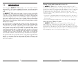
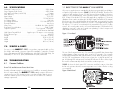
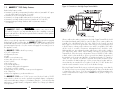
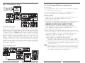
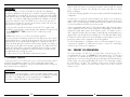
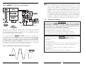
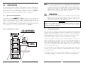
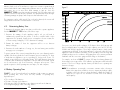
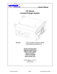
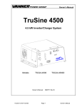
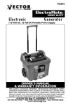
VECTOR “GOLD SEAL” 2/4 YEAR LIMITED WARRANTY PROGRAM
VEC055
This limited warranty program is the only one that applies to this product and it sets forth all the
responsibilities of Vector Manufacturing, Ltd. regarding this product. There is no other warranty
other than those described herein.
This Vector Manufacturing, Ltd. product is warranted, to the original purchaser only, to be free of
defects in materials and workmanship for two years from the date of purchase without additional
charge. This warranty may be extended to four years from date of purchase by paying an
Extended Warranty fee (see below). The warranty does not extend to subsequent purchasers or
users. Vector Manufacturing, Ltd. will not be responsible for any amount of damage in excess of
the retail purchase price of the product under any circumstances. Incidental and consequential
damages are specifically excluded from coverage under this warranty.
This product is not intended for commercial use. This warranty does not apply to accessories or
damage to units from misuse or incorrect installation. Misuse includes wiring or connecting to
improper polarity power sources.
RETURN/REPAIR POLICY: Defective products, other than accessories, may be returned postage prepaid to Vector Manufacturing. Any defective product, other than accessories, that is returned to
Vector Manufacturing within 30 days of the date of purchase will be replaced free of charge. If
such a product is returned more than 30 days but less than two years from the purchase date,
Vector Manufacturing will repair the unit or, at its option, replace it free of charge. If The Extended
Warranty was activated, this repair or replacement period extends to four years from the purchase
date.
MAXXSST 2200
TM
POWER INVERTER
2200 WATT CONTINUOUS / 4500 WATT PEAK
CONVERTS 12 VOLT DC TO 110 VOLT AC
If the unit is repaired, new or reconditioned replacement parts may be used, at Vector
Manufacturing’s option. A unit may be replaced with a new or reconditioned unit of the same or
comparable design. The repaired or replaced unit will then be warranted under the terms of the
remainder of the warranty period. The customer is responsible for the shipping charges on all
returned items. During the warranty period, Vector Manufacturing, Ltd. will be responsible for the
return shipping charges.
LIMITATIONS: This warranty does not cover accessories, bulbs, fuses and batteries, defects resulting
from normal wear and tear (including chips, scratches, abrasions, discoloration or fading due to
usage or exposure to sunlight), accidents, damage during shipping to our service facility,
alterations, unauthorized use or repair, neglect, misuse, abuse, failure to follow instructions for
care and maintenance, fire, flood and acts of God.
If your problem is not covered by this warranty, call our Technical Support Department at
(954) 584-4446 Ext. 19 for general repair information and charges if applicable.
STATE LAW RIGHTS: This warranty gives you specific legal rights. Some states do not allow
limitations on how long an implied warranty lasts or the exclusion or limitation of incidental
or consequential damages, so the exclusions or imitations stated herein may not apply. This
warranty gives the purchaser specific legal rights. Other rights, which vary from state to state, may
apply.
TO REQUEST WARRANTY SERVICE FOR THIS PRODUCT: Contact Vector Manufacturing Technical
Support by telephone, fax or mail. We suggest that you keep the original packaging in case you
need to ship the unit. When returning a product, include your name, address, phone number,
dated sales receipt (or copy) and a description of the reason for return and product serial number.
After replacing the unit, we will attempt to return it to you within four weeks.
WARRANTY ACTIVATION: Please complete Warranty Activation Card and mail to Vector
Manufacturing. If activating Additional Extended Two Year Warranty, (total two years) enclose
check or money order for $150.00 Enter “VEC055” as Model and Power Inverter as “Product
Type”. All Vector Manufacturing, Ltd. products must be registered within (30) days of purchase. To
activate this warranty, mail completed registration form, a copy of the original sales receipt and
required fee (if activating extended warranty) to:
WARRANTY REGISTRATION
VECTOR MANUFACTURING, Ltd.
4140 S.W. 28th Way; Fort Lauderdale, Florida 33312
ADVANCED
MOSFET
TECHNOLOGY
OWNER’S MANUAL
THIS MANUAL CONTAINS IMPORTANT INFORMATION REGARDING SAFETY, OPERATION,
MAINTENANCE AND STORAGE OF THIS PRODUCT. TO AVOID POSSIBLE INJURY OR PROPERTY DAMAGE,
PLEASE READ THIS INSTRUCTION MANUAL CAREFULLY BEFORE USING THIS PRODUCT.
4140 S.W. 28th Way, Ft. Lauderdale, FL 33312
Tel: (954) 584-4446 Fax: (954) 584-5556 Toll Free: (866) 584-5504
www.vectormfg.com
IMPORTANT SAFETY INFORMATION
To ensure reliable service, your power inverter must be installed and used properly.
Please read the installation and operating instructions thoroughly prior to installation
and use. Pay particular attention to the WARNING and CAUTION statements in
this manual. The CAUTION statements advise against certain conditions and
practices that may result in damage to your inverter. The WARNING statements
identify conditions or practices that may result in personal injury.
READ ALL INSTRUCTIONS BEFORE USING THIS POWER INVERTER
PROBLEM: LOW POWER OUTPUT
POSSIBLE CAUSE
SUGGESTED SOLUTION
Inverter overloaded.
Reduce current load to 2200 watts
maximum for continuous operation.
Input Voltage below 11.5 VDC.
Recharge or replace battery (batteries).
Input 12 VDC cable is not heavy
gauge, and/or cable run is too long.
See Appendix A.
WARNINGS
TO REDUCE THE RISK OF FIRE, ELECTRIC SHOCK, EXPLOSION OR INJURY:
•
•
•
•
•
Do not connect to AC distribution wiring
Remove appliance plug from outlet strip or turn off inverter before
working on the appliance
DO NOT locate inverters in an area, room or compartment where
explosive or flammable fumes might be present
Unplug appliances when servicing
KEEP AWAY FROM CHILDREN—THIS IS NOT A TOY
Multiple outlet power strips with switches and circuit breakers only interrupt
power to the “hot” receptacle terminals. The “neutral” terminals remain
powered with respect to the “ground” terminals
CAUTIONS
•
NO USER-SERVICEABLE COMPONENTS INSIDE. OPENING UNIT
WILL VOID WARRANTY
• Do not use with positive ground electrical systems (the majority of
modern automobiles, RVs, and trucks and boats are negative ground)
Reverse polarity connection will result in a blown fuse and may cause
permanent damage to the inverter and will void the warranty
• Grounding the Neutral will cause the inverter to shut down
• Do not operate this inverter if it is wet
• Do not install in engine compartment - install in a well ventilated area
• Not approved for use in conjunction with medical equipment
IMPORTANT CABLE INFORMATION
Substantial power loss and reduced battery operating time results from inverters installed with cables that are not able to supply full power. Symptoms of
low battery power can result from cables that are either excessively long or an
insufficient gauge. The installer/operator should be especially aware of the
requirements to maintain secure, electrical connections. Cable insulation and
ampacity (ampere capacity) must be the appropriate type for the environment. If
you want to purchase a prepared cable and fuse set contact Technical Support at
(954) 584-4446 or toll free at (866) 584-5504, ext. 19.
PROBLEM: LOW BATTERY ALARM SOUNDS CONTINUOUSLY
POSSIBLE CAUSE
SUGGESTED SOLUTION
Inadequate power or
excessive voltage drop.
Clean and reconnect cables and
reduce input cable length.Use
correct gauge and length wire.
9.0
MAINTENANCE
The MAXXSST™ 2200 inverter requires minimal maintenance. However, for
optimum performance, perform the following as required.
1.
2.
3.
4.
Turn OFF the converter using the front panel ON/OFF switch.
Disconnect the inverter by removing the DC power fuse.
Check and tighten all electrical connections including the ground.
Using a non-metallic vacuum cleaner hose, vacuum the fan area and other
air slots.
5. Clean any dirt and dust from the outside of the unit with a damp cloth.
6. Reconnect the fuse and resume operation
10.0 APPENDIX A CABLE REQUIREMENTS
VEC085 is a two-conductor, cable set 6 feet long with fuse holder attached
and ANL500 fuse. This cable set can be used with the VEC051SST and
VEC055SST power inverters.
Other cables may be used with this 2200 watt inverter. If you are purchasing
wire from an electrical equipment distributor then use the table below as a guide.
The table gives total length (twice the cable length as distance between inverter
and DC source).
CABLE
GAUGE
#2 AWG
#1 AWG
00 (2/0)
AWG
0000 (4/0)
AWG
TOTAL
LENGTH
6 Ft.
10 Ft.
14 Ft.
20 Ft.
3 Ft.
5 Ft.
7 Ft.
10 Ft.
ANL500
ANL500
ANL500
ANL500
*DISTANCE
FUSE
* DISTANCE from battery to inverter (1/2 cable length)
28
CONTENTS
8.2
Troubleshooting Guide
1.0
PROBLEM: NO 110/120-VAC POWER OUTPUT
INTRODUCTION . . . . . . . . . . . . . . . . . . . . . . . . . . . . . . . . . 1
1.1
Basic Tour of Inverter . . . . . . . . . . . . . . . . . . . . . . . . . . 2
POSSIBLE CAUSE
SUGGESTED SOLUTION
1.2
MAXXSST™ 2200 Safety Features . . . . . . . . . . . . . . . . . 3
Inverter switch in OFF position.
Turn inverter ON.
1.3
Warnings, Cautions and Notes. . . . . . . . . . . . . . . . . . 4
Poor contact with 12-VDC battery supply.
Switch OFF the inverter; clean input
terminals, reconnect input terminals
and cable ends; reconnect cables.
Input power source below 10-VDC.
Recharge or replace power
source batteries.
Total appliance current draw
Reduce appliance load to 2200
watts maximum.
Inverter in thermal shutdown condition.
2.0
Ensure inverter is properly connected
to12 VDC power source with
correct polarity. Call Vector™
Customer Support. Remove
overload from inverter. If resetting
the front-panel mounted circuit
breaker(s) does not resolve the
problem, the inverter MUST be
returned to the manufacturer for
professional inspection of the internal
circuitry and internal fuses. DO
NOT ATTEMPT TO OPEN UNIT:
THIS WILL VOID THE WARRANTY.
Tripped circuit breakers on front panel
of inverter
Inspect circuit breakers.
Reset circuit breaker(s).
Excessive input voltage.
Ensure that inverter is connected
to a 12 VDC to 15 VDC
power source.
Short circuit or neutral is grounded.
Correct wiring. Inspect internal
circuit. Correct wiring.
27
...........................5
2.1
Uninterruptible Power Supply (UPS)
2.2
AC Transfer Switch
...........................7
3.0
THEORY OF OPERATION
...........................8
4.0
OPERATION . . . . . . . . . . . . . . . . . . . . . . . . . . . . . . . . . . . 10
Allow inverter to cool down; ensure
adequate air circulation around
unit; reduce current load to 2200
watts maximum.
DC fuse is open (blown)
INVERTER APPLICATIONS
5.0
.................6
4.1
Power Requirements . . . . . . . . . . . . . . . . . . . . . . . . . . 10
4.2
Determining Battery Size . . . . . . . . . . . . . . . . . . . . . . . 13
4.3
Battery Operating Time . . . . . . . . . . . . . . . . . . . . . . . . 13
4.4
Controls, Indicators and Alarms . . . . . . . . . . . . . . . . . . . 15
INSTALLATION . . . . . . . . . . . . . . . . . . . . . . . . . . . . . . . . . . 17
5.1
Input Power Requirements . . . . . . . . . . . . . . . . . . . . . . . 17
5.2
Operating Environment . . . . . . . . . . . . . . . . . . . . . . . . .18
5.3
Installation Sequence . . . . . . . . . . . . . . . . . . . . . . . . . 19
5.4
Quick Operational Checkout . . . . . . . . . . . . . . . . . . . . 20
5.5
Permanent Installation . . . . . . . . . . . . . . . . . . . . . . . . . 21
5.6
Connection To High Output Terminal Block . . . . . . . . . . . . 23
6.0
SPECIFICATIONS . . . . . . . . . . . . . . . . . . . . . . . . . . . . . . . . 25
7.0
SERVICE & REPLACEMENT PARTS . . . . . . . . . . . . . . . . . . . . . 25
8.0
TROUBLESHOOTING . . . . . . . . . . . . . . . . . . . . . . . . . . . . . 25
8.1
Common Problems
. . . . . . . . . . . . . . . . . . . . . . . . . . 25
8.2
Troubleshooting Guide . . . . . . . . . . . . . . . . . . . . . . . . 27
9.0
MAINTENANCE . . . . . . . . . . . . . . . . . . . . . . . . . . . . . . . . 28
10.0
APPENDIX A . . . . . . . . . . . . . . . . . . . . . . . . . . . . . . . . . . . 28
11.0
WARRANTY . . . . . . . . . . . . . . . . . . . . . . . . . . . . . . . . . . . . 29
1.0
“Buzzing” Sound in Audio Systems and/or Snow in TVs
INTRODUCTION
Your new Vector MAXXSST 2200 inverter is one in a series of the most
advanced DC to AC inverters available. With proper care and appropriate
usage, it will give you years of dependable service in your car, truck, RV or
boat.
™
The MAXXSST™ 2200 supplies 2200 watts of continuous power, with a 4500
watt peak, in the form of three household-type outlets that are ready to deliver
110 volt AC power whenever and wherever you need it! The heavy-duty
inverter has enough power to run most household or electronic appliances. It
also comes equipped with battery clips to handle higher amperage/load
applications, such as power tools, stereo amplifiers, vacuums, etc. Added
safety features include automatic shutdown and a low battery alarm to prevent
damage to your battery.
This power inverter is configured with the latest Soft Start Technology (SST).
Before introduction of Soft-Start, high startup currents from large inductive loads
could shut down the inverter. Soft Start improves inverter operation. Three
major features incorporated in SST include: First, gradual voltage ramp-up
during inverter startup. This eliminates failed cold starts under load. Second,
output that momentarily dips in voltage and quickly recovers to allow large
motorized loads to start. This eliminates almost all shutdowns from momentary
overloads. Last, the inverter automatically re-starts when an overload that
causes inverter shutdown is removed. Previously, manual reset was required.
The MAXXSST™ 2200 inverter is shielded to minimize interference with TV
signals. Ensure that the ground screw on the High Output Terminal is wired to chassis
ground. Ensure that the TV antenna provides an adequate “snow free” signal and
that the antenna cable is high quality and shielded without the inverter operating.
The problem may not be with the inverter. However, in some cases, some
interference may be visible, particularly with weak TV signals. Try the following
corrective measures:
1. Position the TV and antenna further away from the inverter if it is the cause of
interference. Adjust the antenna or use commercial cable hookup (if possible)
for best results.
2. Do not operate high-power appliances or tools when you are watching TV.
Inverter Shuts Down or Battery Fuse Opens
The MAXXSST™ 2200 inverter will continuously deliver 2200 watts or 20
amps of AC power. It will deliver up to 4500 watts or 41 amps for short
periods of time. After a few seconds at this power output level, the inverter may
shut itself down or the battery fuse will open. Replace the battery fuse, if opened.
Reduce the load on the inverter. Allow the inverter to cool for at least 15 minutes
before attempting to start or run a high current draw device.
This power inverter also incorporates a new cooling technology that directly
benefits our customers. The new design more efficiently cools the power
transistors, and combined with Soft Start, dramatically increases reliability and
the life of the product.
1
26
6.0
SPECIFICATIONS
1.1 BASIC TOUR OF THE MAXXSST™ 2200 INVERTER
Maximum Continuous Power . . . . . . . . . . . . . . . . . . . . . . . . .2200 Watts
Surge Capacity (Peak Power) . . . . . . . . . . . . . . . . . . . . . . . . 4500 Watts
No Load Current Draw (switch ON) . . . . . . . . . . . . . . . . . . . . . 1.0 amps
Max. Efficiency . . . . . . . . . . . . . . . . . . . . . . . . . . . . . . . . approx. 90%
Input Voltage . . . . . . . . . . . . . . . . . . . . . . . . . . . . . . . . . . . . 0-15 VDC
Output Voltage . . . . . . . . . . . . . . . . . . . . . . . . . . . . . . 110 VAC 60 Hz
Low Voltage Alarm . . . . . . . . . . . . . . . . . . . . . . . . . . . . . . . . 10.6 Volts
Low Voltage Shutdown . . . . . . . . . . . . . . . . . . . . . . 10.0 Volts Auto Reset
Thermal Shutdown . . . . . . . . . . . . . . . . . . . . . . . . . . . . . . . . Auto Reset
Wave Form . . . . . . . . . . . . . . . . . . . . . . . . Modified Sine Wave (MSW)
Front Panel Circuit Breakers . . . . . . . . . . . . . . . . . . . . . . . . . Dual 15-amp
Output Receptacles . . . . . . . . . . . . . . . . . . . . . Two U-ground, 15 ampere,
. . . . . . . . . . . . . . . . . . . . . . . . . . . . . . . . . . .North American Standard
High Output Terminal Block . . . . . Supplies up to 20 amps to screw terminals
Power Transistor Type . . . . . . . . . . . . . . . . . . . . . . . . . . . . . . . MOSFET
Weight . . . . . . . . . . . . . . . . . . . . . . . . . . . . . . . . . 23.8 lbs. (10.8 kg)
Length . . . . . . . . . . . . . . . . . . . . . . . . . . . . . . . . . . . 20.8 in. (53 cm)
Width . . . . . . . . . . . . . . . . . . . . . . . . . . . . . . . . . . . . 7.8 in. (20 cm)
Height . . . . . . . . . . . . . . . . . . . . . . . . . . . . . . . . . . . 6.30 in. (16 cm)
7.0
AC power is supplied via two standard North American grounded,household-type
receptacles (U-ground) as shown in FIGURE 1 (THE FRONT PANEL). This allows the
connection and operation of most 110 VAC-powered electrical and/or electronic
appliances using a standard plug. Each U-ground receptacle is separately protected
by a 15-amp circuit breaker. For heavy duty applications, appliances or electrical
distribution circuits can be wired directly to the High Output Terminal Block. The terminal
block wires are color-coded: black-hot; white-neutral and green-ground. Note that
the High Output Terminal Block MUST be wired to a user-supplied dual ganged
25 Ampere, 110 volt AC circuit breaker if the terminal block is used. For safety
reasons, the circuit breaker can be a Ground Fault Interrupter (GFI) breaker if the
distribution wiring AC outlets are located near plumbing or where unsupervised
small children will have access to them.
Figure 1. Front Panel.
SERVICE & PARTS
For service on the MAXXSST™ 2200, or to purchase a prepared cable set, fuse,
fuse holder, and terminal connectors required for installation, contact the Customer
Service Department at: VECTOR Manufacturing, Ltd. 4140 S.W. 28th Way, Fort
Lauderdale, FL 33312 Tel. (954) 584-4446 • Fax (954) 584-5556
8.0
TROUBLESHOOTING
8.1
Common Problems:
Power Tools and Microwave Ovens Won’t Start
Read the information panel on each power tool carefully to accurately determine
the tool’s input wattage. The MAXXSST™ 2200 wattage output is sufficient to
operate most power tools and microwave ovens but remember that the power
needed to start the power tool may be as much as 2 to 6 times its continuous
wattage requirements.
The rest of the front panel items are: One vertically mounted LED bar voltmeter that
indicates battery voltage measured at the inverter’s DC terminals. One vertically
mounted LED bar ammeter that indicates battery current drawn by just the inverter.
An ON/OFF switch that turns off the inverter circuitry, the cooling fan and AC output. A high-temp LED indicator and Overload LED indicator. If either of these light,
the inverter will automatically shut down until the condition improves.
FIGURE 2 shows the back panel DC connectors and fan locations. Note that
the fan only operates when the inverter temperature rises. It shuts off when cooling
is not required.
Figure 2. Back Panel.
GROUNDING
TERMINAL
25
2
1.2
MAXXSST™ 2200 Safety Features
Figure 9. Connections to the High Output Terminal Block.
Built-in Safety Features include:
• Automatic overload (over-temperature) shutdown and reset (activated if AC output
exceeds 4500 watts for more than 3 seconds)
• Automatic AC short-circuit shutdown and reset
• Automatic low voltage audible alarm and reset (sounds at 10.6 volts input)
• Automatic low-voltage shutdown and reset (activates at 10.0 volts DC)
• Automatic high-input voltage shutdown and reset (activates at above
15 volts DC)
25
WARNING
The MAXXSST™ 2200 output should be treated with the same caution as any
110 volt AC circuit. It is very important that anyone who is installing or using the
inverter read and follow all instructions provided in this manual to ensure optimum
safety and performance.
When you use the high output direct wiring feature with the required user-supplied
dual ganged 25 amp circuit breaker, the MAXXSST™ 2200 can be installed with
an automatic transfer switch or manual transfer switch. Then, when utility power (or
generator-supplied power) is lost, the inverter will supply the necessary power to
the appliance circuits.
The MAXXSST™ 2200 is ideal for powering:
• TV/VCR combinations
• Refrigerator/freezers
• Lights
• Radio receivers/transceivers
• Heavy duty power tools & chargers
• Stereo systems
• Microwave ovens
• Household appliances
• Computers and peripheral equipment
• Dry and/or wet/dry vacuums
• Sump pumps, motors, and other electric-powered equipment
• Air compressors
• Many more appliances, products and devices
(Rear Panel of Inverter)
All wire cable used to make a connection to the High Output Terminal Block should
be insulated and rated at #10 AWG to carry 30 amps. These common cables are
normally color coded Black for the “hot” wire; White for the “neutral” wire and
bare Copper or Green for the ground wire. If this wiring is to be permanently used
in fixed locations, ordinary single conductor wire cable is acceptable. If the cable
will be used in a mobile environment, multi-stranded wire should be used.
Multi-stranded wire can withstand constant cable flexing, while single conductor
(one strand wire) cable cannot. When making connections to the High Output
Terminal Block, follow the wiring configurations shown in FIGURE 9, That is: black
to black, white to white and bare or green to ground. Note that the designation of
the terminals on the inverter are labeled L, N, and ground symbol. “L” stands for
“load”, the “hot” terminal. "N" stands for "Neutral". The breaker should be mounted in a metal box for that breaker type. When you purchase a breaker and box,
ensure that they are intended for use together. Locate the 110 VAC breaker box
near the inverter terminals to ensure access to the breaker if it trips.
If the High Output Terminal block wiring is used with existing wiring, ensure that the
AC from the inverter is protected with a dual ganged 25 amp circuit breaker and
is isolated from other sources of AC by using a transfer switch that simultaneously
switches Neutral and Hot output. Refer to FIGURE 4 as a guide to wiring to a
transfer switch.
The MAXXSST™ 2200 uses a 12 VDC power source like those found in 12 VDC
motor vehicles or boats or it can be operated using multiple battery configurations
with commercial battery chargers or solar battery chargers. For most heavy-duty
applications, a multiple battery configuration and the use of deep-cycle batteries
is a requirement.
3
24
16. Connect an insulated wire (at least 12 AWG) between the grounding screw
on the inverter’s high output terminal block (see FIGURE 9 - the green wire) and
a solid electrical ground to minimize possible electrical noise generation in
TVs and radios.
Also connect a grounding wire to the terminal attached to the inverter’s
enclosure. DO NOT connect this wire to the negative DC input terminal.
17. Check to ensure that all electrical connections are tight.
18. Ensure that the inverter’s ON/OFF switch is OFF.
19. Insert the fuse into the fuse holder. There may be some sparking.
20. Turn on the inverter and apply a test load to the AC outlets.
21. Observe the LED bar meters and ensure that adequate battery voltage is
present. If you have applied a 600 watt test load, the ammeter should display
50 amps. If it does not:
A. Check all connections, and tighten any loose connections.
B. Ensure that the battery has an adequate charge.
C. Check the front panel voltmeter to see if adequate voltage is applied
If voltage is low, the cables may be too long or the gauge too light.
D. If steps A through C do not correct the problem, contact Vector Technical
Support Department (954) 584-4446 Ext. 19 for professional direction.
22. Replace the terminal cover and secure with the screws.
5.6. Connection to High Output Terminal Block
External wiring connected to the high output terminal block REQUIRES a
user-supplied dual ganged 25 Amp circuit breaker to protect appliances.
FIGURE 9 shows typical wiring connections using a standard circuit breaker. There
are several types and many manufacturers of circuit breakers available; this
illustration is an example of only one type. A 30 amp Ground Fault Interrupter (GFI)
breaker should be used if the outlets or devices are around water.
Use a Square D type QO230GFICP Plug-On Circuit Breaker And Ground Fault
Interrupter. The physical size of this breaker requires a 70 Ampere load center box
rated at 120/240V single phase ( 3-wire Square D model HOM2-4L70S ). The
breaker has a pig-tail wire that must be connected to the grounding bar inside the
load center box. The Breaker is internally ganged so that both Neutral and Hot
circuits from the inverters’ High Output Terminal Block are switched simultaneously. If
you choose to use a conventional current-only circuit breaker, both Neutral and Hot
must be interrupted. You can use a 50 amp load center because a ganged nonGFI breaker is physically smaller than a GFI breaker.
With installations using multiple batteries, the inverter can be operated from one of the
vehicle or vessels’ 12 volt batteries, so there’s always one battery with adequate
charge to start an engine.
Other MAXXSST™ 2200 features include a high-surge capability (up to 4,500
watts), which is required to start heavy loads such as motors and other inductive
devices.
1.3
Warnings, Cautions and Notes:
It is very important that any operator/installer of the inverter read and follow the
installation and operation instructions included in this manual. In particular, close
attention should be paid to the WARNINGS (possibility of serious injury or death),
CAUTIONS (possibility of damage to the inverter and/or other equipment) and
NOTES (included to assist you in achieving the maximum utility and the longest
working life from this advanced-design inverter).
WARNING ABOUT AC OUTPUT
The MAXXSST™ 2200 is an industrial grade, heavy-duty device that produces
voltages similar to commercial AC power. There are special precautions that must
be taken when you are working with this inverter output. First, Hot and Neutral terminals are both powered with respect to ground. Consider this output as a threewire system and NEVER assume that all circuit wires are unpowered because a
front-panel breaker trips. A breaker trips only because the Neutral to Hot load is
greater than 15 amps. The NEUTRAL IS STILL POWERED WHEN A FRONT-PANEL
BREAKER TRIPS. Second, NEVER connect ANY Neutral terminal or wire to ground.
This shorts the output and the inverter will shut down.
The inverter has independent front panel circuit breakers located directly below the
outlet circuits they protect. IF ONLY ONE FRONT-PANEL BREAKER TRIPS,
ALL OTHER OUTPUTS ARE STILL POWERED, INCLUDING THE HIGH OUTPUT
TERMINAL CIRCUITS.
WARNING
NO USER-SERVICEABLE COMPONENTS INSIDE.
OPENING UNIT WILL VOID WARRANTY.
APPLIANCE CAUTIONS
DO NOT plug small appliances into the inverter AC receptacles to directly recharge
their nickel-cadmium batteries. Always use the recharger provided with that appliance.
Do NOT plug in battery chargers for cordless power tools if the charger carries a
warning that dangerous voltages are present at the battery terminals.
23
4
Not all fluorescent lamps operate properly with this type of inverter. If the bulb
appears to be too bright, or fails to light, do not use the lamp with this inverter.
Some fans with synchronous motors may slightly increase in speed (RPM) when
powered by the inverter. This is not harmful to the fan or to the inverter.
NOTE: These installation procedures are for locally purchased wire fuse and fuse
holders. If a VEC085 cable set is purchased use the instructions provided
with the set.
1. Using tools and hardware, mount the inverter to the flat surface that you
have selected.
Certain rechargers for small nickel-cadmium batteries can be damaged if plugged
into the inverter. In particular, two types of appliances are susceptible to damage:
2. Mount the fuse holder to its mounting surface using appropriate hardware.
Ensure that the mounting hardware does not touch any of the fuse holder
contacts or fuse contacts. Ensure that the fuse is removed from its holder.
• Small, battery-operated appliances such as flashlights, cordless razors and tooth
brushes that can be plugged directly into an AC receptacle to recharge
3. Measure the cable twice before marking the cable for cutting.
• Certain battery chargers for battery packs that are used in some cordless
hand-tools. Chargers for these tools have a warning label stating that
dangerous voltages are present at the battery terminals
4. Cut one cable length to fit between the negative (-) connection power source
and the inverter’s negative terminal, leaving a little slack in the cable.
5. Cut the remaining length of cable to be able to connect from the positive (+)
power source terminal to one side of the fuse holder, leaving a little slack.
DO NOT use the inverter with the above two types of equipment.
6. Cut the remaining length of cable to connect the other side of the fuse holder to
the positive (+) terminal on the back panel of the inverter.
The majority of portable appliances do not have this problem. Most portable
appliances use separate transformers or chargers that plug into AC receptacles to
supply a low-voltage DC or AC output to the appliance. If the appliance label
states that the charger or adapter produces a low-voltage DC or AC output (30
volts or less), there should be no problem powering that charger or adapter.
7. Strip the insulation to 1-inch (2.45 cm) from the ends of each of the three cables.
NOTE: Some very flexible versions of 00 cables may not fit into the ring
terminals as they are slightly larger in diameter than the terminal’s
opening. If necessary, you can remove up to 10% of the wire strands.
2.0 INVERTER APPLICATIONS
Aside from issues of supplying power to higher wattage appliances, the inverter
must be supplied with a constant source of high current DC from a bank of batteries.
At full 2200 watt load, the DC input requirements are up to 220 amperes at
12 volts DC. The inverter has connections for direct wiring to AC power distribution circuits, and certain warnings must be observed during installation. Miswiring
can be dangerous.
8. Sweat-solder the remaining copper strands at the inverter ends of the appropriate
cables onto the ring terminals to ensure a good connection. For safety reasons,
do this in an open space because it may require the use of a propane torch.
9. Crimp or clamp on a heavy-duty, battery-connection terminal to the other end of the
negative (–) and positive (+) cable. Connect the negative (–) cable battery terminal
to the negative (–) battery terminal connector.
10. Ensure that the inverter power switch is in the OFF position (See FIGURE 1).
11. Attach the ring terminal of the negative (–) cable onto the black stud terminal
(–) on the inverter back panel and tighten the retaining nut.
12. Connect the battery connector to the negative (–) battery terminal.
13. Attach the the positive (+) cable into the red stud terminal (+) on the inverter’s
back panel (See FIGURE 2) and tighten the retaining nut.
14. Connect the other end of the (+) positive cable to one terminal of the heavy-duty
fuse holder.
25
15. Connect the other conductor of the heavy-duty fuse holder to the positive (+)
battery terminal.
16. Replce the stud terminal covers and secure with supplied screws.
5
22
5.5. Permanent Installation
5.5.1 Preparation for Permanent Installation
Note than a prepared heavy duty 6 ft. cable kit can be purchased from
your dealer or Vector Manufacturing. Call Tech Support at:
(954) 584-4446 or (866) 584-5504 Ext. 19 ask for VEC085 cable set.
For permanent installation to heavy-duty battery power you will need:
• Ring terminals to connect two 00 (2/0) cables to the battery bank
• A single length of not more than ten feet of 00 (2/0) multi-stranded flexible
insulated cable
• A 500 ampere low voltage fuse and fuse holder type ANL
• Mounting screws, bolts and nuts for mounting the inverter and the fuse holder
• Tools to drill holes for mounting the inverter and fuse holder
• Lead-tin solder, flux, propane torch and an igniter for the torch
• Sharp utility knife to cut insulation
• Hacksaw to cut the 00 (2/0) cable
• Pair of diagonal cutters to trim away some cable strands if necessary
• Ring terminals connector for 00 2/0 cable for connection to battery (batteries)
Installation Notes:
The MAXXSST™ 2200 has four slots in its mounting bracket that allow the unit
to be fastened against a bulkhead, floor, wall or other flat surface. Ideally, the
mounting surface should be cool to the touch. It is more electrically efficient to use
longer AC wiring than DC wiring, so install the inverter as close as possible to the
12 VDC power source.
The inverter can be operated in any position, however, if it is to be mounted on a
wall mount it horizontally so that indicators, switches, outlets and terminal blocks
located on the front panel are visible and accessible. Look for a convenient place
to mount inverter and the fuse holder. Take the length of cable and do a trial routing of the cable. Don’t do any cutting at this time. Take a look at FIGURE 8.
Measure the cable path and ensure that either the positive cable run to the battery
or negative cable run to the battery does not exceed 4 feet. Reposition the
inverter and fuse holder if necessary. Remember and observe the other
environmental requirements described earlier.
After you have selected an appropriate location for the inverter and fuse block,
proceed with the actual installation of the inverter.
Contact Vector™ for any further installation information or questions. Your can purchase
fuses, fuse holders, and 4/0 cable or cable battery connectors from your local
electrical supplier or from Vector Technical Support at (954) 584-4446 Ext. 19.
Read the following applications and comply with them, and your
MAXXSST™ 2200 will give you years of reliable service.
Never connect the inverter’s AC output to an already powered AC distribution system.
If you will only be operating the MAXXSST™ inverter occasionally and manually,
using the two outlets on the front panel of the inverter, then you can disregard the
next two sections (2.1 and 2.2), except for battery charging requirements.
Two primary ways for connecting to an AC distribution system are provided in
sections 2.1 and 2.2.
2.1 Uninterruptible Power Supply (UPS)
One way is to continuously operate the inverter from the battery bank, simultaneously
replacing the charge on the battery bank using an AC-powered 12 Volt battery
charger or other means of charging the batteries, such as a solar charger system. See
FIGURE 3. The charger must be selected to operate continuously and to be able to
replace the charge on the battery as the inverter operates. In this configuration, the
battery “floats” on the DC from the charger, not really supplying power or being
charged. When outside AC fails, the inverter continues to power the appliances
for the life of the useful charge on the battery bank. When outside AC is restored,
the batteries are recharged as the inverter continues to operate. Battery recharging
must be sized to replace the average daily current supplied by the inverter plus a
little more current. Another requirement is that the battery charging rate cannot
exceed 10% of the rated Ampere Hour (AH) rating of the battery bank, otherwise
the life of the batteries can be dramatically reduced through overcharging. Most
modern battery chargers automatically adjust the charging rate based on the state
of the batteries to which they are connected. For this type of operation, use deep
cycle batteries and avoid charging at too fast a rate.
5.5.2 Permanent Installation Procedures
The cables between the power source and the inverter should be as shown in
FIGURE 8. Be sure to remove the carriage bolts before starting permanent installation.
Inverter DC cables and fuse installation is as follows:
21
6
5.4 Quick Operational Checkout or Emergency Use
Figure 3. Uninterruptible Power Supply.
You will require:
• One heavy-duty jumper cable set with wire rated at #2 AWG or #4 AWG
• One fully-charged automobile battery
• A common, medium head screwdriver for removal of terminal covers
• A pair of slip joint pliers or wrench that fits the terminal nuts
Checkout procedure:
1. Identify the positive and negative terminals on the 12 volt DC battery and
identify the positive and negative terminals on the inverter.
2. Remove the plastic terminal cover.
3. Using the set of heavy-duty jumper cables, attach one red cable clamp to the
(+) terminal bolt and one black cable clamp on the (–) terminal bolt.
WARNING: DO NOT ALLOW CLAMPS TO TOUCH.
2.2 AC Transfer Switch
Another way to configure the inverter is somewhat different in that the inverter is
turned on but does not power the appliance load on the high output terminal block
as long as outside AC is available. The “idle current” of the inverter is a minimum
1.2 amperes. As shown in Figure 4, both the outside AC and inverter output are
connected on opposite sides of a two-position transfer switch. The switch allows
either the outside AC to power the distribution wiring or the inverter to power the
distribution wiring - never both at the same time. The transfer switch can be either
automatic or manual. There will be a momentary disruption of power when
the appliance load is transferred if the transfer switch operates automatically. A
manually operated transfer switch requires human intervention to change the
switch position and engage the inverter output, so there is a delay until the transfer
switch position is changed.
Figure 4. AC Transfer Switch
MAXXSST™ 2200
7
4. Connect the clamps on the other ends of the jumper cables to the
corresponding positive (+) and negative (–) terminals on the 12 volt DC
vehicle battery. There may be some minor sparking observed.
5. Turn the inverter power switch ON.
6. Plug in a lamp with a 100 watt light bulb and switch the lamp ON. If the
lamp works normally, the inverter is functioning properly and you can proceed
to a permanent installation or continue to use the inverter with low wattage
appliances. If the lamp does not light or does not work correctly:
A. Check all connections and tighten any loose connections.
B. Ensure that the source battery has adequate charge.
C. Check the front panel voltmeter to see if adequate voltage is applied.
If voltage is low, the cables may be too long or the gauge too light.
D. If steps A through C do not correct the problem, contact Vector Technical
Support Department (954) 584-4446 or (866) 584-5504 Ext. 19 for
professional direction.
NOTE: Any appliance or tool used for this type of test or emergency operation
must be designed for 110 VAC (115 VAC RMS), 60 Hertz (Hz) and
have a power consumption of 800 watts or less. The jumper cables are
not designed for operating the inverter at full power.
20
CAUTIONS:
This device supplies 110 VAC electrical power directly to the appliances
through two standard, North American 3 conductor receptacles and through
the output hard-wire terminal block. The circuit connected to the High Output
Terminal Block requires a dual ganged 25 amp circuit breaker (not included).
See Figure 1 to locate the High Output Terminal Block. Installation of external
wiring is described in section 5.6. NEVER try to use the inverter with any 12
VDC power source that uses a positive ground. Most modern vehicles, boats,
and aircraft use negative ground systems.
Do not connect the ground wire from the inverter to the DC negative input.
• CHECK to ensure that the combined loads of the appliances being powered
by the MAXXSST™ 2200 inverter DO NOT continuously exceed
2,200 watts.
• NEVER place items on or over the inverter during operation.
The inverter generates heat during operation like any high power device and it
must be placed where cooling air can be drawn into the unit by its internal fan,
and heated air can be expelled and dissipated. For optimum operation, the
inverter should be placed or mounted on a flat surface; ideally, a normally cool
metal surface to help diffuse the heat that is generated. Two cables and a fuse
rated at 500 amps will be required (not supplied). Each should be no longer
than shown in the table in Appendix A to allow for full power operation and to
provide flexibility in positioning the inverter.
For safety reasons, keep small children away from the inverter.
5.3 Installation Sequence
To wire the inverter to a 12 VDC power source, observe the following cautions
and follow the installation sequence for Quick Operational Checkout and
Permanent Installation. External AC wiring is described after all DC wiring procedures and tests are accomplished.
When outside AC power is restored, the transfer switch should be returned
to the outside AC position. This off-loads the inverter and allows for faster
battery recharging.
Use the same charging guidelines in the previously described UPS (floating battery)
configuration.
You may have to contact an electrical supply house and/or your electrician to
install a transfer double-pole, double-throw ganged transfer switch rated at 25
amperes AC or greater. Both the Neutral and Hot must be simultaneously switched
to ensure that Neutral is NEVER connected to ground.
Common unattended applications for UPS (floating battery) and automatic transfer
switch configurations are for powering: sump pumps, safety lighting, communications
equipment, burglar alarm systems and computer systems. If a transfer switch is
used, computers should be also powered by a small capacity uninterruptible power
supply (UPS) to “ride through” the period that power is lost during the transfer delay.
If outside AC will not share an AC power distribution system with the Power Force
Inverter, the transfer switch configuration can be disregarded.
The UPS “floating battery” configuration can be used if uninterrupted AC power is
a requirement, regardless of whether direct wiring or inverter AC outlet plug-in
connections are used to power appliances.
3.0
THEORY OF OPERATION
The inverter changes 12 VDC into 110 VAC RMS, electrical power. This is
accomplished in two steps. See FIGURE 5. The first step raises the 12 VDC input
to 145 VDC. The advanced design of the DC-to-DC first stage uses modern
high-frequency conversion techniques that supersede bulky and heavy transformers
found in older, less technologically-advanced inverters. The output stage changes
the 145 VDC to 110 VAC. This solid-state circuitry ensures excellent overload
protection and the ability to operate reactive loads such as those found in
inductive motors.
CAUTIONS:
Ensure that DC connection polarity is correct. Reversed polarity will blow a fuse
and may cause permanent damage to the inverter. The manufacturer’s warranty
does NOT cover damage due to reversed polarity. Review Figure 2, if
necessary, to identify the location of the DC terminals.
19
8
Figure 5. MAXXSST™ 2200 Inverter Simplified Diagram.
NOTE: Vector Manufacturing recommends that for typical heavy-duty uses, a ANL
500 or equivalent (capable of handling 500 amps for a few seconds)
main buss fuse be added to the power source positive cable as close as
possible to the power source (battery) positive terminal. The fuse
amperage must be sized to allow simultaneous operation of all the AC
appliances to be powered, with delay characteristics that allow for the
momentary high start-up current requirements of inductive loads. Use the
recommended fuse block (fuse holder) and fuse or an electrical equivalent.
For full rated output and motor start-up surge output, ensure that the
installation is configured to handle the full load. Figure 8 is also used as a
guide when the cables are measured for actually installing the inverter.
5.2
Operating Environment
WARNINGS
DO NOT locate the MAXXSST™ 2200 in an area, room or compartment
where explosive or flammable fumes might be present. Typically, these areas
are: the engine room or engine compartment of a gasoline-powered vehicle or
boat and small, closed, unvented battery compartments.
Internal
Inter
nal
The inverter’s output stage uses multiple banks of metal-oxide semiconductor
field-effect transistors (MOSFETs). This stage functions as a high-power bipolar
switch, alternately applying opposite polarity to the AC outlet and the high output
AC terminal block hot and neutral terminals.
The 110 VAC output of the MAXXSST™ 2200 is in the form of a modified sine
wave (MSW) as shown in FIGURE 6. This type of waveform has the same energy characteristics as the sine wave of commercial electrical power. The modified
sine wave is superior to the 100% square wave output (not shown) produced by
most other DC-to-AC inverters on the market. A modified sine wave, as opposed
to a square wave, is vital to the efficient and proper operation of certain appliances such as computers, TVs and certain electronic equipment.
Figure 6. Modified Square Wave and Sine Wave Comparison.
In all marine applications, DO NOT install the inverter below or near the
waterline and keep the unit away from moisture or water.
Use ONLY non-corrosive marine fasteners and fittings for installation.
Use of shock-absorbent/insulating materials is strongly recommended.
CAUTION:
To avoid possible dangerous conditions, the MAXXSST™ 2200 must be
located where:
1. The unit is kept dry.
2. Air temperature is between 30°F (-1°C) non-condensing and 105°F (40°C).
3. At least three inches of clearance from other objects is maintained for
cooling airflow.
4. The unit is not exposed to direct heat or sunlight or to explosive or
flammable fumes.
5. The unit is as close to the DC power source as possible.
110 VAC
110 VAC
9
18
5.0
INSTALLATION
The inverter will provide you with up to 2,200 watts of continuous, electrical power
(4,500 watt peak) at 110 VAC when powered by a 12 VDC source such as is
found in a vehicle, boat or multiple battery configuration as shown in FIGURE 8.
This manual does not describe all of the possible types of battery configurations,
battery charging configurations and battery isolation configurations.
5.1
NOTE: The 110 VAC output of the inverter is a modified sine wave that produces
115 VAC AC Voltage. Because of wave-shape differences, if you measure
the output of the inverter using standard digital or analog voltmeters, these
instruments will not read the voltage correctly. Unless a true RMS reading
voltmeter such as a “Fluke 87”, “Fluke 8060A”, “Beckman 4410” or “Triplet
4200” is used, the reading will be from 2 to 20 volts low.
4.0
Input Power Requirements:
To properly operate the MAXXSST™ 2200 the DC power source must provide
between 11.0 and 15.0 VDC and nominally at 220 Amps. This DC power source
must be a well regulated DC power supply as typically found in vehicular and
deep-cycle marine batteries. The DC power source may also be two 12 volt
batteries connected in parallel. On larger applications the power source may
be several batteries connected in parallel as shown on FIGURE 8.
CAUTION:
Appliances such as large microwave ovens will normally draw more current than
they are rated and could possibly overload the inverter when operating
simultaneously with other appliances.
4.1.
Figure 8. Multiple Battery Installation.
+
4-6 FEET OF WIRE
ANL
MAXXSST™ 2200
POWER
INVERTER
MAX OF 5 FEET OF 00 (2/0)
OR 6 FEET OF 0000 (4/0) WIRE
(VEC085) AND FUSE
17
OPERATION
NOTE: Ensure that the total continuous power consumption of all tools and/or
appliances connected to the inverter (and in use) does not exceed 2,200
watts. Also ensure that the start-up wattage for inductive loads does not
exceed 4,500 watts for more than a few seconds.
Power Requirements:
Most electrical tools, appliances and audio/video equipment have labels that
show the unit’s power consumption in amps or in watts or both. To avoid inverter
shutdown and possible damage to the inverter, take care to avoid exceeding the
2,200-watt rating of this unit. If the power consumption of the tool or device is
rated in amps, multiply the amps by 110 VAC to determine the wattage.
For instance, a power tool rated at 4 amps will draw 400 watts. The inverter has
built-in overload protection so that if you do exceed the 4,500 watt peak limit, the
inverter will automatically shut down. Once the excessive load is removed, the
inverter can be restarted and resume normal operation. Note: If overload shutdown
occurs, turn OFF the unit and turn back ON to restart. The ON/OFF switch is located
on the front panel of the inverter.
The inverter handles resistive loads the easiest; however, larger resistive loads such
as electric stoves or heaters could draw more wattage than the inverter can deliver
on a continuous basis.
The following chart shows the approximate amperage at 110 VAC and the
corresponding wattage at 110 VAC for various common tools and appliances.
10
APPLIANCE
AMPS@110VAC
WATTS@110VAC
LAPTOP COMPUTER
HOUSEHOLD POWER MIXER
240-WATT STEREO/AMPLIFIER
REFRIGERATOR
3/8” VARIABLE SPEED DRILL
VARIABLE SPEED JIG SAW
10-SPEED BLENDER
BELT SANDER
3/8” REVERSIBLE DRILL
HOUSEHOLD FOOD PROCESSOR
COMPUTER AND MONITOR
PORTABLE VACUUM
8-CUP COFFEE MAKER
ELECTRIC TRIMMER
1/2” HAMMER-DRILL
RECIPROCATING SAW
VACUUM CLEANER
1-1/8” ROTARY HAMMER
1/6 H.P. SUBMERSIBLE SUMP PUMP
COMPACT MICROWAVE OVEN
2-SLICE TOASTER
HEAVY-DUTY WORKLIGHT
14” CHAIN SAW
42” FAN
200 MPH BLOWER/VAC
16” CHAIN SAW
WET-DRY VAC, 6 H.P., 16 GALLONS
10” BENCH SAW
FULL-SIZE MICROWAVE OVEN
12” COMPOUND MITER SAW
12-1/2” PORTABLE PLANER
HEAVY-DUTY 7-1/4” CIRCULAR SAW
14” CHOP SAW
0.5
2
2.2
3
3
3
3.2
3.4
3.5
3.6
4
4.6
5.5
5.5
5.5
6
7.2
7.8
8
8.5
8.8
9
10
10.3
12
12
12
13
14.5
15
15
15
15
55
240
265
360
360
360
375
410
420
430
450
540
650
660
660
720
865
940
960
1020
1050
1080
1200
1235
1440
1440
1440
1560
1750
1800
1800
1800
1800
Low Battery Alarm:
An audible alarm will sound when:
1. The 12 VDC power supply voltage drops down to 10.6 volts. This indicates
that the power source (battery) needs to be recharged or there is an excessive
voltage drop between the battery power source and the inverter.
2. The inverter is overloaded.
3. The inverter is in thermal shutdown.
NOTE: It is normal for the alarm to sound when the MAXXSST™ 2200 is being
connected to, or disconnected from, a 12 VDC power source. This does
NOT indicate a problem. However, if this alarm is heard, except as
described, discontinue inverter operation and recharge the battery before
further use. If the voltage drops to 10.0 VDC, the inverter will automatically
shut down.
If the low voltage alarm sounds when the battery power source is fully charged,
refer to the troubleshooting table for possible causes and remedies.
4.4.4
Circuit Protection
The inverter has electronic circuit protection. The two front panel mounted 15 amp circuit
breakers can be manually reset in the event they trip due to an overload or short circuit
condition. If the High Output Terminal Block is used, a user-supplied dual ganged
25 ampere circuit breaker MUST be wired to protect the external wiring and
devices connected to it.
WARNING
The inverter is an industrial grade, heavy duty device that generates high voltage.
The front-panel mounted circuit breakers handle any overload situations by disconnecting AC output to prevent potential damage to the inverter and/or any
equipment that it is powering. If re-setting the front-panel mounted circuit breakers
or the external mounted hardwire circuit breaker does not cure a problem, DO
NOT ATTEMPT TO OPEN THE INVERTER. Opening the inverter, for any reason,
will void the warranty. The unit must be returned to Vector Manufacturing, Ltd. for
testing and repair by professional factory technicians.
NOTE: APPLIANCE SPECIFICATIONS MAY VARY FROM BRAND TO BRAND. THIS TABLE IS OFFERED
ONLY AS A GUIDE TO APPROXIMATE POWER RATINGS. CHECK APPLIANCE MANUALS OR
PRODUCT LABELING FOR ACTUAL RATINGS.
11
16
4.4.
Controls, Indicators and Alarms:
Refer to FIGURE 1 if necessary. The inverter is equipped with an ON/OFF switch
located on the front panel of the inverter.
4.4.1. A green Light Emitting Diode (LED) illuminates when the inverter is
correctly connected to an operating 12 VDC power source.
4.4.2. Two rectangular red LEDs indicate the inverter status:
One red LED illuminates to indicate an over-temperature condition. If this LED
illuminates, switch the inverter OFF. The inverter may be overheating because of
insufficient air circulation or it may be operating above its 2,200 watt rating.
Correct the condition and allow the inverter to cool off for at least 15 minutes
before switching it back ON. If the inverter has shut itself down due to an
over-temperature condition, it will automatically reset and can be restarted once the
unit has sufficiently cooled.
The other red LED illuminates to indicate that the inverter has shut itself off because
of severe overload. Switch the inverter OFF and correct the situation. Then switch
the inverter back ON. Do NOT restart the inverter unless the overload condition
has been identified and corrected.
4.4.3. Two LED bar-graph vertical indicators show the 12 VDC power
supply condition:
One vertical indicator shows the 12 VDC power input supply voltage level in
1 volt increments from 10 volts DC to 15 volts DC. This indicator is color-coded.
Ideally, the voltage should remain in the green area of this display. If the voltage
goes into the red areas at the top or the bottom of this display, the inverter may
shut down. At high input current drain, the indicated DC voltage will be less than
the measured power source voltage due to the voltage drop across the cable and
the connections.
The other vertical indicator shows the amperage being drawn by the inverter in
50 amp increments from 50 amps to 300 amps. This indicator is also color-coded
and the current draw should remain in the green area for long-term operation. The
inverter will operate for short periods of time with the current draw in the yellow
area, but if the current draw rises into the red area, the inverter will automatically
reduce its output voltage to avoid damage and it may shut down.
NOTE: The Amperage Drawn indicator described above ONLY shows the current
draw of the MAXXSST™ 2200 inverter, it does NOT show other possible DC loads connected to the power source (battery).
15
NOTE: THE AC RECEPTACLES ON THE FRONT OF THE MAXXSST™ 2200 ARE
EQUIPPED WITH 15 AMP CIRCUIT BREAKERS. THESE RECEPTACLES
THEREFORE ARE CAPABLE OF MAXIMUM OUTPUT OF 1725 WATTS
EACH (110 VOLTS AC X 15 AMPS). TO USE THE MAXIMUM OUTPUT OF
2,200 WATTS, THE MAXXSST™ 2200 MUST BE CONNECTED TO A
DC POWER SUPPLY CAPABLE OF PROVIDING 220 AMPS AND THE
LOAD SHOULD BE DISTRIBUTED AMONG TWO RECEPTACLES AND/OR
THE HIGH OUTPUT HARD-WIRE AC TERMINAL BLOCK SUCH THAT THE
TOTAL INVERTER OUTPUT IS NOT MORE THAN 2200 WATTS. IF ANY
BREAKERS ARE TRIPPED, REDISTRIBUTE THE LOAD AND RESET THE
CIRCUIT BREAKERS.
A. Power Output - The inverter will operate most AC loads within its power rating
(2200 watts continuous.) When determining whether a microwave oven can be
operated by this inverter, remember that the power rating commonly advertised for
microwave ovens is that of the oven’s cooking power (the power delivered to the
food) not the power actually consumed by the oven. But, some models consume
up to 40% more than the advertised cooking power. Be sure to check the rating
sticker on the back of the oven to determine the actual power draw.
Some induction motors used in refrigerators, freezers, pumps and other motor-operated
equipment require very high surge currents to start them. The inverter may not be
able to start some of these motors even though their rated current draw is within
specifications for this power inverter.
If a motor refuses to start, observe the battery voltage indicator while trying to start
the motor. If the battery voltage indicator drops below 11 volts while the inverter is
attempting to start the motor, this may be why the motor won’t start. Make sure that
the battery connections are tight and that the battery (or batteries) is (are)
fully-charged. If the connections are good and the battery is charged, but the
voltage still drops below 11 volts, you may need to use a larger battery (or battery
combination).
B. Input Voltage - The inverter will operate from input voltages ranging between
10.5 and 15 VDC. If the voltage drops below 10.6 volts, an audible low battery
warning alarm will sound and the voltage indicator will be in the lower red zone.
The inverter will shut down if the input voltage drops below 10.6 VDC. This built-in
feature protects the source battery from being completely discharged.
The inverter will also shut down if the input voltage exceeds 14.7 volts. This protects the
inverter against excessive input voltage. The voltage indicator will be in the upper red
zone. Although the inverter has built-in protection against overvoltage, it may still
be damaged if the input voltage exceeds 15.2 volts.
NOTE: Exceeding the recommended voltage limits will void the
manufacturer’s warranty.
12
Inductive loads, such as TVs and stereos, require more current to operate than do
resistive loads with the same wattage rating. Induction motors, as well as some TVs,
may require two to six times their rated wattage to start up. Since the
MAXXSST™ 2200 inverter has a peak power rating of 4,500 watts, many such
appliances and tools may safely be operated. The equipment that needs the highest starting wattage are pumps and compressors that start under load.
Figure 7.
This equipment can be safely tested. If an overload is detected, the inverter will
simply shut down until the overload situation is corrected.
4.2.
Determining Battery Size:
To determine the minimum battery size that you will need to operate appliances
from the MAXXSST™ 2200 inverter, follow these steps:
1. Determine the wattage of each appliance and/or tool you will need to
simultaneously operate from the inverter. To do this, read the labels on the
equipment to be operated. Usually, power consumption is shown in watts. If it
is shown in amps, multiply by 110 to determine the wattage.
2. Estimate the number of hours the equipment will be in use between
battery recharges.
3. Determine the total watt-hours of energy use, the total running time and the
average power consumption.
To get an estimate of the current (in amps) that the power source (battery) must be
capable of delivering, divide the load consumption power (in watts) by 10. Keep
in mind that most appliances are not operating for long periods of time. For
example, a typical home-use coffeemaker draws 500 watts during it’s brew time
of 5 minutes, but it maintains the temperature of the pot at about 100 watts. Typical
use of a microwave is only for a few minutes, sometimes at low power. Some
typical exceptions to brief operating times are lamps, TVs and computers.
4.3 Battery Operating Time
FIGURE 7 is a set of curves that show how appliance load in watts or in amperes
affects operating time. These curves are only estimates of operating time,
dependent upon:
•
•
•
•
The
The
The
The
Four curves were developed for a battery of 50 Ampere Hours (AH) capacity and
three for multiple batteries in parallel. The higher capacity curves are for 120 AH,
200AH and 400AH capacities. These large capacity batteries clearly extend
operating time at full load. To extend operating time, in general, reduce the heavy
appliance load to a minimum. Remember, you are operating on stored energy and
probably under power loss conditions. All operating time curves assume permanent
installation with the correct wire gauge and full charge on the batteries.
For example, as shown in FIGURE 7, using a 200 amp hour battery (batteries) if
the average power usage will be 1000 watts the operating time will be about 60
minutes or one hour. A larger capacity battery will deliver more operating time
between recharges.
NOTE: The manufacturer recommends conservative estimates when selecting a
battery. More amp-hours will deliver a reserve capacity and a larger capacity battery will not be subject to deep discharges. Ideally, the number of
amp-hours you expect to use should be less than 50% of the battery’s
rated capacity.
condition of the batteries
state of charge on the batteries
amount of other DC appliances are drawing current from the batteries
length and gauge of the connecting cables
13
14