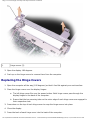
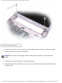
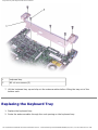
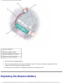
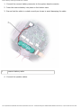
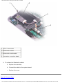
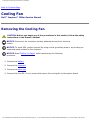
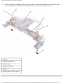
1
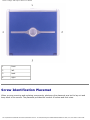
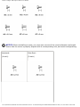
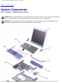
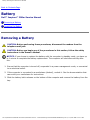
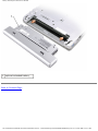
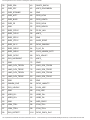
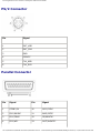
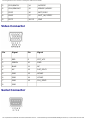
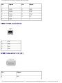
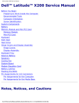
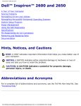
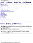
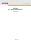
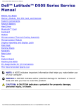
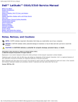
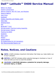
Thank you for purchasing this Factory Service
Manual CD/DVD from servicemanuals4u.com.
Please check out our eBay auctions for more great
deals on Factory Service Manuals:
servicemanuals4u
Dell Inspiron 300m Service Manual
Dell™ Inspiron™ 300m Service Manual
Before You Begin
Dell Diagnostics
System Components
Battery
Memory, Modem, and Mini PCI Card Modules
Keyboard
Palm Rest
Hard Drive
Hinge Covers and Display Assembly
Keyboard Tray
Reserve Battery
Speakers
Bluetooth™ Module
Cooling Fan
Battery Latches
System Board
Flashing the BIOS
Pin Assignments for I/O Connectors
Mini Recommended Spares List
Notes, Notices, and Cautions
NOTE: A NOTE indicates important information that helps you make better use of your
computer.
NOTICE: A NOTICE indicates either potential damage to hardware or loss of data and tells you
how to avoid the problem.
CAUTION: A CAUTION indicates a potential for property damage, personal injury, or
death.
Information in this document is subject to change without notice.
© 2003 Dell Inc. All rights reserved.
Reproduction in any manner whatsoever without the written permission of Dell Inc. is strictly forbidden.
file:///I|/SERVICE%20MANUALS/DELL%20MANUALS/LA...checked%20ok/Inspiron/300M/300M%20SM/index.htm (1 of 2)6/21/2004 12:22:27 AM
Dell Inspiron 300m Service Manual
Trademarks used in this text: Dell, the DELL logo, ExpressCharge, and Latitude are trademarks of Dell Inc.; Microsoft and
Windows are registered trademarks of Microsoft Corporation; Intel is a registered trademark of Intel Corporation; Bluetooth
is a trademark owned by Bluetooth SIG, Inc. and is used by Dell Inc. under license.
Other trademarks and trade names may be used in this document to refer to either the entities claiming the marks and
names or their products. Dell Inc. disclaims any proprietary interest in trademarks and trade names other than its own.
November 2003 Rev. A01
file:///I|/SERVICE%20MANUALS/DELL%20MANUALS/LA...checked%20ok/Inspiron/300M/300M%20SM/index.htm (2 of 2)6/21/2004 12:22:27 AM
Before You Begin: Dell Inspiron 300m Service Manual
Back to Contents Page
Before You Begin
Dell™ Inspiron™ 300m Service Manual
Recommended Tools
Shutting Down Your Computer
Computer Orientation
Screw Identification Placemat
This section provides procedures for removing and installing the components in your computer. Unless
otherwise noted, each procedure assumes that the following conditions exist:
●
You have performed the steps in "Shutting Down Your Computer."
●
You have read the safety information in your Owner's Manual.
Recommended Tools
The procedures in this document may require the following tools:
●
Small flat-blade screwdriver
●
Phillips screwdriver
●
Small plastic scribe
●
Flash BIOS update program floppy disk or CD
Shutting Down Your Computer
Use the following safety guidelines to help protect your computer from potential damage and to ensure
your own personal safety.
CAUTION: Before you begin any of the procedures in this section, follow the safety
instructions in the Owner's Manual.
file:///I|/SERVICE%20MANUALS/DELL%20MANUALS/LA...hecked%20ok/Inspiron/300M/300M%20SM/before.htm (1 of 7)6/21/2004 12:22:29 AM
Before You Begin: Dell Inspiron 300m Service Manual
NOTICE: Only a certified service technician should perform repairs on your computer. Damage
due to servicing that is not authorized by Dell is not covered by your warranty.
CAUTION: Handle components and cards with care. Do not touch the components or
contacts on a card. Hold a card by its edges or by its metal mounting bracket. Hold a
component such as a microprocessor by its edges, not by its pins.
NOTICE: When you disconnect a cable, pull on its connector or on its strain-relief loop, not on
the cable itself. Some cables have a connector with locking tabs; if you are disconnecting this
type of cable, press in on the locking tabs before you disconnect the cable. As you pull
connectors apart, keep them evenly aligned to avoid bending any connector pins. Also, before
you connect a cable, ensure that both connectors are correctly oriented and aligned.
NOTICE: To avoid damaging the computer, perform the following steps before you begin
working inside the computer.
1. Ensure that the work surface is flat and clean to prevent the computer cover from being
scratched.
2. Shut down the computer.
3. Ensure that the computer and any attached devices are turned off. If your computer and
attached devices did not automatically turn off when you shut down your computer, press and
hold the power button for 4 seconds.
4. If the computer is connected to a media base (docked), undock it. See the documentation that
came with your media base for instructions.
NOTICE: To disconnect a network cable, first unplug the cable from your computer and then
unplug it from the network wall jack.
5. Disconnect any telephone or telecommunication lines from the computer.
6. Disconnect your computer and all attached devices from their electrical outlets, and then press
the power button to ground the system board.
NOTICE: To connect a network cable, first plug the cable into the network wall jack and then
plug it into the computer.
7. Remove any installed PC Cards from the PC Card slot.
8. Remove any installed Secure Digital memory card from the Secure Digital memory slot.
9. Close the display and turn the computer upside down on a flat work surface.
NOTICE: To avoid damaging the system board, you must remove the main battery before you
service the computer.
10. Slide and hold the battery-bay latch release on the bottom of the computer, and then remove
file:///I|/SERVICE%20MANUALS/DELL%20MANUALS/LA...hecked%20ok/Inspiron/300M/300M%20SM/before.htm (2 of 7)6/21/2004 12:22:29 AM
Before You Begin: Dell Inspiron 300m Service Manual
the battery from the bay.
1
battery latch release (2)
11. Remove any installed modules, including a second battery, if installed.
12. Remove the hard drive.
Computer Orientation
file:///I|/SERVICE%20MANUALS/DELL%20MANUALS/LA...hecked%20ok/Inspiron/300M/300M%20SM/before.htm (3 of 7)6/21/2004 12:22:29 AM
Before You Begin: Dell Inspiron 300m Service Manual
1
front
2
left
3
back
4
right
Screw Identification Placemat
When you are removing and replacing components, photocopy the placemat as a tool to lay out and
keep track of the screws. The placemat provides the number of screws and their sizes.
file:///I|/SERVICE%20MANUALS/DELL%20MANUALS/LA...hecked%20ok/Inspiron/300M/300M%20SM/before.htm (4 of 7)6/21/2004 12:22:29 AM
Before You Begin: Dell Inspiron 300m Service Manual
NOTICE: When reinstalling a screw, you must use a screw of the correct diameter and length.
Ensure that the screw is properly aligned with its corresponding hole, and avoid overtightening.
Keyboard:
Palm Rest:
(4 each)
(9 each)
file:///I|/SERVICE%20MANUALS/DELL%20MANUALS/LA...hecked%20ok/Inspiron/300M/300M%20SM/before.htm (5 of 7)6/21/2004 12:22:29 AM
Before You Begin: Dell Inspiron 300m Service Manual
Display Assembly:
Keyboard Tray:
(2 each)
(5 each)
Hard Drive:
System Board:
(4 each)
(3 each)
Modem Card:
Cooling Fan:
(1 each)
(4 each)
file:///I|/SERVICE%20MANUALS/DELL%20MANUALS/LA...hecked%20ok/Inspiron/300M/300M%20SM/before.htm (6 of 7)6/21/2004 12:22:29 AM
Before You Begin: Dell Inspiron 300m Service Manual
Speakers:
Bluetooth™ Module
(1 each)
(1 each)
Back to Contents Page
file:///I|/SERVICE%20MANUALS/DELL%20MANUALS/LA...hecked%20ok/Inspiron/300M/300M%20SM/before.htm (7 of 7)6/21/2004 12:22:29 AM
Dell Diagnostics: Dell Inspiron 300m Service Manual
Back to Contents Page
Dell Diagnostics
Dell™ Inspiron™ 300m Service Manual
When to Use the Dell Diagnostics
Starting the Dell Diagnostics
When to Use the Dell Diagnostics
If you experience a problem with your computer, perform the checks in the "Solving Problems" section
in your User's Guide or Owner's Manual and run the Dell Diagnostics before you contact Dell for
technical assistance. Running the Dell Diagnostics may help you resolve the problem without
contacting Dell. If you do contact Dell, the test results can provide important information for Dell's
service and support personnel.
The Dell Diagnostics allows you to:
●
Perform tests on one or all devices.
●
Select tests based on a symptom of the problem you are having.
●
Choose how many times a test is run.
●
Suspend testing if an error is detected.
●
Access help information that describes the tests and devices.
●
Receive status messages that tell you whether tests completed successfully.
●
Receive error messages if problems are detected.
Starting the Dell Diagnostics
NOTICE: Use the Dell Diagnostics to test your Dell™ computer only. Using this program with
other computers can result in error messages.
The Dell Diagnostics is located on a hidden diagnostic utility partition on your hard drive.
file:///I|/SERVICE%20MANUALS/DELL%20MANUALS/LA..._checked%20ok/Inspiron/300M/300M%20SM/diag.htm (1 of 4)6/21/2004 12:22:29 AM
Dell Diagnostics: Dell Inspiron 300m Service Manual
NOTE: If your computer cannot display a screen image, contact
Dell.
1. Shut down the computer.
2. If the computer is connected to a media base (docked), undock it. See the documentation that
came with your media base for instructions.
3. Connect the computer to an electrical outlet.
4. Turn on the computer. When the DELL™ logo appears, press <F12>immediately.
NOTE: If you cannot see anything on your display, hold down the mute button and press the
computer's power button to begin the Dell Diagnostics. The computer automatically runs the
Pre-boot System Assessment.
NOTE: If you see a message stating that no diagnostics utility partition has been found, run the
Dell Diagnostics from your Drivers and Utilities CD.
If you wait too long and the Microsoft® Windows® logo appears, continue to wait until you see
the Windows desktop. Then shut down your computer through the Start menu and try again.
5. When the boot device list appears, highlight Diagnostics and press <Enter>.
The computer runs the Pre-boot System Assessment, a series of initial tests of your system
board, keyboard, hard drive, and display.
●
●
●
During the assessment, answer any questions that appear.
If a failure is detected, the computer stops and beeps. To stop the assessment and
restart the computer, press <N>; to continue to the next test, press <Y>; to retest the
component that failed, press <R>.
If failures are detected during the Pre-boot System Assessment, write down the error
code(s) and contact Dell before continuing on to the Dell Diagnostics.
If the Pre-boot System Assessment completes successfully, you receive the message Booting
Dell Diagnostic Utility Partition. Press any key to continue.
6. Press any key to start the Dell Diagnostics from the diagnostics utility partition on your hard
drive.
7. When the Dell Diagnostics Main Menu appears, select the test you want to run (see xx).
Dell Diagnostics Main Menu
1. After the Dell Diagnostics loads and the Main Menu screen appears, click the button for the
option you want.
file:///I|/SERVICE%20MANUALS/DELL%20MANUALS/LA..._checked%20ok/Inspiron/300M/300M%20SM/diag.htm (2 of 4)6/21/2004 12:22:29 AM
Dell Diagnostics: Dell Inspiron 300m Service Manual
Option
Function
Express Test
Performs a quick test of devices. This test typically takes 10 to 20 minutes and
requires no interaction on your part. Run Express Test first to increase the
possibility of tracing the problem quickly.
Extended Test
Performs a thorough check of devices. This test typically takes an hour or more and
requires you to answer questions periodically.
Custom Test
Tests a specific device. You can customize the tests you want to run.
Symptom Tree Lists the most common symptoms encountered and allows you to select a test
based on the symptom of the problem you are having.
2. If a problem is encountered during a test, a message appears with an error code and a
description of the problem. Write down the error code and problem description and follow the
instructions on the screen.
If you cannot resolve the error condition, contact Dell. See your User's Guide or Owner's Manual
for contact information.
NOTE: The Service Tag for your computer is located at the top of each test screen. If you
contact Dell, technical support will ask for your Service Tag.
3. If you run a test from the Custom Test or Symptom Tree option, click the applicable tab
described in the following table for more information.
Tab
Function
Results
Displays the results of the test and any error conditions encountered.
Errors
Displays error conditions encountered, error codes, and the problem description.
Help
Describes the test and may indicate requirements for running the test.
Configuration Displays your hardware configuration for the selected device.
The Dell Diagnostics obtains configuration information for all devices from the system
setup program, memory, and various internal tests, and it displays the information in
the device list in the left pane of the screen. The device list may not display the
names of all the components installed on your computer or all devices attached to
your computer.
Parameters
Allows you to customize the test by changing the test settings.
4. When the tests are complete, close the test screen to return to the Main Menu screen. To exit
file:///I|/SERVICE%20MANUALS/DELL%20MANUALS/LA..._checked%20ok/Inspiron/300M/300M%20SM/diag.htm (3 of 4)6/21/2004 12:22:29 AM
Dell Diagnostics: Dell Inspiron 300m Service Manual
the Dell Diagnostics and restart the computer, close the Main Menu screen.
Back to Contents Page
file:///I|/SERVICE%20MANUALS/DELL%20MANUALS/LA..._checked%20ok/Inspiron/300M/300M%20SM/diag.htm (4 of 4)6/21/2004 12:22:29 AM
System Components: Dell Inspiron 300m Service Manual
Back to Contents Page
System Components
Dell™ Inspiron™ 300m Service Manual
NOTICE: Only a certified service technician should perform repairs on your computer. Damage
due to servicing that is not authorized by Dell is not covered by your warranty.
NOTICE: Unless otherwise noted, each procedure in this manual assumes that a part can be
replaced by performing the removal procedure in reverse order.
file:///I|/SERVICE%20MANUALS/DELL%20MANUALS/LA...hecked%20ok/Inspiron/300M/300M%20SM/system.htm (1 of 2)6/21/2004 12:22:30 AM
System Components: Dell Inspiron 300m Service Manual
1 display
8
2 hinge covers (2) 9
speakers (2)
reserve battery
3 keyboard tray
10 Bluetooth™ module
4 battery
11 system board
5 cooling fan
12 palm rest
6 hard drive
13 keyboard
7 bottom case
Back to Contents Page
file:///I|/SERVICE%20MANUALS/DELL%20MANUALS/LA...hecked%20ok/Inspiron/300M/300M%20SM/system.htm (2 of 2)6/21/2004 12:22:30 AM
Battery: Dell Inspiron 300m Service Manual
Back to Contents Page
Battery
Dell™ Inspiron™ 300m Service Manual
Removing a Battery
Installing the Battery
Removing a Battery
CAUTION: Before performing these procedures, disconnect the modem from the
telephone wall jack.
CAUTION: Before you begin any of the procedures in this section, follow the safety
instructions in the Owner's Manual.
NOTICE: If you choose to replace the battery with the computer in standby mode, you have up
to 1 minute to complete the battery replacement. The computer will shut down shortly after
this.
1. Ensure that the computer is turned off, suspended in a power management mode, or connected
to an electrical outlet.
2. If the computer is connected to a media base (docked), undock it. See the documentation that
came with your media base for instructions.
3. Slide the battery latch releases on the bottom of the computer and remove the battery from the
bay.
file:///I|/SERVICE%20MANUALS/DELL%20MANUALS/LA...ecked%20ok/Inspiron/300M/300M%20SM/battery.htm (1 of 3)6/21/2004 12:22:31 AM
Battery: Dell Inspiron 300m Service Manual
1
battery latch release (2)
Installing the Battery
To install the battery, slide the battery or the optional extended battery into the bay until the latch
release clicks.
file:///I|/SERVICE%20MANUALS/DELL%20MANUALS/LA...ecked%20ok/Inspiron/300M/300M%20SM/battery.htm (2 of 3)6/21/2004 12:22:31 AM
Battery: Dell Inspiron 300m Service Manual
1
optional extended battery
Back to Contents Page
file:///I|/SERVICE%20MANUALS/DELL%20MANUALS/LA...ecked%20ok/Inspiron/300M/300M%20SM/battery.htm (3 of 3)6/21/2004 12:22:31 AM
Memory, Modem, and Mini PCI Card Modules: Dell Inspiron 300m Service Manual
Back to Contents Page
Memory, Modem, and Mini PCI Card Modules
Dell™ Inspiron™ 300m Service Manual
Adding Memory
Replacing a Modem
Adding a Mini PCI Card
Adding Memory
You can increase your computer memory by installing a memory module on the system board. See the
"Specifications" section in your Owner's Manual for information on the memory supported by your
computer. Be sure to add only a memory module that is intended for your computer.
NOTE: Memory modules purchased from Dell are covered under your computer
warranty.
CAUTION: Before you begin any of the procedures in this section, follow the safety
instructions in the Owner's Manual.
1. Ensure that the work surface is flat and clean to prevent scratching the computer cover.
2. Save and close any open files, exit any open programs, and shut down the computer.
3. If the computer is connected to the media base (docked), undock it. See the documentation
that came with your media base for instructions.
4. Disconnect the computer from the electrical outlet.
5. Wait 10 to 20 seconds, and then disconnect any attached devices.
6. Remove any installed PC Cards and battery.
NOTICE: Handle components and cards by their edges, and avoid touching pins and contacts.
Ground yourself by touching a metal connector on the back of the computer. Continue to
ground yourself periodically during this procedure.
7. Turn the computer over, unscrew both captive screw(s) from the memory module/Mini PCI/
modem cover, and remove the cover.
file:///I|/SERVICE%20MANUALS/DELL%20MANUALS/LA...cked%20ok/Inspiron/300M/300M%20SM/upgrades.htm (1 of 14)6/21/2004 12:22:34 AM
Memory, Modem, and Mini PCI Card Modules: Dell Inspiron 300m Service Manual
1
captive screw (2)
2
memory module cover
NOTICE: To prevent damage to the memory module connector, do not use tools to spread the
memory module securing clips.
8. If you are replacing a memory module, remove the existing module.
NOTICE: Handle components and cards by their edges, and avoid touching pins and contacts.
Ground yourself by touching a metal connector on the back of the computer. Continue to
ground yourself periodically during this procedure.
a. Use your fingertips to carefully spread apart the securing clips on each end of the
memory module connector until the module pops up.
b. Remove the module from the connector.
file:///I|/SERVICE%20MANUALS/DELL%20MANUALS/LA...cked%20ok/Inspiron/300M/300M%20SM/upgrades.htm (2 of 14)6/21/2004 12:22:34 AM
Memory, Modem, and Mini PCI Card Modules: Dell Inspiron 300m Service Manual
1
memory module
2
securing clips (2)
9. Ground yourself and install the new memory module:
a. Align the notch in the module edge connector with the tab in the center of the connector
slot.
b. Slide the module firmly into the slot at a 45-degree angle, and rotate the module down
until it clicks into place. If you do not hear the click, remove the module and reinstall it.
NOTE: If the memory module is not installed properly, the computer may not boot properly. No
error message indicates this failure.
file:///I|/SERVICE%20MANUALS/DELL%20MANUALS/LA...cked%20ok/Inspiron/300M/300M%20SM/upgrades.htm (3 of 14)6/21/2004 12:22:34 AM
Memory, Modem, and Mini PCI Card Modules: Dell Inspiron 300m Service Manual
1
memory module
2
connector
10. Replace the cover.
NOTICE: If the cover is difficult to close, remove the module and reinstall it. Forcing the cover
to close may damage your computer.
file:///I|/SERVICE%20MANUALS/DELL%20MANUALS/LA...cked%20ok/Inspiron/300M/300M%20SM/upgrades.htm (4 of 14)6/21/2004 12:22:34 AM
Memory, Modem, and Mini PCI Card Modules: Dell Inspiron 300m Service Manual
1
captive screw (2)
2
memory module cover
11. Insert the battery into the battery bay, or connect the AC adapter to your computer and an
electrical outlet.
12. Turn on the computer.
As the computer boots, it detects the additional memory and automatically updates the system
configuration information.
To confirm the amount of memory installed in the computer:
●
●
In the Microsoft® Windows® XP operating system, click the Start button, click Help and
Support, and then click Computer Information.
In Windows 2000, right-click the My Computer icon on your desktop, and then click the
General tab.
file:///I|/SERVICE%20MANUALS/DELL%20MANUALS/LA...cked%20ok/Inspiron/300M/300M%20SM/upgrades.htm (5 of 14)6/21/2004 12:22:34 AM
Memory, Modem, and Mini PCI Card Modules: Dell Inspiron 300m Service Manual
Replacing a Modem
CAUTION: Before performing any of the procedures listed below, read and follow the
safety instructions in the System Information Guide.
1. Ensure that the work surface is flat and clean to prevent scratching the computer cover.
2. Save and close any open files, exit any open programs, and then shut down the computer.
3. If the computer is connected to a media base (docked), undock it. See the documentation that
came with the media base for instructions.
4. Disconnect the computer from the electrical outlet.
5. Wait 10 to 20 seconds and then disconnect any attached devices.
6. Remove any installed PC Cards or blanks, battery, and devices.
NOTICE: Handle modules by their edges, and do not touch the components on a module.
Ground yourself by touching a metal connector on the back of the computer, and continue to
do so periodically during this procedure.
7. Turn the computer over and loosen the two captive screws on the modem cover, and remove
the cover.
file:///I|/SERVICE%20MANUALS/DELL%20MANUALS/LA...cked%20ok/Inspiron/300M/300M%20SM/upgrades.htm (6 of 14)6/21/2004 12:22:34 AM
Memory, Modem, and Mini PCI Card Modules: Dell Inspiron 300m Service Manual
1
captive screw (2)
2
cover
8. If a modem is not already installed, go to step 10.
9. If you are replacing a modem, remove the existing modem:
a. Remove the screw securing the modem to the system board, and set it aside.
b. Pull straight up on the attached pull-tab to lift the modem out of its connector on the
system board, and disconnect the modem cable.
file:///I|/SERVICE%20MANUALS/DELL%20MANUALS/LA...cked%20ok/Inspiron/300M/300M%20SM/upgrades.htm (7 of 14)6/21/2004 12:22:34 AM
Memory, Modem, and Mini PCI Card Modules: Dell Inspiron 300m Service Manual
1
modem cable connector
2
modem
3
modem screw
4
system board connector
10. Connect the modem cable to the modem.
NOTICE: The connectors are keyed to ensure correct insertion. If you feel resistance, check
the connectors and realign the card.
11. Align the modem with the screw hole and press the modem into the connector on the system
board.
12. Install the screw to secure the modem to the system board.
13. Replace the cover.
file:///I|/SERVICE%20MANUALS/DELL%20MANUALS/LA...cked%20ok/Inspiron/300M/300M%20SM/upgrades.htm (8 of 14)6/21/2004 12:22:34 AM
Memory, Modem, and Mini PCI Card Modules: Dell Inspiron 300m Service Manual
Adding a Mini PCI Card
If you ordered a Mini PCI card with your computer, the card is already installed.
CAUTION: Before performing any of the procedures listed below, read and follow the
safety instructions in the System Information Guide.
1. Ensure that the work surface is flat and clean to prevent scratching the computer cover.
2. Save and close any open files, exit any open programs, and shut down the computer.
3. If the computer is connected to a media base (docked), undock it. See the documentation that
came with the media base for instructions.
4. Disconnect the computer from the electrical outlet.
5. Wait 10 to 20 seconds and then disconnect any attached devices.
6. Remove any installed PC Card or blanks, battery, and devices.
NOTICE: Handle modules and cards by their edges, and avoid touching pins and contacts.
Ground yourself by touching a metal connector on the back of the computer. Continue to
ground yourself periodically during this procedure.
7. Turn the computer over, and loosen both the captive screw(s) from the Mini PCI card cover and
remove the cover.
file:///I|/SERVICE%20MANUALS/DELL%20MANUALS/LA...cked%20ok/Inspiron/300M/300M%20SM/upgrades.htm (9 of 14)6/21/2004 12:22:34 AM
Memory, Modem, and Mini PCI Card Modules: Dell Inspiron 300m Service Manual
1
captive screw (2)
2
cover
8. If a Mini PCI card is not already installed, go to step 10.
9. If you are replacing a Mini PCI card, remove the existing card:
a. Disconnect the Mini PCI card from the attached cables.
file:///I|/SERVICE%20MANUALS/DELL%20MANUALS/L...ked%20ok/Inspiron/300M/300M%20SM/upgrades.htm (10 of 14)6/21/2004 12:22:34 AM
Memory, Modem, and Mini PCI Card Modules: Dell Inspiron 300m Service Manual
1
cable connectors
b. Release the Mini PCI card by spreading the metal securing tabs until the card pops up
slightly.
file:///I|/SERVICE%20MANUALS/DELL%20MANUALS/L...ked%20ok/Inspiron/300M/300M%20SM/upgrades.htm (11 of 14)6/21/2004 12:22:34 AM
Memory, Modem, and Mini PCI Card Modules: Dell Inspiron 300m Service Manual
1
latch release
2
MPCI card
c. Lift the Mini PCI card out of its connector.
NOTICE: To avoid damaging the Mini PCI card, never place cables on top of or under the
card.
10. To replace a Mini PCI card, align the card with the connector at a 45-degree angle, and press
the Mini PCI card into the connector.
11. Lower the Mini PCI card toward the inner tabs to approximately a 20-degree angle.
12. Continue lowering the Mini PCI card until it snaps into the inner tabs of the connector.
file:///I|/SERVICE%20MANUALS/DELL%20MANUALS/L...ked%20ok/Inspiron/300M/300M%20SM/upgrades.htm (12 of 14)6/21/2004 12:22:34 AM
Memory, Modem, and Mini PCI Card Modules: Dell Inspiron 300m Service Manual
1
connector
2
Mini PCI card
13. Connect the antenna cable to the antenna connector on the Mini PCI card.
NOTICE: The connectors are keyed for correct insertion. If you feel resistance, check the
connectors and realign the card.
file:///I|/SERVICE%20MANUALS/DELL%20MANUALS/L...ked%20ok/Inspiron/300M/300M%20SM/upgrades.htm (13 of 14)6/21/2004 12:22:34 AM
Memory, Modem, and Mini PCI Card Modules: Dell Inspiron 300m Service Manual
1
cable connector
14. Replace the cover and tighten the screws.
Back to Contents Page
file:///I|/SERVICE%20MANUALS/DELL%20MANUALS/L...ked%20ok/Inspiron/300M/300M%20SM/upgrades.htm (14 of 14)6/21/2004 12:22:34 AM
Keyboard: Dell Inspiron 300m Service Manual
Back to Contents Page
Keyboard
Dell™ Inspiron™ 300m Service Manual
Removing the Keyboard
Replacing the Keyboard
Removing the Keyboard
CAUTION: Before you begin any of the procedures in this section, follow the safety
instructions in the Owner's Manual.
NOTICE: Disconnect the computer and any attached devices from electrical
outlets.
NOTICE: To avoid ESD, ground yourself by using a wrist grounding strap or by touching an
unpainted metal surface on the computer.
NOTICE: Read "Before You Begin" before performing the following
procedure.
1. Remove the battery.
2. Remove the four M2 x 4-mm screws labeled with an arrow from the bottom of the computer.
file:///I|/SERVICE%20MANUALS/DELL%20MANUALS/LA...cked%20ok/Inspiron/300M/300M%20SM/keyboard.htm (1 of 5)6/21/2004 12:22:35 AM
Keyboard: Dell Inspiron 300m Service Manual
1
M2 x 4-mm screws (4)
NOTICE: The keycaps on the keyboard are fragile, easily dislodged, and time-consuming to
replace. Be careful when removing and handling the keyboard.
3. Turn the computer over, and insert a ¼-inch flat-blade screwdriver into the slot to the right of
the keyboard locator tab.
file:///I|/SERVICE%20MANUALS/DELL%20MANUALS/LA...cked%20ok/Inspiron/300M/300M%20SM/keyboard.htm (2 of 5)6/21/2004 12:22:35 AM
Keyboard: Dell Inspiron 300m Service Manual
1
keyboard locator tab
4. Pry up the keyboard locator tab, and the keyboard pops up.
5. Pull the keyboard a small distance toward the front of the computer to release the four securing
tabs located across the back edge of the keyboard.
6. Rotate the keyboard toward the front of the computer and place it face-down on the palm rest.
NOTICE: Do not pull on the keyboard flex
cable.
7. Open the ZIF connector on the system board by pulling the ZIF connector tabs toward the back
of the computer.
file:///I|/SERVICE%20MANUALS/DELL%20MANUALS/LA...cked%20ok/Inspiron/300M/300M%20SM/keyboard.htm (3 of 5)6/21/2004 12:22:35 AM
Keyboard: Dell Inspiron 300m Service Manual
1
ZIF connector
2
keyboard flex cable
3
ZIF connector tabs (2)
8. Remove the keyboard flex cable from the ZIF connector.
9. Lift the keyboard up and out of the computer.
Replacing the Keyboard
1. Place the keyboard face-down on the palm rest, with the keyboard flex cable pointing toward
file:///I|/SERVICE%20MANUALS/DELL%20MANUALS/LA...cked%20ok/Inspiron/300M/300M%20SM/keyboard.htm (4 of 5)6/21/2004 12:22:35 AM
Keyboard: Dell Inspiron 300m Service Manual
the back of the computer.
NOTICE: To avoid damage to the connector pins, insert the keyboard flex cable evenly into the
ZIF connector on the system board, and do not reverse the keyboard flex cable.
2. Ensure that the ZIF connector is open by pulling the ZIF connector tabs toward the back of the
computer.
3. Press the keyboard flex cable into the ZIF connector.
4. Close the ZIF connector by pushing the ZIF connector tabs toward the front of the computer.
To aid with proper flex cable connection, a locator line has been added near the end of the flex
cable. Press the cable into the connector until the line disappears and hold the cable steady while
you close the ZIF connector. (The white line may reappear after the connector is closed, which
should not indicate a problem with the connection.)
NOTICE: Position the keyboard flex cable so that it is not pinched when you replace the
keyboard in the bottom case.
5. Rotate the keyboard back and fit it into the bottom case.
6. Ensure that all four keyboard securing tabs are engaged in their respective slots before trying to
completely seat the keyboard. Press down on the left and right <Alt> keys to help control tab/
slot alignment.
When the keyboard appears to be completely seated, confirm that the front edge of the keyboard
is aligned with the edge of the palm rest before proceeding.
7. Replace the four M2 x 4-mm screws on the bottom of the computer.
Back to Contents Page
file:///I|/SERVICE%20MANUALS/DELL%20MANUALS/LA...cked%20ok/Inspiron/300M/300M%20SM/keyboard.htm (5 of 5)6/21/2004 12:22:35 AM
Palm Rest: Dell Inspiron 300m Service Manual
Back to Contents Page
Palm Rest
Dell™ Inspiron™ 300m Service Manual
Removing the Palm Rest
Replacing the Palm Rest
Removing the Palm Rest
CAUTION: Before you begin any of the procedures in this section, follow the safety
instructions in the Owner's Manual.
NOTICE: Disconnect the computer and any attached devices from electrical
outlets.
NOTICE: To avoid ESD, ground yourself by using a wrist grounding strap or by touching an
unpainted metal surface on the computer.
NOTICE: Read "Before You Begin" before performing the following
procedure.
1. Remove the battery.
2. Remove the keyboard.
3. Turn the computer over, and remove the three M2 x 4-mm screws from the bottom of the
computer.
file:///I|/SERVICE%20MANUALS/DELL%20MANUALS/LA...cked%20ok/Inspiron/300M/300M%20SM/palmrest.htm (1 of 5)6/21/2004 12:22:36 AM
Palm Rest: Dell Inspiron 300m Service Manual
1
M2X4 screw (3)
4. Turn the computer over, and open the display.
5. Remove the six M2 x 4-mm screws on the palm rest.
file:///I|/SERVICE%20MANUALS/DELL%20MANUALS/LA...cked%20ok/Inspiron/300M/300M%20SM/palmrest.htm (2 of 5)6/21/2004 12:22:36 AM
Palm Rest: Dell Inspiron 300m Service Manual
1
M2 x 4-mm screws (6)
6. Lift up and rotate the palm rest forward.
7. Lift the ZIF connector, and disconnect the palm-rest flex cable from its ZIF connector on the
system board.
file:///I|/SERVICE%20MANUALS/DELL%20MANUALS/LA...cked%20ok/Inspiron/300M/300M%20SM/palmrest.htm (3 of 5)6/21/2004 12:22:36 AM
Palm Rest: Dell Inspiron 300m Service Manual
1
palm rest flex cable
2
ZIF connector
3
palm rest
8. Lift the palm rest up and out of the computer.
Replacing the Palm Rest
To aid with proper flex cable connection, a locator line has been added near the end of the palm-rest
flex cable. When replacing the palm-rest flex cable, press the cable into the connector until the line
aligns with the system board and hold it steady while you snap the ZIF connector down. (The locator
line may reappear after the connector is closed, which should not indicate a problem with the
connection.)
file:///I|/SERVICE%20MANUALS/DELL%20MANUALS/LA...cked%20ok/Inspiron/300M/300M%20SM/palmrest.htm (4 of 5)6/21/2004 12:22:36 AM
Palm Rest: Dell Inspiron 300m Service Manual
Back to Contents Page
file:///I|/SERVICE%20MANUALS/DELL%20MANUALS/LA...cked%20ok/Inspiron/300M/300M%20SM/palmrest.htm (5 of 5)6/21/2004 12:22:36 AM
Hard Drive: Dell Inspiron 300m Service Manual
Back to Contents Page
Hard Drive
Dell™ Inspiron™ 300m Service Manual
Removing the Hard Drive
Replacing the Hard Drive
Removing the Hard Drive
CAUTION: Before you begin any of the procedures in this section, follow the safety
instructions in the Owner's Manual.
NOTICE: Disconnect the computer and any attached devices from electrical
outlets.
NOTICE: To avoid ESD, ground yourself by using a wrist grounding strap or by touching an
unpainted metal surface on the computer.
NOTICE: Read "Before You Begin" before performing the following
procedure.
1. Remove the battery.
2. Remove the keyboard.
3. Remove the palm rest.
4. Loosen the four M2 x 5.5-mm screws that secure the hard drive to the bottom case.
Rubber grommets secure each screw to the hard drive so that you do not need to completely
remove the screws.
file:///I|/SERVICE%20MANUALS/DELL%20MANUALS/LA...S_checked%20ok/Inspiron/300M/300M%20SM/hdd.htm (1 of 3)6/21/2004 12:22:38 AM
Hard Drive: Dell Inspiron 300m Service Manual
1
hard drive connector
2
hard drive
3
M2 x 5.5-mm screws (4)
5. Disconnect the hard drive connector from the system board.
6. Lift the hard drive up and out of the bottom case.
Replacing the Hard Drive
1. Connect the hard drive connector to the system board.
2. Position the hard drive on the bottom case and tighten the four M2 x 5.5-mm screws to the
file:///I|/SERVICE%20MANUALS/DELL%20MANUALS/LA...S_checked%20ok/Inspiron/300M/300M%20SM/hdd.htm (2 of 3)6/21/2004 12:22:38 AM
Hard Drive: Dell Inspiron 300m Service Manual
bottom case.
NOTE: The rubber grommets help you avoid overtightening the
screws.
Back to Contents Page
file:///I|/SERVICE%20MANUALS/DELL%20MANUALS/LA...S_checked%20ok/Inspiron/300M/300M%20SM/hdd.htm (3 of 3)6/21/2004 12:22:38 AM
Hinge Covers and Display Assembly: Dell Inspiron 300m Service Manual
Back to Contents Page
Hinge Covers and Display Assembly
Dell™ Inspiron™ 300m Service Manual
Hinge Covers
Display Assembly
Hinge Covers
Removing the Hinge Covers
CAUTION: Before you begin any of the procedures in this section, follow the safety
instructions in the Owner's Manual.
1. Remove the battery.
2. On the inside of the battery bay, use your fingers to unhook the hinge covers from the back of
the computer.
file:///I|/SERVICE%20MANUALS/DELL%20MANUALS/LA...ecked%20ok/Inspiron/300M/300M%20SM/display.htm (1 of 7)6/21/2004 12:22:39 AM
Hinge Covers and Display Assembly: Dell Inspiron 300m Service Manual
1
hinge covers (2)
3. Open the display 180 degrees.
4. Push up on the hinge covers to remove them from the computer.
Replacing the Hinge Covers
1. Open the computer all the way (180 degrees) so that it lies flat against your work surface.
2. Place the hinge covers over the display hinges:
a. The left hinge cover fits over the power button. Both hinge covers pass through the
display hinges to the back of the computer.
b. Ensure that the two securing tabs on the outer edge of each hinge cover are engaged in
their respective slots.
3. Press down on the top of each hinge cover to snap the hinge covers into place.
4. Close the display.
5. Press the back of each hinge cover into the back of the computer.
file:///I|/SERVICE%20MANUALS/DELL%20MANUALS/LA...ecked%20ok/Inspiron/300M/300M%20SM/display.htm (2 of 7)6/21/2004 12:22:39 AM
Hinge Covers and Display Assembly: Dell Inspiron 300m Service Manual
NOTE: The back of each hinge cover has a tab that snaps into a slot on the back of the
computer.
Display Assembly
Removing the Display Assembly
CAUTION: Before you begin any of the procedures in this section, follow the safety
instructions in the Owner's Manual.
NOTICE: Disconnect the computer and any attached devices from electrical
outlets.
NOTICE: To avoid ESD, ground yourself by using a wrist grounding strap or by touching an
unpainted metal surface on the computer.
NOTICE: Read "Before You Begin" before performing the following
procedure.
1. Remove the battery.
2. Remove the keyboard.
3. Turn the computer over, and remove the two M3 x 5-mm screws from the bottom of the
computer.
file:///I|/SERVICE%20MANUALS/DELL%20MANUALS/LA...ecked%20ok/Inspiron/300M/300M%20SM/display.htm (3 of 7)6/21/2004 12:22:39 AM
Hinge Covers and Display Assembly: Dell Inspiron 300m Service Manual
1
M3 x 5-mm screws (2)
4. Turn the computer over and open the display 180 degrees.
file:///I|/SERVICE%20MANUALS/DELL%20MANUALS/LA...ecked%20ok/Inspiron/300M/300M%20SM/display.htm (4 of 7)6/21/2004 12:22:39 AM
Hinge Covers and Display Assembly: Dell Inspiron 300m Service Manual
1
M2 x 6-mm screws (2)
5. Remove the two M2 x 6-mm screws near the display hinges on the top of the computer.
6. Disconnect both the antenna connectors.
NOTICE: Do not pull on the signal cable. Pull the signal connector to disconnect the
cables.
7. Disconnect the signal cable from the system board.
8. If a tape secures the signal connector, remove it and disconnect the signal cable from the
system board.
file:///I|/SERVICE%20MANUALS/DELL%20MANUALS/LA...ecked%20ok/Inspiron/300M/300M%20SM/display.htm (5 of 7)6/21/2004 12:22:39 AM
Hinge Covers and Display Assembly: Dell Inspiron 300m Service Manual
1
antenna connector
2
signal cable
3
signal connector
9. Remove the display assembly out of the bottom case.
Replacing the Display
1. Replace the display assembly into the bottom case and open the display 180 degrees.
2. Replace the two M2 x 6-mm screws by the display hinges on the top of the computer.
3. Connect both the antenna connectors, matching the color codes.
4. Connect the signal cable to the system board.
file:///I|/SERVICE%20MANUALS/DELL%20MANUALS/LA...ecked%20ok/Inspiron/300M/300M%20SM/display.htm (6 of 7)6/21/2004 12:22:39 AM
Hinge Covers and Display Assembly: Dell Inspiron 300m Service Manual
5. If a tape secured the signal connector, replace it and connect the signal cable to the system
board.
6. Close the display and turn the computer over.
7. Replace the two M3 x 5-mm screws from the bottom of the computer.
8. Replace the keyboard.
9. Replace the battery.
Back to Contents Page
file:///I|/SERVICE%20MANUALS/DELL%20MANUALS/LA...ecked%20ok/Inspiron/300M/300M%20SM/display.htm (7 of 7)6/21/2004 12:22:39 AM
Keyboard Tray: Dell Inspiron 300m Service Manual
Back to Contents Page
Keyboard Tray
Dell™ Inspiron™ 300m Service Manual
Removing the Keyboard Tray
Replacing the Keyboard Tray
Removing the Keyboard Tray
CAUTION: Before you begin any of the procedures in this section, follow the safety
instructions in the Owner's Manual.
NOTICE: Disconnect the computer and any attached devices from electrical
outlets.
NOTICE: To avoid ESD, ground yourself by using a wrist grounding strap or by touching an
unpainted metal surface on the computer.
NOTICE: Read "Before You Begin" before performing the following
procedure.
1. Remove the battery.
2. Remove the keyboard.
3. Remove the palm rest.
4. Remove the hinge covers.
5. Remove the display assembly.
6. Remove the five M2 x 4-mm screws that secure the keyboard tray to the system board.
NOTE: Each keyboard tray screw has an arrow beside
it.
file:///I|/SERVICE%20MANUALS/DELL%20MANUALS/LA...ecked%20ok/Inspiron/300M/300M%20SM/keytray.htm (1 of 3)6/21/2004 12:22:41 AM
Keyboard Tray: Dell Inspiron 300m Service Manual
1
keyboard tray
2
M2 x 4-mm screws (5)
7. Lift the keyboard tray up and slip out the antenna cables before lifting the tray out of the
bottom case.
Replacing the Keyboard Tray
1. Replace the keyboard tray.
2. Route the antenna cables through the oval opening on the keyboard tray.
file:///I|/SERVICE%20MANUALS/DELL%20MANUALS/LA...ecked%20ok/Inspiron/300M/300M%20SM/keytray.htm (2 of 3)6/21/2004 12:22:41 AM
Keyboard Tray: Dell Inspiron 300m Service Manual
1
antenna cable connectors
2
oval opening on keyboard tray
3. Reinstall the five M2 x 4-mm screws that secure the keyboard tray to the system board.
Back to Contents Page
file:///I|/SERVICE%20MANUALS/DELL%20MANUALS/LA...ecked%20ok/Inspiron/300M/300M%20SM/keytray.htm (3 of 3)6/21/2004 12:22:41 AM
Reserve Battery: Dell Inspiron 300m Service Manual
Back to Contents Page
Reserve Battery
Dell™ Inspiron™ 300m Service Manual
Removing the Reserve Battery
Replacing the Reserve Battery
Removing the Reserve Battery
CAUTION: Before you begin any of the procedures in this section, follow the safety
instructions in the Owner's Manual.
NOTICE: Disconnect the computer and any attached devices from electrical
outlets.
NOTICE: To avoid ESD, ground yourself by using a wrist grounding strap or by touching an
unpainted metal surface on the computer.
NOTICE: Read "Before You Begin" before performing the following
procedure.
1. Remove the battery.
2. Remove the keyboard.
3. Remove the palm rest.
NOTICE: Do not pull on the reserve battery cable. Pull from the reserve battery connector to
disconnect the cable.
4. Disconnect the reserve battery cable from the system board connector.
file:///I|/SERVICE%20MANUALS/DELL%20MANUALS/LAP...ecked%20ok/Inspiron/300M/300M%20SM/rsrvbatt.htm (1 of 4)6/21/2004 12:22:42 AM
Reserve Battery: Dell Inspiron 300m Service Manual
1
reserve battery
2
reserve battery cable
3
reserve battery connector
4
system board connector
5. Disconnect the speaker cables.
6. Pry the reserve battery free from the bottom case. The reserve battery is attached to the
bottom case with a piece of adhesive tape.
7. Remove any remnants of the adhesive tape from the bottom case.
Replacing the Reserve Battery
file:///I|/SERVICE%20MANUALS/DELL%20MANUALS/LAP...ecked%20ok/Inspiron/300M/300M%20SM/rsrvbatt.htm (2 of 4)6/21/2004 12:22:42 AM
Reserve Battery: Dell Inspiron 300m Service Manual
1. Connect the reserve battery connector to the system board connector.
2. Press the reserve battery into place on the bottom case.
3. Ensure that the cable is routed correctly as shown to avoid damaging the cable.
1
reserve battery cable
4. Connect the speaker cables.
file:///I|/SERVICE%20MANUALS/DELL%20MANUALS/LAP...ecked%20ok/Inspiron/300M/300M%20SM/rsrvbatt.htm (3 of 4)6/21/2004 12:22:42 AM
Reserve Battery: Dell Inspiron 300m Service Manual
1
speaker cables
2
speakers
5. Update the CMOS settings.
Back to Contents Page
file:///I|/SERVICE%20MANUALS/DELL%20MANUALS/LAP...ecked%20ok/Inspiron/300M/300M%20SM/rsrvbatt.htm (4 of 4)6/21/2004 12:22:42 AM
Speakers: Dell Inspiron 300m Service Manual
Back to Contents Page
Speakers
Dell™ Inspiron™ 300m Service Manual
Removing the Speakers
CAUTION: Before you begin any of the procedures in this section, follow the safety
instructions in the Owner's Manual.
NOTICE: Disconnect the computer and any attached devices from electrical
outlets.
NOTICE: To avoid ESD, ground yourself by using a wrist grounding strap or by touching an
unpainted metal surface on the computer.
NOTICE: Read "Before You Begin" before performing the following
procedure.
1. Remove the battery.
2. Remove the keyboard.
3. Remove the palm rest.
4. Remove the M2 x 4-mm screw that secures the speaker to the bottom case.
NOTE: The left and right speakers are
interchangeable.
file:///I|/SERVICE%20MANUALS/DELL%20MANUALS/LA...cked%20ok/Inspiron/300M/300M%20SM/speakers.htm (1 of 3)6/21/2004 12:22:42 AM
Speakers: Dell Inspiron 300m Service Manual
1
system board connector
(1 per speaker)
2
speaker connector
(1 per speaker)
3
M2 x 4-mm screw
(1 per speaker)
4
speaker cable
(1 per speaker)
5
speakers (2)
NOTICE: Do not pull on the speaker cable. Pull from the speaker connector to disconnect the
cable.
5. Disconnect the speaker cable from the system board connector.
NOTICE: Handle the speakers with care to avoid damaging
them.
6. Remove the speaker by pulling it straight up and out of the bottom case.
file:///I|/SERVICE%20MANUALS/DELL%20MANUALS/LA...cked%20ok/Inspiron/300M/300M%20SM/speakers.htm (2 of 3)6/21/2004 12:22:42 AM
Speakers: Dell Inspiron 300m Service Manual
Back to Contents Page
file:///I|/SERVICE%20MANUALS/DELL%20MANUALS/LA...cked%20ok/Inspiron/300M/300M%20SM/speakers.htm (3 of 3)6/21/2004 12:22:42 AM
Bluetooth™ Module: Dell Inspiron 300m Service Manual
Back to Contents Page
Bluetooth™ Module
Dell™ Inspiron™ 300m Service Manual
Replacing the Bluetooth Module
CAUTION: Before you begin any of the procedures in this section, follow the safety
instructions in the Owner's Manual.
1. Remove the M2 x 5-mm screw.
2. Disconnect the cable from the system board.
3. Lift the assembly out.
file:///I|/SERVICE%20MANUALS/DELL%20MANUALS/LA...cked%20ok/Inspiron/300M/300M%20SM/bluetoot.htm (1 of 3)6/21/2004 12:22:43 AM
Bluetooth™ Module: Dell Inspiron 300m Service Manual
1
M2 x 5-mm screw
2
Bluetooth module
3
Bluetooth module cable
4
connector on system board
4. To replace the Bluetooth module:
a. Replace the assembly.
b. Connect the cable to the system board.
c. Replace the screw.
Back to Contents Page
file:///I|/SERVICE%20MANUALS/DELL%20MANUALS/LA...cked%20ok/Inspiron/300M/300M%20SM/bluetoot.htm (2 of 3)6/21/2004 12:22:43 AM
Bluetooth™ Module: Dell Inspiron 300m Service Manual
file:///I|/SERVICE%20MANUALS/DELL%20MANUALS/LA...cked%20ok/Inspiron/300M/300M%20SM/bluetoot.htm (3 of 3)6/21/2004 12:22:43 AM
Cooling Fan: Dell Inspiron 300m Service Manual
Back to Contents Page
Cooling Fan
Dell™ Inspiron™ 300m Service Manual
Removing the Cooling Fan
CAUTION: Before you begin any of the procedures in this section, follow the safety
instructions in the Owner's Manual.
NOTICE: Disconnect the computer and any attached devices from electrical
outlets.
NOTICE: To avoid ESD, ground yourself by using a wrist grounding strap or by touching an
unpainted metal surface on the computer.
NOTICE: Read "Before You Begin" before performing the following
procedure.
1. Remove the battery.
2. Remove the keyboard.
3. Remove the palm rest.
4. Remove the four M2 x 3-mm screws that secure the cooling fan to the system board.
file:///I|/SERVICE%20MANUALS/DELL%20MANUALS/LA...S_checked%20ok/Inspiron/300M/300M%20SM/fan.htm (1 of 3)6/21/2004 12:22:44 AM
Cooling Fan: Dell Inspiron 300m Service Manual
1
M2 x 3-mm screws (4)
2
cooling fan
3
cooling fan cable
4
cooling fan connector
5
system board connector
5. Remove the tape that secures the cooling fan cable to the fan.
NOTICE: Do not pull on the cooling fan cable. Pull from the cooling fan connector to disconnect
the cable.
6. Disconnect the cooling fan cable from the system board connector.
file:///I|/SERVICE%20MANUALS/DELL%20MANUALS/LA...S_checked%20ok/Inspiron/300M/300M%20SM/fan.htm (2 of 3)6/21/2004 12:22:44 AM
Cooling Fan: Dell Inspiron 300m Service Manual
7. Lift the cooling fan up and out of the bottom case.
Back to Contents Page
file:///I|/SERVICE%20MANUALS/DELL%20MANUALS/LA...S_checked%20ok/Inspiron/300M/300M%20SM/fan.htm (3 of 3)6/21/2004 12:22:44 AM
Battery Latches: Dell Inspiron 300m Service Manual
Back to Contents Page
Battery Latches
Dell™ Inspiron™ 300m Service Manual
Removing the Battery Latches
Replacing the Battery Latches
Removing the Battery Latches
CAUTION: Before you begin any of the procedures in this section, follow the safety
instructions in the Owner's Manual.
NOTICE: Disconnect the computer and any attached devices from electrical
outlets.
NOTICE: To avoid ESD, ground yourself by using a wrist grounding strap or by touching an
unpainted metal surface on the computer.
NOTICE: Read "Before You Begin" before performing the following
procedure.
1. Remove the battery.
2. Remove the keyboard.
3. Remove the palm rest.
4. Remove the hinge covers.
5. Remove the display assembly.
6. Remove the keyboard tray.
7. Remove the hard drive.
8. Remove the memory module.
9. Remove the Mini PCI card, if present.
10. Remove the modem card, if present.
11. Remove the system board.
file:///I|/SERVICE%20MANUALS/DELL%20MANUALS/LAP...ecked%20ok/Inspiron/300M/300M%20SM/batlatch.htm (1 of 3)6/21/2004 12:22:45 AM
Battery Latches: Dell Inspiron 300m Service Manual
12. On the inside of the bottom case, use your fingers to unhook the latch from the bottom case
and the snap tabs, catching the latch button on the outside of the bottom case.
1 spring
2 battery lock latch
3 bottom case
4 battery lock latch
5 spring
6 battery-latch release button
file:///I|/SERVICE%20MANUALS/DELL%20MANUALS/LAP...ecked%20ok/Inspiron/300M/300M%20SM/batlatch.htm (2 of 3)6/21/2004 12:22:45 AM
Battery Latches: Dell Inspiron 300m Service Manual
Replacing the Battery Latches
1. Snap in the new latch button from behind the bottom case, making certain that the snap tabs
are fully engaged in the latch.
NOTE: The battery latch release has springs and should be installed on the bottom
case.
2. Ensure that the newly installed latch moves smoothly and freely when pushed and released.
Back to Contents Page
file:///I|/SERVICE%20MANUALS/DELL%20MANUALS/LAP...ecked%20ok/Inspiron/300M/300M%20SM/batlatch.htm (3 of 3)6/21/2004 12:22:45 AM
System Board: Dell Inspiron 300m Service Manual
Back to Contents Page
System Board
Dell™ Inspiron™ 300m Service Manual
Removing the System Board
Replacing the System Board
Removing the System Board
CAUTION: Before you begin any of the procedures in this section, follow the safety
instructions in the Owner's Manual.
NOTICE: Disconnect the computer and any attached devices from electrical
outlets.
NOTICE: To avoid ESD, ground yourself by using a wrist grounding strap or by touching an
unpainted metal surface on the computer.
NOTICE: Read "Before You Begin" before performing the following
procedure.
1. Remove the battery.
2. Remove the keyboard.
3. Remove the palm rest.
4. Remove the hinge covers.
5. Remove the display assembly.
6. Remove the keyboard tray.
7. Remove the hard drive.
8. Remove the memory module.
9. Remove the Mini PCI card, if present.
10. Remove the modem card, if present.
11. Remove the three M2 x 4-mm screws that secure the system board to the bottom case.
file:///I|/SERVICE%20MANUALS/DELL%20MANUALS/LA...cked%20ok/Inspiron/300M/300M%20SM/sysboard.htm (1 of 4)6/21/2004 12:22:46 AM
System Board: Dell Inspiron 300m Service Manual
NOTE: Each system board screw has an arrow beside
it.
1
system board
2
M2 x 4-mm screws (3)
3
status light (LED) cable
4
ZIF connector
12. Disconnect the left and right speakers from their system board connectors.
13. Disconnect the reserve battery connector from the system board connector.
14. Disconnect the Bluetooth cable from the system board, if a Bluetooth™ device is present.
file:///I|/SERVICE%20MANUALS/DELL%20MANUALS/LA...cked%20ok/Inspiron/300M/300M%20SM/sysboard.htm (2 of 4)6/21/2004 12:22:46 AM
System Board: Dell Inspiron 300m Service Manual
15. Lift the ZIF connector, and remove the status light (LED) cable from its ZIF connector on the
system board.
16. Lift the system board up, from the right side, and out of the bottom case.
Replacing the System Board
1. Place the system board in the bottom case.
NOTE: Route cables so that they will not be crimped or pinched when the complete assembly is
put back together.
1
wireless antenna
2. Reconnect all the cables to the system board ZIF connectors.
3. Reinstall the three M2 x 4-mm screws that secure the system board to the bottom case.
file:///I|/SERVICE%20MANUALS/DELL%20MANUALS/LA...cked%20ok/Inspiron/300M/300M%20SM/sysboard.htm (3 of 4)6/21/2004 12:22:46 AM
System Board: Dell Inspiron 300m Service Manual
NOTE: After replacing the system board, enter the computer Service Tag into the BIOS of the
replacement system board.
Back to Contents Page
file:///I|/SERVICE%20MANUALS/DELL%20MANUALS/LA...cked%20ok/Inspiron/300M/300M%20SM/sysboard.htm (4 of 4)6/21/2004 12:22:46 AM
Flashing the BIOS: Dell Inspiron 300m Service Manual
Back to Contents Page
Flashing the BIOS
Dell™ Inspiron™ 300m Service Manual
To update the basic input/output system (BIOS):
1. Go to support.dell.com. If this is your first time to use the website, complete the
one-time registration.
2. Enter the Service Tag for your computer or select the appropriate Dell™ computer.
Click Go.
3. Click Downloads.
4. Select the appropriate operating system and language for your computer.
5. Select the FlashBIOS Updates download category.
Click Go.
6. Click the BIOS link and follow the instructions to download the BIOS to your computer.
Back to Contents Page
file:///I|/SERVICE%20MANUALS/DELL%20MANUALS/LAPTOPS_checked%20ok/Inspiron/300M/300M%20SM/bios.htm6/21/2004 12:22:46 AM
Pin Assignments for I/O Connectors: Dell Inspiron 300m Service Manual
Back to Contents Page
Pin Assignments for I/O Connectors
Dell™ Inspiron™ 300m Service Manual
Pin Assignments for the Computer
Pin Assignments for the Media Base
Pin Assignments for the Computer
USB Connector 2.0
Pin
Signal
1
VCC
2
Data–
3
Data+
4
GND
Video Connector
file:///I|/SERVICE%20MANUALS/DELL%20MANUALS/LA...ecked%20ok/Inspiron/300M/300M%20SM/pinouts.htm (1 of 8)6/21/2004 12:22:48 AM
Pin Assignments for I/O Connectors: Dell Inspiron 300m Service Manual
Pin
Signal
Pin
Signal
1
RED
9
CRT_VCC
2
GREEN
10
GND
3
BLUE
11
NC
4
NC
12
DAT_DDC2
5
GND
13
HSYNC
6
GND
14
VSYNC
7
GND
15
CLK_DDC2
8
GND
IEEE 1394 Connector
1
TPB–
2
TPB+
3
TPA–
4
TPA+
file:///I|/SERVICE%20MANUALS/DELL%20MANUALS/LA...ecked%20ok/Inspiron/300M/300M%20SM/pinouts.htm (2 of 8)6/21/2004 12:22:48 AM
Pin Assignments for I/O Connectors: Dell Inspiron 300m Service Manual
Pin Assignments for the Media Base
Docking Connector
Pin
Signal
Pin
Signal
1
DCK3_DOCK_IN2*
2
USB3_P2+
3
SYS_DCIN*
4
USB3_P2–
5
VDC
6
GND
7
VDC
8
VGA3_RED
9
VDC
10
VGA3_GREEN
11
KBC3_ADID_CLK
12
VGA3_BLUE
13
GND
14
VGA5_DDCD
15
PIO3_SLCT
16
VGA5_DDCC
17
PIO3_AUTOFD*
18
VGA5_HSYNC
19
PIO3_ERROR*
20
VGA5_VSYNC
21
PIO3_INIT*
22
GND
23
PIO3_SLCTIN*
24
KBC3_EJECT*
25
GND
26
DCK3_RST*
27
PIO3_PD0
28
BATTB_PRES*
29
PIO3_PD1
30
BAT3_VOLTB
31
PIO3_PD2
32
KBC3_CHGENB
33
PIO3_PD3
34
KBC3_DCHGENB
35
PIO3_PD4
36
DCHGOUTB
37
PIO3_PD5
38
DBAT3_SMDATA
file:///I|/SERVICE%20MANUALS/DELL%20MANUALS/LA...ecked%20ok/Inspiron/300M/300M%20SM/pinouts.htm (3 of 8)6/21/2004 12:22:48 AM
Pin Assignments for I/O Connectors: Dell Inspiron 300m Service Manual
39
PIO3_PD6
40
DBAT3_SMCLK
41
PIO3_PD7
42
KBC3_DCKPWRON
43
PIO3_STROBE*
44
GND
45
PIO3_ACT*
46
PS25_KCLK
47
PIO3_BUSY
48
PS25_KDATA
49
PIO3_PE
50
PS25_MCLK
51
GND
52
PS25_MDATA
53
SIO3_DTR1*
54
P2.5V_LAN
55
SIO3_TXD1*
56
KBC3_
57
SIO3_RTS1*
58
GND
59
SIO3_CTS1*
60
AUD3_SPDIF
61
SIO3_R11*
62
DCK3_PWRSW*
63
SIO3_DSR1*
64
D_HP_IN
65
SIO3_DSR1*
66
CHP3_USBIDE_RST*
67
SIO3_DCD1*
68
DCK_VOLUP*
69
DCK_NICOMVDC
70
KBC3_
71
GND
72
GND*
73
LAN3_DCK_TRD2N
74
LAN3_DCK_TRD3N
75
LAN3_DCK_TRD2P
76
LAN3_DCK_TRD3P
77
LAN3_DCK_TRD0N
78
LAN3_DCK_TRD1N
79
LAN3_DCK_TRD0P
80
LAN3_DCK_TRD1P
81
GND
82
GND
83
PWRON_CHG
84
DCK3_LANACT*
85
DCK_VOLDN*
86
100M_LED*
87
GND
88
10M_LED*
89
USB3_P6–
90
USB3_P4+
91
USB3_P6+
92
USB3_P4–
93
GND
94
MOD_PRES*
95
1394_TPB–
96
1394_TPA–
97
1394_TPB+
98
1394_TPA+
99
DCK_DETECT*
100
DCK3_DOCK_IN1*
file:///I|/SERVICE%20MANUALS/DELL%20MANUALS/LA...ecked%20ok/Inspiron/300M/300M%20SM/pinouts.htm (4 of 8)6/21/2004 12:22:48 AM
Pin Assignments for I/O Connectors: Dell Inspiron 300m Service Manual
PS/2 Connector
Pin
Signal
1
DAT_KBD
2
DAT_SM1
3
GND
4
PS2VCC
5
CLK_KBD
6
CLK_SM1
Parallel Connector
Pin
Signal
Pin
Signal
1
STRB*/5V
10
ACK*/DRV*
2
PD0/INDEX*
11
BUSY/MTR*
3
PD1/TRK0*
12
PE/WDATA*
4
PD2/WP*
13
SLCT/WGATE*
file:///I|/SERVICE%20MANUALS/DELL%20MANUALS/LA...ecked%20ok/Inspiron/300M/300M%20SM/pinouts.htm (5 of 8)6/21/2004 12:22:48 AM
Pin Assignments for I/O Connectors: Dell Inspiron 300m Service Manual
5
PD3/RDATA*
14
AUTOFD*
6
PD4/DSKCHG*
15
ERROR*/HDSEL*
7
PD5F
16
INIT*/DIR*
8
PD6F
17
SLCT_IN/*STEP*
9
PD7F
18–25
GND
Video Connector
Pin
Signal
Pin
Signal
1
RED
9
CRT_VCC
2
GREEN
10
GND
3
BLUE
11
NC
4
NC
12
DAT_DDC2
5
GND
13
HSYNC
6
GND
14
VSYNC
7
GND
15
CLK_DDC2
8
GND
Serial Connector
file:///I|/SERVICE%20MANUALS/DELL%20MANUALS/LA...ecked%20ok/Inspiron/300M/300M%20SM/pinouts.htm (6 of 8)6/21/2004 12:22:48 AM
Pin Assignments for I/O Connectors: Dell Inspiron 300m Service Manual
Pin
Signal
Pin
Signal
1
DCD*
6
DSR*
2
RXDA
7
RTS*
3
TXDA
8
CTS*
4
DTR*
9
RI*
5
GND
IEEE 1394 Connector
1
TPB–
2
TPB+
3
TPA–
4
TPA+
USB Connector 2.0 (2)
Pin
Signal
1
VCC
file:///I|/SERVICE%20MANUALS/DELL%20MANUALS/LA...ecked%20ok/Inspiron/300M/300M%20SM/pinouts.htm (7 of 8)6/21/2004 12:22:48 AM
Pin Assignments for I/O Connectors: Dell Inspiron 300m Service Manual
2
Data–
3
Data+
4
GND
Back to Contents Page
file:///I|/SERVICE%20MANUALS/DELL%20MANUALS/LA...ecked%20ok/Inspiron/300M/300M%20SM/pinouts.htm (8 of 8)6/21/2004 12:22:48 AM
Mini Recommended Spares List: Dell Inspiron 300m Service Manual
Back to Contents Page
Mini Recommended Spares List
Dell™ Inspiron™ 300m Service Manual
NOTE: The part numbers listed below are subject to
change.
Bottom Plastics Assembly
G0767
battery latch kit
H0163
bottom LCD-cover assembly
H0164
memory door
T2913
bottom plastics assembly (TAAcompliant)
U2737
bottom plastics assembly (nonTAA version)
Power
H2569
power cord, US, 0.9 m (3 ft)
5U092
AC power brick only, 65 W
X0789
external battery charger kit,
includes power cord
H0286
rubber strap for power cord
management
M0270
primary battery, 4 cell, 14.8 V,
lithium
Y0037
external battery, 8 cell
CD, CD-RW
C0924
24X CD
D0727
24X CD-RW
file:///I|/SERVICE%20MANUALS/DELL%20MANUALS/LA...ecked%20ok/Inspiron/300M/300M%20SM/minirsl.htm (1 of 4)6/21/2004 12:22:49 AM
Mini Recommended Spares List: Dell Inspiron 300m Service Manual
DVD
K2232
2X, DVD+RW, D-module
R1695
8X DVD, SFX
U1038
4X DVD+RW, D-module
Y1565
24X CD-RW/DVD Combo
Floppy Drive
1R159
floppy drive, D-module
Hard Drive and Accessories
N2902
20-G HDD
N2903
30-G HDD
U2407
40-G HDD (5400 RPM)
T2445
60-G HDD (5400 RPM)
Fan
D2589
fan
Keyboard
5Y730
keyboard, US
Hinges
G0810
left hinge cover
H0192
right hinge cover
J0045
12.1 LCD hinge up assembly
file:///I|/SERVICE%20MANUALS/DELL%20MANUALS/LA...ecked%20ok/Inspiron/300M/300M%20SM/minirsl.htm (2 of 4)6/21/2004 12:22:49 AM
Mini Recommended Spares List: Dell Inspiron 300m Service Manual
Memory
3Y180
128-MB DIMM
3Y182
256-MB DIMM
0K963
512-MB DIMM
7N020
1-G DIMM
Modem
Y0231
56-K V2 internal modem
System Board
T2907
system-board service kit, 1.2
GHz, (non-TAA version
U2733
system-board service kit, 1.2
GHz (TAA compliant)
Wireless
2U381
Bluetooth™ module, internal
9Y200
Intel® Pro 2100 802.11b
H0294
PCMCIA card blank insert
J0846
TM1300, 802.11b/g
N0498
Intel 2.4 GHz
Screws
2013T
M2 x 3-mm screw
6K709
M2 x 5.5-mm screw
6R788
M2 x L4-crew
7T775
M3 x 5-mm screw
8T707
M2 x 6-mm screw
file:///I|/SERVICE%20MANUALS/DELL%20MANUALS/LA...ecked%20ok/Inspiron/300M/300M%20SM/minirsl.htm (3 of 4)6/21/2004 12:22:49 AM
Mini Recommended Spares List: Dell Inspiron 300m Service Manual
98MKC
M2 x 4-mm screw
Speaker
7C552
speaker, 1 each, left or right
Palm Rest Assembly
G0808
palm rest assembly
Back to Contents Page
file:///I|/SERVICE%20MANUALS/DELL%20MANUALS/LA...ecked%20ok/Inspiron/300M/300M%20SM/minirsl.htm (4 of 4)6/21/2004 12:22:49 AM