1
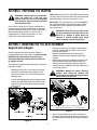
Operator’s Manual
30-inch Hydraulic Tiller Attachment
For FastAttach Compatible Garden Tractors
™
Model
OEM-190-825
NOTE: OEM-190-824 Sleeve Hitch with Electric Lift
(available separately) is required for use of this attachment.
MTD PRODUCTS INC. P.O. BOX 368022 CLEVELAND, OHIO 44136-9722
PRINTED IN U.S.A.
FORM NO. 770-10363B
(11/00)
TABLE OF CONTENTS
Content
Page
Important Safe Operation Practices................................................................... 3
Contents of Carton............................................................................................. 7
Assembling The Tiller ........................................................................................ 8
Know The Tiller .................................................................................................. 13
Operating The Tiller ........................................................................................... 14
Maintenance ...................................................................................................... 16
Parts List............................................................................................................ 19
FINDING MODEL NUMBER
This Operator’s Manual is an important part of your new tiller attachment. It will help you assemble, prepare
and maintain the unit for best performance. Please read and understand what it says.
Before you start assembling your new equipment, please locate the model plate on the
front, left portion of the tiller frame and copy the information from it in the space provided
below. The information on the model plate is very important if you need help from our
Customer Support Department or an authorized dealer.
(Model Number)
(Serial Number)
Copy the model number here:
Copy the serial number here:
MTD PRODUCTS INC
CLEVELAND, OHIO 44136
CALLING CUSTOMER SUPPORT
If you have difficulty assembling this product or have any questions regarding the controls, operation or
maintenance of this unit, please call the Customer Support Department.
Call 1- (330) 220-4MTD (4683) or 1- (800)-800-7310 to reach a Customer Support
representative. Please have your unit’s model number and serial number ready when you
call. See previous section to locate this information. You will be asked to enter the serial
number in order to process your call.
2
SECTION 1: IMPORTANT SAFE OPERATION PRACTICES
WARNING: This symbol points out important safety instructions which, if not followed, could endanger
the personal safety and/or property of yourself and others. Read and follow all instructions in this
manual before attempting to operate this machine. Failure to comply with these instructions may result
in personal injury. When you see this symbol—heed its warning.
DANGER: This machine was built to be operated according to the rules for safe operation in this
manual. As with any type of power equipment, carelessness or error on the part of the operator can
result in serious injury. This machine is capable of amputating hands and feet and throwing objects.
Failure to observe the following safety instructions could result in serious injury or death.
General Operation
•
•
•
•
•
Read this operator’s manual carefully in its entirety
before attempting to assemble this machine. Read,
understand, and follow all instructions on the
machine and in the manual(s) before operation. Be
completely familiar with the controls and the proper
use of this machine before operating it. Keep this
manual in a safe place for future and regular
reference and for ordering replacement parts.
•
•
•
•
This machine is a precision piece of power
equipment, not a plaything. Therefore, exercise
extreme caution at all times. Your unit has been
designed to perform one job: to till soil. Do not use it
for any other purpose.
•
•
•
Never allow children under 14 years old to operate
this machine. Children 14 years old and over should
read and understand the operation instructions and
safety rules in this manual and should be trained
and supervised by a parent. Only responsible
individuals who are familiar with these rules of safe
operation should be allowed to use your machine.
•
•
Thoroughly inspect the area where the equipment is
to be used. Remove all stones, sticks, wire, bones,
toys and other foreign objects which could be
picked up and thrown by the tiller tines in any
direction which could cause serious personal injury
to the operator or any others allowed in the area.
Plan your tilling pattern to avoid discharge of
material toward roads, sidewalks, bystanders and
the like. To help avoid tine contact or a thrown
object injury, keep children, bystanders and helpers
at least 75 feet from the tiller attachment while it is in
operation. Stop tiller if anyone enters the area.
•
Always wear safety glasses or safety goggles
during operation or while performing an adjustment
or repair to protect eyes from foreign objects that
may be thrown from the machine in any direction.
•
Wear sturdy, rough-soled work shoes and closefitting slacks and shirts. Shirts and pants that cover
the arms and legs and steel-toed shoes are
recommended. Loose fitting clothes and jewelry
can be caught in movable parts. Never operate a
unit in bare feet, sandals, slippery or light weight
(e.g. canvas) shoes.
•
•
•
•
•
3
Do not put hands or feet near or under rotating
parts. Keep clear of the tiller tines at all times as the
rotating tines can cause injury.
Never operate the tiller without the rear deflector in
its proper place.
Disengage the PTO and raise the tiller attachment
when crossing gravel drives, walks, or roads.
Watch for traffic when operating near or crossing
roadways. This machine is not intended for use on
any public roadway.
Do not operate while under the influence of alcohol
or drugs.
Use tiller attachment in daylight or in good artificial
light only.
NEVER carry passengers.
Slow down before turning. Operate the machine
smoothly. Avoid erratic operation and excessive
speed.
Use a slow ground speed when tilling soil for the
first time. Fast speeds may cause you to lose
control and may also damage the machine.
Disengage the PTO and raise the tiller attachment
before shifting into reverse and backing up. Always
look down and behind before and while backing up
to avoid a back-over accident.
Disengage the PTO and raise the tiller attachment
before making sharp turns. Leaving the tiller
lowered and engaged may adversely affect the
steering and control of the tractor.
Use extra caution when making turns, especially in
tight areas or around obstacles. The tiller
attachment extends beyond the back of the tractor
and could strike an adjacent object (e.g. tree, fence,
bystander etc.) which could damage the machine or
cause personal injury.
Check overhead clearances carefully before driving
under power lines, wires, bridges, low hanging tree
branches, before entering or exiting buildings, or
any other situation where the operator may be
struck or pulled from the unit, which could result in
serious personal injury.
Disengage the PTO and raise the tiller attachment
when not in use.
Never leave a running machine unattended. Always
disengage PTO, place transmission in neutral, set
parking brake, turn engine off and remove key
before dismounting.
•
•
•
•
Disengage the PTO, stop the engine and wait until
the tiller comes to a complete stop before making
any repairs, adjustments, or removing any rocks or
debris.
Use extra caution when loading or unloading the
machine into a trailer or truck. A tractor with a tiller
attachment should not be driven up or down a ramp
onto a trailer or truck under power, the unit could tip
over causing serious personal injury. The unit must
be pushed manually to load or unload properly.
Follow all manufacturer’s recommendations for use
of counterweights to improve machine stability.
If situations occur which are not covered in this
manual, use care and good judgment. Contact your
dealer for assistance. Telephone 1-800-800-7310
for the name of your nearest authorized service
dealer.
•
•
•
•
Children
Tragic accidents can occur if the operator is not alert to
the presence of children. Children are often attracted to
the machine and the tilling activity. They do not
understand the dangers. Never assume that children
will remain where you last saw them.
Slope Operation
•
Slopes are a major factor related to loss of control and
tip-over accidents which can result in severe injury or
death. Operation on slopes requires extra caution. If
you cannot back up the slope or if you feel uneasy on it,
do not till it. For your safety, use the slope gauge
included as part of this manual to measure slopes
before operating this unit on a sloped or hilly area. If the
slope is greater than 10 degrees as shown on the slope
gauge, do not operate this unit on that area or serious
injury could result.
•
•
•
Do:
•
•
•
•
•
•
•
•
Till up and down slopes, not across. Exercise
extreme caution when changing direction on slopes.
Watch for holes, ruts, bumps, and hidden objects
(e.g. rocks etc.) which can be under the soil.
Uneven terrain could overturn the machine which
may cause personal injury.
Use slow speed. Choose a low enough speed
setting so that you will not have to stop or shift while
on the slope. Always keep the machine in gear
when going down slopes to take advantage of the
engine braking action.
Keep all movements on slopes slow and gradual.
Do not make sudden changes in speed or direction.
Rapid engagement or braking could cause the front
of the machine to lift and rapidly flip over backwards
which could cause serious personal injury.
Avoid starting and stopping on a slope. If tires lose
traction, Disengage the PTO and proceed slowly
straight down the slope.
Use extra care with the tiller attachment as it can
change the stability of the machine.
Follow all manufacturer’s recommendations for
wheel weights or counterweights to improve the
stability of the machine.
•
•
Keep children out of the tilling area and under the
watchful care of a responsible adult other than the
operator.
Be alert and turn the machine off if a child enters the
area.
Before and while moving backwards, look behind
and down for small children.
Use extreme care when approaching blind corners,
doorways, shrubs, trees, or other objects that may
obscure your vision of a child who may run into the
machine.
NEVER carry children, even with the attachment
disengaged. They may fall off and be seriously
injured or interfere with safe machine operation.
Keep children away from hot or running engines.
They can suffer burns from a hot muffler.
Remove key when machine is unattended to
prevent unauthorized operation.
Never allow children under 14 years old to operate a
power mower. Children 14 years old and over should
read and understand the operation instructions and
safety rules in this manual and should be trained and
supervised by a parent.
Service
Safe Handling of Gasoline:
To avoid personal injury or property damage use
extreme care in handling gasoline. Gasoline is
extremely flammable and the vapors are explosive.
Serious personal injury can occur when gasoline is
spilled on yourself or your clothes which can ignite.
Wash your skin and change clothes immediately.
•
•
Do Not:
•
Do not till near drop-offs, ditches or embankments.
The machine could suddenly overturn if a wheel or
the attachment is over the edge, or if the edge
caves in.
Do not operate machine on wet grass. Reduced
traction could cause sliding and loss of control of the
machine.
Do not try to stabilize the machine by putting your
foot on the ground.
Do not till slopes greater than 10 degrees as shown
on the slope gauge.
Do not turn on slopes unless necessary; then, turn
slowly and gradually downhill, if possible.
•
4
Use only an approved gasoline container.
Extinguish all cigarettes, cigars, pipes and other
sources of ignition.
Never fuel machine indoors because flammable
vapors will accumulate in the area.
•
•
•
•
•
•
•
Never remove gas cap or add fuel while the engine
is hot or running. Allow engine to cool at least two
minutes before refueling.
Never over fill fuel tank. Fill tank to no more than ½
inch below bottom of filler neck to provide space for
fuel expansion.
Replace gasoline cap and tighten securely.
If gasoline is spilled, wipe it off the engine and
equipment. Move unit to another area. Wait 5
minutes before starting the engine.
Never store the machine or fuel container inside
where there is an open flame, spark or pilot light as
on a water heater, space heater, furnace, clothes
dryer or other gas appliances.
To reduce fire hazard, keep machine free of grass,
leaves, or other debris build-up. Clean up oil or fuel
spillage and remove any fuel soaked debris.
Allow machine to cool at least 5 minutes before
storing.
•
•
•
•
•
General Service:
•
•
•
•
•
Never run an engine indoors or in a poorly
ventilated area. Engine exhaust contains carbon
monoxide, an odorless and deadly gas.
Before cleaning, repairing, or inspecting, make
certain the tines and all moving parts have stopped.
Disconnect the spark plug wire and ground against
the engine to prevent unintended starting.
Never attempt to make adjustments or repairs to the
machine while the engine is running.
Never check for leaks in the hydraulic lines with
your hands. Hot, high pressure fluid can escape
through a pin hole leak and cause serious injury by
puncturing the skin and causing blood poisoning.
Observe proper disposal laws and regulations.
Improper disposal of fluids and materials can harm
the environment.
•
•
•
•
•
Muffler, engine and belt guards become hot during
normal operation and can cause a burn. Hydraulic
hoses, fittings and fluid also become hot during
normal operation. Allow the machine, tiller
attachment, and its related hardware time to cool
before cleaning, repairing, or inspecting.
Check the tine mounting bolts at frequent intervals
for proper tightness. Also, visually inspect tines for
damage (e.g., bent, cracked, worn etc.) Replace
tines with the original equipment manufacture’s
(O.E.M.) tines only, listed in this manual. “Use of
parts which do not meet the original equipment
specifications may lead to improper performance
and compromise safety!”
Tiller tines are sharp and can cause serious injury.
Wrap the tines or wear gloves, and use extra
caution when servicing them.
Keep all nuts, bolts, and screws tight to be sure the
equipment is in safe working condition.
Never tamper with safety devices. Check their
proper operation regularly. Use all guards as
instructed in this manual.
After striking a foreign object, stop the engine,
disconnect the spark plug wire and ground against
the engine. Thoroughly inspect the machine for any
damage. Repair the damage before starting and
operating.
Check brake operation frequently as it is subjected
to wear during normal operation. Adjust and service
as required.
If the tractor or tiller attachment should begin to
vibrate abnormally, stop the engine and check over
the equipment immediately for the cause. Abnormal
vibration is a warning of a problem.
Do not change the engine governor setting or
overspeed the engine.
Maintain or replace safety and instruction labels, as
necessary.
Your Responsibility
Restrict the use of this power machine to persons who read, understand and follow the warnings and
instructions in this manual and on the machine. The safety label on the equipment is reproduced
below. Take a moment to study the label before operating the unit. Always maintain safety while
operating or servicing the equipment.
5
SECTION 2: SLOPE GAUGE
10°
FOLD
ON
A POWER POLE
A CORNER OF A BUILDING
OR A FENCE POST
PE
SIGHT AND HOLD THIS LEVEL WITH A VERTICAL TREE
DOTT
E
D LIN
E
,
R
E
PRES
ENT
I
N
G
A
10° SL
O
WARNING
Do not use the tiller attachment and tractor on inclines with a slope in excess of 10 degrees (a rise of approximately 2 feet every
10 feet). A riding mower could overturn and cause serious injury.
Operate RIDING mowers up and down slopes, never across the face of slopes.
SECTION 3: TO THE OWNER
Model OEM-190-825 hydraulic tiller attachment is designed for use on FastAttach compatible Garden Tractors
only. It will NOT fit nor operate properly or safely on ANY other tractor. It will NOT fit nor operate properly or
safely on FastAttach compatible Lawn Tractors. The use of OEM-190-825 hydraulic tiller attachment on
FastAttach compatible Lawn Tractors will void the tractor’s warranty as to resulting damages.
™
™
™
The use of Model OEM-190-824 Electric Sleeve Hitch (NOT included with OEM-190-825 hydraulic tiller attachment)
is required for the proper operation of this tiller attachment. The use of the front weights (included with OEM-190825 hydraulic tiller attachment) is also required for the safe and proper operation of this tiller attachment.
The instructions in this manual are divided into sections. Carefully read all sections and study the illustrations to
ensure proper installation and usage of this attachment. Read and observe all WARNING statements. They are
included to provide for the protection of the equipment installer and operator, and to ensure the prolonged service
life of the equipment.
References to LEFT and RIGHT indicate the left and right sides of the tractor and tiller attachment when facing
forward in the operator’s position. Reference to the FRONT indicates the grille end of the tractor and reference to
the REAR indicates the drawbar end where the tiller attaches.
SECTION 4: CONTENTS OF CARTON
The carton contents of OEM-190-825 hydraulic tiller attachment are listed below and shown in Figure 1. Remove
all loose parts from the carton before discarding it. Refer to Figure 1 throughout the following sections of the
manual to identify the parts, noting that these parts will be referred to again.
•
•
•
One Tiller Assembly
One Undercarriage Assembly w/ Hydraulic Pump
One Front Weight Bracket w/ Three 45 lb. Weights
•
•
•
Two Hydraulic Hoses
One V-belt (754-0490) for Electric PTO Tractors
One V-belt (754-0341) for Manual PTO Tractors
V-belt (754-0341)
For Manual PTO Tractors
Tiller Assembly
V-belt (754-0490)
For Electric PTO Tractors
Front Weight Bracket
with Three 45 lb. Weights
Undercarriage Assembly
with Hydraulic Pump
Hydraulic Hoses
NOTE: Two upper drive belts are included with the tiller attachment. The belt (754-0490) packaged with the undercarriage
assembly in the separate box is for use on tractor’s equipped with an electric PTO. The other upper drive belt
(754-0341) is for use on tractor’s with a manual PTO. Belt part numbers are stamped on the outer edge of the belts.
Figure 1
7
SECTION 5: ASSEMBLING THE TILLER
Attaching the Hydraulic Hoses
Small Diameter
Hose Fitting
Two hydraulic hoses are packaged separately in the
carton. Both hoses have female connectors on either
end and will attach to male connectors on both the
hydraulic pump assembly (found on the underside of
the undercarriage assembly) and the tiller assembly
itself.
A
A
Large Diameter
Hose Fitting
To connect the hydraulic hoses to the hydraulic pump
assembly, proceed as follows:
•
Locate the two male hydraulic fittings on the rear of
the hydraulic pump found on the underside of the
undercarriage assembly. Note that one fitting has a
noticeably larger diameter than the other.
•
Hand tighten the end of the smaller diameter hose
onto the smaller male fitting of the hydraulic pump.
Figure 2
IMPORTANT: Make certain not to cross thread the
connectors when attaching the hoses to the hydraulic
pump.
•
Repeat the previous step for the large diameter
hydraulic hose.
•
Use two wrenches (one wrench to prevent the hose
from spinning while tightening, and the other to
tighten the connectors together) to securely fasten
the hoses to the hydraulic pump.
IMPORTANT: Make certain that the hose connectors
are tightly secured to the fittings on both the hydraulic
pump AND the tiller assembly before proceeding on to
Filling the Hydraulic Reservoir.
Filling the Hydraulic Reservoir
The tiller attachment operates using hydraulic fluid. Add
the fluid ONLY after all the hydraulic hoses are
connected. The following list includes fluids that are
approved for use in this tiller:
The tiller comes shipped as an assembly. The tiller
does not, however, get shipped with the hydraulic fluid
that is required to drive the tiller. Before adding any
fluid, the two hydraulic hoses that are attached to the
hydraulic pump assembly need to be secured to the
tiller.
• Mobile 424
• Texaco TDH
• Shell Donax
• Farmland TF
• Citgo TF
• Sun Tractor Fluid
• Amoco 1000
• Shell TTF
To properly fill the hydraulic reservoir on the tiller
assembly, proceed as follows:
To connect the hydraulic hoses to the tiller assembly,
proceed as follows:
•
•
Locate the two male hydraulic fittings on the front of
the tiller assembly. Note that one fitting has a
noticeably larger diameter than the other. See
Figure 2.
•
•
Attach the hoses to the tiller in the same fashion as
they were attached to the hydraulic pump in
previous steps.
•
Remove the hydraulic tank dipstick/cap from the
top of the tiller assembly.
Carefully pour 4-½ gallons of hydraulic fluid into the
opening.
Replace the dipstick.
To connect the hydraulic hose leading from the
hydraulic motor to the hydraulic valve on the right side
of the tiller assembly, proceed as follows:
IMPORTANT: Be certain to recheck the hydraulic fluid
level after the tiller has been mounted on the tractor and
the hydraulic pump has been engaged.
•
NOTE: Refer to the MAINTENANCE section of this
manual for detailed instructions regarding checking the
fluid level & changing the hydraulic fluid and filter.
Thread the hose end labeled “A” in Figure 2 to the
90° adapter labeled “A” in Figure 2. Tighten
securely.
8
SECTION 6: PREPARING THE TRACTOR
NOTE: References to LEFT and RIGHT indicate the left
and right sides of the tractor and/or the tiller attachment
from the operator’s position in the tractor’s seat.
WARNING: Before beginning installation,
place the tractor on a firm and level
surface. Place the PTO in the disengaged
(OFF) position, stop the tractor engine and
set the parking brake.
IMPORTANT: The use of this tiller attachment requires
the use of the weight bracket and three 45 lb. weights
(included with this tiller attachment) mounted on the
front of the tractor.
Your tractor’s cutting deck, PTO belt and front deck
stabilizer bracket must be removed prior to mounting
the tiller attachment. Refer to your tractor’s Operator’s
Manual for detailed instructions. If your tractor is
equipped with any front-end accessory (i.e. front
bumper kit), it must also be removed.
WARNING: Never operate your tractor with
the tiller attachment mounted without the
three 45 lb. weights in place. Doing so
presents a tip-over hazard which could
result in serious injury to the operator.
SECTION 7: MOUNTING THE TILLER ATTACHMENT
Weight Bracket & Weights
•
A front weight bracket with three 45 lb. weights is
packaged separately in the carton. The tractor should
NEVER be operated with the tiller attachment
mounted without the weight bracket and three 45
lb. weights in place.
•
•
To connect the weight bracket to the tractor’s front-end,
proceed as follows:
•
Remove the clevis pins, flat washers and hairpin
clips found on both sides of the weight bracket.
Save this hardware, as it will be reinserted in the
following steps.
•
Position the slotted portions of the weight bracket
over the shoulder bolts found on the left and right
sides of the tractor’s front pivot support brackets.
See Figure 3.
•
Reinsert the clevis pins through the aligning holes
in both the weight bracket and the tractor’s front
pivot support brackets.
Secure the weight bracket by reattaching the
washers and hairpin clips removed earlier. See
Figure 3.
Remove the hairpin clip and washer from one end
of the hold down rod on the weight bracket and
slide the rod out the opposite side. See Figure 3.
Carefully place the weights onto the bracket one at
a time. See Figure 4.
WARNING: Weights are heavy. Exercise
caution when lifting the weights and
placing them onto the front weight bracket.
Do NOT overexert yourself.
Hairpin
Clip
Washer
NOTE: Only one weight is shown for clarity. ALL three
weights must be mounted prior to operating the tiller.
Shoulder Bolt
Figure 4
Slots
•
Hold Down Rod
Clevis Pin
Figure 3
9
After all three weights are mounted, reinsert the
hold down rod into the weight bracket and secure it
by reattaching the hairpin clip and washer removed
earlier.
Tiller
Tiller Assembly
Tiller Stand
Large Diameter
Hydraulic Hose
Hairpin Clips
IMPORTANT: If your tractor
is equipped with an electric
PTO, remove this keeper
pin prior to mounting the
undercarriage assembly.
Small Diameter
Hydraulic Hose
Undercarriage Assembly
with Hydraulic Pump
Figure 5
Undercarriage Assembly
•
•
•
Hairpin Clip
With the tiller stand lowered to support the weight of
the tiller assembly, position the undercarriage
assembly and tiller assembly (with the hoses
attached) as shown in Figure 5 on a cleared, flat
surface.
Remove the two hairpin clips (and the clevis pins
they’re securing) from the rear of the undercarriage
assembly. See Figure 6. Also remove the four
hairpin clips and flat washers from the four weld
pins found on the top side of the undercarriage
assembly. Save this hardware, as it will be
reinserted in the following steps.
If your tractor is equipped with an electric PTO,
remove the front, right keeper pin from the
undercarriage assembly. See Figure 5.
Clevis Pin
Undercarriage Assembly
with Hydraulic Pump
•
•
•
Weld Pins
NOTE: Only the Right Hand lift arm is shown for clarity.
Figure 6
•
Carefully position (by pushing, NOT driving) the
tractor over the undercarriage assembly.
IMPORTANT: Be very careful NOT to roll one of the
tractor’s rear tires over the hydraulic hoses.
•
Lift Arm
(Attached to Tractor)
Weld Pin
IMPORTANT: If the sleeve hitch (OEM-190-824) has not
been mounted to the tractor at this point of the
assembly, do so before proceeding on to the next step.
•
Weld Pin
•
Set the tractor’s parking brake to keep the tractor
from rolling.
Move the tractor’s lift lever into the lowest notch on
the right fender allowing the lift arms located
beneath the tractor to drop.
Reinsert the clevis pin removed earlier from the
right side of the undercarriage assembly into
aligning holes in both the undercarriage assembly
and the tractor’s right lift arm. See Figure 6.
Repeat the previous step on the left side of the
undercarriage assembly.
Carefully move the tractor’s lift lever into the
highest notch on the right fender allowing the lift
arms, with the rear portion of the undercarriage
assembly fastened to it to rise.
Pivot the front portion of the undercarriage
assembly upward so that the weld pins (Refer to
Figure 6) located on the top side of the
undercarriage align with the holes found in both the
left frame rail and the right frame rail of the tractor.
IMPORTANT: Make certain that the belt is routed to the
OUTSIDE of the front left weld pin as illustrated in
Figure 6 before proceeding on to the next step.
•
10
Insert the weld pins into the frame rail holes and
secure them by reattaching the washers and
hairpin clips removed earlier.
•
Repeat the previous step on the rear of the
undercarriage assembly.
Tiller Assembly
Note how the electric sleeve hitch cylinder shaft is
attached to the sleeve hitch U-bracket (refer to Figure 7
& Figure 8) before proceeding on to the first step below.
Upon completing the following steps, the tiller assembly
will be attached to the sleeve hitch cylinder shaft in the
exact same manner.
Hitch Rod
Remove the sleeve hitch U-bracket from the sleeve
hitch assembly as follows:
•
Hairpin Clip
Remove the two hairpin clips securing the hitch rod
to the sleeve hitch U-bracket. Do NOT, however,
remove the hitch rod yet. This will be done in
following steps. See Figure 7.
•
Remove the two washers and two hairpin clips (Not
visible in Figure 7, Refer to Figure 8) securing the
lower cylinder support rod to the sleeve hitch
assembly.
•
Remove the lower cylinder support rod. This will
allow the sleeve hitch U-bracket to pivot downward.
Sleeve Hitch
U-bracket
NOTE: Although the tiller assembly (with hydraulic hoses attached)
would be resting behind the tractor at this point in the
assembly, neither are illustrated for clarity.
Figure 7
IMPORTANT: Be careful not to lose the two spacers
(Refer to Figure 8) found on the lower cylinder support
rod.
•
Hitch Rod
Remove the hitch rod, freeing the sleeve hitch Ubracket entirely.
Hairpin Clip
Spacers/
Lower Cylinder Support Rod
NOTE: Store the sleeve hitch U-bracket in a safe
place. It is NOT needed to mount and operate this tiller
attachment, but is required for use with other tractor
rear-end attachments.
Hairpin Clip
Figure 8
Hitch Latches
•
•
Reinsert the hitch rod back into the holes in the
sleeve hitch bracket and secure it with the hairpin
clips removed earlier. See Figure 8. Do NOT
reinsert the lower cylinder support rod yet. This will
be done in later steps.
Slot
Remove the two clevis pins from the hitch latches
found on both sides of the tiller assembly by first
removing the two hairpin clips which secure them in
place. See Figure 9.
Hairpin Clip
IMPORTANT: If it’s not already raised, use the toggle
Clevis Pins
switch from OEM-190-824 to place the electric lift
cylinder shaft into the fully raised position before
proceeding on to the next step.
Figure 9
11
IMPORTANT:Before proceeding to the next step, make
certain that both the large diameter hose and the small
diameter hose are routed to the INSIDE of both hitch
latches as illustrated in Figure 10 & Figure 11. Failure to
properly route the hoses may cause the tractor tire
coming in constant contact with a hydraulic hose,
resulting in premature wear.
•
•
•
Insert the lower cylinder support rod through the
two spacers removed earlier, the sleeve hitch
cylinder shaft and both slots found in the tiller
assembly as illustrated in Figure 12.
NOTE: The sleeve hitch cylinder shaft will have to be
lowered using the toggle switch on the tractor’s dash to
properly secure the lower cylinder support rod to the
tiller assembly.
Position the slotted portions on the front of the tiller
assembly (found to the INSIDE of the hitch latches,
refer to Figure 9) onto the hitch rod of the sleeve
hitch. The hitch latches will then fall into place over
the hitch rod.
Reinsert the clevis pins into the aligning holes in
both the tiller assembly and the hitch latches and
secure them with the hairpin clips removed earlier.
Refer to Figure 10.
•
Secure the lower cylinder support rod in place with
the washers and hairpin clips removed earlier. See
Figure 12.
Cylinder
Shaft
Spacers
Hairpin
Clip
Washer
Slots
Washer
Hairpin Clip
Figure 12
Figure 10
•
Be certain that the hoses are routed as illustrated in
Figure 11 before proceeding on to the next step.
Routing The Tiller Drive Belt
IMPORTANT: Make certain that the correct belt is in
place on the undercarriage assembly prior to
attempting to route the belt on the tractor’s PTO. Refer
to the NOTE in Figure 1 on page 7.
Large Diameter Hose
Route the tiller drive belt in the same manner that the
tractor’s cutting deck PTO belt was routed. Refer to the
MAINTENANCE section of your tractor’s Operator’s
Manual.
Hitch
Rod
IMPORTANT: Make certain that the belt is routed to the
INSIDE of all four keeper pins surrounding the large
pulley on the top side of the undercarriage assembly
and the INSIDE of the idler pulley belt guard found on
the front left portion of the undercarriage assembly
before operating the tiller.
Small
Diameter Hose
NOTE: Top View Shown
Figure 11
12
SECTION 8: KNOW THE TILLER
Dipstick/Reservoir Cap
Hydraulic Reservoir
Tine Direction Lever
Hydraulic Filter
Drain Plug
Hydraulic Control Valve
Tiller Stand
(Lowered Position)
Hydraulic Motor
Tiller Tines
Figure 13
Tine Direction Lever
The tine direction lever is located on the top of the tiller
attachment on the right side of the unit. See Figure 13.
This lever is used to control which direction the tines
turn.
IMPORTANT: Always place the tractor’s PTO in the
disengaged (OFF) position before changing the
direction of the tines. Failure to do so WILL result in
serious damage to the tiller’s hydraulic motor.
Tiller Tines
The tiller’s tines are located under the frame of the tiller.
The tines cultivate the soil when placed in contact with
the ground with the tractor in motion.
Figure 14
The tines are replaceable and wear should be
expected. The rate of wear will vary with application.
Hydraulic Pump
Located on the underside of the undercarriage
assembly, the hydraulic pump is driven by a belt
engaged and disengaged with the tractor’s PTO.The
hydraulic pump moves fluid through hydraulic hoses to
and from the hydraulic motor found on the tiller.
WARNING: Tiller tines are sharp and can
cause serious injury. Always wear heavy
gloves when servicing the tines.
Hydraulic Filter
The hydraulic system on the tiller attachment has a filter
that is located directly to the left of the hydraulic control
valve. The filter (Part No. 723-0405) keeps the
hydraulic fluid free from impurities and should be
changed according to manufacturer’s data as listed in
the MAINTENANCE section of this manual.
NOTE: The PTO on the tractor will not function while
the tractor is traveling in reverse. Use the tiller only
while traveling forward. See SAFETY INTERLOCK
SWITCHES in the OPERATION section of your
tractor’s Operator’s Manual for more detailed
information.
13
Hydraulic Reservoir
•
The hydraulic reservoir is a part of the tiller frame and
can be filled by removing the dipstick/reservoir cap
located directly on top of the tiller in the center. The
dipstick/reservoir cap is vented to allow for expansion
of the hydraulic fluid as it heats up during normal use.
Pull the hairpin clip which secures the clevis pin to
the tiller stand. See Figure 15.
Hairpin Clip
IMPORTANT: Always maintain the correct level of fluid in
the reservoir. Failure to do so could result in serious
damage to the hydraulic motor.
Clevis Pin
WARNING: Hydraulic hoses, fittings, and
fluid become hot during normal usage.
Allow the machine to cool down before
checking fluid level or performing any
maintenance.
Tiller Stand
(In Lowered Position)
Operating Position Hole
Tiller Stand
Figure 15
The tiller attachment is equipped with a stand located
on the front, left portion of the tiller which allows the
assembly to balance on its own when it is not attached
to the tractor. To apply the tiller stand, proceed as
follows:
•
•
Remove the clevis pin before positioning the tiller
stand in either the operating position or the lowered
position.
Reinsert the clevis pin and secure with the hairpin
clip removed earlier.
SECTION 9: OPERATING THE TILLER
IMPORTANT: The use of this tiller attachment requires
the use of the weight bracket and three 45 lb. weights
(included with this tiller attachment).
N is the neutral position. When the lever is in this
position, the tiller tines are not in motion. Place the
tine direction lever in neutral whenever transporting
the unit.
R is the reverse (counter-rotating) tilling position.
Pushing the tine direction lever toward the rear of
the tiller, or away from the operator, engages the
tines into a counter-rotating tilling motion (Refer to
Figure 13). Reverse direction tilling is used for
breaking ground or tilling hard soil.
The tiller attachment’s tines are engaged in the same
manner as the blades on a cutting deck attachment, by
placing the tractor’s PTO in the engaged (ON) position.
Always place the tine direction lever in either F or R
BEFORE engaging the tractor’s PTO.
WARNING: Never operate your tractor with
the tiller attachment mounted without the
three 45 lb. weights in place.
Fluid Level
IMPORTANT: Check the tiller’s hydraulic fluid level as
instructed in the ASSEMBLY section of this manual
before using the unit. Read instructions carefully.
WARNING: Never check the hydraulic oil
level immediately after using the tiller.
Hydraulic oil reaches high temperatures
during normal usage and may build
pressure in the system. Allow the tiller to
cool before checking the fluid level.
IMPORTANT: Always turn the tractor’s PTO into the
disengaged (OFF) position before changing tine
direction. Do not move the tine direction lever with the
PTO engaged. Doing so will result in serious damage to
the hydraulic motor.
Engaging the Tines
WARNING: Before engaging the tiller tines,
place the tractor’s PTO in the disengaged
(OFF) position, and set the parking brake.
The tiller attachment’s tine direction lever can be placed
in one of the three following positions:
F is the forward tilling position. Pulling the tine
direction lever toward the front of the tractor
engages the tines into a forward tilling motion
(Refer to Figure 13). Forward tilling should be used
for cultivating or tilling soft soil.
Lower the tiller attachment into the ground only after
carrying out the following steps in the order listed:
•
Set the height of both tiller skids for your tilling
application. Refer to Tilling Depth on the following
page for detailed instructions.
14
•
•
•
•
•
Tilling Depth
Apply the tractor’s parking brake to stabilize your
position.
Make certain the tiller stand is in the fully raised
(Operating) position. See Figure 13 and Figure 15.
Place the tractor’s throttle in the FAST (Rabbit)
position)
Place the tiller attachment’s tine direction lever in
either the Forward or Reverse position.
Place the tractor’s PTO in the engaged (ON)
position.
The tilling depth is established by a combination of two
different methods: Adjusting the height of the tiller
attachment’s skids and using the toggle switch installed
as part of OEM-190-824 to raise and lower the tiller
attachment.
Tiller Skids
The depth of tilling is determined in part by the position
at which the skids are set. To adjust the tiller skids,
proceed as follows:
NOTE: Be alert! It is normal for the operator to
experience tractor and tiller vibration as the tiller
penetrates the ground initially.
•
Rotate the adjustment crank found on the right side
of the tiller attachment six to eight turns counterclockwise. See Figure 16.
Tilling Ground Speed
Tilling ground speed is the speed at which the tractor is
traveling with the tiller engaged and lowered into the
ground. Correct ground speed is determined by the soil
conditions and the depth of cut.
Adjuster Bracket
IMPORTANT: Regardless of soil conditions, the tiller
Notches
attachment should ALWAYS be operated with the
tractor’s throttle in the FAST (Rabbit) position.
IMPORTANT: NEVER attempt to operate the tiller
attachment while traveling in the Reverse direction. The
PTO on the tractor will not function while the tractor is
traveling in reverse. Use the tiller only while traveling
forward.
Skid
Adjustment Crank
Hard Soil
Tines
Figure 16
Maintain a ground speed of approximately 30% of the
top speed of the tractor. If the engine is continually
“bogging down” or the tractor and/or tiller is vibrating or
shaking, the ground speed should be slowed.
•
•
Soft or Previously Tilled Soil
Maintain a ground speed of approximately 50% of the
top speed of the tractor. If a noticeable vibration or
shaking of the tiller attachment should occur, the
ground speed should be slowed.
Position the skid up or down before tightening the
adjuster crank into one of the four notches found on
the skid adjuster bracket. See Figure 16.
Repeat the previous steps on the left side of the
tiller attachment.
Wet Soil
NOTE: Tightening the adjuster crank into a higher
notch will decrease tilling depth. Tightening the
adjuster crank into a lower notch will increase tilling
depth. Always position the cranks on both sides of the
tiller attachment into the same notches for level tilling.
Tilling soil that is wet is NOT recommended. Doing so
will usually result in the formation of large clumps of soil
that will dry solid and need to be tilled again.
Depending on the height of the tiller skids, the tines
have an approximate tilling depth ranging between 1”
and 6-½”.
The potential to get the tractor stuck while tilling is
increased substantially while tilling wet soil. If the
tractor’s tires begin to spin as a result of lost traction,
place the tractor’s PTO in the disengaged (OFF)
position, raise the tiller out of the ground, and attempt to
drive out of the area.
WARNING: NEVER set the tiller depth
while the tractor is in motion.
IMPORTANT: ALWAYS bring the tractor to a complete
stop before raising or lowering the tiller attachment.
When tilling hard ground or when tilling an area for the
first time, do not till more than 2” at a time. To increase
the tilling depth, lower the tiller on successive passes
over the area.
NOTE: Under any ground conditions, a slow and
consistent ground speed while tilling will produce the
finest tilled soil.
15
Operating Tips
•
•
Stop the tractor’s forward motion.
Raise the tiller out of the ground using the toggle
switch installed as part of OEM-190-824.
• Place the tine direction lever in position so that the
tines will spin in the opposite direction that they
were spinning when the tilling motion stopped (i.e.
If the tiller was in the forward (F) position when it
stopped, shift into the reverse (R) position).
• Place the tractor’s PTO in the engaged (ON)
position.
The foreign object should be expelled from the tines.
For best results while tilling, always till the area at least
twice. Till the second pass over an area at a right angle
from the first pass (criss-cross pattern).
Turning
The tiller attachment was intended to be used in a
straight line only. Very slight turns while tilling can be
achieved by traveling at a slower ground speed, but
sharp turns during tilling will put excess stress on the
frame of the tiller and tractor and will cause the
equipment to shake and vibrate excessively.
Always raise the tiller attachment out of the ground
before executing a sharp turn.
If the object does not dislodge using this method and
the hydraulic motor begins to make a “whining” sound
again, proceed as follows:
Clearance
•
The left hand side of the tiller attachment lines up
evenly with the left hand tires of the tractor. To get
nearest to an object while tilling, line the object up just
to the left side of the tractor.
•
•
The tiller attachment makes the tractor noticeably
longer. Be careful in turns! Watch the rear end
clearance of the tiller attachment. In a tight turn, the
tiller sticks out and may strike an object that the tractor
itself normally would not come near.
•
•
•
Foreign Object in Tines
If a large rock or foreign object gets caught in the
spinning tines, a squealing sound will occur from the
hydraulic motor area of the tiller attachment and the
tines will stop spinning. If this occurs, proceed as
follows:
•
Immediately place the PTO in the disengaged
(OFF) position.
Drive the tractor to a firm and level surface.
Shift the tine direction lever to neutral (N) and raise
the tiller to its highest position using the toggle
switch installed as part of OEM-190-824.
Stop the tractor engine and set the parking
brake.
Pivot the rear tine shield upward, if necessary, and
locate the object that is binding the tines.
Using a broom handle or heavy stick, dislodge the
object from between the tines and the tiller housing.
IMPORTANT: If it is absolutely necessary to reach into
the tine area with your hand to remove an object, use
caution around the tines which may be sharp.
WARNING: Tiller tines are sharp and can
cause serious injury. Wear heavy gloves
and use extra caution servicing tines.
Immediately place the tractor’s PTO in the
disengaged (OFF) position.
SECTION 10: MAINTENANCE
WARNING: Before performing any
maintenance, place the tractor on a firm
and level surface. Place the PTO in the
disengaged (OFF) position, stop the
tractor engine and set the parking brake.
After washing the underside of the tiller, start the tiller
tines in motion for a couple minutes to help disperse
any standing water that may be near the bearings and
tine shaft areas.
IMPORTANT: Always wipe up any standing water in the
area around the dipstick/reservoir cap with a dry rag to
avoid possible water contamination while checking the
hydraulic fluid.
WARNING: If working on the tiller tines,
raise the tiller to its highest point and
place blocks under the edges of the tiller
frame to stabilize it. Always wear gloves.
IMPORTANT: Always dry the tiller attachment and
electric sleeve hitch attachments well with either an air
hose or towel after cleaning.
Cleaning
It is important to clean the tiller, especially the area
around the tines, after every use with a hose or
pressure washer.
Lubrication
There are several lubrication points on the tiller
attachment. Using a lithium based lubricant such as
white lithium spray (do NOT use WD-40), coat all the
points where the tiller pivots when raising and lowering.
Such points include:
IMPORTANT: Do NOT apply direct water pressure on or
near the electric lift cylinder. Also, avoid direct water
contact with the dipstick/reservoir cap on top of the
hydraulic reservoir.
16
•
•
•
The entire area around both the hitch latches.
The entire area around both the upper support rod
and lower support rod on the electric lift cylinder.
All clevis pins and hairpin clips on both the tiller
attachment and the electric sleeve hitch
attachment.
•
Thread the dipstick/reservoir cap back onto the
hydraulic reservoir before removing it again to
check the level of the fluid level on the dipstick. Add
hydraulic fluid as necessary. See Figure 17.
Lubricating should be done after at least every 10
hours of operation on the tiller to prevent corrosion and
maintain free movement.
LE V
Hydraulic Filter and Fluid
WARNING: Hydraulic hoses, fittings, and
fluid become hot during normal usage.
Allow the machine and its related
hardware to cool down before checking
fluid level or performing maintenance.
EL C
OL D
F IL L
Fluid Level Should Reach, But NOT Exceed, Hole
Figure 17
Changing the Hydraulic Filter
Changing the Hydraulic Fluid
The hydraulic filter should be changed after every 50
hours of operation on the tiller. To change the filter,
proceed as follows:
The hydraulic fluid in the tiller attachment should be
changed after every 100 hours of operation. To change
the fluid, proceed as follows:
•
•
•
Place a pan (with a height less than 1-½”) under the
oil filter to collect any residual oil from the filter.
Using an oil filter wrench, turn the filter counterclockwise to unthread the filter from the filter head.
The residual oil will drain into the pan.
After first moistening the O-ring on the new filter
with hydraulic oil, thread the new filter (Part No.
723-0405) onto the filter head.
•
•
•
Remove the tiller attachment (but NOT the electric
sleeve hitch attachment) from the tractor.
With the tiller stand fully raised in the operating
position, carefully pivot the tiller forward allowing it
to rest on the tines and lift latches.
Locate the drain plug on the front left side of the
tiller. See Figure 18.
Dipstick/Reservoir Cap
IMPORTANT: Once the filter O-ring makes contact with
Tiller Stand
(Raised Position)
the filter head, tighten it an additional ¼ turn.
After installing the new filter, operate the tiller (in the
raised position, NOT in the ground) for about one
minute in order to circulate the oil.
IMPORTANT: After changing the hydraulic filter, always
check the hydraulic level prior to operating the tiller
attachment for an extended period.
Checking the Hydraulic Fluid Level
Drain Plug
It is very important that the proper amount of hydraulic
fluid is in the hydraulic reservoir to operate the tiller
attachment. Failure to maintain the proper fluid level
WILL result in serious damage to the hydraulic pump
and motor.
Hitch Latches
Check the hydraulic fluid level before every use (when
fluid is cold) as follows:
•
•
•
Figure 18
Turn off the tiller attachment as instructed in earlier
sections of this manual, stop the tractor engine and
set the parking brake.
Lower the tiller using the toggle switch installed as
part of OEM-190-824 until the top flat surface of the
tiller attachment is parallel with the ground.
Remove the dipstick/reservoir cap and wipe it clean
of any hydraulic fluid present.
•
•
•
17
Place an oil collection pan with a capacity of at least
five gallons under the drain plug.
Using a 5/8” wrench, remove the drain plug and
allow the fluid to drain completely.
Examine the drain plug closely before reinstalling it.
If its gasket shows any signs of cracks or tearing,
replace it before reinstalling the drain plug.
•
•
Reinstall the drain plug and tighten securely.
Place the tiller attachment back to a level position
and lower the tiller stand to support it.
• Remove the dipstick/reservoir cap from the hydraulic
fluid reservoir and carefully pour in four gallons of
hydraulic fluid.
The following list includes fluids that are approved for
use in this tiller:
•
•
•
•
•
•
•
•
Front of Tiller
Hex Nuts
Mobile 424
Texaco TDH
Shell Donax
Farmland TF
Citgo TF
Sun Tractor Fluid
Amoco 1000
Shell TTF
Lock
Washers
m
NOTE: The hydraulic reservoir has a capacity of 4-½
gallons. In most cases, however, it is NOT possible to
drain ALL of the fluid when changing it and residual oil
will result. After adding the initial four gallons as
instructed above, check the dipstick. Add fluid as
necessary.
IMPORTANT: Make certain that the cupped side of the
bell washer is facing INWARD before tightening the
inner shoulder bolt. Failure to do so could result in the
tine failing to remain securely fastened to the tine shaft
assembly.
•
The tiller attachment is equipped with twenty tines
which will need to be replaced over time. When a tine is
new, it measures 1-½ inches across. When the width of
any one of the twenty tines nears a width of 1” across,
all the tines need to be replaced.
Tighten both the inner shoulder bolt and the outer
shoulder bold securely.
Hydraulic Hoses & Fittings
WARNING: Hydraulic hoses, fittings, and
fluid become hot during normal usage.
Allow the machine and its related
hardware to cool down before performing
maintenance.
To properly replace a tine, begin working on the right
side of the tine shaft assembly and work your way left.
Replace only one tine at a time. Proceed as follows:
Use two wrenches (one 9/16” wrench to prevent the
hex nut from spinning, and one 3/4” wrench to
loosen the inner shoulder bolt) to remove the inner
shoulder bolt. See Figure 19.
Repeat the previous step on the outer shoulder
bolt. See Figure 19.
Examine the hydraulic hoses for cracks or leaks before
each use.
IMPORTANT: Replace any hose that shows signs of
cracking or leaking.
Regularly check the hydraulic fittings on both the tiller
attachment as well as the hydraulic pump for leaks or
damage.
WARNING: Never operate the tiller
attachment when the width of any of the
twenty tines measures less than one inch.
•
Tiller Tine
NOTE: When installing the new tine, be certain that the
longer shoulder bolt is in the INNER hole toward the
center of the tine assembly.
WARNING: Tiller tines are sharp. Wear
heavy gloves and use extra caution when
servicing the tines.
•
in 1 ”
im
um
Flat Washer
Bell Washer
Inner
Shoulder
Bolt
Outer
Shoulder
Bolt
Figure 19
Replacing the Tines
•
Tine Shaft
Assembly
If a leaky hydraulic fitting is discovered, first check to
assure that it is securely tightened. If leaking persists,
however, the fitting or the hose should be replaced.
Place the replacement tine in position on the tine
shaft assembly and fasten in the same manner the
original tine was secured with the inner shoulder
bolt and outer shoulder bolts removed earlier. Refer
to Figure 19.
IMPORTANT: Always check the hydraulic reservoir’s
fluid level after performing any maintenance. Add fluid
as necessary prior to operating the tiller attachment.
18
SECTION 11: PARTS LIST
Model 825
Hydraulic Motor and Tine Assembly
Tiller Housing Side Plate
Shown for Reference
18
22
20
7
19
10
Hydraulic Hoses Shown for Reference Only
See Diagram on the Following Page
13
20
13
15
Tiller Housing Side Plate
Shown for Reference
25
24
21
2
3
14
7
26
17
7
16
4
11
29
13
12
9
27
13
30
28
8
6
2
1
5
11
Ref.
No.
Part No.
Ref.
No.
Description
Part No.
Description
1.
686-0123
Hydraulic Motor Guard
16.
786-0241
Hydraulic Motor Cover
2.
710-1254
Hex Cap Screw, 3/8-24 x 2.25
17.
786-0291
Hydraulic Motor Mounting Plate
3.
710-3067
Hex Cap Screw, 1/2-13 x 1.75
18.
710-0528
Hex Cap Screw, 5/16-18 x 1.25
4.
710-3085
Hex Cap Screw, 3/8-16 x 3.5
19.
711-1418
Tine Shaft
5.
712-3000
Hex Lock Nut, 3/8-16
20.
712-3009
Hex Lock Nut, 5/16-18
6.
712-3022
Hex Lock Nut, 1/2-13
21.
712-3010
Hex Nut, 5/16-18
7.
712-3054
Hex Lock Nut, 3/8-24
22.
736-0119
Lock Washer, 5/16
8.
718-0659
Eaton Hydraulic Motor
23.
741-0723
Flange Bearing, 1.0
9.
719-0552
Hydraulic Motor Mounting Spacer
24.
786-0242
Dust Cap Cover
10.
721-0513
O Ring Seal
25.
786-0262
Bearing Cover
11.
736-0217
Lock Washer, 3/8
26.
686-0148
Tine Adapter Assembly
12.
736-0921
Lock Washer, 1/2
27.
736-0208
Flat Washer, .51 x 1.5 x .07
13.
736-3004
Flat Washer, .406 x .875 x .105
28.
736-0253
Belleville Washer
14.
786-0290
Articulating Tine
29.
738-1138
Shoulder Screw, .49 x .21, 3/8-24
15.
737-0342
45° Hydraulic Adapter, 7/8
30.
738-1139
Shoulder Screw, .49 x .34, 3/8-24
19
Model 825
15
5
10
8
6
7
5
5
13
14
4
8
20
9
23
21
1
3
11
11
18
16
26
19
12
11
19
11
22
1
24
2
25
3
33
31
34
22
28
42
22
35
40
22
38
29
37
41
43
39
30
22
29
40
36
39
38
40
20
27
Hydraulic Valve and Tiller Housing Assembly
Ref.
No.
Part No.
Ref.
No.
Description
Part No.
Description
1.
710-0514
Hex Cap Screw, 3/8-16 x 1.0
23.
720-0315
Vented Tank Cap
2.
710-0870
Shoulder Screw, 3/8-16 x .625
24.
721-0223
Stat-O-Seal O Ring
3.
712-3000
Hex Lock Nut, 3/8-16
25.
738-0940
Drain Plug
4.
718-0673
Energy Hydraulic Valve
26.
786-0252
Rear Tine Shield, 30”
5.
721-0297
Locktite Hydraulic Sealant
27.
786-0274
Front Tine Shield, 30”
6.
723-0405
Oil Filter
28.
686-0142
Hitch Link Assembly
7.
726-0132
Adjustable Hose Clamp
29.
710-3181
Hex Cap Screw, 1/2-13 x 1.5
8.
727-0220
90° Hydraulic Adapter, 7/8
30.
711-0415
Clevis Pin, 3/8 x 1.75
9.
727-0520
Hydraulic Hose, 7/8-14
31.
712-0206
Hex Nut, 1/2-13
10.
727-0625
90° Hydraulic Hose, 1.37 x 1.0
32.
712-0431
Flange Lock Nut, 3/8-16
11.
736-0185
Flat Washer, .375 x .738 x .063
33.
736-0921
Lock Washer, 1/2
12.
736-0217
Lock Washer, 3/8
34.
738-0380
Shoulder Screw, .50 x .27, 3/8-16
13.
737-0306
Filter Housing
35.
786-0281
Hitch Latch
14.
737-0338
Hydraulic Adapter, 3/4 x 3/4
36.
686-0154
Skid Bracket Assembly
15.
737-0341
90° Hydraulic Adapter, 3/4 x 1.0
37.
710-1039
Hex Cap Screw, 3/8-24 x 1.0
16.
786-0265
Valve Mounting Bracket
38.
710-1810
Hex Cap Screw, 3/8-24 x 1.75
17.
686-0143
Frame Assembly
39.
736-0452
Bell Washer, .396 x 1.14 x .095
18.
686-0155
Tiller Stand
40.
738-1144
Shoulder Nut, 3/8-24
19.
711-0510
Clevis Pin, .50 x 2.0
41.
750-0706
Spacer, 1.0 x .380 x .64
20.
711-1380
Shield Pivot Rod
42.
786-0302
Skid Adjuster Bracket
21.
713-0490
Chain, 24.37”
43.
786-0308
Adjuster Crank
22.
714-0419B
Internal Cotter Pin
OEM-190-007 is a rear-end accessory available
for OEM-190-825 hydraulic tiller attachment. When
mounted to OEM-190-825, the soil grade roller helps
eliminate the need for post-till raking and leveling.
For availability and price information, contact the retailer
at which the hydraulic tiller attachment was purchased,
an authorized MTD service dealer, or call the MTD
Customer Support Department at (800) 800-7310.
OEM-190-007 Soil Grade Roller
21
Model 825
7
25
24
11
20
18
25
11
4
22
24
2
28
26
27
23
25
2
11
5
5
3
11
17
21
6
1
8
14
9
16
15
12
8
9
19
13
22
10
Hydraulic Pump and Undercarriage Assembly
Ref.
No.
Part No.
Description
1.
683-0309
Hydraulic Pump Bracket Ass’y
2.
710-0216
Hex Cap Screw, 3/8-16 x .75
3.
710-3005
Hex Cap Screw, 3/8-16 x 1.25
4.
710-3029
Hex Cap Screw, 7/16-20 x 1.25
5.
711-1000
Belt Keeper Pin
6.
711-1421
Clevis Pin, 3/8 x .75
7.
712-0239
Hex Lock Nut, 1/2-20
8.
712-0291
Hex Lock Nut, 1/4-20
9.
712-0431
Hex Lock Nut, 3/8-16
10.
712-3067
Hex Lock Nut, 7/16-20
11.
714-0145
Click Pin, .092 x 1.64
12.
718-0545
Eaton Hydraulic Pump
13.
727-0220
90° Hydraulic Adapter, 7/8
14.
727-0628
Hydraulic Hose, 1.0625-12 x 54
15.
727-0629
Hydraulic Hose, .875-14 x 49
16.
732-0990
Belt Guard
17.
736-0275
Flat Washer, .344 x .688 x .065
18.
736-3027
Flat Washer, .531 x 1.75 x .090
19.
737-0309
90° Hydraulic Adapter, 1-1/16
20.
754-0341
V-belt (For Manual PTO Tractors)
754-0490
V-belt (For Electric PTO Tractors)
21.
756-0478
Idler Pulley, 5/8 x 4.0
22.
756-1178
Drive Pulley, 10.0
23.
786-0283
Pump Mounting Bracket
24.
711-0332
Clevis Pin, .5 x .78
25.
736-3019
Flat Washer, .531 x 1.062 x .134
26.
747-1186
Weight Guard Rod
27.
759-3389
45 lb. Suitcase Weight
28.
783-0870
Weight Bracket
23
MANUFACTURER’S
LIMITED WARRANTY
The limited warranty set forth below is given by MTD
PRODUCTS INC (“MTD”) with respect to new merchandise
purchased and used in the United States, its possessions
and territories.
MTD warrants this product against defects in material and
workmanship for a period of two (2) years commencing on
the date of original purchase and will, at its option, repair or
replace, free of charge, any part found to be defective in
material or workmanship. This limited warranty shall only
apply if this product has been operated and maintained in
accordance with the Operator’s Manual furnished with the
product, and has not been subject to misuse, abuse, commercial use, neglect, accident, improper maintenance,
alteration, vandalism, theft, fire, water or damage because
of other peril or natural disaster. Damage resulting from the
installation or use of any accessory or attachment not
approved by MTD Products Inc. for use with the product(s)
covered by this manual will void your warranty as to any
resulting damages.
Normal wear parts or components thereof are subject to
separate terms as follows: All normal wear part or component failures will be covered on the product for a period of
90 days regardless of cause. After 90 days, but within the
two year period, normal wear part failures will be covered
ONLY IF caused by defects in material or workmanship of
OTHER component parts. Normal wear parts and components include, but are not limited to, belts, blades, blade
adapters, grass bags, rider deck wheels, seats, snow
thrower skid shoes, shave plates and tires. Batteries are
covered by a 90-day limited replacement warranty.
HOW TO OBTAIN SERVICE: Warranty service is available,
WITH PROOF OF PURCHASE THROUGH YOUR LOCAL
AUTHORIZED SERVICE DEALER. To locate the dealer in
your area, please check for a listing in the Yellow Pages or
contact the Customer Service Department of MTD PRODUCTS INC by calling 1-800-800-7310 or writing to P.O. Box
368022, Cleveland, Ohio 44136-9722.
This limited warranty does not provide coverage in the
following cases:
a. The engine or component parts thereof. These items
carry a separate manufacturer’s warranty. Please refer
to the applicable manufacturer’s warranty on these
items.
b. Log splitter pumps, valves and cylinders have a separate one year warranty.
c. Routine maintenance items such as lubricants, filters,
blade sharpening and tune-ups, or adjustments such
as brake adjustments, clutch adjustments or deck
adjustments; and normal deterioration of the exterior
finish due to use or exposure.
d. MTD does not extend any warranty for products sold
or exported outside of the United States of America,
its possessions and territories, except those sold
through MTD’s authorized channels of export distribution.
No implied warranty, including any implied warranty of
merchantability or fitness for a particular purpose,
applies after the applicable period of express written
warranty above as to the parts as identified. No other
express warranty or guaranty, whether written or oral,
except as mentioned above, given by any person or
entity, including a dealer or retailer, with respect to any
product shall bind MTD. During the period of the Warranty, the exclusive remedy is repair or replacement of
the product as set forth above. (Some states do not
allow limitations on how long an implied warranty lasts, so
the above limitation may not apply to you.)
The provisions as set forth in this Warranty provide the
sole and exclusive remedy arising from the sales. MTD
shall not be liable for incidental or consequential loss
or damages including, without limitation, expenses
incurred for substitute or replacement lawn care services, for transportation or for related expenses, or for
rental expenses to temporarily replace a warranted
product. (Some states do not allow the exclusion or limitation of incidental or consequential damages, so the above
exclusion or limitation may not apply to you.)
In no event shall recovery of any kind be greater than the
amount of the purchase price of the product sold. Alteration
of the safety features of the product shall void this Warranty. You assume the risk and liability for loss, damage, or
injury to you and your property and/or to others and their
property arising out of the use or misuse or inability to use
the product.
This limited warranty shall not extend to anyone other than
the original purchaser, original lessee or the person for
whom it was purchased as a gift.
How State Law Relates to this Warranty: This limited
warranty gives you specific legal rights, and you may also
have other rights which vary from state to state.