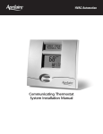
1
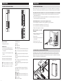
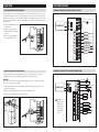
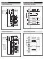
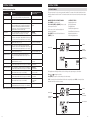
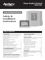
Home Comfort Control™
Model 8910
READ AND SAVE THESE INSTRUCTIONS
Safety &
Installation
Instructions
Table of contents
Installation
Thermostat installation location recommendations . .
Thermostat mounting . . . . . . . . . . . . . . . . . . . . . . . . . .
Equipment control module installation location
recommendations . . . . . . . . . . . . . . . . . . . . . . . . . . . . .
Equipment control module mounting . . . . . . . . . . . . . .
Thermostat wiring . . . . . . . . . . . . . . . . . . . . . . . . . . . . .
Remote temperature sensor (optional) . . . . . . . . . . . . .
Equipment control module wiring . . . . . . . . . . . . . . . .
Outdoor temperature sensor . . . . . . . . . . . . . . . . . . . . .
Optional wireless outdoor temperature sensor . . . . . .
Return air temperature sensor (optional) . . . . . . . . . . .
Leaving air temperature sensor (optional) . . . . . . . . . .
POWER & RESET OPTIONS
2
2
Power and reset options . . . . . . . . . . . . . . . . . . . . . . . 10
2
2
3
3
4
5
5
6
6
Equipment type selection switch (SW1) . . . . . . . . . . 11
Installer setup menu . . . . . . . . . . . . . . . . . . . . . . . . . . 11
Change system settings . . . . . . . . . . . . . . . . . . . . . . . 11
HVAC installer system settings table . . . . . . . . . . . 12-13
Indoor Air Quality system settings tables . . . . . . . . . 14
Air cleaning sytem settings table . . . . . . . . . . . . . . 14
Humidifier system settings table . . . . . . . . . . . . . . 14
Dehumidifier system settings table . . . . . . . . . . . . 15
Ventilation system settings table . . . . . . . . . . . . . . 16
System test menu . . . . . . . . . . . . . . . . . . . . . . . . . . 17-18
System test tables . . . . . . . . . . . . . . . . . . . . . . . . . 18-20
HVAC WIRING DIAGRAMS
Conventional heat/cool single transformer . . . . . . . . .
Conventional heat/cool two transformer . . . . . . . . . . .
Heat pump single transformer . . . . . . . . . . . . . . . . . . .
Heat pump two transformer . . . . . . . . . . . . . . . . . . . . .
7
7
8
8
Indoor Air Quality WIRING DIAGRAMS
Indoor Air Quality wiring with separate transformers . . . 9
Indoor Air Quality wiring with a single transformer . . . . . 9
Setup & Testing
References
Quick reference to controls & display . . . . . . . . . . 21-22
Troubleshooting . . . . . . . . . . . . . . . . . . . . . . . . . . . . 22-23
Error codes . . . . . . . . . . . . . . . . . . . . . . . . . . . . . . . . . 23
Home Comfort Control features . . . . . . . . . . . . . . . . . 23
Specifications . . . . . . . . . . . . . . . . . . . . . . . . . . . . . . . 24
Installation
Installation
Thermostat Installation location recommendations
Thermostat Wiring
Thermostat should be mounted:
Do not mount thermostat:
Wire specifications:
• On an interior wall, in a frequently occupied space.
• Behind doors, in corners or other dead air spaces.
18-24 gauge thermostat wire
• Approximately 5‘ above floor.
• At least 18” from outside wall.
• In direct sunlight, near lighting fixtures, or other
appliances that give off heat.
Installation notes:
• Thermostat can be mounted to a vertical junction box.
• On an outside or unconditioned area wall.
• In the flow of a supply register, in stairwells, or near
outside doors.
• On a wall with concealed pipes or ductwork.
1
• Ensure power at the HVAC equipment is off.
2
3
T1 T2
• Loosen screw terminals, insert stripped wire
and re-tighten.
• Push the excess wire back into the opening and plug the wall opening to prevent drafts.
1 – Connection to terminal 1 at equipment control module
Thermostat mounting
2 – Connection to terminal 2 at equipment control module
1.Remove the rear mounting plate from the thermostat.
3 – Connection to terminal 3 at equipment control module
2.Pull wires through the opening on the back of the thermostat.
T1 & T2 – Remote temperature sensor (optional)
3.Position and level the mounting plate of the thermostat on
wall and mark the hole locations with a pencil.
Remote temperature sensor (optional)
4. Drill 1/4” holes and insert supplied anchors (drywall only).
A remote temperature sensor can be used if the thermostat is to be mounted in a concealed location. A 8051 flush
mount or 8053 surface mount remote temperature sensor can be attached to the T1 and T2 terminals and mounted
in a recommended area. The remote sensor must be enabled in the installer set-up menu, and once enabled will
override the thermostat’s internal temperature sensor.
5. Place mounting plate over anchors, insert and tighten screws.
6.Seal wire entry holes to prevent drafts affecting temperature
readings.
Equipment Control Module Installation Location Recommendations
Note: Installer must touch a grounded metal object before handling the Equipment Control Module to avoid potential
loss of programs due to electrical discharge.
Remote temperature sensor should be
mounted:
• On an interior wall, in a frequently occupied
space.
• Approximately 5‘ above floor.
Equipment control module should be mounted:
Do not mount equipment control module:
• At least 18” from outside wall.
• In a location where the temperature will not exceed
140°F (60°C) or drop below 32°F (0°C).
• On foundation walls or on the HVAC equipment or
ductwork. These locations can cause moisture to
condense on the equipment control module.
• Using less than 300’ of wire.
Do not mount remote sensor:
• Behind doors, in corners or other dead air
spaces.
Equipment Control Module Mounting
The Equipment Control Module has the following features to simplify mounting and wiring and provide for a clean
and neat installation.
• Six (6) mounting holes. One on each corner and two centered top and bottom. Any combination of these holes may
be utilized. Mount the Equipment Control Module using 2 to 4 #8 screws appropriate for the mounting surface
substrate. (See Figure 2.)
• Wires can be routed through
the top, bottom, sides or back.
• In direct sunlight, near lighting fixtures, or
other appliances that give off heat.
1
2
3
T1 T2
• On an outside or unconditioned area wall.
• In the flow of a supply register, in stairwells,
or near outside doors.
• On a wall with concealed pipes or ductwork.
• Near 120 VAC lines.
• Nylon wire ties can be used
to secure wires in 10 places.
Installation Steps
1.Select mounting location.
2.Pull from bottom to remove
front cover. (See Figure 1.)
3.Mount base using 2 to 4 #8
screws (field supplied).
2
Figure 1
Figure 2
3
Installation
Installation
Equipment Control Module Wiring
Outdoor temperature sensor
Outdoor temperature can be measured by installing an 8052 sensor (included) to the ODT terminals and enabling the
outdoor sensor in the installer set-up menu. When an outdoor sensor is installed, the features below will be enabled.
In heat pump mode the outdoor temperature sensor can be used to efficiently utilize an air source heat pump:
• When the outdoor temperature is less than the Low Balance Point, the heat pump will be locked out and only
auxiliary heating will be used.
• When the outdoor temperature is higher than the High Balance Point, the auxiliary heating will be locked out and
only the heat pump will be used to provide heating.
Indoor Air Quality functions can use the outdoor temperature sensor to:
• Control humidification setpoint based on outdoor temperature to prevent condensation
• Lock out humidification for temperatures over 60°F or below -30°F.
• Lock out ventilation based on high and/or low outdoor temperatures.
• Display outdoor temperature on thermostat.
Outdoor temperature sensor should
be mounted:
• On side of building out of direct sunlight
(north side recommended).
• Above snow line.
• At least 3’ away from exhaust vents and
condensing lines.
• Using less than 300’ of wire.
Wire specifications:
C – 24VAC common
18-24 gauge thermostat wire
R – 24VAC
Installation notes:
• Ensure power at the HVAC equipment is off.
• Loosen screw terminals, insert stripped wire
and re-tighten.
• Use zip tie to route wiring through the wiring
channels.
1 – Connection to terminal 1 at thermostat
2 – Connection to terminal 2 at thermostat
• Do not route wires along 120 VAC lines.
RC – 24VAC Cooling
RH – 24VAC Heating
W – First stage heat (conventional)/auxiliary (heat pump)
W2 – Second stage heat (conventional)/ auxiliary (heat
pump)
W3/B – Third stage heat (conventional)/reversing valve
(heat pump)
Y – First stage cooling (conventional)/first stage compressor
(heat pump)
3 – Connection to terminal 3 at thermostat
Y2 – Second stage cooling (conventional)/second stage
compressor (heat pump).
RAT – Return air temperature sensor (optional)
LAT – Leaving air temperature sensor (optional)
Y3/0 – Third stage cooling (conventional)/reversing valve
(heat pump)
ODT – Outdoor temperature sensor (optional)
G – Fan
optional wireless Outdoor temperature sensor
For installations where it is difficult to wire the included 8052 outdoor temperature sensor, a Model 8056 wireless
outdoor temperature module can be used. The Model 8056 module has two radio units, one that is placed on the
equipment control module as shown below, and a second radio that is placed outside. See the Model 8056 Installation
Instructions for detailed directions regarding installation.
Outdoor Sensor
L – System fault indicator (heat pump only) (optional)
CEQ – 24VAC common from heat pump for system fault
indicator (optional)
HUM – Humidifier
DHno & DHcom – Normally open dehumidifier control
DHnc & DHcom – Normally closed dehumidifier control
VENT – Ventilation
EAC – Electronic Air Cleaner
4
5
Installation
HVAC WIRING DIAGRAMS
Return Air Temperature Sensor (Optional)
Conventional Heat/Cool Single Transformer (Use Jumper)
Return air temperature can be measured by attaching an 8052 sensor to the RAT terminals. The return sensor must
be enabled in the installer set-up menu. The return air temperature sensor provides protection in the event that the
equipment control module loses connection with the thermostat. In the event that the thermostat connection is lost,
the equipment control module will use the return air temperature sensor to maintain a temperature greater than 40°F
and less than 100°F.
1.Locate the Aprilaire Model 8052 sensor
in the return trunk.
C
THERMOSTAT
2.Mount the sensor according to the
installation instructions provided with
the sensor.
1
R
2
RC
3
RH
HC
3.Wire the sensor to the equipment
control module RAT terminals.
TRANSFORMER
HP
W
W
1st HEATING
W2
W2
2nd HEATING
W3
B
3rd HEATING
Y
Y
1st COMPRESSOR
Y2
Y2
2nd COMPRESSOR
Y3
O
3nd COMPRESSOR
G
G
FAN
L
C EQ
Leaving Air Temperature Sensor (Optional)
Conventional Heat/Cool Two Transformer (remove Jumper)
Leaving air temperature can be measured by attaching an 8052 sensor to the LAT terminals. The leaving air
temperature sensor measurement is displayed during the installer test for diagnostic purposes.
IMPORTANT
Do not mount the sensor in direct line-of-sight of the heat exchanger, cooling coils, or UV lights as this may cause
the sensor to report false temperature readings.
1. Locate the Aprilaire Model 8052 sensor in the supply trunk, after the heat exchanger and cooling coils. (See
shaded areas in figure below.)
C
THERMOSTAT
2.Mount the sensor according to the installation instructions provided with the sensor.
R
2
RC
3
RH
HC
3.Wire the sensor to the equipment control module LAT terminals.
1
LOCATE
SENSOR
IN SHADED
AREA.
1
R and C can be
powered from the
HVAC equipment
transformer or any
other constantly
powered 24VAC
source.
1
TRANSFORMER
COOLING TRANSFORMER
HEATING TRANSFORMER
HP
W
W
1st HEATING
W2
W2
2nd HEATING
W3
B
Y
Y
1st COMPRESSOR
Y2
Y2
2nd COMPRESSOR
Y3
O
3rd COMPRESSOR
G
G
FAN
L
C EQ
6
7
HVAC WIRING DIAGRAMS
Indoor Air Quality WIRING DIAGRAMS
Heat Pump Single Transformer (Use Jumper Wire)
Indoor Air Quality wiring with separate transformers
TRANSFORMER
C
THERMOSTAT
1
R
2
RC
HUM
HEAT PUMP TRANSFORMER
RH
3
DHno
HC
HP
W
W
1st HEATING
W2
W2
2nd HEATING
W3
B
REVERSING VALVE
Y
Y
1st COMPRESSOR
Y2
Y2
2nd COMPRESSOR
Y3
O
REVERSING VALVE
G
G
L
HUMIDIFIER
DEHUMIDIFIER
DHcom
FAN
FAULT DETECT
DHnc
VNT
EAC
NORMALLY
CLOSED DAMPER
PILOT RELAY FOR
120 VAC TO EAC
TRANSFORMER
TRANSFORMER
C EQ
Note: Outputs are 24VAC dry contact. Please see individual product installation instructions for more details.
Heat Pump Two Transformer (Remove Jumper Wire)
C
THERMOSTAT
1
R
2
RC
RH
3
HC
1
R and C can be
powered from the
HVAC equipment
transformer or any
other constantly
powered 24VAC
source.
HP
Indoor Air Quality wiring with a single transformer
1
TRANSFORMER
HEAT PUMP TRANSFORMER
HEATING TRANSFORMER
W
W
1st HEATING
W2
W2
2nd HEATING
W3
B
REVERSING VALVE
Y
Y
1st COMPRESSOR
Y2
Y2
2nd COMPRESSOR
Y3
O
REVERSING VALVE
G
G
L
FAN
FAULT DETECT
HUM
DHno
HUMIDIFIER
TRANSFORMER
DEHUMIDIFIER
DHcom
DHnc
VNT
EAC
8120 DAMPER
PILOT RELAY FOR
120 VAC TO EAC
C EQ
Note: Outputs are 24VAC dry contact. Please see individual product installation instructions for more details.
8
9
Power & Reset options
The equipment control module is powered from
24VAC. The thermostat is powered from the equipment
interface module and has a battery back-up option for
the clock.
The thermostat has a memory backup that saves the
thermostat settings in case of a power interruption.
The system settings will be retained but the clock will
reset after 90 seconds with no battery or equipment
control module power.
The reset button located under the battery cover can
be used to reset the thermostat to factory defaults. The
system settings will also be reset to default.
Setup & Testing
RESET
BUTTON
EQUIPMENT TYPE SELECTION SWITCH (SW1)
This Home Comfort Control has the option of being used
in heat pump or heat/cool systems. Switch SW1 located
on the back of the thermostat’s face is used to select this
option. This setting is displayed in the Installer System
Settings under Equipment Type.
SW1
HEAT/COOL
HEAT PUMP
HC
HP
Note: Home Comfort Control reboots within 10 seconds
after switch position is changed.
HC
HP
Installer setup menu
How to enter the installer setup menu AND SELECT EQUIPMENT TO SETUP:
In the Installer Setup, HVAC or Indoor Air Quality setup can be selected. If Indoor Air Quality setup is selected, the
user can then select to set up Air Cleaning, Humidification, Dehumidification or Ventilation.
Press [MODE] to set system to OFF.
Press
Press [MENU] to enter main menu.
Press [MENU] to exit.
Press and hold [SETUP] for seven seconds, [INSTALL
SETUP] appears.
Press [NEXT] to select option.
Press [INSTALL SETUP] to enter installer setup menu.
or
to adjust the option.
If IAQ (Indoor Air Quality) was selected, Press
or
to adjust the Outdoor Sensor setting or IAQ (Indoor
Air Quality) option.
Press [NEXT] to select Outdoor Sensor setting or IAQ
(Indoor Air Quality) option.
System Settings can now be changed.
Change System Settings
SETTING
DESCRIPTION
SETTING
OPTIONS
SETTING
NUMBER
Press [NEXT] or [BACK] to page through the settings.
Press
or
to adjust the setting.
Press [DONE] to save and exit, or [CANCEL] to exit
without saving.
The thermostat will discard changes and exit if nothing
is pressed within 60 seconds.
To reset the installer settings to the default, reset
the thermostat by pressing the [RESET] button for 5
seconds.
10
11
Setup & Testing
Setup & Testing
HVAC INSTALLER SYSTEM SETTINGS TABLE
HVAC INSTALLER SYSTEM SETTINGS TABLE (CONTINUED)
The following table contains the system settings and their details. Default settings are shown in bold. Some settings
are only available dependent upon the value of other settings.
12
Factory default setting (bold)
and setting range
System setting
Description
Factory default setting (bold)
and setting range
19. Fourth Stage Differential
4th stage differential.
1°F (0.5°C)
1°F to 9°F (0.5°C to 4.5°C)
System setting
Description
00. Equipment Type
Equipment type set by SW1.
Heat /Cool
Heat Pump
20. Heat Blast
Enables the Heat Blast feature.
Disable
Enable
01. Control Setup
Used to lockout heating or cooling outputs. (Only
available in Heat/Cool mode.)
Heat and Cool
Heat Only
Cool Only
21. Blast Offset
Amount of heating when Heat Blast is initiated.
3°F (2°C)
3°F to 5°F (2°C to 3°C)
22. Screen Lockout
02. Number of Stages
Number of equipment stages. (Three is only
available in Heat/Cool mode.)
One
Two
Three
Screen lockout level. (Override lockout by holding
[MENU] for 7 seconds.)
Off
Part
Full
23. Partial Lockout Type
03. Aux Heat Stages
Number of auxiliary heat equipment stages.
One
Two
Select lockout type. (Only available when screen
lockout is set to partial.)
Fan/Mode/Setpt
Fan/Setpoints
Setpoints Only
04. Temperature Scale
Set the thermostat to Fahrenheit or Celsius mode.
Fahrenheit
Celsius
24. Max Temp Setpoint
Change In Lockout
Select temperature setpoint limits. (Only available
when screen lockout is set to partial.)
3 degrees
0 to 20 degrees
05. Heat/Cool: Fan Control
in Heating
Heat Pump: Auxiliary
Equipment Type
Heat/Cool: Determines if the thermostat or
equipment controls the fan in heating.
Heat Pump: Auxiliary Equipment type.
Gas/Oil Heat (equipment controls fan)
Electric Heat (thermostat controls fan)
41. Max Dehum Setpoint
Change In Lockout
Select dehumidification setpoint limits. (Only
available when screen lockout is set to partial.)
5 Percent RH
0 to 15 Percent RH
25. Stage Rate
06. Extended Fan – Heat
Extends fan operation after heat call ends.
Disable
Enable (90 second extension)
Accumulation of equipment run time in equipment
staging determination.
1 = more rapid staging of equipment (comfort)
5 = slower staging of equipment (economy)
2
1 to 5 or “OFF” to ignore accumulated
run time.
07. Extended Fan – Cool
Extends fan operation after cool call ends.
Disable
Enable (90 second extension)
27. Progressive Recovery
Enable or disable progressive recovery.
Disable
Enable
08. Internal Temp Sensor
Offset
Field adjustment of internal temperature sensor.
0° (no offset applied)
-4°F to +4°F (-2°C to +2°C)
28. Low Balance Point
35. Internal RH Sensor Offset
Field adjustment of internal RH sensor.
0 (no offset applied)
-5% to +5%
Outdoor temperature low balance point. (This
option is only displayed if the outdoor sensor is
enabled.)
20°F (-6°C)
10°F to 50°F (-12°C to 9°C) or OFF to
ignore
29. High Balance Point
09. Auto Changeover
Enable or disable auto changeover mode.
Disable
Enable
Outdoor temperature high balance point. (This
option is only displayed if the outdoor sensor is
enabled.)
65°F (18°C)
40°F to 85°F(3°C to 18°C) or OFF to
ignore
26. Deadband
Auto Changeover mode deadband.
3°F (2°C)
2°F to 9°F (1°C to 5°C)
30. Program Format
Select weekly program format.
10. Remote Sensor
Select if remote sensor is attached.
No
Yes
7-Day (Mon, Tue, Wed, Thu, Fri, Sat, Sun)
5/1/1 (weekdays, Saturday and Sunday)
5/2 Weekdays (weekdays and weekends)
Non-Prog
32. E vents Per Day
Number of program events per day.
11. Outdoor Sensor
Select if outdoor sensor is attached or not.
No
Yes
Four
Two
33. R eset Service Reminders
35. Return Sensor
Select if return sensor is attached or not.
No
Yes
No
Yes
12. Compressor Min Off Time
Minimum off time for compressor protection.
5 minutes
1 to 5 minutes
Clears the Change Air Filter and HVAC and
Dehumidifier Service reminders if they are active
and resets the start date to the current date.
Clears the Change Water Panel reminder if it is
active. If the reminder is set to timed, the clock
will be reset.
13. Heating Min Off Time
Minimum off time for heating.
2 minutes
1 to 5 minutes
37. H
VAC Service Reminder
The period for displaying the “HVAC Service
Reminder” message.
Off
1 to 12 months or “Off” to disable
14. Equipment Min On Time
Minimum on time for heating and cooling.
2 minutes
1 to 5 minutes
38. Constant Backlight
Enable constant, low intensity backlight when
24VAC is present.
Disable
Enable
15. Auto Changeover Time
Minimum time between heating and cooling calls.
4 minutes
1 to 5 minutes
39. Backlight Intensity
Backlight intensity as a percentage of full on.
100 Percent
0 to 100 Percent
16. First Stage Differential
1st stage differential.
1°F (0.5°C)
1°F to 9°F (0.5°C to 4.5°C)
40. Auto Daylight Savings
Enable or disable auto daylight savings.
17. Second Stage Differential
2nd stage differential.
1°F (0.5°C)
1°F to 9°F (0.5°C to 4.5°C)
18. Third Stage Differential
3rd stage differential.
1°F (0.5°C)
1°F to 9°F (0.5°C to 4.5°C)
Off
March (second Sunday in March to the
first Sunday in November)
April (first Sunday in April to the last
Sunday in October)
13
Setup & Testing
Setup & Testing
Dehumidifier System Settings Table
Indoor Air Quality System SettingS Tables
The following tables contain the Indoor Air Quality system settings and their details. Default settings are shown in
bold. Some settings are only present dependent upon the value of other settings.
The use of an outdoor temperature sensor (recommended) enables additional Indoor Air Quality functionality. If the
outdoor temperature sensor was not enabled in the HVAC system settings, HVAC system setting 11, outdoor sensor,
will be presented prior to entering the Indoor Air Quality system settings.
System setting
Dehumidifier Control
Description
Selects method of dehumidification.(If set to none, no
other dehumidifier settings will be available.)
Humidity Setpoint Deadband
Select the minimum difference between the humidifier
and dehumidifier setpoints. (Only available if both a
humidifier and dehumidifier are installed. Available in
both set-ups.)
Selects if dehumidification is disabled during a cooling
call.
Select if dehumidification can turn on the fan.
Please refer to the Model 8910 Owner’s Manual for further information about Home Comfort Control features.
Air Cleaning System Settings Table
System setting
Air Cleaner Installed
Change Air Filter Reminder
Description
Selects if an air cleaner is installed. (If set to no, no other
air cleaning settings will be available.)
The period for displaying the “Change Air Filter” message.
Factory default setting (bold)
and setting range
No
Yes
Off
1 to 12 months or “Off” to disable
Humidifier System Settings Table
System setting
Humidifier Installed
Humidity Setpoint
Deadband
Humidifier Mode
Humidifier Operation
14
Description
Selects if a humidifier is installed. (If set to no, no other
humidifier settings will be available.)
Select the minimum difference between the humidifier and
dehumidifier setpoints. (Only available if both a humidifier
and dehumidifier are installed. Available in both set-ups.)
Selects auto or manual mode. Auto mode controls humidity
based on the humidity setting and outdoor temperature.
Manual mode controls humidity based on the %RH setpoint.
(Auto mode is only available if outdoor sensor is set to yes.)
Selects when humidification is allowed to occur relative to
heating and fan operation.
Change Water Panel
Reminder
Selects the when the “Change Water Panel” message is
displayed.
Reminder Month (Change
Water Panel Reminder set
to 1 per Season)
Change Water Panel Reminder set to 1 per Season:
Determines the month the “Change Water Panel” message
is displayed.
First Reminder Month
(Change Water Panel
Reminder set to 2 per
Season)
Change Water Panel Reminder set to 2 per Season:
Determines the first month the “Change Water Panel”
message is displayed.
Second Reminder Start
Month
Determines the second month the “Change Water Panel”
message is displayed. (Only available when Change Water
Panel Reminder set to 2 per Season.)
Factory default setting (bold)
and setting range
No
Yes
10 Percent RH
10 to 20 Percent RH
Auto
Manual
Lockout Dehumidifier During
Cooling
Dehumidifier Forces Fan
Dehumidifier Service
Reminder
Dehumidifier Overcooling
Limit
Dehumidify in Vacation
Mode
Vacation Dehumidifier Low
Temp Limit
The period for displaying the “Dehum Service
Reminder” message.
Selects the amount of overcooling that can occur for
dehumidification. (Only available if dehum control is
set to air conditioner.)
Selects if dehumidification with the air conditioner
is done in Vacation Mode. (Only available if dehum
control is set to air conditioner.
Sets the lowest temperature the air conditioner will
cool to meet RH setpoint in Vacation Mode. (Only
available if dehum control is set to air conditioner.)
Factory default setting (bold)
and setting range
None (no dehumidification installed)
Whole Home
Air Conditioner
10 Percent RH
10 to 20 Percent RH
No
Yes
No
Yes
Off
1 to 12 months or “Off” to disable
3°F (1.5°C)
1°F to 3°F (0.5°C to 1.5°C)
No
Yes
75°F (24°C)
70°F to 85°F (21°C to 29°C)
Note: Refer to manuals for humidifier, dehumidifier, air cleaner and ventilation products for recommended
installation and operation.
Heat Only
Heat or Fan
Forces Fan
Off
1 Per Season
2 Per Season
300 Hours
600 Hours
October
November
December
January
February
March
April
May
June
July
August
September
October
November
December
January
February
March
April
May
June
July
August
September
15
Setup & Testing
Setup & Testing
Ventilation System Settings Table
System test menu
System setting
Description
Factory default setting (bold)
and setting range
Fresh Air Vent Installed
Selects if ventilation is installed.
(If set to no, no other ventilation settings will be available.)
No
Yes
Fresh Air Forces Fan
Selects if ventilation forces the fan on.
No
Yes
The system test menu is used to test a system after installation. The outputs of the Home Comfort Control can be
manually activated to test their function. The instructions below show how to enter the test mode and turn outputs
on and off.
How to enter the system test menu:
SYSTEM TEST STEPS
Press [MODE] to set system to off.
Heating equipment test
Cooling equipment test
Fan equipment test
Humidification equipment test
Dehumidification equipment test
Ventilation equipment test
Air Cleaning equipment test
Selects if ventilation is configured through the ASHRAE setup
or Timed. If ASHRAE setup is selected, the hourly ventilation
time will be calculated using the ASHRAE recommendations.
If Timed set-up is selected, the hourly ventilation time will be
determined based on the Fresh Air Time value.
Timed
ASHRAE
Fresh Air Time
Selects how many minutes per hour that ventilation will be
active. (Only available if fresh air setup is set to timed.)
30 MIN/HR
0 to 60 MIN/HR
High Limit Outdoor
Temp
Selects if ventilation is disabled if the outdoor temperature
exceeds the outdoor high limit. (Only available if fresh air setup
is set to timed and an outdoor temperature sensor is installed.)
No
Yes
Outdoor High Limit
Sets the high temperature limit for ventilation. (Only available if
high limit outdoor temp set to yes.)
100°F (38°C)
90°F to 100°F (32°C to 44°C)
Low Limit Outdoor Temp
Selects if ventilation is disabled if the outdoor temperature
exceeds the outdoor low limit. (Only available if fresh air setup
is set to timed and an outdoor temperature sensor is installed.)
No
Yes
Outdoor Low Limit
Sets the low temperature limit for ventilation. (Only available if
low limit outdoor temp set to yes.)
10°F (-7°C)
-10°F to 30°F (-29°C to -1°C)
High Limit Indoor RH
Selects if ventilation is disabled if the indoor RH exceeds
the indoor RH limit. (Only available if fresh air setup is set to
timed.)
No
Yes
Indoor RH Limit
Sets the high indoor RH limit for ventilation. (Only available if
high limit indoor RH is set to yes.)
60%
50% to 70%
Number of Bedrooms
Selects the number of bedrooms to be used for the ASHRAE
calculation. (Only available if fresh air setup is set to ASHRAE.)
3 Bedrooms
1 to 6 Bedrooms
Number of Occupants
Selects the number of occupants to be used for the ASHRAE
calculation. (Only available if fresh air setup is set to ASHRAE.)
4 Occupants
1 to 10 Occupants
Home Size
Selects the home size to be used for the ASHRAE calculation.
(Only available if fresh air setup is set to ASHRAE.)
2500 SQ FT
1000 to 5000 SQ FT
Each equipment test will begin with the selection of turning on the output or stage as shown below.
Fresh Air CFM
Selects the ventilation CFM to be used for the ASHRAE
calculation. (Only available if fresh air setup is set to ASHRAE.)
60 CFM
30 to 200 CFM
Select Climate
Selects the climate to be used for the ASHRAE calculation.
(Only available if fresh air setup is set to ASHRAE.)
Normal
Very Hot/Humid
Very Cold
Press [NEXT] to accept the selection and proceed to the next step.
ASHRAE Cycle Time
Displays the Fresh Air Time calculated by the ASHRAE
standard. (Only displayed if fresh air setup is set to ASHRAE.)
Minutes/Hour
Fresh Air Setup
Press and hold [FAN] and [MODE] for three seconds
to enter system test mode.
The first screen of the installer test displays the
equipment configuration.
Press [NEXT] to enter the first installation test or
[CANCEL] to exit.
Humidity
Temperature
Outdoor Temperature Equipment Configuration
Press
or
to change the selection.
If YES is selected, the Home Comfort Control will test the corresponding output. If NO is selected, the Home
Comfort Control will proceed to the next step.
Note: In ASHRAE set-up temperature and humidity limits are disabled.
Humidity
Temperature
Equipment Test Selection
Outdoor Temperature Test to be run
16
17
Setup & Testing
Setup & Testing
System test menu (CONTINUED)
System test TABLES (CONTINUED)
While the equipment test is active the corresponding test information will be shown.
Heat Pump Heating Equipment Test (Electric Heat)
Press [NEXT] to accept the selection and proceed to the next test selection.
Compressor
Stages
Aux
Stages
1
1
1st Stage Test
1
1
2nd Stage Test
2
1
1st Stage Test
ON
ON
2
1
2nd Stage Test
ON
ON
ON
ON
2
1
3rd Stage Test
ON
ON
ON
ON
ON
1
2
1st Stage Test
ON
ON
ON
1
2
2nd Stage Test
ON
ON
ON
ON
1
2
3rd Stage Test
ON
ON
ON
ON
2
2
1st Stage Test
ON
ON
2
2
2nd Stage Test
ON
ON
ON
ON
ON
ON
ON
ON
ON
ON
ON
W
W2
ON
B
Y
ON
ON
Y2
O
ON
G
ON
ON
ON
Humidity
Temperature
Outdoor Temperature ON
Output StatuS
Equipment Test Selection
Test that
is active
Leaving Air Temperature
2
2
3rd Stage Test
ON
2
2
4th Stage Test
ON
Compressor
Stages
Aux
Stages
1
1
1st Stage Test
1
1
2nd Stage Test
ON
ON
ON
ON
System test TABLES
Heat Pump Heating Equipment Test (Gas Heat)
Heat / Cool Heating Equipment Test
Heat Type
18
W
W2
Gas
1st Stage Test
ON
Gas
2nd Stage Test
ON
ON
Gas
3rd Stage Test
ON
ON
Electric
1st Stage Test
ON
Electric
2nd Stage Test
ON
ON
Electric
3rd Stage Test
ON
ON
W3
Y
Y2
Y3
G
W
W2
ON
B
Y
ON
ON
Y2
O
G
ON
ON
ON
ON
2
1
1st Stage Test
ON
ON
ON
2
1
2nd Stage Test
ON
ON
ON
2
1
3rd Stage Test
1
2
1st Stage Test
1
2
1
2
2
2
1st Stage Test
ON
ON
2
2
2nd Stage Test
ON
ON
ON
ON
2nd Stage Test
ON
ON
3rd Stage Test
ON
ON
ON
ON
ON
ON
2
2
3rd Stage Test
ON
2
2
4th Stage Test
ON
ON
ON
ON
ON
ON
ON
ON
ON
ON
ON
19
Setup & Testing
Quick Reference to controls & Display
System test TABLES (CONTINUED)
Home Screen
ROOM TEMPERATURE
Heat / Cool Cooling Equipment Test
W
W2
W3
Y
Y2
1st Stage Test
ON
2nd Stage Test
ON
ON
3rd Stage Test
ON
ON
Y3
G
ON
ON
ON
ON
Heat Pump Cooling Equipment Test
W
W2
B
Y
1st Stage Test
ON
2nd Stage Test
ON
Y2
ON
O
G
ON
ON
ON
ON
Fan Equipment Test
W
W2
W3/B
Y
Y2
Y3/O
G
ON
Current DAY
OUTDOOR TEMPERATURE
ROOM RELATIVE HUMIDITY
TEMPERATURE SETTING
FAN MODE
BUTTON
Air Cleaning Button (Enters EVENT-BASED™ Air
Cleaning Control Screen)
FAN MODE
SETTING
Humidity Control Button (Enters Humidity Control Screen)
SYSTEM MODE
BUTTON
Fresh Air Button (Enters Ventilation Control Screen)
SYSTEM MODE
SETTING
IndicatorS show through housing
Temperature ADJUSTMENT
EQUIPMENT
STATUS
HEAT PUMP ONLY
Emergency heat or AUXILIARY HEAT (RED)
System FAULT (YELLOW)
MESSAGE
CENTER
MAINTENANCE REMINDER
(YELLOW FLASHING)
(SCROLLING TEXT)
HOLD BUTTON
(SETS OR CLEARS HOLD)
Humidification Equipment Test
HUM
DHNO/DHCOM
VENT
EAC
ON
G
LOW BATTERY INDICATOR
ON
CURRENT TIME & DATE
HEAT BLAST BUTTON
MAIN MENU BUTTON
Note: Backlight is activated with first button press and automatically turns off.
Dehumidification Equipment Test
HUM
DHNO/DHCOM
VENT
EAC
ON
G
ON
MAIN MENU
Ventilation Equipment Test
HUM
DHNO/DHCOM
VENT
EAC
ON
G
ON
Ventilation Equipment Test
HUM
DHNO/DHCOM
VENT
EAC
G
ON
ON
SET VACATION HOLD
(HOLD–TO TIME AND DATE)
SET SCHEDULE
BUTTON
SET CURRENT
TIME AND DATE
CLEAN SCREEN
(LOCKOUT TOUCH
SCREEN FOR 30
SECONDS)
DONE BUTTON
(EXIT MENU)
USER SYSTEM SETTINGS
20
21
Quick Reference to controls & Display
Troubleshooting
Equipment Control Module LEDs
Heat/cool both on at same time
POWER/STATUS – On solid during normal operation. Flashes
when connection to the thermostat is lost and at power-up while
the thermostat connection is being established.
HEATING – On when heating outputs are active.
“HEATING” is not displayed
• Check SW1 (Equipment Type), to make sure it is set
to match the installed heating/cooling equipment.
• Check Installer System Setting number 05
(Control Setup) is set correctly.
• Check to make sure heating and cooling wires are
not shorted together.
• Change the System Mode to Heat, and set
the temperature level above the current room
temperature.
COOLING – On when cooling outputs are active.
Heating equipment is running in
cool mode
FAN – On when fan output is active.
HUMIDIFIER – On when humidifier output is active.
• Check SW1 (Equipment Type), to make sure it is set
to match the installed heating/cooling equipment
(see page 11).
DEHUMIDIFIER – On when dehumidifier output is active.
VENTILATION – On when ventilation output is active.
AIR CLEANING – On when air cleaner output is active.
“COOLING” is not displayed
• Check Installer System Setting number 05
(Control Setup) is set correctly.
• Change the System Mode to Cool, and set
the temperature level below the current room
temperature.
Error Codes
If the thermostat enters an error mode, all outputs are turned off. The thermostat attempts to recover every 10 minutes.
If the error does not clear, use the reset button. This will return all settings back to factory default.
Error code
Troubleshooting
Display is blank
If Power LED not illuminated at the equipment control
module check the following.
• Check circuit breaker and reset if necessary.
• Make sure power switch at heating & cooling
system is on.
• Make sure furnace door is closed securely.
Heating system does not respond
(“HEATING” appears on screen)
• Check for 24VAC at the equipment on the secondary
side of the transformer between power and
common. If voltage is not present, check the heating
equipment to find the cause of the problem.
• Check for 24VAC between the heat terminal (W)
and the transformer common. If 24VAC is present,
the Home Comfort Control is functional. Check the
heating equipment to find the cause of the problem.
• Check for loose or broken wires between the Home
Comfort Control and the heating equipment.
Cooling system does not respond
(“COOLING” appears on screen)
• Check for 24VAC at the equipment on the secondary
side of the transformer between power and
common. If voltage is not present, check the cooling
equipment to find the cause of the problem
• Check for 24VAC between the cooling terminal (Y)
and the transformer common. If 24VAC is present,
the Home Comfort Control is functional. Check the
cooling system to find the cause of the problem.
• Check for loose or broken wires between the Home
Comfort Control and the cooling equipment.
Fan does not turn on in a call for heat
• Check System Setting 09 (Fan Control), to make sure
the fan control is properly set to match the type of
system.
Heat pump issues cool air in heat mode,
or warm air in cool mode
• Check wiring at the terminal block to confirm the
reversing valve is connected to the proper terminal.
O is active in cooling and B is active in heating.
22
Message
01
Error Description
Open temperature sensor circuit
“SENSOR ERROR”
02
Shorted temperature sensor circuit
03
“EEPROM ERROR”
Error in permanent memory
05
“LOST SYSTEM CONNECTION”
Thermostat lost connection to equipment interface module
HOME COMFORT CONTROL™ Features
• Indoor air quality control.
– Humidification automatic or manual control.
– Dehumidification.
– Event-Based™ air cleaning.
– Ventilation with temperature and humidity limits.
• Temperature control.
• Heat Blast™ raises the room temperature 3°F to 5°F.
• Support for optional wireless outdoor temperature
sensor.
• Large touch screen with adjustable backlight –
constant backlight option available.
• Front battery door access for fast, easy replacement.
• Displays room temperature, room humidity,
temperature setting, and optional outdoor temperature.
• Air filter, humidifier, dehumidifier, and HVAC service
reminders.
• Programmable fan control with fan circulation mode.
• Easy to use temperature control can override program
schedule at any time.
• Progressive recovery ensures proper temperature at
the start of a program event.
• Message center provides feedback and instructions.
• Built in compressor protection prevents damage to
your equipment.
• 7 day programmability or separately programmable
weekday/weekend schedules.
• System test mode.
• Thermostat can be removed from the wall for easy
programming (batteries must be installed).
23
Specifications
Environment
Temperature (Shipping)
-30° to 150°F (-34° to 65°C)
Temperature Thermostat (Operating)
32° to 120°F (0° to 48°C)
Temperature Equipment Control Module (Operating)
32° to 158°F (0° to 70°C)
Relative humidity
Operating: 5% to 90% R.H. (non-condensing)
Electrical
Operating voltage
24VAC (18 – 30VAC)
Current
Maximum: 2.5A (total), 1.0A (single output)
Maximum surge current: 5A
Battery back-up
AA size alkaline battery x 2
Control
Outdoor, Remote, Leaving and Return temperature sensor
Maximum distance: 300 feet
Room temperature measurement
Display range: 32° to 99°F (0° to 40°C)
Return and Leaving temperature measurement
Display range: -20° to 160°F (-30° to 71°C)
Outdoor temperature measurement
Display range: -20° to 130°F (-30° to 55°C)
Setpoint temperature range
Heat: 40° to 90°F (4° to 32°C)
Cool: 50° to 99°F (10° to 37°C)
Setpoint humidity range
Humidification: 10% to 50% R.H.
Dehumidification: 50% to 90% R.H.
P.O. Box 1467 • Madison, WI 53701-1467 • Phone: 800/334-6011 • Fax: 608/257-4357
www.aprilairepartners.com
61000850 12.11
B2205646A
24
Patent Pending
© 2011 Aprilaire – A division of Research Products Corporation