1
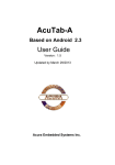
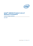
AcuPanel CV12
User Manual
AcuPanel 12CV
User Manual
Version 7.1
Acura Embedded Systems Inc.
AcuPanel CV12
User Manual
INDEX
Table of Contents ........................................................................ 2
Chapter 1 General Information .................................................. 3
1.1. Introduction ............................................................................3
1.2. Features ..................................................................................3
1.3. Specification ...........................................................................3
1.3.1. Technical Specification ....................................................... 3
1.3.2. Display ............................................................................. 3
1.3.3. Touch Screen ..................................................................... 4
1.3.4. I/O Interface ........................................................................ 4
1.3.5. AcuraVision Surveillance Solution ......................................... 4
1.3.6. Power .................................................................................. 4
1.3.7. Environment......................................................................... 4
1.3.8. Material ............................................................................... 4
1.3.9. Software .............................................................................. 4
1.3.10. Certifications ..................................................................... 5
1.4. Physical Dimensions ............................................................5
1.5. Assembling the panel PC .....................................................7
1.6. Enclosed Parts ......................................................................8
Chapter 2 System Setup ............................................................ 9
2.2. Installation Procedures .........................................................10
2.2.1. Connecting the power cord ...................................................10
2.2.2. Connecting the keyboard and mouse ...................................10
2.2.3. Switching on the power .........................................................11
2.4. Installing System Software and AcuraVision Solution ......11
Chapter 3 Using the Panel PC ..................................................... 11
3.1 Introduction .................................................................................11
3.2 Using the USB Mouse and Keyboard .........................................11
3.3 Using the Serial Ports (COM) .....................................................12
3.4 Using the USB Ports ...................................................................12
3.5 Using the LAN Port .....................................................................12
3.6. Using the DVR ...........................................................................13
3.7. Touch screen .............................................................................13
Chapter 4 The BIOS Setup Program ........................................... 13
4.1. CMOS Setup Utility ....................................................................13
4.2. Standard CMOS Features .........................................................13
4.3. Advanced BIOS Features ..........................................................14
4.4. Chipset Feature .........................................................................14
4.5. Boot Features ............................................................................15
4.6. Security Management Setup .... ................................................15
4.7. Save & Exit Setup .....................................................................15
2.1. Exploring AcuPanel12 ...........................................................9
Warnings ...……..…………………….…...…………………………... 16
2
AcuPanel CV12
User Manual
Chapter 1 General Information
1.1. Introduction
AcuPanel12CV is an Intel® Cedar Trail Dual Core 1.6 Ghz +Chipset: Intel® NM10 processor based Panel PC with a bright 10.4”/12.1" LCD
display. This powerful CPU and Intel® GMA3600 with a 400 MHz Graphics Core bring the most dynamic applications to life without sacrifices
to any industrial reliability. Delivering a variety of connectivity features, built-in USB, 4 Channels DVR socket, and robust capacity of 2.5” SATA
HDD, it is ideal for an all-around mobile surveillance system with AcuraVsion Solution performance. Furthermore, AcuPanel12CV is equipped
with fan less and no-ventilation-hole design, full IP67 featured with dustproof, waterproof, rugged aluminum enclosure and anti-collision
function, the durable AcuPanel12CV is suitable for any critical environment based on Class1 and Division 2 certificate.
1.2. Features
The AcuPanel12CV is a flexible, multi-functional flat panel PC. With following specifications that can be applied in diverse operational
environments and implemented in various applications.
•
•
•
•
•
•
•
•
•
•
•
Rugged Aluminum Enclosure and Fan less Design
No ventilation Hole
Full IP67-Dustproof and Waterproof
Wide Temperature Operating Capability
Indoor/outdoor Environment
Stand/Cabinet/VESA (Optional)
Anti-vibration (MIL-STD-810G)
Anti-shock (MIL-STD-810G IEC 60068-2-27) System Design
Removable / Anti-vibration HDD Design
Board Wide Range DC to DC Power
Design Support 12V Input
1.3. Specification
The AcuPanel12CV is a flexible, multi-functional flat panel PC. With following specifications that can be applied in diverse operational
environments and implemented in multi-faceted applications.
1.3.1. Technical Specification
•
•
•
•
•
•
•
•
CPU: Embedded Intel® Cedar Trail Dual Core 1.6 Ghz +Chipset: Intel® NM10
Memory: 1 x 800 MHz SO-DIMM DDR3/DDR3L(1.35V) supports up to 4 GB
Graphics Engine: Intel® GMA3600 with a 400 MHz Graphics Core
BIOS: UEFI BIOS
Storage: 1 x Internal 2.5" SATA HDD interface SSD, DOM, CF,
Wide Operating temperature HDD (Optional items)
Watchdog Timer: Software programmable supports :1 sec.~255 min reset.
H/W Status Monitor: Monitoring system temperature, voltage, and cooling fan status.
1.3.2. Display
•
•
•
•
Display Type:10.4”/ 12.1" Color TFT LCD or LED
Support Dual Display
Max Resolution: 800 x 600 pixels / 1024 x 768 pixels
Brightness: 1000 cd/m²
•
•
•
•
Touch Screen Type: Five-wire Analog Resistive
Max Colors: 16,194,277 color
Viewing Angle: 12.1" 80° (left), 80° (right), 80° (up), 80° (down)
Lamp Life Time: 50,000 hours
3
AcuPanel CV12
User Manual
1.3.3. Touch Screen
•
•
•
Touch Screen type: 5-wire Analog resistive type
Light Transmission: 80%
Durability (Touch lifetime): 35 million
1.3.4. I/O Interface
•
•
•
•
•
•
Serial Port: 1 x Serial port (COM:RS-232)
DVR Port: 1 x 4 channels DVR
USB Port: 2 x USB 2.0 ports
LAN Port: 1 x RJ45 Connector for 10/100 Base T Ethernet (ASF2.0 support)
Front LED: PWR / HDD
Switch: Power button
1.3.5. AcuraVision Surveillance Solution
Mobile Surveillance Software with Flow Count, Virtual Fence Detection, Secure Zone detection , Left/Missing Detection and
Flaming/Smoking Detection (Optional).
1.3.6. Power
•
•
•
•
•
Power Input Voltage: Support wide range DC 12V input voltage
Power Adapter: AC to DC 100-240VAC, DC19V / 3.42A, 65W (Optional)
Power consumption: 35W MAX
Power Button: 1 x Power Button
LED: Power / HDD LEDs
1.3.7. Environment
•
•
•
•
•
•
•
•
•
•
Dimensions: 317 x 248 x 68 mm
Temperature: Operating: -40°C ~ 65°C for SSD, DOM, CF, Wide temperature HDD; Operating: 0°C ~ 50°C for Normal HDD /
Storage: -20°C ~ 70°C HDD/LCD wide temperature
Humidity: 5% ~ 95% RH, (MIL STD 810G, Method 507.5 (Non-Operating)
EMI/EMS: Meet the CE and FCC class B and VCCI regulation.
Other function: Support USB device boot up (FDD,HDD,CD-ROM)
IP: IP67 waterproof and dustproof (IEC 60529)
RoHS: RoHS Compliant
Vibration (MIL-STD-810G Method 514.6 Procedure I, Category 20, Fig 514.6C-1, Fig 514.6C-2, Fig 514.6C-3(Operating)).
Shock (MIL-STD-810G Method 516.6)
1.3.8. Material
•
•
•
Front chassis material: Aluminum Front Bezel
Rear chassis material Aluminum Enclosure
Overlay material: PE Film
1.3.9. Software
•
OS Support :Microsoft Windows Professional for Embedded, XP or WIN7 x32bits Embedded.
•
Surveillance Solution: AcuraVision Mobile Surveillance Solution Designed by Acura Embedded Systems Inc.
4
AcuPanel CV12
User Manual
1.3.10. Certifications
1.4. Physical Dimensions
AcuPanel12CV is equipped with fanless and no-ventilation-hole design and is durable to suit any critical environment. The following drawing
shows you detailed information for the dimensions.
5
AcuPanel CV12
User Manual
Dimensions (units in mm)
6
AcuPanel CV12
User Manual
1.5. Assembling the panel PC
The procedure for assembling the panel PC is identified by following
drawing. Please follow the instruction below for panel mounting.
7
AcuPanel CV12
User Manual
1.6. Enclosed Parts
ITEM
PARTS
QTY
1
ACUC05-DVR-1
ACUC06-DVRE-WP-6
1
ACUC03-LAN-WP-6
1
ACUC02-Serial-WP-6
1
ACUC01-USB-WP-6
2
ACUC04-Power-WP-6
1
Screw-01
4
Screw-02
6
8
SPEC
4 Channels DVR Cable
DVR Waterproof
Extension Cable
RJ45, L=1.8M
DSUB, L=1.8M
USB, L=1.8M
DC Extension,
L=1.8M
M4*1.0+15PF-SUS
M6*1.0+15PF-SUS
AcuPanel CV12
User Manual
Chapter 2 System Setup
2.1. Exploring AcuPanel 12CV
Before starting to set up the panel PC, take familiar with the locations and purposes of controls, drives, connectors and ports, which are
illustrated in the figures below. When placed upright on the desktop, the front panel of the panel PC appears as shown in Figure 2.1.
The bottom side of the AcuPanel 12CV is equipped the I/O as described below.
1. LAN Port 2. USB2.0 3. USB2.0 4. RS-232/422/485 5. DVR Port 6. DC IN
•
LAN Port
An internal 10Base-T/100Base-TX Ethernet LAN module connects your Panel PC to other computers/networks through a local area
network (LAN).
•
USB Ports (x2)
The Universal Serial Bus (USB) port allows you to connect USB 2.0-compliant devices (for example, printers, scanners and so on) to your
Panel PC.
•
COM Port
Lets you connect a 9-pin external serial device such as a modem, mouse, or other serial devices.
•
DVR Port
Lets you connect a DVR Waterproof Extension Cable and 4 Channels DVR Cable which connect with CCTV or IP cameras' devices.
•
DC IN
Lets you connect the AC power adapter in supplying continuous power to AcuPanel12CV.
2.2. Installation Procedures
Your Panel PC is designed and pre-configured for easy setup and use. This section describes the installation steps you should follow to get
the system running as quickly as possible.
9
AcuPanel CV12
User Manual
2.2.1. Connecting the power cord
To connect the power cord:
1. Connect the DC extension cable plug to the computer’s Power Supply Connector.
2. Connect the DC extension cable wires to the corresponding positive and negative terminals on the DC power supply.
3. Turn on the DC power supply.
HAZARD OF ELECTRIC SHOCK, EXPLOSION OR ARC FLASH
•
•
•
•
•
Remove all power from the device prior to installing or removing any accessories, hardware, or cables.
Always use a properly rated voltage sensing device to confirm power is off.
Unplug the power cable from both the Panel PC and the power supply.
Replace and secure all covers or elements of the system before applying power to the unit.
Use only the specified voltage when operating the Panel PC. The DC unit is designed to use 12 - 24 VDC. Always check whether
your device is AC or DC powered before applying power.
Failure to follow these instructions will result in death or serious injury.
Connect the equipment to a properly grounded safety extra low voltage (SELV) with Limited Power Source (LPS). The power source is a
secondary circuit that is designed so that normal and single fault conditions do not cause the voltages to exceed a safe level.
2.2.2. Connecting the keyboard and mouse
A keyboard is an input device; a mouse is a pointing device. Please connect these two devices as graphics shown below to interact with your
panel PC.
10
AcuPanel CV12
User Manual
2.3.3. Switching on the power
The Power button is found on the left bottom on the rear side of the Panel PC. Press the Power button to start your panel PC and check that
the Power LED lights on to green on the front panel.
2.4. Installing System Software and AcuraVision Solution
The operating system is the software foundation for your Panel PC. It is the platform for all your software application programs to run on. The
most popular operating system today is Microsoft® Windows® XP or Microsoft® Windows® 7x32 bits. AcuPanel12CV comes with an
operating system pre-installed and needs only to be setup and configured during initial use.
Chapter 3 Using the Panel PC
Your panel PC is designed and pre-configured for easy setup and use. This chapter describes the installation steps you should follow to get
the system up and running as quickly as possible.
3.1 Introduction
This chapter describes the basic features and procedures for using the panel PC. It includes the I/O ports connecting and the touch screen
operation.
3.2 Using the USB Mouse and Keyboard
To install a full-size desktop keyboard and mouse with the panel PC, please follow the instructions below:
1. Turn off the panel PC.
2. Attach the USB keyboard and mouse to the USB ports.
3. Turn on the panel PC.
11
AcuPanel CV12
User Manual
3.3 Using the Serial Ports (COM)
There are one serial COM ports on the bottom. It is simple to attach a serial device to the panel PC, like an external modem or mouse. Please
follow these instructions below for connecting :
1. Be sure the panel PC and any other peripheral devices that are connected to the panel PC are turned off.
2. Attach the interface cable of the serial device to the panel PC's serial port. If necessary, attach the other end of the interface cable to the
serial device. Fasten any retaining screws.
3. Turn on any other peripheral devices which are connected to the panel PC, and then turn on the panel PC.
4. Refer to the manual(s) which accompanied any serial device(s) for instructions on configuring the operating environment to recognize the
device(s).
5. Run the BIOS setup program and configure the jumper settings to change the mode of the COM ports.
3.4 Using the USB Ports
An external USB device may be connected to the system through the
4-pin USB ports located on the bottom side of the system unit.
1. Connect the external device to the system.
2. The USB ports support hot plug-in connections. Install the device driver before using the device.
3.5 Using the LAN Port
This unit comes with an internal 10Base-T/100Base-TX LAN module that connects your panel PC to other computers/networks through a local
area network (LAN) and supports data transfer rates at 10Mbps and can be up to 100Mbps. The 10Base-T standard also called Twisted Pair
Ethernet is connected with RJ-45 connectors. The 100Base-TX is based on the older Ethernet standard. Because it is 10 times faster than
Ethernet, it is often referred to as Fast Ethernet. The built-in LAN module provides a standard RJ-45 connector.
To connect the twisted-pair cable to your LAN port:
1. Connect one end of the cable into the network wall outlet or HUB.
2. Connect the other end of the cable into the Panel PC RJ-45 LAN port.
12
AcuPanel CV12
User Manual
3.6 Using the DVR Port
This unit comes with a four channels DVR module that connects AcuPanel12CV to CCTV cameras through DVR waterproof extension cable
and four channels DVR cable, Also supports IP cameras data transfer rates at 10Mbps and can be up to 100Mbps. The 10Base-T standard
also called Twisted Pair Ethernet is connected with RJ-45 connectors. The 100Base-TX is based on the older Ethernet standard. Because it is
10 times faster than Ethernet, it is often referred to as Fast Ethernet. The built-in LAN module provides a standard RJ-45 connector.
To connect the twisted-pair cable to your LAN port:
1. Connect one end of the cable into the network wall outlet or HUB.
2. Connect the other end of the cable into the Panel PC RJ-45 LAN port.
18
13
3.7. Touchscreen
AcuPanel12 is designed using Color Active Matrix LCD technology with a high quality touch sensitive surface. The touch screen is a display
that can detect the presence and location of a touch within the display area by a finger, hand or other passive objects, such as a stylus. It
enables one to interact with what is displayed directly on the screen, rather than indirectly with a mouse.
With its adjustable, yet rigid backbone, the touch screen responds to fingertip input in place of a mouse and is highly resistant to solvents and
chemicals found in industrial environments. It lets one do so without requiring any intermediate device, The display is sealed along the panel
surface to prevent liquids from dripping into the unit under normal use.
Chapter 4 The BIOS Setup Program
This system comes with a chip from Award BIOS that contains the ROM Setup information for your system. (This chip serves as an interface
between the processor and the rest of the system components.) This section explains the information contained in the Setup program and tells
you how to modify the settings according to your system configuration.
4.1. CMOS Setup Utility
The Setup utility program allows updates to the system configuration settings. The BIOS setup values will be saved in the CMOS. It is
executed when you change the system configuration, you change the system backup battery, or the system detects a configuration error and
asks you to run the Setup program. Use the arrow keys to select, and press Enter to run the selected program.
4.2.Standard CMOS Features
13
AcuPanel CV12
User Manual
This option lists all the features for standard CMOS configuration.
4.3.Advanced BIOS Features
This option lists all the features for advanced BIOS configuration.
4.4.Chipset Features
This option lists all the features for chipset configuration.
14
AcuPanel CV12
User Manual
4.5.Boot Features
This option lists all onboard bootable devices.
4.6.Security Management Setup
Set Administrator/User Password, These options let you create, change or disable the passwords.
4.7.Save & Exit Setup
This option lets you saves all changes to CMOS while running the BIOS setup program and exit from the system setup program.
15
AcuPanel CV12
User Manual
WARNINGS
THIS EQUIPMENT IS SUITABLE FOR USE IN CLASS I, DIVISION 2, GROUPS (AS APPLICABLE) OR NON-HAZARDOUS LOCATIONS
ONLY.
WARNING - EXPLOSION HAZARD - SUBSTITUTION OF COMPONENTS MAY IMPAIR SUITABILITY FOR CLASS I, DIVISION 2.
WARNING - EXPLOSION HAZARD - DO NOT REPLACE UNLESS POWER HAS BEEN SWITCHED OFF OR THE AREA IS KNOWN TO BE
NON-HAZARDOUS.
WARNING - EXPLOSION HAZARD – DO NOT DISCONNECT EQUIPMENT UNLESS POWER HAS BEEN SWITCHED OFF OR THE AREA
IS KNOWN TO BE NON-HAZARDOUS.
WARNING: DO NOT REMOVE OR REPLACE WHILE CIRCUIT IS LIVE UNLESS THE AREA IS KNOWN TO BE FREE OF IGNITIBLE
CONCENTRATIONS OF FLAMMABLE SUBSTANCES.
WARNING: EXPOSURE TO SOME CHEMICALS MAY DEGRADE THE SEALING PROPERTIES OF MATERIALS USED IN THE
FOLLOWING DEVICES.
WARNING: EXPLOSION HAZARD. DO NOT REMOVE OR REPLACE LAMPS, FUSES OR PLUG-IN MODULES (AS APPLICABLE)
UNLESS POWER HAS BEEN DISCONNECTED OR THE AREA IS KNOWN TO BE FREE OF IGNITIBLE CONCENTRATIONS OF
FLAMMABLE GASES OR VAPORS.
WARNING: EXPLOSION HAZARD. DO NOT DISCONNECT WHILE THE CIRCUIT IS LIVE OR UNLESS THE AREA IS KNOWN TO BE
FREE OF IGNITIBLE CONCENTRATIONS.
WARNING: SUBSTITUTION OF THE FOLLOWING COMPONENTS; POWER SUPPLY, POWER CABLE OR POWER CONNECTOR MAY
IMPAIR SUITABILITY FOR DIVISION 2.
With the unique set of products, Acura Embedded Systems remains committed to its goal of providing trouble-free and customer-friendly
service. A special customer service unit has been set up specifically to cater to our esteemed customers' needs.
Technical Support:
contact your Salesperson or
[email protected]
Mailing address:
Acura Embedded Systems Inc.
Unit #1, 7711-128th Street,
Surrey, BC V3W 4E6,
CANADA
Ph: (604) 502-9666
Fax: (604) 502-9668
Toll Free 1-866-502-9666
16