1
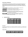
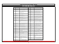
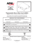
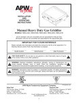
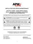
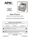
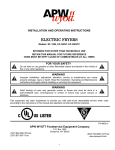
INSTALLATION
AND
OPERATING
INSTRUCTIONS
Models: Start with the prefix QST or ECO 4000:
350E, 350L, 500E, 500L
ECO-4000
INTENDED FOR OTHER THAN HOUSEHOLD USE
RETAIN THIS MANUAL FOR FUTURE REFERENCE
UNIT MUST BE KEPT CLEAR OF COMBUSTIBLES AT ALL TIMES
FOR YOUR SAFETY: Do not store or use gasoline or other flammable vapors and liquids
in the vicinity of this or any other appliance.
WARNING: Improper installation, adjustment, alteration, service or maintenance can
cause property damage, injury or death. Read the Installation, Operating and Maintenance
Instructions thoroughly before installing or servicing this equipment.
Improper installation, adjustment, alteration, service or maintenance can cause property damage, injury or
death. Read the Installation, Operating and Maintenance Instructions thoroughly before installing or servicing
this equipment.
This equipment has been engineered to provide you with year-round dependable service when used according
to the instructions in this manual and standard commercial kitchen practices.
P/N 8898800 2/11
Phone:
Fax:
Toll Free:
Website:
E-mail:
+1 (214) 421-7366
+1 (214) 565-0976
+1 (800) 527-2100
www.apwwyott.com
[email protected]
APWWYOTT
729 Third Avenue
Dallas, TX 75226
1
IMPORTANT FOR FUTURE REFERENCE
Please complete this information and retain this manual for the life of the equipment. For
Warranty Service and/or Parts, this information is required.
Model Number
Serial Number
Date Purchased
TABLE OF CONTENTS
SECTION
1
2
3
4
5
6
ITEM
Owner’s Information
Safety Information
Specifications
Installation Instructions
Operation
Programming
PAGE
2
2
3
4
5
7
SECTION
7
8
9
10
11
12
ITEM
Cleaning
Troubleshooting
Preventative Maintenance
Wiring Diagrams
Parts Lists & Exploded Views
Warranty
PAGE
8
9
9
10
12
17
WARNING: In Europe, appliance must be connected by an earthing cable to all other units
in the complete installation and thence to an independent earth connection in compliance
with EN 60335-1 and/or local codes.
WARNING: An earthing cable must connect the appliance to all other units in the
complete installation and from there to an independent earth connection.
1)
OWNER’S INFORMATION
General Information:
1. Always clean equipment thoroughly before first use. (See general cleaning instructions).
2. Check rating label for your model designation and electrical rating.
3. For best results, use stainless steel counter tops.
General Operation Instructions:
1. All food-service equipment should be operated by trained personnel.
2. Do not allow your customers to come in contact with any surface labeled "CAUTION HOT".
3. Never touch quartz or steel heaters.
Warranty Information:
Reliability Backed By APW Wyott’s Warranty:
All APW Wyott Toaster Ovens are backed by a one year parts and labor warranty, including On-Site
Service calls within 50 miles of authorized service technicians.
Service Information:
Service Hotline (800) 733-2203
2)
SAFETY INFORMATION
APW Wyott equipment is designed, built, and sold for commercial use and should be operated by trained
personnel only. Clearly post all CAUTIONS, WARNINGS and OPERATING INSTRUCTIONS near each unit to
insure proper operation and to reduce the chance of personal injury and/or equipment damage. This product is
used for the cooking, defrosting or re-thermalization of food products only.
Always disconnect power before servicing the unit. Surfaces will remain hot after power has been turned off.
Allow unit to cool before cleaning or servicing. Never clean the unit by immersing it in water. The unit is not
protected against water jets; DO NOT CLEAN THE TOASTER OVEN WITH A WATER JET. Always clean
equipment properly before first use.
2
Safety Signs and Messages
The following Safety signs and messages are placed in this manual to provide instructions and
identify specific areas where potential hazards exist and special precautions should be taken.
Know and understand the meaning of these instructions, signs, and messages. Damage to the
equipment, death or serious injury to you or other persons may result if these messages are not
followed.
This message indicates an imminently hazardous situation which, if
not avoided, will result in death or serious injury.
This message indicates a potentially hazardous situation, which, if
not avoided, could result in death or serious injury.
This message indicates a potentially hazardous situation, which, if
not avoided, may result in minor or moderate injury. It may also be
used to alert against unsafe practices.
This message is used when special information, instructions or
identification are required relating to procedures, equipment, tools,
capacities and other special data.
3)
SPECIFICATIONS
ECO 4000 (OR QST)
MODEL
ECO 4000 (OR QST)-350E
ECO 4000 (OR QST)-350L
ECO 4000 (OR QST)-500E
ECO 4000 (OR QST)-500E
ECO 4000 (OR QST)-500L
ECO 4000 (OR QST)-500L
VOLTS
120
120
208
240
208
240
WATTS
1700
1700
2800
2800
2800
2800
PH
1
1
1
1
1
1
Power Cord:
Six (6) foot, 3 wire grounded cord. If the supply cord is damaged, the manufacturer, or an authorized service
agent, must replace it in order to avoid a hazard and warranty. Please contact the factory by calling the 800 #
located on the unit.
Shipping Weight:
ECO 4000 (OR
QST)-350E
ECO 4000 (OR
QST)-350L
ECO 4000 (OR
QST)-500E
ECO 4000 (OR
QST)-500L
54 Lbs (24.5 kg)
54 Lbs (24.5 kg)
54 Lbs (24.5 kg)
54 Lbs (24.5 kg)
3
4)
INSTALLATION INSTRUCTIONS
If the carton appears damaged, or damage is discovered once the carton is opened, stop
immediately and contact the freight company to file a damage claim.
CAUTION: The ECO TOASTER Oven is shipped assembled except for installation of the
crumb tray assembly. Please remove all supports and packaging materials before
operating the unit. Failure to remove all packaging materials may lead to a fire and / or
damage to the appliance.
1. Remove all external packaging that is protecting top portion of unit
2. Remove unit from shipping container while in the upright position. The unit can be lifted out of the carton
by grasping under the back side and the conveyor of the appliance. Please remove the plastic bag.
3. Remove all internal packaging to the unit, if present.
4. Visually inspect all external and internal portions of unit for damage. Important: Inspect the Quartz
elements located inside the oven tunnel after removal of packing material. To inspect the quartz
elements, use a small mirror held under and over each element to detect cracks.
Important: The
quartz elements are fragile and will break under stress. Do not twist, pull, push, or otherwise
subject the quartz elements to stress.
5. Wipe down the exterior of the unit using a damp cloth with warm water. Do not use abrasive pads or
cleaners as they will damage the stainless steel surface.
NOTE: DO NOT USE CLEANERS OF ANY KIND ON THE QUARTZ HEATERS.
Note: Ambient Conditions - Make sure that the operating location is in an area where the ambient
temperature is held constant (minimum 70°F). Please avoid areas such as near exhaust fans and air
conditioning ducts.
Warning! Operating environment
Ensure that operation location is at a reasonable distance from combustible walls and materials
otherwise combustion or discoloration could occur. Do not cover the rear inlets or the side inlets and
outlets. Restricting or covering the air inlets and outlets may cause the unit to overheat and WILL
void your warranty.
Caution! Operating environment
Place unit on a stable, level counter at a convenient height for use. Turn the adjustable feet so that
unit is level to counter top. The top of the unit is not intended for use a shelf. Materials placed there
are at risk for fire.
6. Before plugging unit into wall, make sure that the power switch located on the back of “E” models and on
the Front of the “L” model is in the off position.
7. Warning! Ensure no hands, tools or parts or other unintended items are located on the conveyor as
injury will result when unit is turned on.
8. Plug unit into grounded electrical outlet with correct voltage, and plug configuration.
Warning! Using any receptacle that is not designed to match the attached cord and plug MAY cause
personal injury and WILL void your warranty. Please attach the ECO-4000, to an individual branch
circuit.
4
5)
OPERATION
1. The controls that operate the belt conveyor speed and the heaters are located on the front of the unit.
2. The On/Off switch is used to turn the unit on or off. Once the unit is turned on the conveyor will automatically
run. Warning: Ensure no hands, tools or parts are located on the conveyor as injury will result when unit is
turned on.
3. Note: Before moving the On / Off switch to the "On" position, please read the following statements:
4. A. CAUTION! HOT SURFACES! The exterior metal surfaces of the unit will get hot enough to cause burns.
Avoid touching these surfaces to prevent injury.
B. WARNING! SEVERE BURN HAZARD QUARTZ HEATERS. The quartz heaters or metal heaters
located in the top of the unit operate at very high temperatures. DO NOT TOUCH HEATERS AFTER
UNIT IS TURNED ON.
5. This oven has 2 heating zones, 1 above the conveyor, and one beneath the conveyor.
Operation Instructions for 350E and 500E “Toast on Demand Mode”
1. Turn the power switch located in the back of the unit to the on position.
2. Press the “PWR” button located on the control panel on the front of the unit.
3. The display will display a “-“ then the word “HEAT.” When the unit has completed its heat up
cycle it will display “IdLE.”
4. After the display shows “IdLE” the unit is ready to use.
5. Press the desired product button and place corresponding product on the wire rack so that it
touches the conveyor and may be conveyed into the toasting cavity.
6. Pressing the “DARKER” button will produce a darker toasted product.
7. Pressing the “LIGHTER” button will produce a lighter toasted product.
a. NOTE: the “DARKER” or “LIGHTER” button must be pressed immediately after product
button has been selected.
8. If the product is still not toasted enough or too much you can change the product key’s
parameters. “See Product Key Programming”.
9. Pressing the product key (“TOAST”, “MUFFIN”,”BAGEL”) multiple times will increase the on
time.
10. Pressing the “E-SAVE” button will cancel any product button command and return to the energy
saver or “IdLE” mode.
11. If “E-SAVE” is not pressed the toaster will automatically go to the “IdLE” mode after the
completion of product cycle.
12. To shut the unit off press and hold the “PWR” button for 10 seconds the display will display
“CooL.” Wait until the display is blank, then shut off the unit with the power button located on the
back panel. Do not shut off until the display is blank or improper cooling will result, and may
affect the life of the product.
Operation Instructions for 350E and 500E “Continuous or Full-On Mode”
1. Turn the power switch located in the back of the unit to the on position, (if unit is in the “OFF”
position). If Unit is already “ON” skip to step 5.
2. Press the “PWR” button located on the control panel on the front of the unit.
5
3. The display will display a “-“then the word “HEAT” when the unit has completed its heat up
cycle it will display “IdLE.”
4. After the display shows “IdLE” the unit is ready to use.
5. Press the “OTHER” Button located at the right side of the control panel.
6. The display will display “heat” (In early versions the display will show “pset” during this heat up
cycle)
7. The unit will heat up to the user defined preset temperature “factory default is 500 F”. To set
preset temperature see “Product Key Programming”.
8. The display will display “redy” and then show the countdown of time remaining in this
continuously on mode.
9. When timer countdown has begun, product can be placed at any time on the wire rack to be
conveyed into the toasting cavity.
10. Pressing the “LIGHTER” button will speed the conveyor up to achieve a lighter toasted product.
11. Pressing the “DARKER” button will slow the conveyor down to achieve a darker toasted
product.
12. Pressing the ”E-SAVE” at any time during the continuous on mode will cancel any product
button command and return to the energy saver or “IdLE” mode.
13. If “E-SAVE” is not pressed the toaster will automatically go to the “IdLE” mode after the
completion of program time cycle. (To change the time cycle see “Product Key Programming)
(Factory Default is 2:00 hours).
14. To shut the unit off press and hold the “PWR” button for 10 seconds the display will display
“CooL.” Wait until the display is blank, then shut off the unit with the power button located on the
back panel. Do not shut off until the display is blank or improper cooling will result, and may
affect the life of the product.
Operation Instructions for 350L and 500L
1. Turn the Power Switch on located on the front of the unit. When the unit is “ON”, the conveyor
belt will move.
2. Turn the timer to the desired time frame. There are 3 settings for using the timer
a. “OFF” – This removes the timer from the circuit and allows the conveyor and heating
elements to run as set in full-on mode.
b. “e-SAVE” – The green indicator light is on when this mode is active. The heating elements
are running at quarter power to keep the toaster prepared for shorter startup times, but
saving energy compared to a full-on run.
c. “TIMER” mode – The Amber indicator light is on when this mode is active. The timer allows
the toaster to run full-on until timed out, when it then switches to the e-SAVE mode.
3. Use the “TOP HEAT” and “BOTTOM HEAT” knobs to adjust to the desired temperature and
achieve the toasting pattern. Knobs can be turned to an “OFF” position, turning off the heat in a
full run mode. In “E-SAVE” mode, the elements (even if “OFF”) will cycle to keep cavity
temperature up.
4. Use the conveyor speed control to get the desired toast quality – “DARK” will run the conveyor
slower and “LIGHT” will run the conveyor faster.
6
6)
PROGRAMMING INSTRUCTIONS (ELECTRONIC – “E” MODELS)
Product Key Programming
Toast Button
1.
2.
3.
4.
5.
Press and hold the “LIGHTER” and “DARKER” buttons simultaneously for 20 seconds.
The display will display “PROG”.
Press the “TOAST” Button.
The Display will display “sped” then the current speed setting numeric value.
Pressing the “DARKER” button will increase the numeric value, increasing the conveyor speed.
Pressing the “LIGHTER” button will decrease the numeric value, which will decrease the conveyor
speed.
6. Pressing the toast button again will advance to the next parameter - Top element power level. The
display will display “top” then a numeric value between 0 thru 5. Setting the value 0 will turn the
element “OFF”. A 1 would be the lowest heat setting and a 5 would be the highest heat setting. The
factory default is 3.
7. Pressing the “TOAST” button again will advance you to the next parameter bottom element power
level. The display will display “bot” and a numeric value 0 thru 5. Setting the value 0 will turn the
element “OFF”. A 1 would be the lowest heat setting and a 5 would be the highest heat setting. The
factory default is 3.
8. Press the “TOAST” button again will save the settings and return to the “IdLE” or energy saver
mode.
Bagel Button
1.
2.
3.
4.
5.
Press and hold the “LIGHTER” and “DARKER” buttons simultaneously for 20 seconds.
The display will display “PROG”.
Press the “BAGEL” Button.
The display will display “sped” then the current speed setting numeric value.
Pressing the “DARKER” button will increase the numeric value, increasing the conveyor speed.
Pressing the “LIGHTER” button will decrease the numeric value, which will decrease the conveyor
speed.
6. Pressing the “BAGEL” button again will advance to the next parameter Top element power level.
The display will display “top” then a numeric value between 0 thru 5. Setting the value 0 will turn the
element “OFF”. A 1 would be the lowest heat setting and a 5 would be the highest heat setting. The
factory default is 3.
7. Pressing the “BAGEL” button again will advance you to the next parameter bottom element power
level. The display will display “bot” and a numeric value 0 thru 5. Setting the value 0 will turn the
element “OFF”. A 1 would be the lowest heat setting and a 5 would be the highest heat setting. The
factory default is 0.
8. Press the “BAGEL” button again will save the settings and return to the “IdLE” or energy saver
mode.
Muffin Button
1. Press and hold the “LIGHTER” and “DARKER” buttons simultaneously for 20 seconds.
2. The display will display “PROG”.
3. Press the “MUFFIN” Button.
7
4. The display will display “sped” then the current speed setting numeric value.
5. Pressing the “DARKER” button will increase the numeric value, increasing the conveyor speed.
Pressing the “LIGHTER” button will decrease the numeric value, which will decrease the conveyor
speed.
6. Pressing the “MUFFIN” button again will advance to the next parameter Top element power level.
The display will display “top” then a numeric value between 0 thru 5. Setting the value 0 will turn the
element “OFF”. A 1 would be the lowest heat setting and a 5 would be the highest heat setting. The
factory default is 4.
7. Pressing the “MUFFIN” button again will advance you to the next parameter bottom element power
level. The display will display “bot” and a numeric value 0 thru 5. Setting the value 0 will turn the
element “OFF”. A 1 would be the lowest heat setting and a 5 would be the highest heat setting. The
factory default is 1.
8. Press the “MUFFIN” button again will save the settings and return to the “IdLE” or energy saver
mode.
Other Button (Continuous on) (In Early Models this button is labeled “PROGRAM”)
1.
2.
3.
4.
Press and hold the “LIGHTER” and “DARKER” buttons simultaneously for 20 seconds.
The display will display “PROG”.
Press the “OTHER” Button.
The display will display “pset”, and then the preset temperature. Use the “LIGHTER” button to
decrease the temperature and the “DARKER” button to increase the temperature.
5. Press the “OTHER” button again to advance to the next parameter.
6. The display will display “tinc” then the time the unit will operate in this mode before returning to the
“IdLE” or energy saver mode. The time is displayed in hours and minutes. EXAMPLE: 2:35 is 2
hours 35 minutes. (Note the unit can be taken out of the continuous toast mode at any time by
pressing the “E-SAVE” button when in operation)
7. Use the “LIGHTER” button to decrease the time and the “DARKER” button to increase the time.
8. Press the “OTHER” button again to advance to the next parameter.
9. The display will display “top” and then the duty cycle for the top element. Use the “LIGHTER” button
to decrease the duty cycle or lower the heat and the “DARKER” button to increase the duty cycle or
increase the heat.
10. Press the “OTHER” button to advance to the next parameter.
11. The display will display “bot” and then the duty cycle for the bottom element. Use the “LIGHTER”
button to decrease the duty cycle or lower the heat and the “DARKER” button to increase the duty
cycle or increase the heat.
12. Press the “OTHER” button again to save and return to the “IdLE” mode or energy saver mode
7)
CLEANING
Insure the appliance has been turned off and has had sufficient time for all surfaces to cool down before
cleaning. Use only mild soap and water to clean this appliance. Appliance cleaning should be performed daily.
NOTE: DO NOT USE ABRASIVE CLEANING SOLUTIONS ON THIS APPLIANCE.
Daily Cleaning
• NEVER DIRECTLY SPRAY THE TOASTER WITH CLEANING CHEMICALS, SOLUTIONS, OR WATER.
ALWAYS APPLY CLEANING SOLUTIONS TO A CLEANING TOWEL OR CLOTH.
• Remove the crumb pans and wipe out debris with a damp rag and mild soap solution.
• Using a damp rag with mild soap and water, wipe down the exterior surfaces of the appliance.
8
•
•
Using a damp rag with mild soap solution, wipe down all areas of the conveyor. DO NOT ATTEMPT TO
CLEAN THE QUARTZ OR METAL HEATERS.
When units are in the stacked configuration, it is still necessary to clean between the units. Using a damp
rag with mild soap and water, wipe down the tops and undersides of all units. Ensure there are no foreign
objects between the units that could catch fire.
Using a damp rag with mild soap and water, wipe the surfaces of the stacking
spacers on all four corners.
8)
TROUBLESHOOTING
Always ask and check the following:
Not getting power:
1.
2.
3.
4.
5.
Is the unit connected to a live power source of the proper voltage?
Check the rating label. Is the unit connected to the correct power source?
Check the circuit breaker.
Is power switch "ON" and LED displaying information?
If the above checks out, and you still have problems, call your local service agent.
Conveyor not working:
1.
2.
3.
4.
Please refer to "Not getting power" section.
Check belt for obstructions. Belt may be jammed.
Note: At slower settings the conveyor moves very slow and may appear stalled, which is not the case.
If the above checks out, and you still have problems, call your local service agent.
Food not cooking properly:
1. Please refer to "Not getting power" section.
2. Is the controller and speed control adjusted to the desired setting? (See Product Key Programming
section to check button parameters)
3. If the above checks out, and you still have problems, call your local service agent.
9)
•
•
•
•
•
•
•
PREVENTATIVE MAINTENANCE SCHEDULE
Please follow the cleaning section for the daily preventative maintenance schedule.
DO NOT USE ABRASIVES OR CLEANING SOLUTIONS ON THIS APPLIANCE.
Routinely check before every operation that adequate distance is allowed between fans and anything that
would possibly allow foreign debris or substances to be taken in by inlet fan.
Clean fan guards on a daily basis to ensure proper inlet cooling to electrical components and efficient hot air
exhaust.
On a daily basis make sure side walls of tunnel oven remain clean to assist in maintaining even cooking
around product. Be careful not to bump or hit the quartz or metal heaters when wiping down.
Ensure belt is properly tensioned as to prevent slippage or binding, which causes strain on motor.
DO NOT ATTEMPT TO MAINTENANCE, SERVICE, OR CLEAN THE QUARTZ OR METAL HEATERS.
9
10
10)
WIRING DIAGRAM – ECO-4000 350E & 500E
WIRING DIAGRAMS/SCHEMATICS
11
WIRING DIAGRAM –ECO 4000 350L & 500L
11)
PARTS LISTS & EXPLODED VIEWS
EXPLODED VIEW 500E
18
2
19
8
36
1
20
2
70
1
21
2
22
2
80
1
24
2
23
1
26
2
25
2
68
1
37
1
85
2
83
2
62
2
63
4
29
2
60
1
27
2
39
1
28
1
67
2
29
2
30
1
38
1
41
1
53
1
42
1
31
1
59
1
40
1
64
1
32
1
34
1
33
1
26
2
25
2
24
2
43
1
44
1
55
1
8
4
45
1
47
1
52
1
54
1
79
1
50
1
35
1
12
58
1
61
2
46
2
PARTS LISTS & EXPLODED VIEWS
ECO 4000 500E Parts Lists
Item
Part #
Title
Item
Part #
Title
Item
Part #
Title
8
86621-00
LEG 1" CHROME
38
15346-00
CORD, 14/3 HSJO NEMA 6-20P 72"
64
48395600 DRIVE SHAFT ASSY SEGMENTED BELT
18
21851450
COVER, ELEMENT CART. LS QST
39
21851437
PANEL, SIDE RIGHT QST
67
89784-00 BUSHING, 7/8 SNAP, HEYCO
19
30061030 ELEMENT, QUARTZ 52 VOLTS 350W
40
89792-00 STRAIN RELIEF
68
21851446
TRAY, ELEMENT BOTTOM (E) QST
20
21851447
BRACKET, ELEMENT CART. MOUNTING (E) QST
41
48514300 MOTOR, GEAR 230V 60HZ 9RPM
70
21851462
TRAY, ELEMENT TOP (E) QST
21
21851449
RETAINER, ELEMENT END QST
42
31007-33
79
21851410
DECAL, QST ELECTRONIC
22
21851477
BRACKET, MOUNTING RTD QST
43
48326100 SPROCKET, 12 TOOTH 1/4 PITCH 3/8 BORE
80
1376000
HIGH LIMIT CLOSED AT 300°F
23
21851442
RETAINER, SHAFT
44
48290100 CHAIN DRIVE 1/4 PITCH X 68
83
43813103
LABEL, WRNG, HOT SURFC
24
21851443
BRACKET, BEARING QST
45
48326000 SPROCKET, 18 TOOTH 1/4 PITCH 5/16 BORE
85
43813149
LABEL, WRN HOT SURF (FRNCH)
25
48324800 BEARING, SHAFT
46
43812500 BEARING FLANGED POLYMER
26
48386800 SPACER, CONVEYOR SHAFT
47
21851463
DUCT, AIR QST
27
89456-00 CLAMP-LOOP 3/16IN
50
21851439
TRAY CRUMB
28
1475051
PROBE,2 RTD 1000 OHMS WITH CONNECTOR
52
21851454
PANEL, CONTROL QST VE
29
784682
FAN, AXIAL 230V
53
21851458
SIDE, CONVEYOR LS QST
30
21851473
DUCT, FAN QST
54
48292000 BELT, WIRE 27x.05 3 SEG.
31
1377000
HIGH LIMIT RESETTABLE OPEN @180
55
21851457
32
1451700
TRANSFORMER, CLASS 2 120/240V
58
43812200 SHAFT & IDLER WHEEL W/ASSY
33
21851459
BASE, COMPONENT MOUNTING QST
59
11072-00
BLOCK TERINAL, 6 STATION 600V
34
1400115
CONTROL, TOASTER PCB
60
21851451
COVER, ACCESS BACK QST
35
21851460
DRAWER, HOLDING QST
61
21851441
CLIP BEARING QST
36
21851438
PANEL, SIDE LEFT QST
62
21851452
COVER, ELEMENT CART RS QST
37
1305612
SWITCH, ROCKER 20 AMP
63
21851468
INSULATION, QST TOASTER (E)
FUARD, FAN FINGER
SIDE, CONVEYOR RS QST
13
PARTS LISTS & EXPLODED VIEWS
ECO 4000 500L
18
1
30
1
19
1
62
1
20
1
22
2
21
1
24
2
23
2
56
1
25
2
54
1
60
1
33
1
25
2
32
1
31
1
87
1
86
1
53
1
27
1
76
1
80
1
35
1
47
1
36
1
77
1
46
1
88
1
83
1
81
1
28
1
84
1
79
1
34
1
57
1
24
2
23
2
22
2
37
1
38
1
49
1
39
1
8
1
48
1
85
1
44
1
29
1
14
52
1
55
1
40
1
PARTS LISTS & EXPLODED VIEWS
ECO 4000 500L Parts List
Item
Part Number
Title
Item
Part Number
Title
8
86621-00
LEG 1" CHROME
44 21851439
TRAY CRUMB
18
21851482
ELEMENT, 208V 1400W
46 21851464
PANEL, CONTROL QST VL
19
21851453
BRACKET, ELEMENT CART.
47 21851458
SIDE, CONVEYOR LS QST
MOUNTING (L) QST
48 48292000
BELT, WIRE 27x.05 3 SEG.
20 21851477
BRACKET, MOUNTING RTD QST
49
SIDE, CONVEYOR RS QST
21
RETAINER, SHAFT
52 43812200
SHAFT & IDLER WHEEL W/ASSY
22 21851443
BRACKET, BEARING QST
53 11072-00
BLOCK TERINAL, 6 STATION 600V
23 48324800
BEARING, SHAFT
54 21851451
COVER, ACCESS BACK QST
24 48386800
SPACER, CONVEYOR SHAFT
55 21851441
CLIP BEARING QST
25 784682
FAN, AXIAL 230V
56 21851468
INSULATION, QST TOASTER (E)
HIGH LIMIT RESETTABLE OPEN
57 48395600
DRIVE SHAFT ASSY SEGMENTED
21851442
27 1377000
21851457
@180
BELT
28 21851459
BASE, COMPONENT MOUNTING QST
60 21851456
TRAY, ELEMENT BOTTOM (L) QST
29 21851460
DRAWER, HOLDING QST
62 21851465
TRAY, ELEMENT TOP (L) QST
30 21851438
PANEL, SIDE LEFT QST
76 21851485
LIGHT, INDICATOR GREEN
31
SWITCH, ROCKER 20 AMP
77
21851484
DECAL QST (L)
32 15346-00
CORD, 14/3 HSJO NEMA 6-20P 72"
79
21851487
INSULATION, TOP CTRL BOX QST
33 21851437
PANEL, SIDE RIGHT QST
80 21851486
LIGHT, INDICATOR AMBER
34 89792-00
STRAIN RELIEF
81
RHEOSTAT, 208/240V w/TERMINALS
35 48514300
MOTOR, GEAR 230V 60HZ 9RPM
83 1301602
INFINITE SWITCH 240V
36 31007-33
FUARD, FAN FINGER
84 21851488
INSULATION, TOP CTRL BOX QST
SPROCKET, 12 TOOTH 1/4 PITCH 3/8
85 781189
ZYTRON KNOB
1305612
37 48326100
BORE
38 48290100
CHAIN DRIVE 1/4 PITCH X 68
39 48326000
SPROCKET, 18 TOOTH 1/4 PITCH
5/16 BORE
40 43812500
48322250
86 1400175
TIMER MECHANICAL 60 MIN 230V
NO BZR
87
1313300
88 1475020
BEARING FLANGED POLYMER
15
RELAY,FULL 3PDT 10A@240V
RELAY, ELECTRONIC 40A 240V
NOTES:
16
12. APW WYOTT EQUIPMENT LIMITED WARRANTY
APW Wyott Food service Equipment Company warrants it's equipment against defects in materials and workmanship, subject to the
following conditions:
This warranty applies to the original owner only and is not assignable.
Should any product fail to function in its intended manner under normal use within the limits defined in this warranty, at the option of
APW Wyott such product will be repaired or replaced by APW Wyott or its Authorized Service Agency. APW Wyott will only be
responsible for charges incurred or service performed by its Authorized Service Agencies. The use of other than APW Wyott Authorized
Service Agencies will void this warranty and APW Wyott will not be responsible for such work or any charges associated with same. The
closest APW Wyott Authorized Service Agent must be used.
This warranty covers products shipped into the 48 contiguous United States, Hawaii, metropolitan areas of Alaska and Canada. There will
be no labor coverage for equipment located on any island not connected by roadway to the mainland.
Warranty coverage on products used outside the 48 contiguous United States, Hawaii, and metropolitan areas of Alaska and Canada may
vary. Contact the international APW Wyott distributor, dealer, or service agency for details.
Time Period
One year for parts and one year for labor, effective from the date of purchase by the original owner. The Authorized Service Agency may,
at their option, require proof of purchase. Parts replaced under this warranty are warranted for the un-expired portion of the original
product warranty only.
Exceptions
* Gas/Electric Cookline: Models HCB, HCRB, HMG, HTG, HHP, HHPS, GCB, GCRB, GF, GGM, GGT, CHP-H, EF, EG,
EHP. Three (3) Year Warranty on all component parts, except switches and thermostats. (2 additional years on parts only.
No labor on second or third year.)
* Broiler Briquettes, Rock Grates, Cooking Grates, Burner Shields, Fireboxes: 90 Day Material Only. No Labor.
* Heat Strips: Models FD, FDL, FDD, FDDL. Two (2)Year Warranty on element only. No labor second year.
* Glass Windows, Doors, Seals, Rubber Seals, Light Bulbs: 90 Day Material Only. No Labor.
In all cases, parts covered by extended warranty will be shipped FOB the factory after the first year.
Portable Carry In Products
Equipment weighing over 70 pounds or permanently installed will be serviced on-site as per the terms of this warranty. Equipment
weighing 70 pounds or under, and which is not permanently installed, i.e. with cord and plug, is considered portable and is subject to the
following warranty handling limitations. If portable equipment fails to operate in its intended manner on the first day of connection, or
use, at APW Wyott's option or its Authorized Service Agency, it will be serviced on site or replaced.
From day two through the conclusion of this warranty period, portable units must be taken to or sent prepaid to the APW Wyott
Authorized Service Agency for in-warranty repairs. No mileage or travel charges are allowed on portable units after the first day of use. If
the customer wants on-site service, they may receive same by paying the travel and mileage charges. Exceptions to this rule: (1)
countertop warmers and cookers, which are covered under the Enhanced Warranty Program, and (2) toasters or rollergrills which have in
store service.
Exclusions
The following conditions are not covered by warranty:
* Equipment failure relating to improper installation, improper utility connection or supply and problems due to ventilation.
* Equipment that has not been properly maintained, calibration of controls, adjustments, damage from improper cleaning and
water damage to controls.
* Equipment that has not been used in an appropriate manner, or has been subject to misuse or misapplication, neglect, abuse,
accident, alteration, negligence, damage during transit, delivery or installation, fire, flood, riot or act of god.
* Equipment that has the model number or serial number removed or altered.
If the equipment has been changed, altered, modified or repaired by other than an Authorized Service Agency during or after the warranty
period, then the manufacturer shall not be liable for any damages to any person or to any property, which may result from the use of the
equipment thereafter.
This warranty does not cover services performed at overtime or premium labor rates. Should service be required at times which normally
involve overtime or premium labor rates, the owner shall be charged for the difference between normal service rates and such premium
rates. APW Wyott does not assume any liability for extended delays in replacing or repairing any items beyond its control.
In all cases, the use of other than APW Wyott Authorized OEM Replacement Parts will void this warranty.
This equipment is intended for commercial use only. Warranty is void if equipment is installed in other than commercial application.
Water Quality Requirements
Water supply intended for a unit that has in excess of 3.0 grains of hardness per gallon (GPG) must be treated or softened before being
used. Water containing over 3.0 GPG will decrease the efficiency and reduce the operation life of the unit.
Note: Product failure caused by liming or sediment buildup is not covered under warranty.
"THE FOREGOING WARRANTY IS IN LIEU OF ANY AND ALL OTHER WARRANTIES EXPRESSED OR IMPLIED
INCLUDING ANY IMPLIED WARRANTY OF MERCHANTABILITY OR FITNESS FOR PARTICULAR PURPOSES AND
CONSTITUTES THE ENTIRE LIABILITY OF APW WYOTT. IN NO EVENT DOES THE LIMITED WARRANTY EXTEND
BEYOND THE TERMS STATED HEREIN."
9/05
17